
Abstract
The difference in cutter arrangement between the atmospheric cutterhead and the pressurized cutterhead leads to a significant difference in the cutting performance of the two cutterheads. Due to the lack of quantitative comparison and analysis of the cutting performance, the selection of cutterheads lacks a quantitative and scientific basis. In this paper, an atmospheric cutterhead and a pressurized cutterhead with 15.07 m diameters are taken as the research objects, which were excavated in the same slightly weathered argillaceous siltstone strata for a certain tunnel project in Guangzhou. Rotary cutting rock simulations of cutter groups in the central area, front area and edge area of the two cutterheads are established, where the rock damage form, load characteristics and specific energy of the three areas of the two cutterheads are comparatively analyzed. Furthermore, the actual engineering tunneling performance of the two cutterheads was analyzed to verify the simulation results. The vertical force and rolling force of each disc cutter on the pressurized cutterhead are 75.7% and 78.2% of those on the atmospheric cutterhead, respectively, where the cutter spacing of the pressurized cutterhead is smaller. The rock-breaking specific energy of the cutter group in each area of the pressurized cutterhead is 95.6–73.4% of that of the atmospheric cutterhead. Meanwhile, the total thrust and torque of the pressurized cutterhead are 111.4% and 115.2% of those of the atmospheric cutterhead, respectively, where the pressurized cutterhead is equipped with more cutters. Therefore, the overall cutting performance of the pressurized cutterhead is better than that of the atmospheric cutterhead in slightly weathered argillaceous siltstone strata. This study provides a quantitative comparison method for the atmospheric cutterhead and the pressurized cutterhead under the same geological conditions, which can be extended to the structure selection of large-diameter cutterheads of shield machines under other geological conditions.
Keywords
Introduction
Super-large-diameter shields (diameter > 14 m) have been widely applied in the construction of subsea tunnels, river-crossing tunnels, oil and gas pipelines, and urban three-dimensional transportation hubs, owing to their advantages of fast tunneling speed, enhanced safety, cost-effectiveness, and high space utilization efficiency.1–4 Hundreds of cutting tools (cutters, inserted tooth cutters, or ripper tools) arranged on the cutterhead face collectively interact with the tunnel face to achieve large-section tunnel excavation, where their cutting performance directly determines equipment efficiency and construction productivity. According to the different methods of tool replacement, the optional cutterhead types include atmospheric cutterheads and pressurized cutterheads. An atmospheric cutterhead allows technicians to enter the cutterhead and replace cutters at normal atmospheric pressure, without being exposed to the high pressure from the soil and water at the excavation face. However, in the process of replacing the cutters on a pressurized cutterhead, the pressure of the slurry supporting the excavation face needs to be maintained by high-pressure gas. Technicians must work in a pressurized environment (above atmospheric pressure) to balance the external pressure. The different tool change methods lead to significant differences in the structure and tool arrangement of the two cutterheads. Pressurized cutterheads typically adopt spoke or spoke-plate structures with densely and uniformly arranged tools along the spokes to ensure full-face continuous cutting, whereas atmospheric cutterheads employ panel structures where the tool layout is spatially constrained by replaceable tool cartridge dimensions and chamber structures, resulting in a sparse block-wise distribution. 5 The difference in cutter arrangement leads to variations in cutting performance and mechanical behavior of the two cutterheads. However, there has been no systematic quantitative analysis of the differences in tunneling efficiency and service performance of the two cutterheads under the same stratum, which leads to a lack of scientific methods and theoretical basis for the selection of cutterheads. Therefore, it is urgent to compare the cutting performance of the atmospheric and pressurized cutterheads and provide a theoretical basis for the selection of the two cutterheads in the cross-sea and cross-river tunnel projects under high water pressure environments.
At present, the research on the rock-breaking mechanism and cutter load characteristics mainly includes the following: in studies on the rock-breaking mechanism, Jiang et al. 6 used PFC2D to study crack propagation, stress distribution and rock slag formation mechanisms during the cutter rock-breaking process. Liu et al. 7 used the two-dimensional discrete element method to explore the influence of prefabricated cracks with different dip angles on the rock-breaking process and crack propagation mode under the action of the cutter. Based on linear elastic fracture mechanics (LEFM), Exadaktylos et al. 8 simulated the process of transverse cracks initiated beneath the cutter tip and propagating quasi-statically toward adjacent cutter grooves. In studies on rock-breaking load prediction models of cutters, Rostami 9 proposed the widely used Colorado School of Mines (CSM) model by combining experimental data with engineering experience. She et al. 10 proposed a rock-breaking mechanism and force prediction model for cutters considering the influence of a dense core. Geng et al. 11 established a prediction model of cutter rock breaking force based on four machine learning methods. In comprehensive studies of the rock-breaking performance of cutters, Lin et al., 12 Pan et al. 13 and Li et al. 14 studied the influence of the type of cutter, rock confining pressure and pre-groove depth on rock breaking load and rock breaking specific energy by carrying out linear cutting tests. Kang et al. 15 analyzed the influence of the width of the cutter on rock breaking load and rock breaking specific energy based on the discrete–continuous coupling numerical method. Fang et al. 16 used the RBD-DEM method to study the influence of penetration, line velocity and cutter wear on the rock breaking performance of cutters in soft strata. It can be seen from the above research that rock-breaking efficiency and cutter load are important indicators for the comprehensive evaluation of cutting performance.
The above analysis of the rock fragmentation mechanism and characteristics of cutting tools has laid a theoretical foundation for studying the overall structure of the cutterhead and its cutting performance. However, the cutting performance of the cutterhead is determined not only by the rock breaking capacity of the cutting tools but also by their layout, which is in turn constrained by the overall structure of the cutterhead. Regarding the structure of the cutterhead and the arrangement of cutting tools, Xia et al. 5 proposed an innovative collaborative strategy for the structure of the cutterhead and the layout of disc cutters to address the mutual constraints between the opening design of atmospheric cutterheads and cutter arrangement. Li et al. 17 discussed the selection of spoke-type and panel-type cutterheads and the configuration of cutting tools in coarse-grained soil geology. Farrokh et al. 18 examined the relationship between the design parameters of cutterhead openings and factors such as cutterhead diameter, geological type, and center opening type by analyzing field data from numerous soft-ground tunneling projects. In terms of the cutting performance of the cutterhead, Zhang et al. 19 investigated the effects of cutter shape, rock strength, and cutterhead rotation speed on cutterhead load and vibration characteristics using a coupled discrete element–multibody dynamics model for multi-cutter rock breaking. Zhang et al. 20 analyzed the force characteristics and fragmentation efficiency of cutters in different zones by establishing a three-dimensional rock fragmentation model of the full cutterhead. Sun et al. 21 studied the relationship between rock strength, integrity, and cutterhead cutting force, torque, and vibration response through a synchronous monitoring system of a full-scale rotary cutting machine. Wu et al. 22 established a three-dimensional dynamic tunneling simulation model of the cutterhead and evaluated the tunneling performance in terms of rock fragmentation volume, cutterhead tunneling load, and surrounding rock stress distribution. Han et al. 23 found through numerical simulations that the cutterhead load approximately follows a normal distribution, with its thrust and torque largely dependent on the penetration rate and rock strength. Li et al. 24 quantitatively evaluated the performance of three mainstream cutterhead designs (conical, conical–planar composite, and planar) using an integrated measurement framework combining 3D modeling and Adams dynamics simulation.
In summary, from the rock-breaking mechanism and rock-breaking characteristics of the disc cutter, to the cutting performance of the cutter group and the cutterhead, the relevant research has achieved relatively systematic results. Among them, the numerical simulation method is widely used in related research due to its low cost and high efficiency. However, current research predominantly focuses on single-cutters, double-cutters, and cutter groups, with limited comprehensive analysis of the cutting performance of entire cutterheads. Moreover, the cutterheads studied are generally of small diameters. For ultra-large-diameter cutterheads, the increase in diameter leads to a quadratic growth in the size of numerical models. The enormous computational load makes it highly challenging to directly establish a full cutterhead cutting model.
This study presents a quantitative analytical method for comparing the cutting performance of the atmospheric cutterhead and the pressurized cutterhead. An atmospheric cutterhead and a pressurized cutterhead excavated in slightly weathered argillaceous siltstone strata in the Haizhuwan Tunnel Project are taken as research objects. The characteristics and differences in cutter arrangement in the central, front, and edge areas of the two cutterheads are deeply analyzed, and the dynamic numerical models of rotary cutting for cutter groups in different regions are established. The differences in cutting performance between the atmospheric cutterhead and the pressurized cutterhead are revealed from the perspectives of the dynamic evolution process of rock damage, load characteristics of the cutter and rock-breaking efficiency of the cutter groups, and the reasons for the differences in cutting performance are analyzed from the aspects of cutter spacing, cutting sequence and installation radius. Finally, the actual tunneling data of the atmospheric cutterhead and the pressurized cutterhead are compared and analyzed to verify the correctness of the simulation results. The research results can provide a quantitative method for the selection of the shield cutterhead in various strata.
General situation of the project
The total length of the shield tunnel in the Haizhuwan project is 4195 m. The length of the west line of the shield section is 2093 m, and the length of the east line is 2102 m. The west line and the east line are excavated simultaneously using slurry balance shield machines with the atmospheric cutterhead and the pressurized cutterhead, respectively. The excavation diameter of the tunnel is 15.07 m. The shield machine advances from south to north and passes through the Sanzhixiang Waterway (205 m), Luoxi Island Building Group (880 m), Lijiao Waterway (425 m) and the waterway levee for a long distance. The shield tunnel passes through strata with high water pressure and strong permeability. The construction risk is high, and the construction environment is complex, as shown in Figure 1.
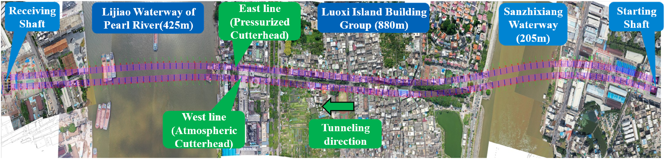
General situation of the Haizhuwan tunnel project.
Geological conditions of the project
The geological profile and geological distribution map of the Haizhuwan Tunnel are shown in Figure 2(a) and (b), respectively. The tunnel crossing area is dominated by moderately weathered and slightly weathered argillaceous siltstone, silty clay, silt, muddy clay, fine sand, and medium–coarse sand, with local gravelly sand. The length of the moderately and slightly weathered argillaceous siltstone is 1494 m (accounting for 75.1%). The average compressive strength of the rock is 20 MPa, and the maximum is 50 MPa. The slightly weathered argillaceous siltstone is the predominant geological formation in the tunnel crossing area, accounting for 62.8% of the total. In the 191–340 ring excavation section, the geology of the eastern line and western line tunnels is a single slightly weathered argillaceous siltstone. This uniform geological condition offers an ideal condition for comparing the cutting performance of the two cutterheads. Therefore, this study conducts a comparative analysis of cutterhead performance based on this specific stratum. The maximum buried depth is 48 m, and the maximum water pressure is 5.2 bar. The initial overburden soil is 9.1 m, and the receiving overburden soil is 10.2 m, both of which are less than 0.7 D (D is the tunnel diameter). The subsurface stratum between 0.1–3.3 m depth consists of a phreatic aquifer characterized by developed rock pores and fractures, containing pore-fissure confined water, with both groundwater and soil exhibiting mild corrosivity.
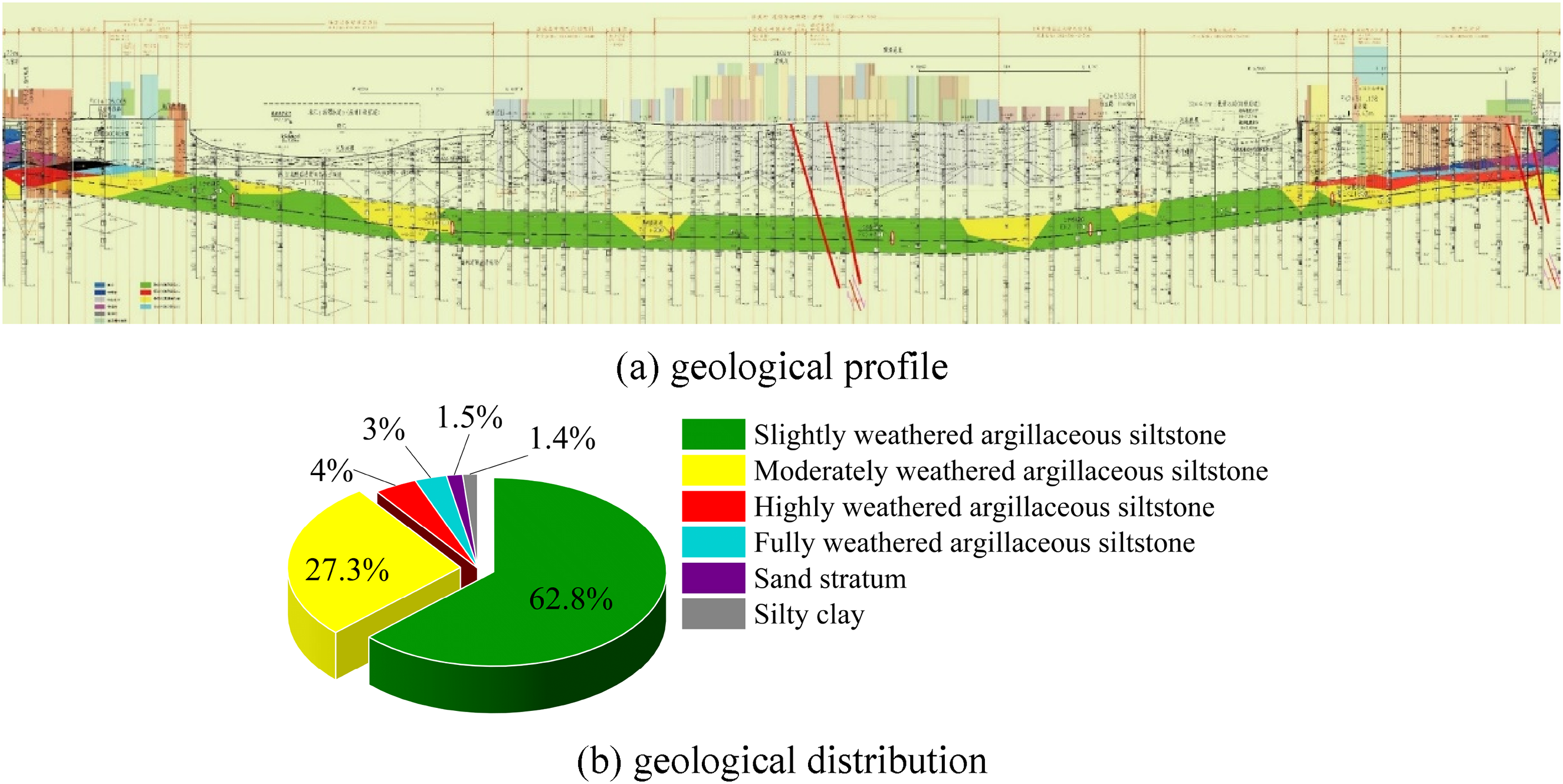
Haizhuwan tunnel engineering geology. (a) Geological profile and (b) geological distribution.
Structure of the two cutterheads
The structural diagrams and parameters of both the atmospheric cutterhead and the pressurized cutterhead are presented in Figure 3 and Table 1, respectively. The two cutterhead configurations exhibit significant differences in structural design: the atmospheric cutterhead adopts a panel-type structure with a smaller opening ratio, fewer cutters (76 in total), a sparser cutter arrangement and larger cutter spacing, while the pressurized cutterhead adopts a spoke-type structure with a larger opening ratio, more cutters (112 in total), a denser cutter arrangement and smaller cutter spacing.

Cutterhead structure of the Haizhuwan tunnel. (a) Atmospheric cutterhead and (b) pressurized cutterhead.
Parameters of the atmospheric cutterhead and pressurized cutterhead.

Note: All cutter quantities in the table refer to the number of cutting edges, each single-cutter counts as 1, while each double-cutter counts as 2. Single-cutter and double-cutter are abbreviated as “single” and “double,” respectively, in the table.
Establishment of the numerical model
In order to quantitatively analyze the differences between the cutting performance of the atmospheric cutterhead and pressurized cutterhead, it is necessary to establish a numerical model to simulate and analyze the dynamic cutting process of the two cutterheads. The establishment process of the numerical model includes geometric model establishment, material setting, application of loads and boundary conditions, as shown in Figure 4. In order to simulate the dynamic process of rock cutting involving large deformation, high strain rate and complex material failure, the explicit dynamic finite element analysis (FEA) method is adopted. The software used for the simulation is LS-DYNA. As the industry’s leading explicit dynamic analysis software, it has powerful capabilities and high reliability in dealing with shocks, collisions, and complex material failure processes such as rock cutting. 25

Flow chart of the numerical model establishment.
Geometric model
The subject of this study is a cutterhead with a diameter of 15.07 m. If a full-cutterhead cutting numerical simulation is to be conducted, the diameter of the rock in the numerical model must be larger than 15.07 m. At the same time, to simulate the rock fragmentation process by the cutter group in a way that is closer to real working conditions, the mesh of the rock should be as fine as possible. This will ultimately result in a huge number of mesh elements, making a single simulation excessively time-consuming. Therefore, under the existing computational conditions, it is difficult to carry out numerical simulations of rock cutting by all the disc cutters on the cutterhead. Since the cutter layout and installation radius are key factors affecting the rock breaking performance of the cutter group, this paper establishes zonal models for the disc cutters on the cutterhead to consider the influence of differences in cutter layout across the center, front, and edge areas on the rock fragmentation process. Furthermore, for a wide range of front-area disc cutter groups, rock fragmentation models under different installation radii were established to consider the impact of installation radius on the rock-breaking performance of the disc cutter group.
The geometric model of rock cutting by central area cutter groups is presented in Figure 5. The central area of the atmospheric cutterhead consists of 12 cutters (numbered CX1 to CX12), the cutter spacing is 135 mm, the radius of the rock model is 1630 mm and the thickness is 50 mm, as shown in Figure 5(a). The central area of the pressurized cutterhead also comprises 12 cutters (numbered DX1 to DX12); the cutter spacing is 101.5 mm, the radius of the rock model is 1250 mm and the thickness is 50 mm, as shown in Figure 5(b).

Geometric model of rock cutting by central area cutter groups. (a) Atmospheric cutterhead and (b) pressurized cutterhead.
The geometric model of rock cutting by front area cutter groups is presented in Figure 6. Due to the excessive number of front cutters, with the atmospheric cutterhead reaching 52 cutters and the pressurized cutterhead reaching 78 cutters, the coverage range is too extensive. If a model of rock cutting by all front cutters were established, it would make the model too large and difficult to compute. Therefore, only a portion of the cutters was selected to build the model.
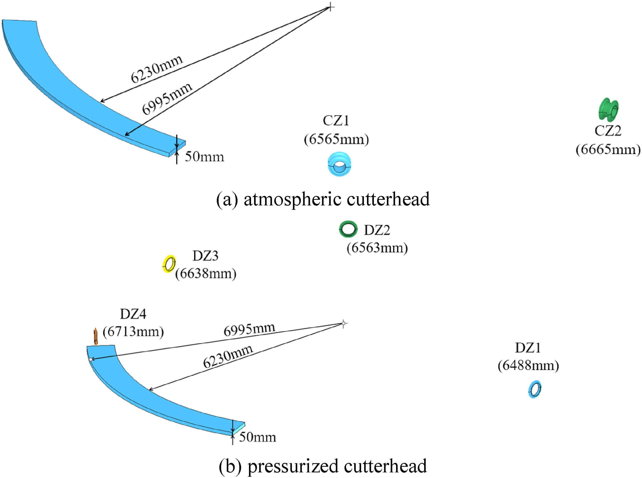
Geometric model of rock cutting by front area cutter groups. (a) Atmospheric cutterhead and (b) pressurized cutterhead.
The specific modeling process is as follows: first, select two double-cutters installed within the radius range of 6230–6995 mm from the front area of the atmospheric cutterhead, and select four single-cutters installed within the radius range of 6230–6995 mm from the front area of the pressurized cutterhead to establish the geometric model shown in Figure 2. According to the order of increasing installation radius, the cutters in the geometric models of the front areas of the atmospheric cutterhead and the pressurized cutterhead are sequentially numbered as CZ1–CZ2 and DZ1–DZ4, respectively. The numbering and installation radii are shown in Figure 6(a) and (b), respectively. To reduce the amount of calculation, the rock model is constructed as only a 1/6 annulus. At the same time, the geometric models of the front area in the ranges of 5230–5995 mm, 4230–4995 mm, and 3230–3995 mm were also established to reveal the differences in cutting characteristics between the atmospheric cutterhead and the pressurized cutterhead in the whole front area.
The geometric model of rock cutting by edge-area cutter groups is presented in Figure 7. The geometric model of the edge area of the atmospheric cutterhead includes four double-cutters and four single cutters. The spacing of the double cutters is 100 mm, and the installation angle is 13–48°. The spacing of the single cutters is 85 mm, and the installation angle is 61–67°. According to the order of increasing installation radius, the cutters in the edge area of the atmospheric cutterhead are numbered as CB1–CB8, as shown in Figure 7(a). The geometric model of the edge area of the pressurized cutterhead includes 22 single cutters; the cutter spacing is 43.6–61 mm, and the installation angle is 11–70°. According to the order of increasing installation radius, the cutters in the edge area of the pressurized cutterhead are numbered as DB1–DB22, as shown in Figure 7(b). In order to reduce the amount of calculation, the rock model is constructed as only a 1/6 annulus.
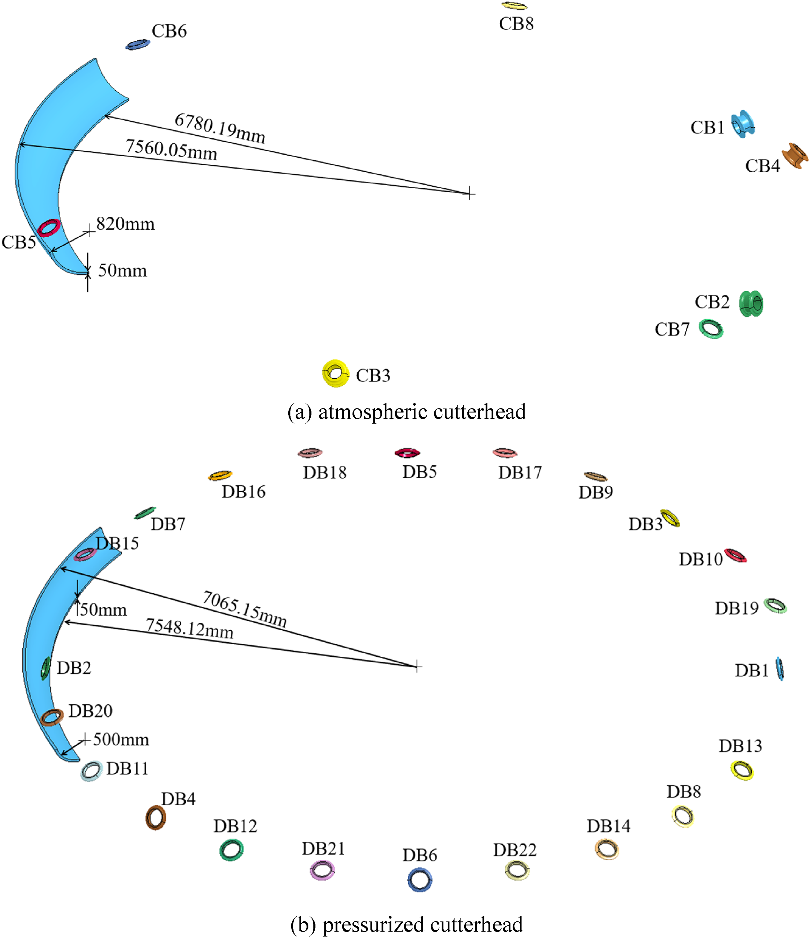
Geometric model of rock cutting by edge area cutter groups. (a) Atmospheric cutterhead and (b) pressurized cutterhead.
Materials
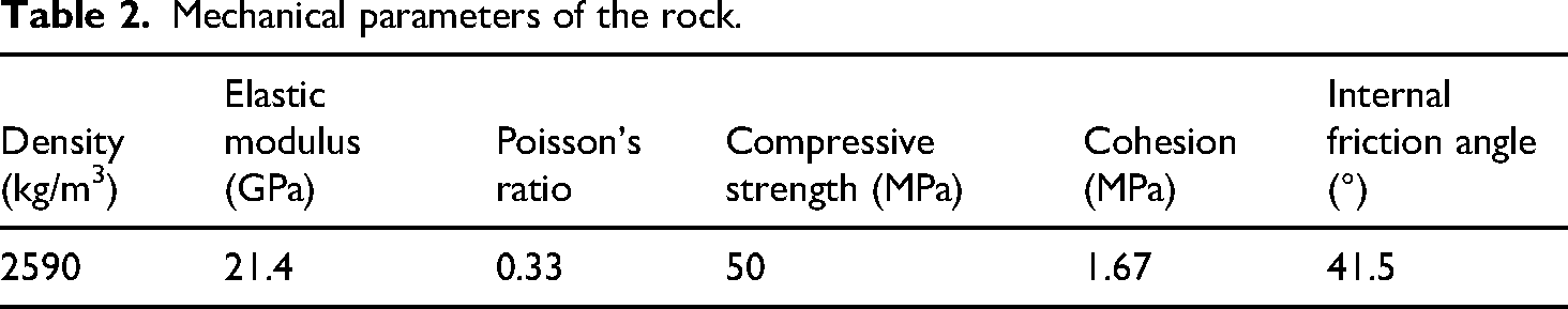
In this paper, the cutter loads and internal stress distribution characteristics of rock in the cutting process are the focus, rather than the deformation of the cutter. The stiffness of the disc cutter is significantly higher than that of the rock, where the deformation of the cutter is much smaller than that of the rock. Furthermore, the deformation and wear of the cutter are very small during the short simulation process. Therefore, the cutters are defined as rigid bodies with a density of 7850 kg/m³, an elastic modulus of 210 GPa, and Poisson's ratio of 0.3. The slightly weathered argillaceous siltstone rock sample is shown in Figure 8. The mechanical parameters of the rock are shown in Table 2. These data were obtained from the geotechnical engineering investigation conducted by the project department before construction. The rock material is selected as the HJC (Holmquist-Johnson-Cook) constitutive model. The constitutive model comprehensively considers the strain rate effects, damage evolution effects, confining pressure effects and crushing and compaction effects. It can better describe the mechanical behavior of concrete and rock materials under large deformation, high strain rate and high hydrostatic pressure, 26 which is widely used in the studies of the interaction between cutter and rock.22,27,28

Slightly weathered argillaceous siltstone.
Mechanical parameters of the rock.
Load and boundaries
The unified velocity load and boundary conditions are applied to the cutter group cutting models of the center, front and edge areas of the atmospheric cutterhead and the pressurized cutterhead. The motion parameters of the cutter group refer to the actual tunneling parameters in the project. The rotation speed of the cutter group is 1.2 r/min, the penetration is 12 mm/r, and the propulsion speed is 14.4 mm/min. Since the cutter group is set to rotate and intrude into the rock at the same time, the cutter group gradually increases penetration in the first rotation and achieves a constant-penetration cutting in the second rotation, which matches the continuous tunneling state of the cutterhead. Therefore, the cutter group is set to rotate for two complete revolutions (calculation time = 100 s); the data of the second rotation cutting process (50–100 s) is mainly used.
In the process of simulating the cutting of the cutter group, due to the limitation of computing power, only a finite model can be used to replace the infinite rock in the actual project. To prevent stress waves from reflecting at the model boundaries during rock breaking, which would create non-physical “artificial reflected waves” that re-enter the model and interfere with the authentic stress and displacement fields, we add non-reflecting boundary conditions on the inner and outer surfaces of the rock model. At the same time, fixed constraints are added to the bottom surface of the rock to limit the freedom of movement and rotation in the X, Y, and Z directions of the rock.
Verification of the simulation model
To verify the reliability of the simulation model, a linear cutting rock breaking test was conducted. The rock breaking test was performed using a multi-function cutter cutting performance test bench, as shown in Figure 9. The rock specimen measured 900 mm × 380 mm × 280 mm, with physical and mechanical parameters consistent with those in Table 2. The rock surface was polished to ensure a flat cutting surface, and a 19-inch single-disc cutter was used for the test. The linear cutting experiment was conducted with a penetration depth of 6 mm, a cutter spacing of 72 mm, and a cutting speed of 21.6 mm/s. The rock breaking test involved two consecutive cuts: after the first cut was completed, a second cut was performed at a distance of 72 mm. Simultaneously, a numerical model for the linear cutting rock breaking process was established, as shown in Figure 10. The two disc cutters were positioned at a certain distance in the forward direction, ensuring that the second cutter started cutting after the first cutter had completed its cut, aligning with the experimental process. The cutting parameters of the disc cutters were consistent with the experimental parameters, and the material parameters of the rock and cutters, as well as other simulation settings, were consistent with those described in sections “Materials” and “Load and boundaries.”

Multifunctional cutter cutting performance test bench.

Numerical model of rock breaking by the disc cutter.
During the experiment, the fragmentation morphology of the rock surface is shown in Figure 11(a). The disc cutter blade left a white compacted zone on the rock surface, within which the rock was pulverized into a powder-like state. On both sides of the powder compacted zone, cracks intersected to form fragmented blocks. The rock surface fragmentation morphology obtained through numerical simulation is shown in Figure 11(b). When the disc cutter passed through the rock, the mesh elements of the rock beneath the cutter failed and were removed due to the erosion effect of the cutter, resulting in a damage zone forming around the area. The most severe damage occurred in the rock near the disc cutter blade. By comparing the rock fragmentation morphology from the experiment and the simulation, it can be observed that the rock between the two cutting trajectories is not broken, with intact rock ridges present. This indicates that the numerical simulation effectively reproduces the rock fragmentation process.

The crushing morphology of rock (experiment vs simulation). (a) Experiment and (b) simulation.
The average value of the disc cutter load during the second cutting in the process of experiment and simulation is analyzed. The load data from the stable cutting phase (the middle segment of the load curve) were used for analysis. The statistical results are shown in Figure 12. By comparing the vertical force and rolling force of the disc cutter, it can be observed that the simulated values for both forces are slightly higher than the experimental values. The errors for the vertical force and rolling force are 9.9% and 3.6%, respectively. Since all errors between the experimental and simulated values are below 15%, this indicates that the numerical model can accurately estimate the load on the disc cutter during the rock breaking process. In conclusion, the use of this numerical model for simulating the rock breaking process by the disc cutter is feasible.

Comparison of disc cutter load (experiment vs simulation).
Results analysis
Comparative analysis of the cutter group in the central area
The cutting morphology of the rock in the central area of the atmospheric cutterhead and pressurized cutterhead obtained through numerical simulation is shown in Figures 13 and 14. It can be observed that the cutting morphology of the tunnel face is basically similar between the atmospheric cutterhead and pressurized cutterhead. As the cutter group advances and rotates, the cutters leave multiple cutting trajectories on the rock surface, with the trajectories connecting end-to-end to form annular damage zones. The damage contour of the rock section after the cutter group completes the second cutting rotation is shown in Figure 15. The results show that for the atmospheric cutterhead, the damage zones corresponding to each cutter are relatively far apart, whereas for the pressurized cutterhead, the damage zones of the inner cutters DX1 and DX2 are nearly interconnected, and the rock ridges between the remaining cutters are significantly narrower.

The cutting morphology of the rock in the central area of the atmospheric cutterhead. (a) 25 s and (b) 50 s.
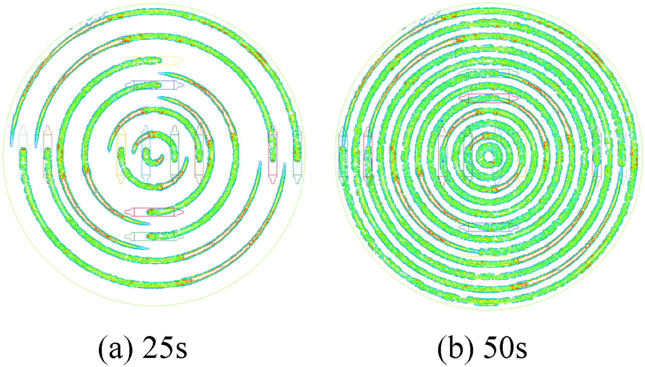
The cutting morphology of the rock in the central area of the pressurized cutterhead. (a) 25 s and (b) 50 s.

The damage cloud diagram of rock section in the central area. (a) Atmospheric cutterhead and (b) pressurized cutterhead.
During the rotary cutting process of the cutter group, the force diagram of the cutter is shown in Figure 16. Fv(vertical force), Fr(rolling force) and Fs(side force) are the three directional loads in the cutter's coordinate system, and α is the polar angle of the cutter. In the simulation model, the three-directional forces Fx, Fy and Fz acting on the cutter in the cutterhead's coordinate system xyz can be directly monitored. According to the principle of force synthesis and decomposition, the three-directional loads of the cutter can be calculated by: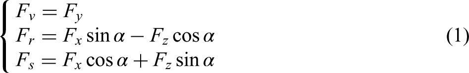

Force diagram of the cutter.
Figures 17 and 18 show the three-directional load curves of cutters for the atmospheric cutterhead and pressurized cutterhead, respectively. Due to the large number of cutters, only the CX2 and DX2 cutters from the inner ring and the CX11 and DX11 cutters from the outer ring are selected for analysis. As can be seen from the figures, the variation patterns of the three-directional loads over time are basically consistent between the atmospheric cutterhead and pressurized cutterhead. For both the vertical force and rolling force, their load curves fluctuate within a certain range, exhibiting characteristics typical of intermittent rock fragmentation. Regarding the side force, taking the side force direction shown in Figure 16 as positive, observation of the lateral force curves reveals that the side forces of the inner cutters CX2 and DX2 primarily fluctuate within a range greater than 0, while the side forces of the outer cutters CX11 and DX11 exhibit significant positive-negative fluctuations, though they still predominantly remain positive. As a result, the mean side forces of the CX2 and DX2 disc cutters are larger, which are 7.11 and 7.07 kN, respectively, while the mean side forces of the CX11 and DX11 disc cutters are smaller, which are 0.83 and 2.56 kN, respectively.
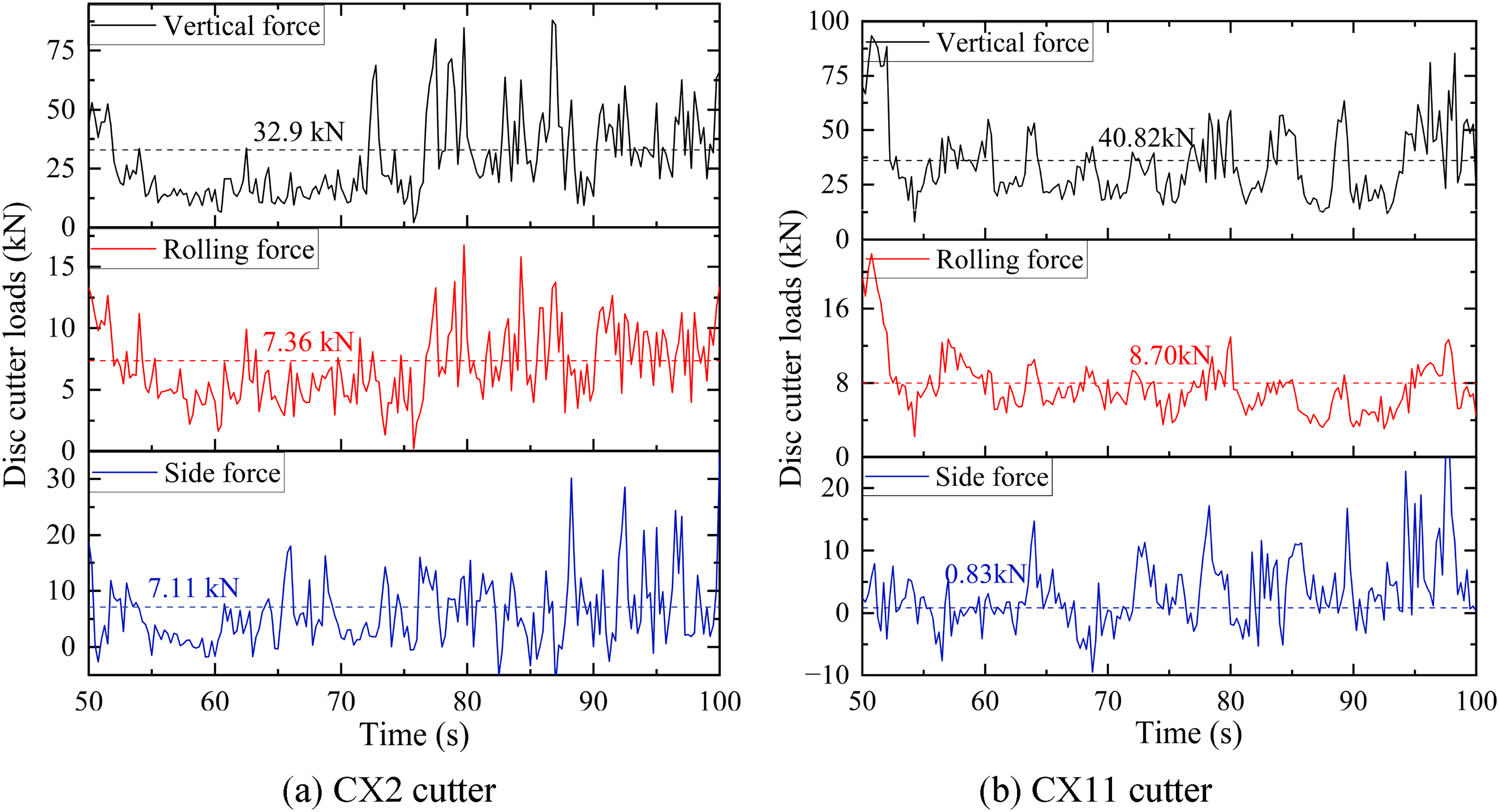
Three-directional load curves of the cutter of the atmospheric cutterhead. (a) CX2 cutter and (b) CX11 cutter.

Three-directional load curves of the cutter of the pressurized cutterhead. (a) DX2 cutter and (b) DX11 cutter.
The average load of each cutter in the central area of the atmospheric cutterhead and pressurized cutterhead is calculated, as shown in Figure 19. When the cutter group is cutting, the load on a cutter is affected by many factors such as cutting speed and the synergistic effect between the cutters. Therefore, as the cutter ID increases, that is, as the installation radius increases, the load does not change monotonically. However, from the overall trend, with the increase in the cutter ID, the vertical force and the rolling force show an upward trend due to the increase in the linear velocity. However, the side force decreases with the increase in the cutter ID, and the mean value of the side force is always positive. The reason is that during the circumferential cutting process, the front portion of the cutter will rotate to the inner side of the circumference and squeeze the inner rock to form a side force pointing to the outer side of the circumference. At the same time, the rear portion of the cutter will rotate to the outer side of the circumference, but the rear portion will not contact the rock during the cutting process, so the rear portion does not produce a side force; finally, the overall side force of the cutter will point to the outer side of the circumference. When the installation radius of the cutter is small, the curvature of the cutting trajectory is large, the lateral extrusion effect generated by the rotation of the cutter is strong, and the side force is larger. When the installation radius increases, the curvature of the cutting trajectory is small, and the circumferential cutting gradually approximates linear cutting, The lateral extrusion effect generated by the cutter rotation weakens, and the side force is reduced. Finally, comparing the vertical and rolling forces of cutters in the central area between the two cutterheads, it can be found that the vertical force and rolling force of cutters of the atmospheric cutterhead are greater than those of the pressurized cutterhead in most positions.

Mean loads of cutters in the central area of the atmospheric and pressurized cutterheads.
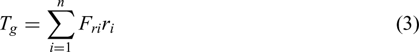
The thrust and torque of the cutter group in the central area of the atmospheric cutterhead and pressurized cutterhead are calculated, respectively. The calculation formulas are shown in equations (2) and (3), where Fg is the thrust of the cutter group, Fyi is the force of the i-th cutter in the y-axis direction of the cutterhead coordinate system, Tg is the torque of the cutter group, Fri is the rolling force of the i-th cutter, ri is the installation radius of the i-th cutter, and n is the number of cutters. The thrust and torque of the cutter group in the central area of the atmospheric cutterhead are calculated to be 424.6 kN and 84.5 kN·m, respectively. The thrust and torque of the cutter group in the central area of the pressurized cutterhead are 405.1 kN and 60.3 kN·m, respectively. The thrust and torque of the cutter group in the central area of the pressurized cutter head are smaller, the thrust is 95.5% of the atmospheric cutterhead, and the torque is 71.4% of the atmospheric cutterhead.
The specific energy of rock breaking is an important index to characterize the rock breaking efficiency and energy consumption of the cutter group. It is defined as the energy required to break a unit volume of rock. During rotary cutting by the cutter group, the specific energy of rock breaking can be calculated by
Here, SErb is the specific energy of rock breaking, x is the displacement of the cutter group along the thrust direction, φ is the rotation angle of the cutter group, and V is the volume of broken rock, which can be obtained by counting the number of failed and deleted elements in the software. The rock-breaking specific energy of the cutter group in the central area of the atmospheric cutterhead and pressurized cutterhead is calculated to be 15.04 and 14.38 MJ/m3, respectively. The rock-breaking specific energy of the pressurized cutterhead is 95.6% of that of the atmospheric cutterhead, indicating that the rock-breaking efficiency of the cutter group in the central area of the pressurized cutterhead is higher.
Comparative analysis of the cutter group in the front area
Taking the installation radius range of 6230–6995 mm as an example, the dynamic process of rock cutting in the front area of the atmospheric cutterhead and pressurized cutterhead is obtained by numerical simulation, as shown in Figures 20 and 21. It can be seen that during the process of the cutter's rock cutting, the damage area of the rock expands around the center below the blade and forms a semi-circular damage area on the rock section. By comparing the rock-cutting morphology of the two cutterheads, it can be found that in the front area of the atmospheric cutterhead, there is a complete rock ridge between the adjacent cutting trajectories; for the front area of the pressurized cutterhead, the damage areas of DZ3, DZ2 and DZ1 cutters are completely connected except that the DZ4 cutter is the first to cut and penetrates into the rock shallowly, which fails to connect with the damage area of the DZ3 cutter. This is because the cutter spacing in the front area of the atmospheric cutterhead and pressurized cutterhead is 100 and 75 mm, respectively. The cutter spacing in the front area of the pressurized cutterhead is smaller, and the synergistic rock breaking effect between the cutters is stronger.

Dynamic process of rock cutting in the front area of the atmospheric cutterhead. (a) CZ1 cutter and (b) CZ2 cutter.
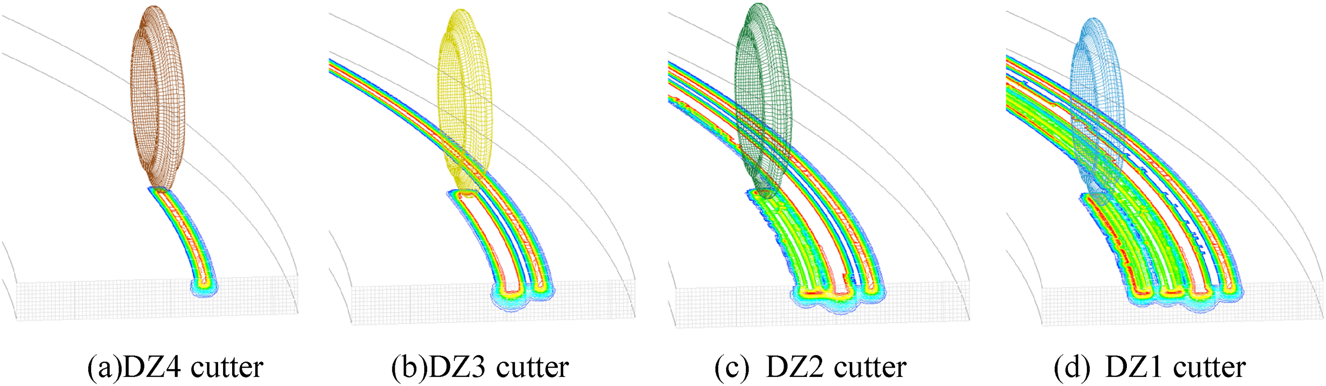
Dynamic process of rock cutting in the front area of the pressurized cutterhead. (a) DZ4 cutter, (b) DZ3 cutter, (c) DZ2 cutter, and (d) DZ1 cutter.
The three-directional loads of cutters in different radius areas of the atmospheric cutterhead and pressurized cutterhead are counted. Because the force forms of cutters in the front area and the central area are the same, equation (1) is still used to calculate the three-directional loads of cutters. Due to the installation radius of cutters in the front area being large, the side force mainly comes from the uneven crushing of rocks on both sides of the blade, and the side force is generally small, so the side force is no longer analyzed. Considering that there are two double-cutters in the atmospheric cutterhead model and four single-cutters in the pressurized cutterhead model, in order to facilitate the comparison, the total vertical force and rolling force of all cutters in each installation radius area are divided by the number of blades, and the average load of cutters in the installation radius area is obtained. The statistical results are shown in Table 3. The installation radius in the table is the average installation radius of all cutters in each area.
The average load of cutter under different radii.

The average load of the cutter at different installation radii of the atmospheric cutterhead and pressurized cutterhead is linearly fitted, and the relationship between the load of the cutter in the front area and the installation radius is obtained:


Here, Fa v and Fa r are the vertical force and rolling force of the cutter in the front area of the atmospheric cutterhead, Fp v and Fp r are the vertical force and rolling force of the cutter in the front area of the pressurized cutterhead (kN), and r is the installation radius (mm).
The load and fitting curves of the cutter at different radii of the atmospheric cutterhead and pressurized cutterhead are shown in Figure 22. The analysis shows that with the increase in the installation radius, the vertical force and rolling force of the cutter also increase approximately linearly. By comparing the loads of the two cutterheads, it can be found that the vertical force and rolling force of the cutters in the pressurized cutterhead are smaller than those in the atmospheric cutterhead.

Fitting curve of cutter load under different installation radii.
Since the number of cutter blades in the front area of the atmospheric cutterhead and pressurized cutterhead is 52 and 78, respectively, in order to facilitate the comparison of the total load of the cutterhead in the front area, the fitting equations (4)–(7) are used to calculate the load of each cutter in the front area, and equations (2) and (3) are used to calculate the thrust and torque of the cutter group in the front area. The results show that the thrust and torque of the cutter group in the front area of the atmospheric cutterhead are 1547.9 kN and 1847.0 kN·m, respectively. The thrust and torque of the cutter group in the front area of the pressurized cutterhead are 1870.3 kN and 2286.1 kN·m, respectively. The thrust and torque of the cutter group in the front area of the pressurized cutterhead are 120.8% and 123.8% of those of the atmospheric cutterhead, respectively. In summary, for the front area, the load of a single blade of the pressurized cutterhead is less than that of the atmospheric cutterhead, but the greater number of blades in the pressurized cutterhead makes the total load of the cutter group in the front area larger than that of the atmospheric cutterhead.
The specific energy of rock breaking in different radius areas of the atmospheric cutterhead and pressurized cutterhead is counted, as shown in Figure 23. The analysis shows that when the installation radius is constant, the rock-breaking specific energy of the atmospheric cutterhead is higher than that of the pressurized cutterhead, and the rock-breaking efficiency of the pressurized cutterhead is higher. For the four installation radii from small to large, the rock-breaking specific energy of the pressurized cutterhead is 94.2%, 85.0%, 83.2% and 73.4% of that of the atmospheric cutterhead, respectively. With the increase in the installation radius, the rock-breaking specific energy of the cutter group in the front area increases, and the rock-breaking efficiency decreases. The possible reason is that when the installation radius increases, the linear speed of the cutters increases, which reduces the rock-cutter contact duration and weakens the synergistic rock breaking effect between adjacent cutters. Furthermore, the increasing rate of the rock-breaking specific energy for the atmospheric cutterhead is significantly higher than that of the pressurized cutterhead, indicating that when the installation radius increases, the larger cutter spacing of the atmospheric cutterhead will make the rock breaking efficiency decrease rapidly.

The specific energy of rock breaking under different installation radii.
Comparative analysis of the cutter group in the edge area
Compared with the central and front areas, the cutters in the edge area have an installation angle, so their penetration mode and force characteristics change greatly. Figure 24 is a schematic diagram of the penetration of the edge cutter and the three-directional loads in the cutter's coordinate system. The penetration of the edge cutter can be decomposed into two components along the vertical and side directions of the cutter, and the sizes are pcosθ and psinθ, respectively, where θ is the installation angle. According to the principle of force synthesis and decomposition, the three-dimensional load calculation formula in the cutter's coordinate system can be derived, as shown in equation (9), where Fx, Fy, and Fz are the three-directional loads in the cutterhead's coordinate system.

Penetration and three-directional load of the edge cutter.
The dynamic cutting process of the cutter group in the edge area of the atmospheric cutterhead is shown in Figure 25. In the figure, CB7, CB8 and CB9 are three cutters with the same installation radius and installation angle, but different phase angles, as shown in Figure 25(b), (f) and (g). It can be seen that multiple cutting trajectories are formed on the rock surface in turn with the rotary penetration of multiple cutters, but the damage range of the rock is basically concentrated near the cutter blade, and the damage areas of adjacent cutters are not connected, leaving intact rock ridges between them.

Dynamic cutting process of the cutter group in the edge area of the atmospheric cutterhead. (a) CB3 cutter, (b) CB7 cutter, (c) CB2 cutter, (d) CB4 cutter, (e) CB1 cutter, (f) CB8 cutter, (g) CB6 cutter, and (h) CB5 cutter.
The dynamic cutting process of the cutter group in the edge area of the pressurized cutterhead is shown in Figure 26. Due to the excessive number of cutters (totaling 22), for the three groups DB9–DB12, DB13–DB16 and DB17–DB22—which share identical installation radius and inclination angles but differ in phase angles, only the cutting process of the first cutter in each group is shown in Figure 26(a), (c) and (e). It can be found that the cutting process in the edge area of the pressurized cutterhead is similar to that of the atmospheric cutterhead. The difference is that the damage of the rock between the adjacent cutters in the edge area of the pressurized cutterhead is basically penetrated, especially between the cutting trajectories of the cutters with a large installation angle. This is because the large installation angle cutter has greater penetration along its side direction (psinθ), which is conducive to the expansion of damage to adjacent cutters.

Dynamic cutting process of the cutter group in the edge area of the pressurized cutterhead. (a) DB11 cutter, (b) DB4 cutter, (c) DB21 cutter, (d) DB6 cutter, (e) DB14 cutter, (f) DB8 cutter, (g) DB1 cutter, (h) DB3 cutter, (i) DB5 cutter, (j) DB7 cutter, and (k) DB2 cutter.
Figure 27 shows the mean value of the three-directional forces in the cutter's coordinate system at different positions of the atmospheric cutterhead and pressurized cutterhead. The rectangular frame on the abscissa indicates that the cutters in the frame are cutting along the same track, such as CB6–CB8 of the atmospheric cutterhead. At the same time, for the double-cutters CB1–CB4 in the atmospheric cutterhead, in order to facilitate the comparison with other single-cutters, the three-directional loads of these four cutters are multiplied by 0.5 and then plotted in the figure. Through analysis, the following conclusions can be drawn.
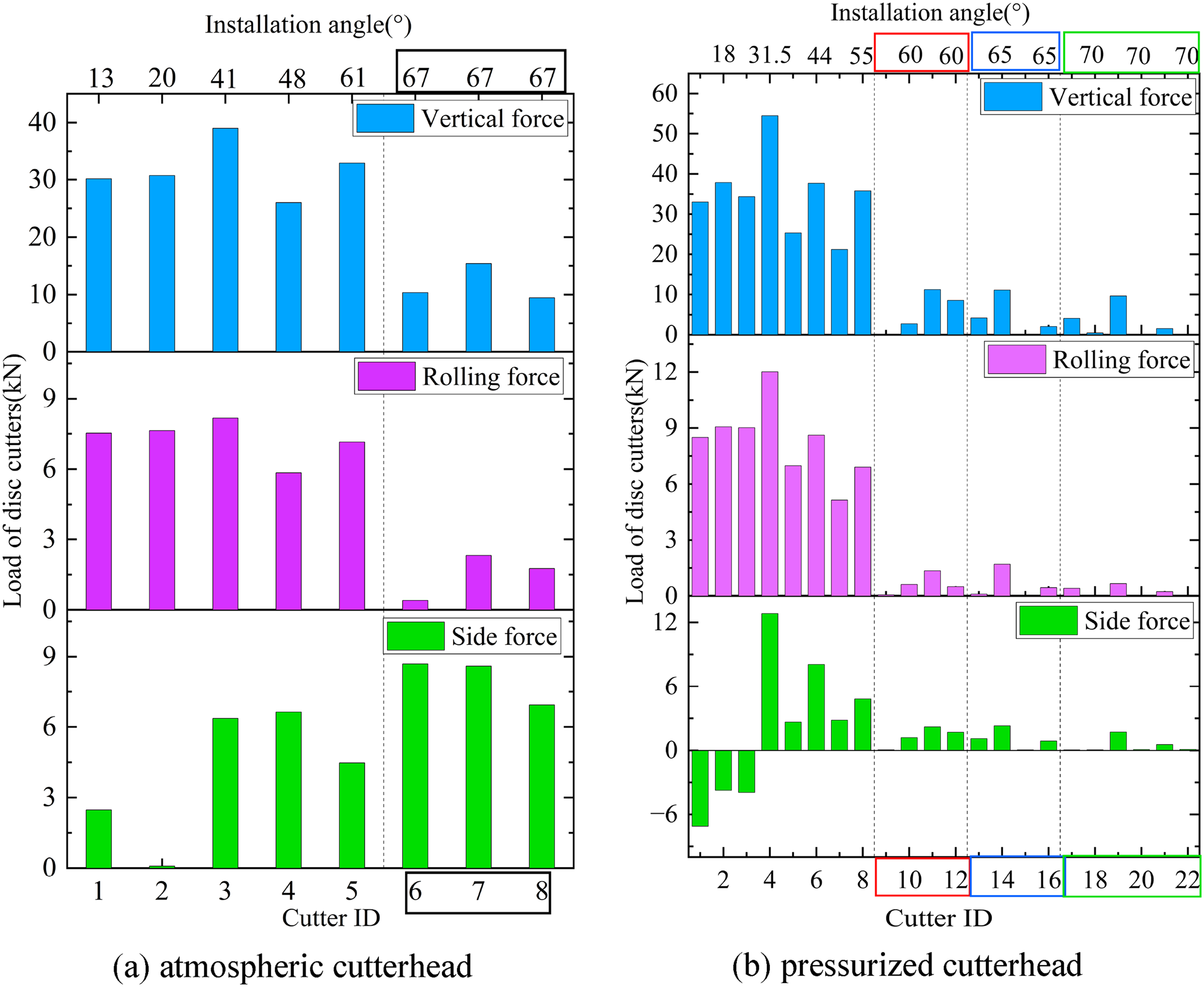
Mean loads of the cutter of the atmospheric cutterhead and pressurized cutterhead. (a) Atmospheric cutterhead and (b) pressurized cutterhead.
First, when multiple cutters cut along the same track, the vertical force and rolling force of the cutter are significantly reduced because the cutting amount of the rock is shared among multiple cutters. For example, the vertical force and rolling force of CB6–CB8 cutters of the atmospheric cutterhead are significantly lower than those of CB1–CB5 cutters. The vertical force and rolling force of DB9–DB12, DB13–DB16, and DB17–DB22 cutters of the pressurized cutterhead are significantly lower than those of DB1–DB8 cutters.
Second, the vertical force and rolling force of a cutter are related to the cutting sequence. For adjacent cutters, the vertical force and rolling force of the first cutting cutter are generally large, and the vertical force and rolling force of the second cutting cutter will decrease due to the synergistic rock-breaking effect between the first cutting cutter and the second cutting cutter. For example, in the atmospheric cutterhead, for the double-cutters CB2–CB4, due to the first cutting by CB3, its vertical force and rolling force are significantly greater than those of adjacent CB2 and CB4. In the pressurized cutterhead, for DB3–DB5 cutters, due to the first cutting by DB4, the vertical force and rolling force are significantly greater than those of adjacent DB3 and DB5 cutters. However, due to the different installation angles and installation radii of different cutters in the edge area, these factors also have an impact on the vertical force and rolling force, resulting in the magnitude of load between adjacent cutters is not completely determined by the cutting sequence.
Finally, there are some differences in the side force characteristics between the atmospheric cutterhead and pressurized cutterhead. In theory, with an increase in installation angle, the side force will increase due to the increase in side penetration (
According to equations (2) and (3), the thrust and torque of the cutter group in the edge area of the two cutterheads are calculated, respectively. The thrust and torque of the cutter group in the edge area of the atmospheric cutterhead are 285.4 kN and 506.2 kN·m, respectively, and the thrust and torque of the cutter group in the edge area of the pressurized cutterhead are 239.8 kN and 462.2 kN·m, respectively. The thrust of the cutter group of the pressurized cutterhead group is 84.0% of that of the atmospheric cutterhead, and the torque is 91.3% of that of the atmospheric cutterhead, indicating that although the number of cutters in the edge area of the pressurized cutterhead is large, the load is smaller than that of the atmospheric cutterhead.
According to equation (4), the rock breaking specific energy of the cutter group in the edge area of the atmospheric cutterhead and the pressurized cutterhead is calculated. The rock-breaking specific energy in the edge area of the atmospheric cutterhead is 16.35 MJ/m3, and the rock-breaking specific energy in the edge area of the pressurized cutterhead is 12.99 MJ/m3. The rock breaking specific energy in the edge area of the pressurized cutterhead is 79.45% of that of the atmospheric cutterhead. The results show that the rock breaking load and rock breaking specific energy in the edge area of the pressurized cutterhead are effectively reduced due to the smaller cutter spacing and the simultaneous cutting of multiple cutters along three cutting trajectories near the outer ring.
Comprehensive analysis of the entire cutterhead cutter group
From the above analysis, it can be seen that the cutting performance of the cutter group is different due to the differences in cutter spacing, cutting sequence, installation radius, number of cutters and other factors in each area of the cutterheads. The following will be a comprehensive comparison of the cutting performance of the entire cutterhead cutter group.
From the total load of the entire cutterhead cutter group, the total thrust (Fgt) and torque (Tgt) of the entire cutterhead cutter group can be calculated by:

From the load of each cutter, the thrust per cutter (Fpc) and torque per cutter (Tpc) are calculated according to equations (12) and (13):

From the point of view rock-breaking specific energy, whether it is in the center, front and edge areas, the rock-breaking specific energy of the cutter group with the pressurized cutterhead is lower than that of the atmospheric cutterhead, and the rock-breaking efficiency for the cutter group of the pressurized cutter is higher. With the increase of the installation radius, the advantage of the cutter group of the pressurized cutterhead on the rock-breaking specific energy becomes more and more significant. In the central area, the rock-breaking specific energy of the cutter group with the pressurized cutterhead is 95.6% of that of the atmospheric cutterhead, while in the front area with the largest installation radius (6230–6995 mm) and the edge area, the rock breaking specific energy of the cutter group of the pressurized cutterhead is only 73.4% and 79.4% of that of the atmospheric cutterhead, respectively.
In summary, due to the smaller cutter spacing of the pressurized cutterhead, the damage expansion and penetration effect between the cutters in each area of the pressurized cutterhead is better, and the synergistic rock-breaking effect between the cutters is stronger. Synergistic rock-breaking effectively reduces the rock breaking load on each cutter, reduces the rock-breaking specific energy of the cutter group, and inhibits the increase of rock-breaking specific energy due to an increase in installation radius. Although the thrust and torque of the entire pressurized cutterhead cutter group are slightly higher than those of the atmospheric cutterhead due to the larger number of cutters, the increase in load comes in exchange for a significant increase in rock-breaking efficiency and a decrease in single cutter load, which reduces the wear of cutters. Overall, the cutting performance of the pressurized cutterhead is better than that of the atmospheric cutterhead.
Analysis of tunneling data for two types of cutterheads
The excavation data from the 191–340 ring excavation section of the atmospheric cutterhead and the pressurized cutterhead are analyzed. As mentioned in section “Geological condition of the project,” the geology of the excavation section of the eastern and western tunnels is a single slightly weathered argillaceous siltstone. In addition, the construction tasks of the two tunnels are undertaken by the China Railway 14th Bureau Large Shield Company, which means that the construction operations and staffing are also unified. Key excavation parameters such as cutterhead speed, penetration, thrust and torque of the two cutterheads are recorded, and the excavation parameters are preprocessed and screened to facilitate subsequent processing and analysis. In the process of preprocessing and screening, the 3σ method is used to identify and exclude abnormal data points, and then the data with the tunneling speed greater than 0 are selected from all the data to exclude washing data and retain the tunneling data.
Load of each cutter
The thrust penetration index (FPI) and torque penetration index (TPI) are used to characterize the load of each cutter during the tunneling process. FPI and TPI are defined as the thrust and torque of each cutter per unit penetration, respectively. The thrust and torque of the cutterhead are normalized by dividing by the penetration p, and the influence of penetration on the thrust and torque of the cutterhead is excluded, as shown in equations (14) and (15):

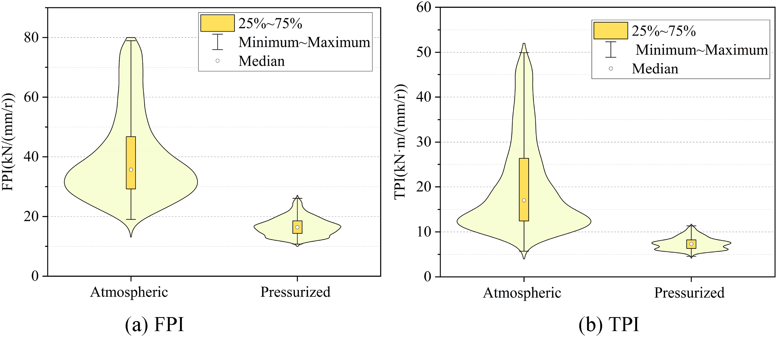
Thrust penetration index (FPI) and torque penetration index (TPI) distribution violin diagram. (a) FPI and (b) TPI.
By observing the distribution curves of FPI and TPI, it can be seen that the distribution range of FPI and TPI for the atmospheric cutterhead is wide, while the concentrated distribution range is skewed toward lower values. This shows that the load on the cutter changes greatly in the process of atmospheric cutterhead tunneling. The distribution range of FPI and TPI for the pressurized cutterhead is narrow, which is only about 1/4 of that of the atmospheric cutterhead, indicating that the load on cutters of the pressurized cutterhead is relatively stable. Further analysis of the medians of FPI and TPI shows the following: the median of FPI of the atmospheric cutterhead and pressurized cutterhead is 36.4 and 16.4 kN/(mm/r), respectively; the FPI of the pressurized cutterhead is 45.1% of that of the atmospheric cutterhead. The median of TPI of the atmospheric cutterhead and pressurized cutterhead is 17.0 and 7.4 kN·m/(mm/r), respectively, and the TPI of the pressurized cutterhead is 43.5% of that of the atmospheric cutterhead. This shows that the thrust and torque of each cutter under the unit penetration of the pressurized cutterhead are smaller, and the load is less than half that of the atmospheric cutterhead.
Tunneling specific energy
Similar to rock breaking specific energy, tunneling specific energy is an important index to characterize the tunneling efficiency and energy consumption of a shield machine, which is closely related to project cost. Tunneling specific energy is defined as the energy consumed by excavating a unit volume of rock. In the process of slurry shield machine excavation, the energy consumption of the shield machine mainly includes two aspects: the first is the thrust work, which is used to overcome the cutting resistance in front of the cutterhead, the slurry pressure on the excavation face, and the friction between the shield shell and the rock, and the second is the torque work, which is used to overcome the cutterhead cutting torque. Therefore, the tunneling specific energy can be calculated using the following equation:
The violin diagram of tunneling specific energy distribution for the atmospheric cutterhead and pressurized cutterhead is shown in Figure 29. The specific energy distribution characteristics of the atmospheric cutterhead and pressurized cutterhead are similar to those of FPI and TPI, which are not repeated here. The median tunneling specific energy of the atmospheric cutterhead and pressurized cutterhead is 45.7 and 29.2 MJ/m3, respectively, and the tunneling specific energy of the pressurized cutterhead is 63.9% of the atmospheric cutterhead, indicating that the tunneling specific energy of the pressurized cutterhead is significantly lower than that of the atmospheric cutterhead, and the tunneling efficiency of the pressurized cutterhead is higher.
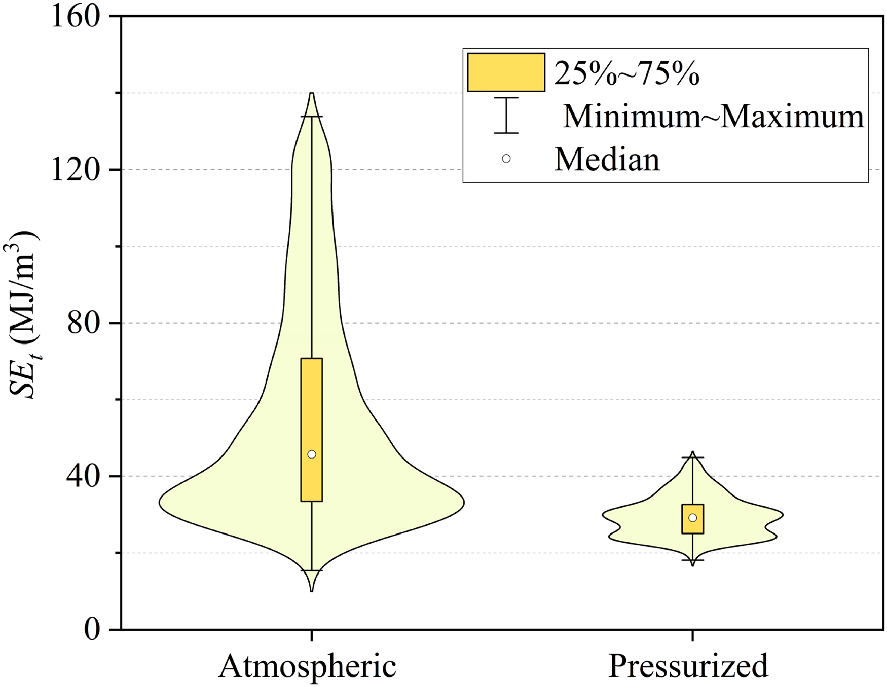
Tunneling specific energy distribution violin diagram.
Conclusion
This paper presents a detailed analysis method for the cutting performance of a super-large diameter cutterhead. Numerical models of the rotary cutting rocks by cutter groups in each area are established, respectively, based on the cutter arrangement characteristics in the central, front and edge areas of the cutterhead. The interaction characteristics between the cutter groups and the rock have been obtained in the central area, front area and edge area through analyzing the rock damage morphology, rock breaking efficiency and the spatio-temporal variation law of the cutter loads. In addition, the cutting performance of the atmospheric cutterhead and pressurized cutterhead in each area is systematically and quantitatively analyzed.
According to the results of numerical simulations, the pressurized cutterhead demonstrates better cutting performance than the atmospheric cutterhead in slightly weathered argillaceous siltstone strata. Specifically, comparative analysis across different regions shows that in the central area, the thrust and torque of the cutter group on the pressurized cutterhead are 95.5% and 71.4%, respectively, of those on the atmospheric cutterhead, while the rock breaking specific energy is 95.6% of that under atmospheric conditions. Across the entire front area, the thrust and torque for the pressurized cutterhead increase to 120.8% and 123.8%, respectively, compared to the atmospheric cutterhead. At four installation radii within the front area (from small to large), the rock breaking specific energy of the pressurized cutterhead is 94.2%, 85.0%, 83.2%, and 73.4% of that of the atmospheric cutterhead. In the edge area, the thrust and torque of the pressurized cutter group are 84.0% and 91.3%, respectively, of those on the atmospheric cutterhead, and the rock breaking specific energy is 79.45% of the latter. In summary, except for the total load in the front area—where the pressurized cutterhead exceeds the atmospheric cutterhead—the loads in all other regions are lower for the pressurized cutterhead. Moreover, the specific rock breaking energy of the pressurized cutterhead is lower across all regions, indicating higher rock breaking efficiency of its cutter group.
From the comparison results of the whole cutterhead, the load on each disc cutter blade of the pressurized cutterhead is smaller, and the thrust and torque of each disc cutter of the pressurized cutterhead are 75.7% and 78.2% of those of the atmospheric cutterhead, respectively. However, due to the larger number of disc cutters on the pressurized cutterhead, the thrust and torque of the entire pressurized cutterhead disc cutter group are 111.4% and 115.2% of those of the atmospheric cutterhead, respectively. Analysis of the rock breaking specific energy in each area shows that the rock-breaking specific energy in each area of the pressurized cutterhead is lower than in the corresponding area of the atmospheric cutterhead, indicating that the overall rock-breaking efficiency of the pressurized cutterhead is higher. In summary, due to the use of a more intensive cutter arrangement, although the total load of the pressurized cutterhead is slightly increased, the rock-breaking efficiency of the disc cutter group is significantly improved, the rock breaking load of the single disc cutter is reduced, and the consumption of the disc cutters is reduced. Therefore, the comprehensive cutting performance of the pressurized cutterhead is better.
Based on the actual tunneling data of the Haizhuwan tunnel project, the thrust penetration indices, torque penetration index and tunneling specific energy are selected as the tunneling performance indexes, and the tunneling performance of the two cutterheads in slightly weathered argillaceous siltstone strata is compared comprehensively. The results show that the thrust and torque of each disc cutter per unit penetration of the pressurized cutterhead are smaller; the FPI and TPI of the pressurized cutterhead are only 45.1% and 43.5% of those of the atmospheric cutterhead, respectively. At the same time, the tunneling specific energy of the pressurized cutterhead is only 63.9% of that of the atmospheric cutterhead, and the tunneling efficiency of the pressurized cutterhead is higher. This means that the comprehensive tunneling performance of the pressurized cutterhead is better than that of the atmospheric cutterhead, which is consistent with the conclusions of the numerical simulation.
It should be noted that the comparison of cutting performance between the two super-large cutterheads presented in this study is confined to a specific formation—micro-weathered argillaceous siltstone. Therefore, the conclusions drawn may not be directly applicable to other geological formations or composite strata. For instance, in softer rock formations, a denser arrangement of pressurized cutterheads may lead to excessive rock fragmentation. Consequently, performance comparisons between atmospheric and pressurized cutterheads under different geological conditions could yield differing results, which warrant further investigation. Nevertheless, the analytical methodology for evaluating the cutting performance of super-large diameter cutterheads can be applied to comparative studies of the two types of cutterheads under other geological conditions, where numerical simulation of rock breaking behavior by cutter groups at different zones under various other geological conditions is conducted. In the future, the selection method for the pressurized cutterhead and atmospheric cutterhead would be systematically and comprehensively analyzed, where the maintenance, cutter wear, operational downtime and cutter-changing safety are taken into consideration.
Footnotes
Acknowledgements
This work was supported by the National Key Research and Development Program of China (Grant No. 2022YFC3802300).
Author contributions
Peng Chen: writing – original draft and methodology. Shuhua Huang: writing – review and editing. Jicheng Shu: conceptualization, investigation, and validation. Ji Liu: conceptualization. Jian Sheng: methodology and conceptualization. Laikuang Lin: data curation. Mei Yang: supervision and writing – review and editing.
Funding
The authors disclosed receipt of the following financial support for the research, authorship, and/or publication of this article: This work was supported by the National Key Research and Development Program of China (grant number 2022YFC3802300).
Declaration of conflicting interests
The authors declared no potential conflicts of interest with respect to the research, authorship, and/or publication of this article.
Data availability
Data will be made available on request.