
Abstract
This study investigates the dynamic response of large-span asymmetric suspension bridges under spatially varying seismic motion, focusing on a representative bridge in Yunnan, China. A 3D finite-element model of the bridge was created using SAP2000, accounting for the sag effect of main cables and pile-soil interaction. The material nonlinearity was incorporated through plastic hinges, with critical parameters derived from XTRACT software. Based on nonlinear time history analysis under spatially varying seismic motion, the effects of spatial variability and material nonlinearity on key structural responses (shear force, bending moment, and displacement) were systematically investigated. The results indicate that considering the traveling wave effect and material nonlinearity will increase the foundation shear force and bending moment values. Under multipoint excitation, the peak longitudinal and mid-span vertical displacements are approximately 1.61 times and 1.64 times higher than those without considering the traveling wave effect and material nonlinearity, respectively. Moreover, the axial force of the suspension rod is significantly increased due to the influence of high-order modes of the bridge structure. Material nonlinearity at the tower base reduces displacement response. Neglecting these factors would underestimate earthquake effects. These findings are valuable for the design and engineering of large-span asymmetric suspension bridges.
Keywords
Introduction
The large-span bridge structure is an important traffic control point, and the structural dynamic response of large-span cable-stayed bridges, continuous rigid frame bridges, arch bridges, and symmetrical suspension bridges under earthquake action has been widely studied. 1 For example, Lin et al. 2 investigated the seismic response of long-span cable-stayed bridges under multiple cumulative continuous earthquakes, and accurately estimated the service life of cable-stayed bridges based on digital twin technology and vibration table experiments. Liu et al. 3 conducted model updating mixed experiments to reveal the seismic performance of typical reinforced concrete (RC) rigid frame thin-walled high pier bridges, and proposed a method for predicting the failure mode of thin-walled high pier bridges. Xu 4 explored the vulnerability of continuous rigid frame bridges under earthquake action based on vibration table experiments. Zhou et al. 5 proposed a method for evaluating the stability and seismic performance of large-span arch bridge deck systems.
The suspension bridges have gained widespread recognition for their structural versatility and are predominantly constructed across large rivers, deep valleys, and marine environments. Notable global examples include the innovative asymmetric single-tower self-anchored San Francisco-Oakland Bay Bridge, 6 the record-breaking Messina Straits Bridge, 7 the seismically resilient Akashi Kaikyō Bridge, 8 and the mega-scale Hong Kong–Zhuhai-Macao Bridge. 9 These landmark projects collectively exemplify the evolving trend toward super-long spans, large-span configurations, and asymmetric structural configurations in modern suspension bridge design, which have garnered increasing favor among engineers and designers for addressing complex geographical constraints.
Scholars have conducted extensive research on the seismic response of symmetrical suspension bridges. Sgambi 10 used probabilistic methods (Monte Carlo simulation) to analyze the seismic response of large-span symmetrical suspension bridges, which can take into account the variability of certain factors related to earthquake input. Wang 11 proposed a new method for optimizing the placement of dampers using penalty functions and first-order optimization theory based on the seismic response control mechanism of dampers and the seismic response characteristics of large-span symmetrical suspension bridges. The results showed that first-order optimization is an effective method for determining the optimal position of dampers. Shrestha 12 used near fault seismic motion on a 3D bridge model to investigate the response of bridges with or without vertical seismic motion under seismic motion. Use five sets of near-field ground motions with varying V/H (vertical and horizontal) ratios of peak ground acceleration. The influence of vertical motion on the overall and local structural response was proposed. Shao 13 analyzed the influence of key design parameters such as stiffening beam stiffness, tower stiffness, main cable and suspension rod stiffness, center buckle and longitudinal constraint system on the dynamic characteristics of a symmetrical suspension bridge structure. Jia 14 studied the effects of permanent fault rupture displacement, fault crossing effect, and angle on the seismic performance of suspension bridges. The study showed that the BPNN based method can accurately predict the permanent fault rupture displacement caused by fault motion 15 Jia adopted a simple and effective method to simulate the required ground motion near the fault rupture zone. By juxtaposing the generated ground motion with the observed ground motion, the accuracy and effectiveness of the proposed method were confirmed, and a detailed parameter analysis was conducted on the suspension bridge on the fault. 16 Wang investigated the influence of viscous dampers on the seismic response of long-span suspension bridges, and the study showed that different parameters of viscous dampers have a significant impact on the seismic response of long-span symmetrical suspension bridges.
The above research mainly explores the seismic dynamic response of symmetrical bridge structures, but with the development of the national transportation industry, bridges with asymmetric structural forms may appear due to the influence of terrain and other factors. Due to space limitations, this article mainly explores the structural dynamic response of asymmetric suspension bridges under spatial seismic action, providing technical reference for seismic response analysis of similar bridges.
Symmetric suspension bridges exhibit uniform static load distribution with balanced cable tensions and tower internal forces, enabling direct application of classical elastic theory, whereas asymmetric counterparts demonstrate complex static behavior due to cable length disparities and anchorage asymmetry, leading to pronounced nonuniformity in cable tension, tower deflection, and girder bending moments. Dynamically, asymmetric bridges exhibit heightened parametric sensitivity in natural frequencies (e.g. influenced by rise-to-span ratios and tower stiffness), requiring frequency estimation methods that account for span asymmetry and cable support conditions. Under multidirectional seismic excitations (torsional motion, multicomponent inputs, variable incidence angles), their dynamic responses intensify with enhanced spatial coupling effects. Notably, cable tension heterogeneity in asymmetric bridges results in significant force discrepancies between tower-side cables, with unstressed cable length growing exponentially with asymmetry parameters. Tower deflections induced by cable force imbalances necessitate saddle push-off adjustments to mitigate foundation stresses, reflecting elevated sensitivity to geometric and stiffness parameters. These complexities, arising from inherent geometric and support asymmetry, demand spatially explicit seismic response analyses to address nonlinear anchorage mechanics and ensure structural safety under coupled static-dynamic interactions.
With the passage of time, people have also developed new understandings of structural engineering, 17 such as asymmetric suspension bridges. An asymmetric suspension bridge is defined as one in which the span and structural layout are not symmetric. This asymmetry can occur due to constraints such as unfavorable terrain and geological conditions, resulting in the bridge having only one tower or unequal span lengths on either side of the tower. However, super-long span and asymmetric bridges are adopted to address the challenges of special terrains, for instance, the Osmangazi Suspension Bridge is a large sea-crossing bridge that spans the Izmit Bay. 18 Beyond geometric nonlinearity influenced by gravity stiffness and large deformation in symmetric suspension bridges, asymmetric bridges exhibit unique characteristics like internal force response, overall and local deformation, seismic design's critical points, and seismic isolation methods, 19 conversely, the Bosphorus Suspension Bridge, with its inclined hangers, can also be considered a type of asymmetric suspension bridge. 20 Additionally, high-order modes play a significant role in the nonlinear responses of asymmetric suspension bridges,21,22 and different construction phases and varying soil conditions significantly affect the structural performance of suspension bridges. 23 Soil-structure interaction extends the natural vibration period of bridge structures and heightens the likelihood of longitudinal collisions. 24 These nonlinear factors collectively contribute to a more severe moment-torsion coupling vibration phenomenon. Meanwhile, the spatial variability of ground motions, encompassing the wave-passage effect, incoherence effect, and local site effect, significantly impacts the responses of long-span and asymmetric suspension bridges. This variability may either magnify or diminish the responses of long-span suspension bridges under strong ground motions25,26 crossing potential active fault.27,28 In seismic analysis of long-span and asymmetric suspension bridges, the nonuniform seismic excitation method should be employed to model the spatial variability of ground motions. Several studies have focused on the nonuniform seismic excitation method, 29 accounting for the spatial variability of ground motions. For instance, using random vibration theory, Said employed the response spectrum analysis method to examine the partial coherence effect on a long-span cable-stayed bridge under multisupport seismic excitations30–32 and pulse-type ground motions. 33 Nurdan examined the nonlinear structural behavior of the Fatih Sultan Mehmet suspension bridge under spatially varying earthquake excitations. 34 Zhang and Jia developed an efficient method for analyzing the random seismic responses of high-pier railway bridges under three-dimensional, multipoint, nonstationary excitation.35–37 Therefore, the spatial variability of ground motions is crucial and cannot be overlooked in the seismic analysis of long-span bridges, particularly asymmetric suspension bridges.
While extensive research has been conducted on long-span and symmetrical bridges under spatially varying ground motions, limited studies focus on long-span and asymmetrical suspension bridges, particularly regarding geometric, material, and soil nonlinearity.38,39 Generally, bridge structures use steel bars and concrete, modeled as ideal elastic–plastic materials. Fiber beam-column elements are commonly employed to account for the nonlinear effects of materials in finite-element software. Adanur et al. conducted a comparative analysis of the effects of near-fault and far-fault seismic motions on the geometrically nonlinear seismic behavior of suspension bridges. 40 Elastic–plastic analysis of pile groups and single piles under three-dimensional seismic excitation was performed, focusing on the nonlinearity of foundation soil, and an elastic–plastic soil layer model was proposed. 41 Adanur et al. also investigated the impact of local site effects on the seismic response of suspension bridges. 42 This indicates that soil layer nonlinearity significantly influences the response of pile foundations to excitations with frequencies below 0.6 Hz. Parameter analysis of rigid-arch bridges under cyclic loads was conducted using an elastic–plastic finite-element model, and an empirical equation to estimate the range of seismic damage was proposed. 43 In summary, few attempts have been made to conduct nonlinear dynamic analysis of long-span and asymmetrical suspension bridges subjected to spatially varying ground motions, 44 a crucial aspect for understanding their mechanical behavior in recent years.
The increasing demand for insights into the nonlinear behavior of long-span and asymmetrical suspension bridges under spatially varying ground motions has intensified in bridge engineering. Based on the literature review and analysis above, in order to enrich the new knowledge system of seismic response analysis of long-span suspension bridges, this research, in addition to reviewing studies on such bridges, investigates the nonlinear dynamic behavior of an actual bridge in Yunnan Province, China, under spatially varying ground motions. The study comprehensively considers geometric and material nonlinearity, pile-soil interaction, and the gravity stiffness correction equation. The paper briefly introduces the ground motion synthesis method for subsequent dynamic response analysis. Concurrently, it details the basic theory for solving the equation of motion and the concept of the plastic hinge. Ultimately, the nonlinear analysis of the bridge accounts for the wave-passage effect, geometric and material nonlinearity. The study draws important conclusions in the context of the published literature, providing numerical and theoretical support to seismic codes and specifications.
General theory
Equation of motion for structures subjected to multisupport seismic excitations and its solution
Generally, the response spectrum method, a pseudodynamic approach for approximating a structure's maximum dynamic response, is used in the dynamic analysis of structures under multipoint seismic excitations due to its high efficiency. However, this method cannot accurately depict the time history of structural responses and is limited to the linear elastic range. In China, where seismic activity is intense, elastic–plastic and nonlinear characteristics significantly emerge in the dynamic behavior of long-span bridges under ground motion excitations. The time history method, a sequential dynamic analysis approach, is widely used to capture the nonlinear behavior of structures, serving as a supplementary or alternative method. Consequently, this study emphasizes the time-history analysis method for multisupport excitation.
Assuming a bridge structure with m ground supports and n degrees of freedom, the equation of motion is expressed as follows:
45

Here,
By manipulating the second block row of equation (1) through matrix operations, the following result is obtained:


The Newmark method, as the earliest technique for dynamic solutions, forms the basis for several modified methods in this field. Furthermore, the HHT method, developed by introducing an additional coefficient α, modifies the structural dynamic equation based on the Newmark method.
47
The modified dynamic equation is expressed as follows:

Implementation of multisupport seismic excitation method in general finite-element software
To account for the impact of ground motion's spatial variability on structural responses, the multisupport seismic excitation method-encompassing the large mass method, large stiffness method, and absolute displacement input method-has been developed. This method, from theory to application in general finite-element software, addresses varying seismic inputs at each ground support point of bridges.
Large mass method
Currently, the large mass method is widely implemented in the multisupport seismic excitation method within general finite-element analysis. 48 The well-known main steps of the large mass method in SAP2000 include: (1) Perform static analysis of the bridge model to determine the constraint force at each support point. (2) Remove the constraint condition in the direction of seismic excitation and apply the constraint force from step (1) to the corresponding position. (3) Apply a large mass M0 (typically about 106 times the total structural mass) to each support point. (4) Perform nonlinear dynamic analysis of the structure under multisupport seismic excitations.
The principle of the large mass method is schematically illustrated in Figure 1(a). Additionally, the time-history force applied to the released support point, resulting in the constraint, is determined as follows:


Schematic of multisupport excitation.
Once the virtual mass

The damping factors can be described as


Rooted on the equation (9), it is expected that the acceleration of structure at support point is equal to the ground acceleration at support point of structure.
Large stiffness method
The large stiffness method represents an alternative method to implementing the multisupport seismic excitation method in general finite-element software. A spring possessing a large stiffness K0, quantified as 10⁶ times the maximal element stiffness, is utilized and installed at the support point for multiple support inputs of ground motions.
49
The fundamental operational steps of the large stiffness method include:
Remove the translational constraint at the support point for the application of displacement time history; Install a spring with large stiffness at the foundation's corresponding excitation degree of freedom; Transform the acceleration time history into the displacement time history, which is then applied to the end of the spring in use; Perform displacement-based dynamic analysis on structures subjected to multisupport seismic excitations.
The solution principle of the large stiffness method is essentially identical to that of the large mass method, except that it alters the total stiffness matrix of the structure. The large stiffness method is depicted schematically in Figure 1(b).
Absolute displacement input method
The absolute displacement input method activates numerous high-frequency modes and necessitates smaller time integration increments, making it more apt for multisupport seismic excitation analysis in structures compared to acceleration input. 50 Additionally, the displacement time history at the support point, as depicted in Figure 1(c), can be directly applied in SAP2000 without special modification of the model's boundary conditions, facilitating implementation in finite-element software.
Expanding the first block row of equation (1), one can obtain as


The term of
Discussion of input method on seismic excitation
While the large mass method, large stiffness method, and absolute displacement input method offer convenience in general finite-element software, they must meet specific conditions for multisupport seismic excitation analysis. The large mass and large stiffness methods alter the mass and stiffness matrices in the structural system's equation of motion. The acceleration time history in the large mass method is adjusted to obtain a more realistic seismic response of the structure. Additionally, both the large stiffness and absolute displacement-oriented methods rely on displacement-oriented input for seismic analysis of structures. As anticipated, the displacement-oriented method in seismic analysis activates numerous high-order modes that may be overlooked in the mode superposition method. Therefore, theoretically, the displacement-oriented input mode should be more accurate than the acceleration-based method in dynamic analysis. However, ground motion records during earthquakes are typically measured conveniently using accelerometers, which experience less interference or noise from other vibrations. Most displacement time histories are derived by integrating the measured acceleration time history twice. Despite numerous baseline adjustment methods,51,52 the integration process can still deviate from the actual displacement time history. Consequently, based on the authors’ knowledge, using the large mass method is relatively reasonable and convenient for multisupport seismic excitation analysis of structures.
The suspension bridge discussed in this paper is a long-span structure, necessitating the consideration of the wave-passage effect due to the spatial variability of ground motions. Additionally, the coherence effect will be disregarded due to its minimal influence on long-span bridges, as supported by Soyluk and Tian et al.53,54 In this analysis, the apparent wave velocity is assumed to be 500 m/s. The relative arrival time at different piers is calculated by dividing the horizontal distance between adjacent support piers by this apparent wave velocity.
The theory of seismic synthesis
Accurate seismic input in dynamic analysis is crucial for ensuring the precision of structural response assessments. Consequently, seismic wave synthesis technology plays a vital role in seismic analysis. This study includes a brief introduction to seismic wave synthesis as a precursor to the detailed elastic–plastic analysis of a long-span suspension bridge subjected to ground motions. Initially, the acceleration response spectrum and peak bedrock values are used as synthetic targets, with the time history on the bedrock synthesized through a numerical simulation method.
55
The fundamental processes of ground motion synthesis, commonly employed in engineering seismology, are outlined as follows:
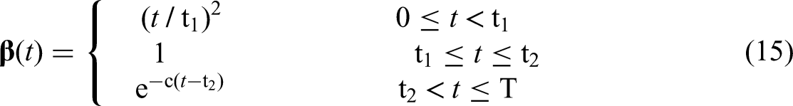
The target response spectrum is converted into the corresponding power spectrum using the following equation (12): A stationary Gaussian process with a zero mean is generated using the trigonometric series superposition method: Multiply the stationary time history by the nonstationary strength envelope function β(t) to obtain the nonstationary acceleration time history. The nonstationary envelope function takes the following form:
where
where
in which


To satisfy the accuracy requirement, the amplitude is iteratively adjusted according to the following equation (16):

Numerical examples
The long-span suspension bridge background and its finite-element model
The long-span suspension bridge background
This study investigates the nonlinear dynamic response of steel–concrete composite structures, specifically focusing on a typically asymmetric, long-span, single-tower suspension bridge. This bridge, featuring a span arrangement of 2 × 40 m + 780 m, is located in Yunnan Province, China, and is subject to spatially varying ground motion. The asymmetry refers not to structural span asymmetry, but rather to asymmetry in the structural system. Specifically, this manifests as the presence of a bridge tower on one side and the absence of a bridge tower on the other side, with the latter replaced by a tunnel-type anchorage, thereby creating an asymmetrical configuration in the structural system. The long-span suspension bridge in question (illustrated in Figure 2) spans a V-shaped canyon, predominantly surrounded by carbonate hard rock soil on both sides. The portal frame tower, standing at 156 m, consists of double columns with variable cross-sections, narrowing from 9.0 m in width at the tower's base to 6.0 m at the top, and similarly, from 9.0 m to 7.0 m in length along the bridge. Additionally, the tower wall maintains a uniform thickness of 100 cm throughout its height. The tower column is equipped with an upper crossbeam (cross-sectional dimensions: 6 m × 5 m) and a middle crossbeam (cross-sectional dimensions: 7 m × 6.5 m). The steel main cable, comprising 91 high-strength steel wires, each 5.0 mm in diameter and with a nominal tensile strength of 1860 MPa, bears loads from the deck, such as vehicles, pedestrians, and wind, transmitting these loads to the main tower. Tunnel anchors are adopted at both ends of the main cables. Suspender A, depicted in Figure 2, comprises 91 steel wires, each 7.0 mm in diameter, while Suspender B consists of 109 steel wires, each 5.0 mm in diameter, both with a nominal tensile strength of 1860 MPa. The steel box stiffening girder, measuring 31.4 m in width and 3 m in height, features a 2% slope in the transverse direction. Furthermore, to restrict the longitudinal displacement of the main girder during earthquakes, two nonlinear viscous damper at the ends of the girder near the tunnel portal (as shown in Figure 2). To provide a solid base, the bridge employs a pile group foundation, comprising a cushion cap measuring 21.6 m × 21.6 m and round cast-in-place piles with a diameter of 2 m.

Basic information of the long-span suspension bridge.
Finite-element model
Modelling of long-span suspension bridges
The finite-element model of the bridge under consideration is created using the nonlinear finite-element software SAP2000. In SAP2000, the stiffening girder, tower, and pile foundation are simulated using frame elements. Additionally, a special cable element is used to model the main cable and suspenders. The damper connection element, following the Maxwell calculation model, simulates the nonlinear viscous dampers installed between the tower's middle crossbeam and the girder, as well as at the ends of the girder near the tunnel portal. The detailed configuration of the dampers is illustrated in parts A and B of Figure 3. The main parameters of the finite-element model in Figure 3 are shown in Tables 1 to 3. Additionally the unit weight of concrete is 26 kN/m³, the unit weight of asphalt concrete used for bridge decking is 25 kN/m³, and the unit weight of the metal railings on the bridge deck is 78.5 kN/m³.
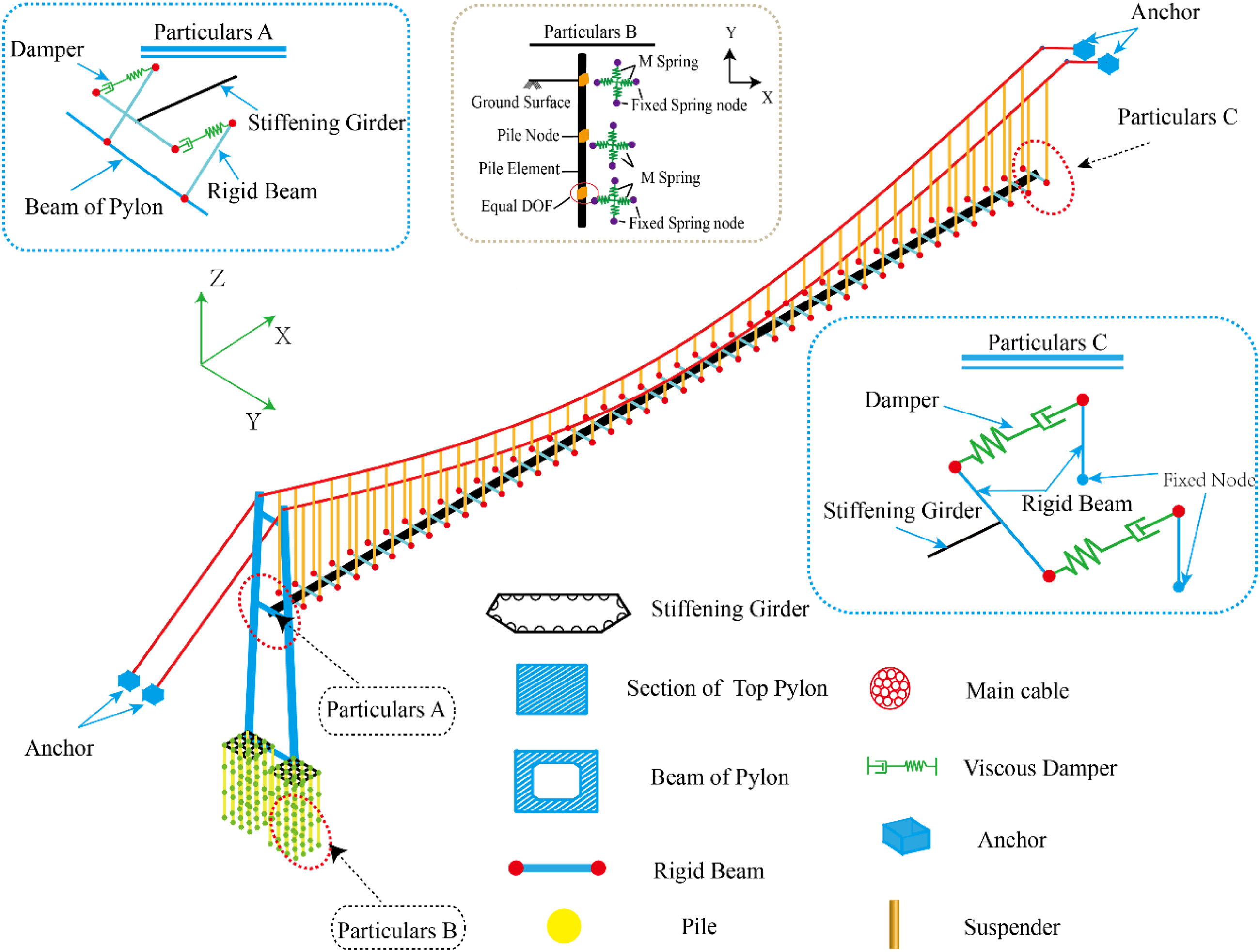
Finite-element model.
Stiffening girder parameters in Particulars A and C.

Parameters of dampers.

Soil spring parameters in Particulars B.

The anchor ends of the main cables and the bottoms of the piles are fixed in all degrees of freedom. The complete finite-element model, as shown in Figure 3, comprises 565 nodes, 200 connection elements, 271 frame elements, and 246 cable elements.
The main cable of a long-span suspension bridge is a flexible system, and under the self-weight of the main cable, its geometric shape will undergo significant changes. The stiffness of the main cable after the shape change no longer conforms to the current relationship, but exhibits obvious geometric nonlinearity. The geometric nonlinearity of the main cable of a long-span suspension bridge caused by the sag effect can be considered by modifying the elastic modulus of the main cable, and the correction formula is:
35

Pile-soil interaction modelling
Pile-soil interaction plays a notably important role in the dynamic response of structures, especially under conditions of relatively soft soil foundations. Numerous efforts have been made to develop various simulation methods, such as the P-y curve method, K method, m method, and C method, for modeling pile-soil interaction.56,57 The P-y curve method, primarily employed in Port Engineering in China, is capable of modeling the nonlinear lateral resistance of soil around a pile. The remaining three methods (K method, m method, and C method) are designed for calculating the elastic resistance coefficient of the soil. However, in the K method, the elastic resistance coefficient remains constant, while in the M method, it exhibits linear variability, and in the C method, it undergoes nonlinear changes with increasing pile depth. Due to its relatively rational and efficient characteristics, the M method will be employed in this study to account for pile-soil interaction. In the M method, 45 the soil spring stiffness (ksoil) of each soil layer is determined by the formula ksoil = a × b1× m × z, where a represents the thickness of the buried soil layer, b1 is the width of the pile, m is the proportional coefficient of the horizontal resistance coefficient of the nonrock foundation, and z is the vertical distance from the calculated point to the surface.
The calculated width of the pile can be obtained as

Plastic hinge modeling
To simplify, concentrated plastic hinges are extensively utilized to model the plastic behavior of flexural members in bridge engineering. They are typically positioned at the base of the tower, where maximal moment responses are observed in time history analyses. The attributes of the plastic hinge are defined by parameters derived from moment curvature analysis, such as Mn (Ultimate state moment), Myi (Initial yield moment), φyi (Initial yield curvature), φy (Equivalent yield curvature), φu (Limit yield curvature), and εcu (Ultimate strain of concrete). Additionally, the middle crossbeam of the tower is particularly susceptible to the formation of plastic hinges. Consequently, PMM plastic hinges, which represent the coupled hinge of axial force (P), moment along the Y-axis (My), and moment along the Z-axis (Mz) in SAP2000, are assigned to the elements at both the base and the middle crossbeam of the tower (refer to Figure 3).
Typical concrete cross-sections are modeled using three distinct material models: unconfined concrete (Cover), confined concrete (Core), and the longitudinal reinforcing steel model. The characteristics of unconfined concrete are generally reflected in its material stress-strain relationship. Essential parameters of unconfined concrete include the crushing strain, where excessive cracking initiates followed by a rapid strength degradation to the spalling strain, and the spalling strain, where concrete stress transitions to post-crushing strength. Typically, the values for crushing and spalling strain in unconfined concrete are 0.004 and 0.006, respectively. Additional parameters encompass post-crushing strength (0), 28-Day compressive strength (26.8 × 10³ kPa), tensile strength (0), crushing strain (4 × 10⁻³), spalling strain (6 × 10⁻³), yield strain (1.4 × 10⁻³), among others. In confined concrete, owing to the constraint of transverse reinforcement (such as rectangular hoops), the Mander model, with a significant allowable crushing strain of 11.31 × 10⁻³, is employed. Additional parameters for confined concrete include 28-Day compressive strength (26.8 × 10³ kPa), yield strain (3.75 × 10⁻³), confined concrete core strength (32.52 × 10³ kPa), and concrete elastic modulus (3.25 × 10⁷ kPa). As per China's code, the longitudinal reinforcing steel model (Bilinear model) parameters include yield stress (3.35 × 10⁵ kPa), fracture stress (4.9 × 10⁵ kPa), strain at the onset of strain hardening (0.01), failure strain (1.0), and steel elastic modulus (2.0 × 10⁸ kPa). Due to space limitations, only the curvature curves of two sections along the bridge direction are presented, as shown in Figures 4 and 5, respectively.

Fiber section and corresponding moment curvature curve.

Fiber cross-section and moment curvature curve of section 2#.
According to the moment-curvature analysis of sections 1# and 2#, the ratios of ultimate moment to yield moment are 1.156 and 1.289, respectively. Additionally, plastic hinge skeleton curves are determined and presented in Figure 6, with key points labeled as follows: A-origin point; B-yield point; C-ultimate bearing capacity; D-participating strength; E-complete failure. While only the values of points B and C are obtainable from the moment–curvature analysis, the default values for both D and E are set at 0.2 for safety reasons.
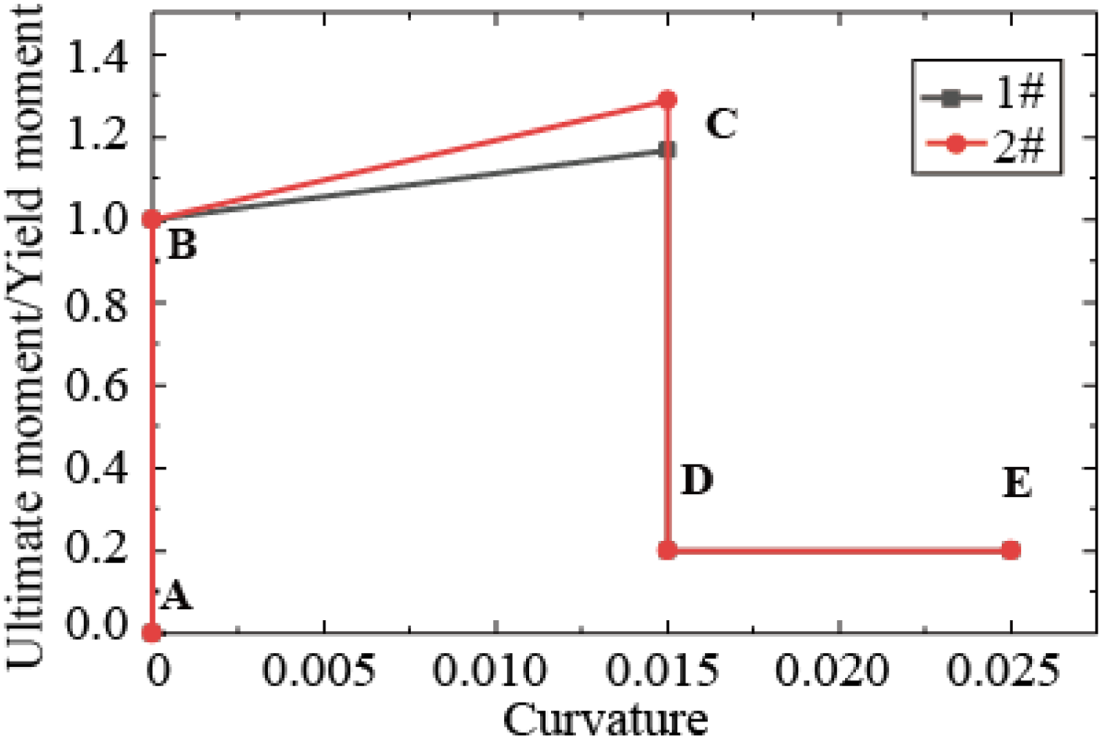
Skeleton curve of plastic hinge.
Assuming that the ultimate curvature 
The equivalent plastic hinge length Lp is closely related to the development of plastic deformation and ultimate compressive strain. Due to the large variability of experimental results, empirical formulas are currently mainly used to determine it.
Another crucial parameter, the plastic hinge length Lp, is defined according to the ‘Detailed Rules for Seismic Design of Highway Bridges’ (JTG/T B02-01-2008) by the Ministry of Transport of the People's Republic of China (2008).
58


In addition, due to the strong geometric nonlinearity of long-span suspension bridges and the possibility of the pier bottom section entering a plastic state under high-intensity earthquakes, a composite finite-element model considering the geometric nonlinearity of the main cable and the plastic deformation of the pier bottom is established to simulate the actual stress situation. The process of establishing the composite model is as follows:
① Firstly, input the parameters of the reinforcement and concrete at the bottom of the pier in the Extract software, and analyze the bending moment curvature of the pier bottom section to obtain the basic parameters of the plastic hinge that can reflect the nonlinear behavior of the pier bottom section. ② Secondly, modify the plastic hinge length of the pier bottom section in the finite-element model, and establish a geometric nonlinear model that can consider the geometric nonlinearity of the main cable based on the modified elastic modulus of the main cable. ③ Finally, applying seismic excitation to the modified finite-element model yields a composite finite-element model.
Brief introduction to seismic inputs and analysis cases
Display of synthetic ground motions
Following the ground motion synthesis process outlined in section “The theory of seismic synthesis,” seven artificial acceleration time histories are synthesized and depicted in Figure 7, featuring a time interval of 0.02 s and 2048 discrete points. Additionally, the fitting relative error is maintained below 5%. As per the zoning map of ground motion parameters in China (GB 18306-2015), the characteristic period of the ground motion response spectrum is 0.45 s, with a peak acceleration value of 0.20 g, corresponding to a basic earthquake intensity of 8°. Acceleration records are artificially synthesized and utilized. Firstly, seismic design codes in various countries are based on acceleration design response spectra. Secondly, in actual earthquakes, the recorded accelerations, which are more reliable, are commonly used. Velocity and displacement records are more susceptible to environmental noise, leading to inaccurate results.
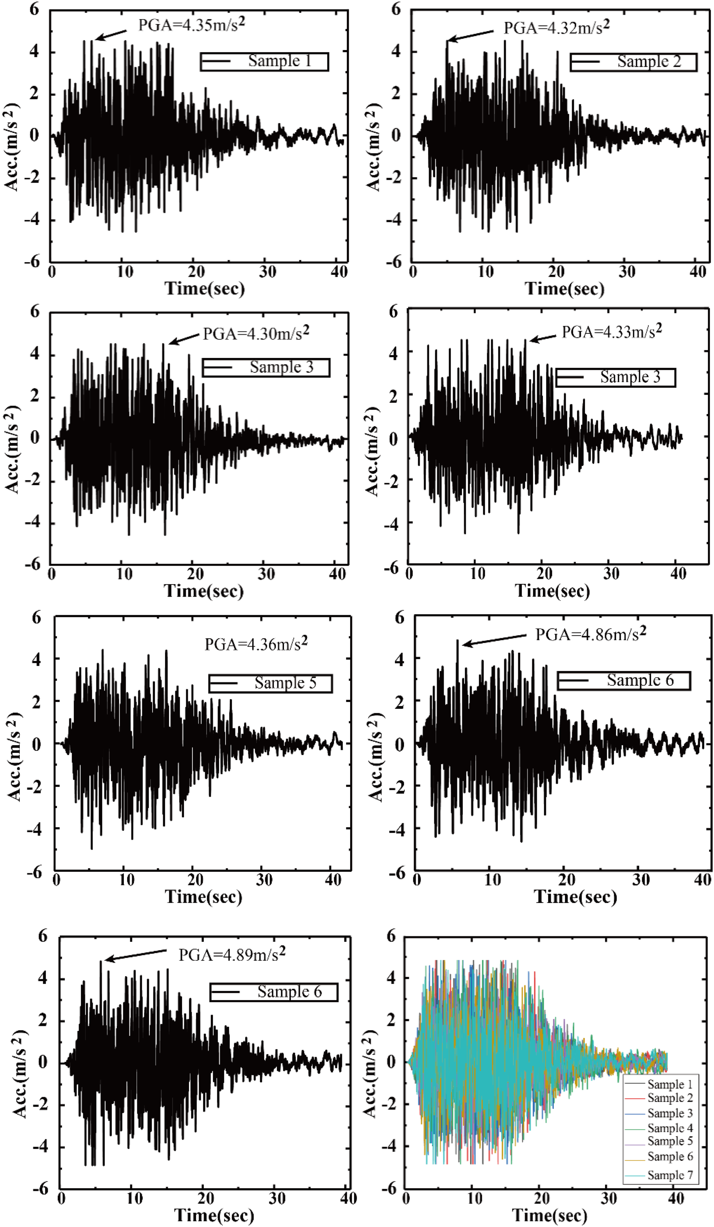
Time history of ground motion.
Cases
This study presents an analysis case in Table 1 to investigate the nonlinear dynamic response characteristics of steel–concrete composite structures, like long-span suspension bridges, under spatially varying ground motion. Specifically, the elastic model in Cases 1 and 2 is used to examine the effects of uniform and nonuniform excitation (i.e. the spatial variability of ground motion) on the suspension bridge. Similarly, the elastic–plastic model is employed in this analysis. Additionally, the material nonlinearity of the bridge is addressed in Table 4.
Analysis cases.

Numerical results and discussion
Modal analysis
Modal analysis 59 is the foundation of subsequent dynamic analysis, so the natural vibration characteristics of the bridge structure will be analyzed first. Due to the linear nature of modal analysis, the SAP2000 finite-element software automatically ignores nonlinear issues when conducting modal analysis on the aforementioned nonlinear finite-element model.
. In modal analysis, the natural frequency and resulting mode shape are determined, which aids in defining Rayleigh damping and estimating the stiffness of the long-span suspension bridge, among other things. Generally, two primary methods are used for modal analysis in SAP2000: the eigenvector method and the improved Ritz vector method (LDR method). In the eigenvector method, the mode shape is determined based on the loads, without considering the spatial effects of these loads. However, this method has low computational efficiency and often struggles with convergence. On the other hand, the LDR method circumvents errors caused by high-order mode interception, as the LDR vector consistently represents a linear combination of accurate eigenvectors. Consequently, this paper employs the LDR method for modal analysis.
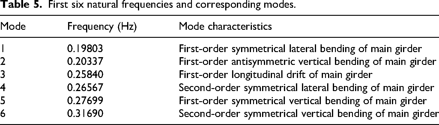
In addition to the structure's self-mass, the mass resulting from the transformation of secondary dead load is also incorporated in the dynamic analysis to more accurately simulate torsional effects. Subsequently, the modal analysis is performed using SAP2000. Due to space limitations, only the first six frequencies and mode shapes are displayed in Table 5, with the modal shapes detailed in Figure 8. As indicated in Table 5 and Figure 8, the main girder's vibration is excited in the first six orders due to its flexibility relative to the towers and the weak lateral constraints from the suspension bridge's suspenders. Additionally, the second-order symmetrical vertical bending of the main girder in the sixth-order mode, as shown in Table 5, is accompanied by the longitudinal vibration of the tower. This indicates that the coupled vibration of the tower and main girder is excited in the sixth mode.

Modal shapes.
First six natural frequencies and corresponding modes.
In seismic analysis of complex high-rise buildings and long-span structures, 60 the modal participation mass is a crucial metric for determining if the vibrations modeled in finite-element software accurately represent the structure's actual dynamic behavior. The modal participation mass coefficients in three directions (UX, UY, and UZ) are presented in Figure 9. Figure 9 shows that a mass participation coefficient of 0.35 in the UY direction indicates the contribution of the first mode to the entire structural vibration in that direction, while the coefficients for both UX and UZ are zero. In the dynamics of structures, if the modal participation mass coefficient exceeds 90%, the corresponding number of modes can accurately reflect the structure's vibration characteristics. According to Figure 9, the modal participation mass coefficients in UX, UY, and UZ are 93%, 91%, and 24%, respectively. To meet the requirement of having modal participation mass coefficients exceeding 90% in each vibration direction, the first 20 modes are selected in this study.
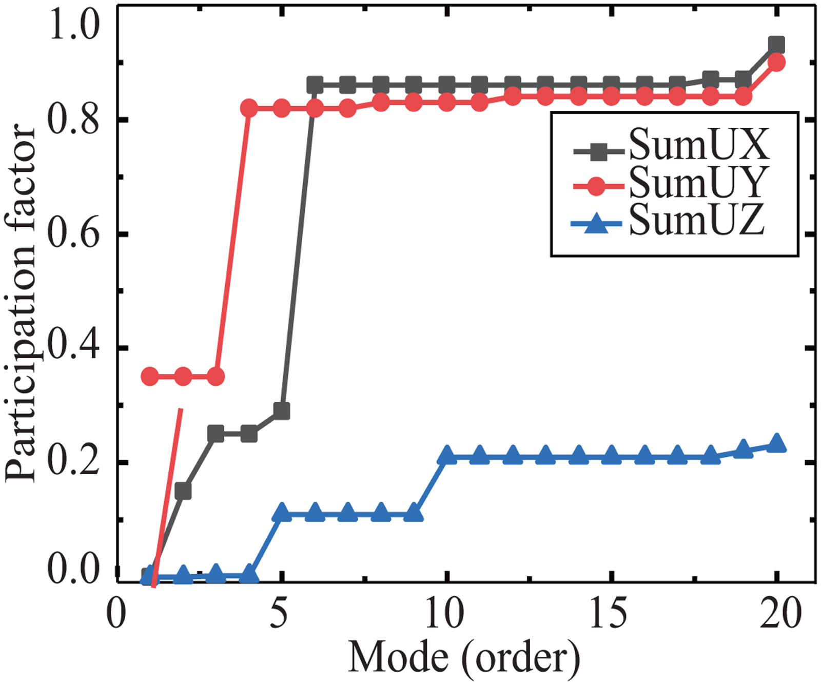
Cumulative modal participating factor.
Responses of structures and discussion
Shear force and moment responses
The comparison between the seismic peak bending moment and shear force obtained from numerical simulation and the design values is shown in Table 6. Generally, the internal force responses considering multisupport seismic excitation and the elastic–plastic material model are larger than those that do not account for nonuniform seismic excitation and material nonlinearity. Specifically, the shear force and moment responses in Case 2 are greater than in Case 1. This is attributed to the consideration of spatial variability in ground motion in Case 2, which excites numerous symmetrical and antisymmetrical vibration modes in the suspension bridge. However, uniform seismic excitation can also excite antisymmetrical vibration modes in the suspension bridge due to the load antisymmetry inherent in uniform seismic excitation. Furthermore, a comparison of responses in Cases 1 and 3 is conducted to examine the influence of material nonlinearity on the responses of interest. As observed in Table 6, comparing Cases 1 and 3, material nonlinearity leads to an increase in internal force response. However, the comparison between Case 4 and the other three cases reveals that the internal force response in Case 4 may be larger or smaller than in the other cases. Consequently, it is exceedingly challenging to assess, both quantitatively and qualitatively, the extent of influence exerted by material nonlinearity and the spatial variability of ground motion due to the complexity and comprehensiveness of plastic analysis.
Peak value responses of shearing force and moment at the bottom of tower.

Note: S-22 and S-33 represent the shear force along the local 2-axis and 3-axis directions, respectively, while M-22 and M-33 represent the moments along the local 2-axis and 3-axis directions, respectively.
In addition, analyzing Table 6 shows that the errors between the bending moment and shear force values at the bottom of the tower under the four calculation conditions and the design values are relatively small, indicating that the numerical simulation results in this paper are reliable.
Displacement responses
As anticipated, in the seismic analysis of many flexible long-span bridges, particularly steel–concrete composite and long-span suspension bridges, the longitudinal displacement response is stringently controlled. This is to prevent collision with the approach bridge and to limit displacement within the operational range of the nonlinear viscous damper installed between the main girder and the tower's middle cross beam. Additionally, the mid-span vertical displacement of the main girder reflects the level of linear control in the design of the long-span suspension bridge, considering the impact of both dead and seismic loads. Consequently, this study examines both the longitudinal and mid-span vertical displacements of the main girder. As indicated in Table 7, Cases 1 and 2, the longitudinal displacement of the main girder under nonuniform seismic excitation increases by approximately 60% compared to that under uniform seismic excitation. Simultaneously, the mid-span vertical displacement of the main girder also increases by about 60%, and the multisupport seismic excitation which can induce numerous vibration modes in the structure. Regarding the plastic constitutive effect, the influence of the plastic constitutive model on the displacement responses is more significant than that of nonuniform seismic excitation, as observed in Cases 1, 2, and 3. However, the displacement responses in Case 4 show a sharp decline compared to those in Case 3. This phenomenon can be attributed to the markedly different dynamic behaviors of structures in the elastic and plastic stages and the spatial variability of ground motion, which, conversely, leads to reduced displacement responses in Case 4. Therefore, this underscores the nature of material nonlinearity and the critical role of spatial variability of ground motion in the seismic analysis of long-span suspension bridges.
Longitudinal and vertical displacement responses of main girder (m).
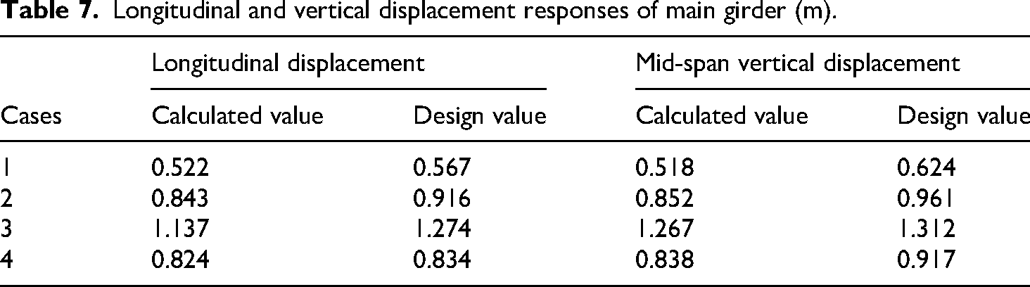
According to Table 7 analysis, the calculated values of longitudinal displacement and mid-span vertical displacement under the four working conditions are slightly lower than the design values. This is because the structural stiffness was reduced to ensure safety during the design process.
Axial force responses of stayed cables
Additionally, the main cable, modeled using cable elements, is a major load-bearing component that transmits the main girder's load to the tower in a suspension bridge system. The dynamic response of the main cable under seismic excitation is extremely complex, particularly when considering nonuniform seismic excitation and material nonlinearity. Figure 10 shows the variations in axial force of the suspension bridge's main cables. The bridge has only two main cables, which are symmetrical, meaning their axial forces are very similar. Therefore, the average of the axial forces from both cables is used to represent the main cable force in Figure 10. The axial force responses of the suspension bridge are presented in Figure 10. As indicated, the axial force in Case 1 is the smallest among all cases, particularly when considering the uniform seismic excitation and elastic model, which tend to underestimate the main cable's axial force response. Of all the cases, the axial force response is largest in Case 3. It can be inferred that for this suspension bridge, the axial force response in the elastic model is most severe under uniform seismic excitation. Furthermore, using the results of Case 3 in seismic design is relatively conservative. Additionally, in the elastic–plastic model (Cases 3 and 4), the same pattern as the internal force response observed in Tables 3 and 4 is evident. Therefore, the partial mutual offsetting of multiple vibration modes, excited by the nonuniform seismic excitation, can lead to a decrease in response. Furthermore, for each unique bridge, the spatial variability of ground motion specifically influences the structure's response.

Axial force of main cable.
In addition to the main cable, the suspender is a crucial component of suspension bridges, transferring loads from the girder to the main cable. During earthquakes, the suspender in the middle span of the main girder is especially prone to fracture. Therefore, investigating the variation in the axial force response of each suspender during an earthquake is vital for understanding the seismic response of suspension bridges. Figure 11 illustrates the variation of the axial force peak for each suspender, numbered 1 to 60, along the bridge's longitudinal direction in four different cases. As observed in Figure 11, there is a notable decrease in the axial force peak at three specific locations: the two ends and the middle of the main span. Due to the asymmetry of the suspension bridge under consideration, the largest peak response occurs at the anchorage end. In Cases 2, 3, and 4, the suspender axial force is significantly greater than in Case 1, and these cases exhibit a sudden and marked change in the middle span, attributed to the influence of higher-order modes.

Axial force of suspender.
To ascertain the cause of the sudden and marked change in the middle span, a time-frequency domain 61 conversion was employed, transforming the time history of the suspender's axial force response into a power spectrum, as shown in Figure 12. Analysis of Figure 12 reveals power spectrum peaks near the fourth-order mode (Frequency = 0.26 Hz), the 69th-order mode (Frequency = 3.23 Hz), and the 85th-order mode (Frequency = 6.22 Hz). These correspond to the transverse vibration of the main girder, main cable vibration, and vertical vibration of the main girder, respectively. The sudden change in the middle of the main girder can be attributed to the combined effects of multiple support excitation 62 and material nonlinearity.

Power spectrum of axial force.
Analysis of torsional seismic response
The torsional nature of earthquakes is also a major component of earthquake spatiality, therefore it is necessary to explore the dynamic response of torsional earthquake structures. To investigate the effects of the multidimensionality and incident angle of torsional seismic motion on the seismic response of bridge structures, the calculation conditions are set according to Table 8. Two conditions are considered and not considered in terms of multidimensionality, and the influence of different incident angles of seismic motion is also taken into account.
Calculate operating conditions.

The following mainly conducts dynamic response analysis from the perspectives of structural displacement and internal forces.
Displacement response
The tower top displacement and main beam mid-span vertical displacement under six calculation conditions are shown in Figures 13 and 14, respectively.

Longitudinal displacement of tower top.

Vertical displacement at mid-span.
According to the analysis in Figure 13, the overall variation pattern of the longitudinal displacement of the tower top under the six calculation conditions is consistent. However, the longitudinal displacement of the tower top in operating conditions 4, 5, and 6 is significantly greater than that in operating conditions 1, 2, and 3, with a maximum of 0.6 m. This indicates that considering the multidimensionality of rotational seismic motion will increase the longitudinal swing of the main tower. In addition, careful study of working conditions 1, 2, 3, 4, 5, and 6 reveals that as the incident angle of seismic motion increases, the displacement of the tower top also increases, indicating that the incident angle of seismic motion is a key factor affecting the displacement of the tower top.
According to the analysis of Figure 14, the vertical displacement of the main beam at the mid-span will significantly increase after considering the multidimensionality of rotational seismic motion, which is about three times that of not considering multidimensionality. The vertical displacement at the mid-span will also increase with the increase of the incident angle of seismic motion.
Internal force response
The axial force of the main cable of the large-span asymmetric single tower suspension bridge under six calculation conditions is shown in Figure 15, while the internal forces at the bottom of the tower and the top of the pile are shown in Table 9.

Axial force of main cable.
Internal forces at tower bottom and pile top.

According to Figure 15, the peak axial force of the main cable under working conditions 4, 5, and 6 is close to 2.25 × 1005 kN, while the peak axial force of the main cable under working conditions 1, 2, and 3 is close to 1.75 × 1005 kN. This indicates that considering the multidimensionality of rotational seismic motion will increase the axial force of the main cable, which will make it easier for the main cable to be pulled and damaged. Careful comparative analysis shows that the axial force of the main cable in operating condition 6 is greater than that in operating conditions 4 and 5. This also indicates that within a certain range, the larger the incident angle of seismic motion, the greater the seismic response.
Table 9 presents the internal forces of the tower bottom section and pile top section under six calculation conditions. Based on the analysis presented in Table 9, the following conclusions can be drawn:
After considering the multidimensionality of rotational seismic motion, the axial force, torque, transverse shear force and bending moment along the bridge direction of the main tower and pile top will be increased, while the longitudinal shear force and transverse bending moment along the bridge direction of the main tower and pile top will be reduced; The seismic incident angle has little effect on the internal forces of the main tower and pile top, but the transverse bending moment and transverse shear force at an incident angle of 45° are smaller than those at 30° and 60°, while the transverse bending moment and longitudinal shear force at an incident angle of 45° are larger than those at 30° and 60°; The transverse bending moment and the longitudinal bending moment are, respectively, the transverse bending moment and the longitudinal bending moment. As can be seen from (1) above, the multidimensionality of rotational seismic motion has a greater impact on the transverse bending moment than the longitudinal bending moment.
Conclusions
This study investigates the nonlinear dynamic response characteristics of steel–concrete composite structures, focusing on long-span suspension bridges subjected to spatially varying ground motions, using a representative bridge in the mountainous region of Yunnan Province, China. The key factors considered are the traveling wave effect of ground motion, pile-soil interaction, material nonlinearity, and the geometric nonlinearity of the main cable. The study arrives at the following conclusions:
Considering nonuniform seismic excitation and material nonlinearity is crucial in the seismic analysis of long-span suspension bridges. Employing uniform seismic excitation and an elastic model may underestimate the response of long-span suspension bridges compared to using nonuniform seismic excitation and accounting for material nonlinearity. For example, under uniform seismic excitation and a linear material model, the longitudinal and mid-span vertical displacements are approximately 1.61 and 1.64 times greater, respectively. The axial force in the main cables, under multipoint excitation considering material nonlinearity, is approximately 1.7 times that in the uniform excitation elastic model. The axial force in the hangers also significantly increases under multipoint excitation and elastoplastic conditions. However, at the mid-span hangers, the axial force undergoes a sudden change due to the influence of higher-order modes. Therefore, when selecting the cross-section and materials for hangers in large-span suspension bridges, the effects of these higher-order modes on the mid-span hanger axial forces should be considered. Neglecting material nonlinearity and the spatial nature of seismic activity in the seismic response analysis of large-span suspension bridges will underestimate the adverse effects of earthquakes on these structures. Additionally, when selecting the cross-section and materials for hangers in large-span suspension bridges, the influence of higher-order modes on the axial force at the mid-span hangers should be considered. These conclusions provide valuable insights for the practical application and engineering practice of large-span asymmetric suspension bridges. After fully considering the spatial torsional effects of ground motion and seismic incidence angles, both the longitudinal and vertical displacements were amplified with maximum values of 0.6 m and 1.5 m, respectively. The maximum axial force in the main cable reached 2.20 × 1005 kN, while the peak bending moment and shear force at the tower base section were 2.02 × 1006 kN·m and 3.95 × 1004 kN, respectively. These results demonstrate that during the seismic design of long-span asymmetric suspension bridges, comprehensive attention must be paid to the spatial torsional characteristics of ground motion and seismic wave incidence angles. Additionally, the design and research of antiseismic measures should be strengthened to ensure structural safety.
Footnotes
Acknowledgements
This research received funding from several sources: the Major Systematic Projects of China Railway Corporation (No. P2018G007). The author extends his sincere gratitude to all sponsors for their financial support.
Funding
The author disclosed receipt of the following financial support for the research, authorship, and/or publication of this article: the Major Systematic Projects of China Railway Corporation (No. P2018G007).
Declaration of conflicting interests
The author declared no potential conflicts of interest with respect to the research, authorship, and/or publication of this article.