
Abstract
With the progress of deep space exploration activities, low freezing point propellants are required to ensure the normal operation of aerospace engines in deep space environments. Blending NO and nitrogen tetroxide is a commonly used method to decrease freezing point of propellant, which is called MON-X. Researches on MON-X/methyl hydrazine thruster with impinging injection and influences of initial temperature are rare, and there hasn’t been a comparison between nitrogen tetroxide/methyl hydrazine thrusters and MON-X/methyl hydrazine thrusters. In order to study the operation characteristics of nitrogen tetroxide/methyl hydrazine and MON-25/methyl hydrazine bipropellant thrusters with impinging injection and investigate the influence of initial temperature on performances, simulation model was developed for a 25 N thruster, starting and stable working process of thrusters was numerically simulated with different oxidant types and initial temperatures. The results show that NO in the oxidant leads to differences in operating characteristics of nitrogen tetroxide thruster and MON-25 thruster. During starting and stable operating processes, dominant reactions of methyl hydrazine dehydrogenation are self-decomposition of methyl hydrazine and extraction of H from methyl hydrazine by NO2, respectively. The main reactions that affect the temperature rise of combustion chamber are the oxidation of CH3 to H2O by OH, as well as small molecule oxidation-reduction reactions such as CO generated by HCN and OH. In a stable operating state, the smaller mass fraction of N2O4 in MON-25 leads to a lower temperature in the middle of the cylindrical section of MON-25 thruster than that in nitrogen tetroxide thruster. The combustion chamber pressure of MON-25 thruster does not change significantly in the initial temperature range from 293 K to 263 K. When the initial temperature of MON-25 thruster is 243 K and lower, severe lost on working performance of thruster occurred due to the impact of temperature on propellant gasification.
Keywords
Introduction
Bipropellants are the most widely used liquid rocket engine propellants.1–5 Methyl hydrazine(MMH) and oxidants such as nitrogen tetroxide (NTO), are widely used in space shuttle, communication satellite and manned spacecraft; because of their high energy content, excellent physical properties, and chemical reactivity. 6 With the progress of deep space exploration activities, low freezing point propellants are required to ensure the normal operation of aerospace engines in deep space low temperatures environments. Blend NO and nitrogen tetroxide is a commonly used method to decrease freezing point of oxidant, which is called MON-X.7,8 MON-25 propellant (containing 25% weight fraction of NO and 75% weight fraction of nitrogen tetroxide) has the most approximate freezing point (−56 °C, 217 K) 9 with MMH (−52 °C, 221 K). After 1990s, CFD technology began to be applied to studies of steady-state combustion process of bipropellant rocket engines. 10 Chemical reaction model is very important to the CFD simulation of rocket engine. Researchers have made many explorations on the chemical reaction mechanism of NTO/MMH and MON-X/MMH.11–13
Simulation on the process of extracting H atom from methyl hydrazine molecule by NO2 molecule was performed, 14 by analyzing the structural stability of some intermediate products, possible reaction path was pointed out. After that, a detailed mechanism including 82 species and 403 reactions of NTO/MMH was developed through experimental research and quantum chemistry study,15,16 and key reactions affecting the hypergolic ignition process of propellants were obtained through sensitivity analysis. However, the details of this mechanism were not given. On the other hand, this mechanism is too large to be introduced to the numerical simulation of combustion process in rocket engine.
In order to introduce reaction mechanism to simulations of rocket engine, a simplified mechanism including 23 species and 20 reactions for NTO/MMH, named Mech23, which can also be used in MON-X/ MMH reactions, was developed and validated by Hou et al.. 17 This mechanism was introduced into a simulation model for NTO/MMH liquid rocket engine. The results show that, compared with the one-step global mechanism, Mech23 has better accuracy in predicting thrust, specific impulse, temperature, and chamber pressure. Zhang et al. 18 simulated the propellant combustion performance of methyl hydrazine and nitrogen tetroxide by a simplified multi-step chemical reaction mechanism and investigated the liquid cooling performance of thrust chamber wall.
Methyl hydrazine has advantages such as low freezing point, good thermal stability, and stable combustion process, which gives it good application prospect in deep space. 7 Impinging jet injectors are widely used in rocket engines, and related characteristics of impinging jets were studied through numerical method. 19 The ignition image of MON-3 (containing 3% weight fraction of NO and 97% weight fraction of nitrogen tetroxide)/MMH impinging liquid jet was observed by experiments. 20 The results showed that strong atomization performance can enhance the mixing of fuel and oxidant and decrease ignition delay. However, there has been few researches on NTO/MMH and MON-X/MMH thruster/rocket engine with impinging injection and influences of initial temperature (which is an important influence factor to engines in deep space, low initial temperature may cause problems such as bad stability of engine working, solidify of propellant, failure in engine starting). Comparison on working characteristics between NTO/MMH and MON-X/MMH thruster has not been performed either.
Aiming at a 25 N bipropellant liquid space thruster with impinging injection, the combustion characteristics and effects of initial temperature on thruster performance were studied by numerical simulations, comparison on working characteristics between NTO/MMH and MON-25/MMH thruster was performed.
Methods
Reaction mechanism
A reaction mechanism, Mech23, 17 consisting of 23 species and 20 reactions, was used in numerical simulation, as presented in Table 1. A is the reaction rate constant, whose unit depends on the reaction, b is the temperature factor, and Ea (cal/mol) is the activation energy.
Mechanism for gas-phase NTO/MMH. 17

The reaction mechanism includes the early reactions: self-decomposition of N2O4 and methyl hydrazine (R1 and R5), and the extraction of H from methyl hydrazine and its dehydrogenation products by NO2 (R2-R4). The subsequent reactions are the decomposition of HONO (R6), the decomposition of final product of the H extraction reaction CH3N2 (R9), and the oxidation-reduction reactions of small molecules. Reaction paths are shown in Figure 1. Reaction in the green dash rectangle is self-decomposition of methyl hydrazine, reactions in the red dash rectangle are the extraction of H from methyl hydrazine and its dehydrogenation products by NO2.

Schematic of the MON-X/MMH reaction paths.
Governing equations
A three-dimensional CFD model including chemical reactions was developed in ANSYS Fluent. 21 Pressure-based solver, SIMPLE pressure-velocity coupling scheme, Green-Gauss Cell Based gradient spatial discretization scheme, Standard pressure spatial discretization scheme, were chosen for the simulation.
Basic conservation equations of the model can be obtained through basic laws of physics, and the mathematical models were developed on the basis of conservation equations.
Continuity equation. The continuity equation is an equation used to represent the conservation of total mass. The form of continuity equation is as follows: Momentum conservation equation. The momentum conservation equation is generally described as: when a system is not subjected to external forces or the resultant of external forces is zero, the total momentum of the system remains constant. The equation is expressed as follows: Energy conservation equation. The energy conservation equation describes the law of energy conservation, which can be expressed as that: the rate of energy change in the control body equals to the total of net heat flow into the control body and power of the force acting on the control body. The equation is expressed as follows: Conservation equation of species. Due to the involvement of chemical reaction processes in thrusters, which involve the flow of multiple species, the mass conservation of each specie is described by the species conservation equation as follows: Ideal gas law. The ideal gas law has been familiar as the following form:


Physical models and simulation settings
A schematic of the NTO (or MON-25)/MMH thruster model is illustrated in Figure 2. Center of the circle at the top of combustion chamber is the origin; direction of the thruster axis is the positive z-axis; radial direction of combustion chamber where nozzle holes are located is the x-axis; radial direction that perpendicular to x-axis and z-axis is y-axis. The thruster consists of combustion chamber, throat and nozzle, total length of the thruster is 53 mm. Combustion chamber consists of a cylindrical section and a tapering section with a total length of 20 mm and a cylindrical section diameter of 12 mm. The distance of throat central point and combustion chamber top is 22 mm, throat diameter is 3 mm. The diameter of nozzle outlet is 30 mm.

Schematic of the thruster model.
Propellant jets consists of side-path methyl hydrazine jets (injected toward the wall), inner-path methyl hydrazine and oxidant jets (mutually impinging at positions where x = ±2, y = 0). There are two side-path methyl hydrazine jets and two sets of mutually impinging methyl hydrazine and oxidant jets with the jet orifices located in a straight line, the orifices are symmetrical about y-z plane. The thruster cross-section where x-axis and z-axis located is called A-plane, which will be mentioned in later discussion. When discussing temperature or species distribution, z = 0–2 mm is called the top of cylindrical section, z = 2–6 mm is called the middle part of cylindrical section, z = 6–8 mm is called the lower part of cylindrical section, z = 8–10 mm is called the top of tapering section, z = 10–16 mm is called the middle part of tapering section, z = 16–20 mm is called the lower part of tapering section. The mesh used in simulations is shown in Figure 3, which contains 99,694 grids in total.

Geometric model used in simulations.
Injection of propellants was simulated by Discrete Phase Model(DPM). Methyl hydrazine and oxidant are injected in the form of liquid-phase droplets. Stochastic collision and breakup model were used to simulate collision and breakup of droplets. Since impinging jets will form droplet group distributed in a fan-shaped area, flat-fan-atomizer injection model was chosen to simulate inner path methyl hydrazine and oxidant jets, while solid-cone injection model was chosen to simulate side-path methyl hydrazine, as shown in Figure 4. In flat-fan-atomizer injection model, half angle of the fan is 40°, liquid film thickness of methyl hydrazine is 0.1 mm, liquid film thickness of oxidant is 0.256 mm.

Propellant injection models.
Wall of the combustion chamber will bear a significant thermal load due to high temperature of combusting mixture, which will affect reliability and service life of the thruster. A common solution is to spray propellant on the wall to form cooling liquid film and decrease wall temperature. 18 The Eulerian wall film model was used to simulate the behavior of cooling liquid film, in which the propellant is collected from side-path methyl hydrazine jet. DPM collection was chosen in the Eulerian wall film model: when droplets in side-path methyl hydrazine jet contact with the wall, mass in the droplets was transferred into the wall film at the contact location and forms the earliest film. After the earliest film was formed, droplets in side-path methyl hydrazine jet contact with the film and add more mass into it. Momentum of the liquid film was solved to describe the flow of liquid film (which is the cause for the liquid film expanding to a larger area), surface shear force, surface tension and pressure gradient were chosen as the forces that have effects on the liquid film momentum. Energy and phase change of the liquid film were solved in the model.
Initial condition was chosen as liquid-solid interface boundary condition (film condition type), the initial liquid film thickness is 0 mm, velocity of the film is 0, film initial temperature is the same as propellant temperature. Liquid-gas interface boundary was set to none-particle-stripping, a diffusion-balance phase change model was used to describe the evaporation of liquid film.
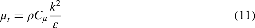
A standard k-ε two-equation model was used to solve turbulence flow in the thruster. Two-equation turbulence models allow the determination of turbulent length and time scale by solving two separate transport equations. The standard-model has become the primary tool of engineering flow calculations. Robustness, economy, and reasonable accuracy in a wide range of turbulent flows make it widely used in industrial flow and heat transfer simulations. Standard k-ε model is a model based on transport equations for the turbulence kinetic energy (k) and its dissipation rate (ε), which could be obtained from the following transport equations:

Species transport model with eddy-dissipation turbulence-chemistry interaction method was used to simulate chemistry reactions. Some related settings for simulation are shown in Table 2. Yi, which is the local mass fraction of each species i, and is predicted through the solution of a convection-diffusion equation, which takes the following general form:

Simulation settings.

Physical parameters of propellants that were used in numerical calculations of this work are listed in Table 3, for the convenience of calculation, the parameters were set as constant.
Physical parameters of propellants.

Model validation and grid independence analysis
Comparison of experiment and simulation results of combustion chamber pressure as a function of time is shown in Figure 5(a), as can be seen, simulation and experimental results of the variation of combustion chamber pressure over time are similar. The comparisons of simulation results and the thruster rated operating value of average combustion chamber pressure, thrust and specific impulse at 293 K are shown in Table 4. It can be seen that all the difference between simulation results and the rated operating values are less than 5%, indicating that the simulation model developed is reliable.

Model validation and grid independence analysis.
Comparison of simulation results and rated operating value.

Numerical errors were analyzed using grid independence estimate method. 22 In the same simulation conditions, the discretization errors of four different meshes with different global average sizes of grids were estimated. Total number of grids of the four meshes are 43,245, 77,837, 99,694, 122,900, respectively. The discretization error for combustion chamber pressure (εp) is plotted (in log-log scale) against global average grid size (h) in Figure 5(b), and its rate of decay can be visually assessed by comparison with the first- and second-order slopes.
As shown in Figure 5(b), the relative error asymptotically converges at a rate greater than 2nd order as the size of grids decreases. Considering relative error and computational resources, the mesh with total grid number 99,694 was selected for numerical simulation.
Results and discussions
Effects of oxidant type on characteristics of thruster starting process
As shown in Figure 5(a), combustion chamber pressure of the thruster rises significantly at a time of 6 ms, thus, working characteristics of the thruster starting process at a time of 3 ms were analyzed. Due to the fact that nozzle holes of propellants are all located on the same straight line, the flow field characteristics on the thruster section where nozzle holes are located (referred to as A-plane) are different from the section perpendicular to A-plane (referred to as B-plane). Therefore, in this article the characteristics on both sections will be discussed respectively.
MMH and oxidant liquids are injected into combustion chamber and broke up into droplets, droplets evaporate into gas phase oxidant and fuel, mixing and combustion occurred in the chamber, increase temperature and pressure, side path MMH contacts the wall of combustion chamber and then forms cooling liquid film, as shown in Figure 6. Due to high pressure in combustion chamber, gas mixture passes through Laval nozzle.

Cooling wall film of NTO/MMH and MON-25/MMH thruster in starting process.
Simulation results of temperature distribution in A-plane of NTO/MMH thruster and MON-25/MMH thruster are shown in Figure 7. During the thruster starting process, temperatures on A-plane of both NTO/MMH thruster and MON-25 thruster show higher temperatures near the axis, lower temperatures near the wall, and significantly lower temperatures at the cylindrical section wall compared to other positions. This is due to the fact that the cooling wall film has already coated the cylindrical section of combustion chamber during starting process, but has not reached the tapering section.

Temperature distribution in A-plane of NTO/MMH thruster and MON-25/MMH thruster starting process.
Distribution of main species in A-plane of NTO/MMH thruster and MON-25/MMH thruster in starting process are shown in Figure 8. The position with higher temperature basically coincides with the position with higher concentrations of H2O and CO, indicating that the main reactions that rise combustion chamber temperature during starting process are the oxidation of CH3 to H2O by NO, as well as small molecule oxidation-reduction reactions such as CO generated by HCN and OH.
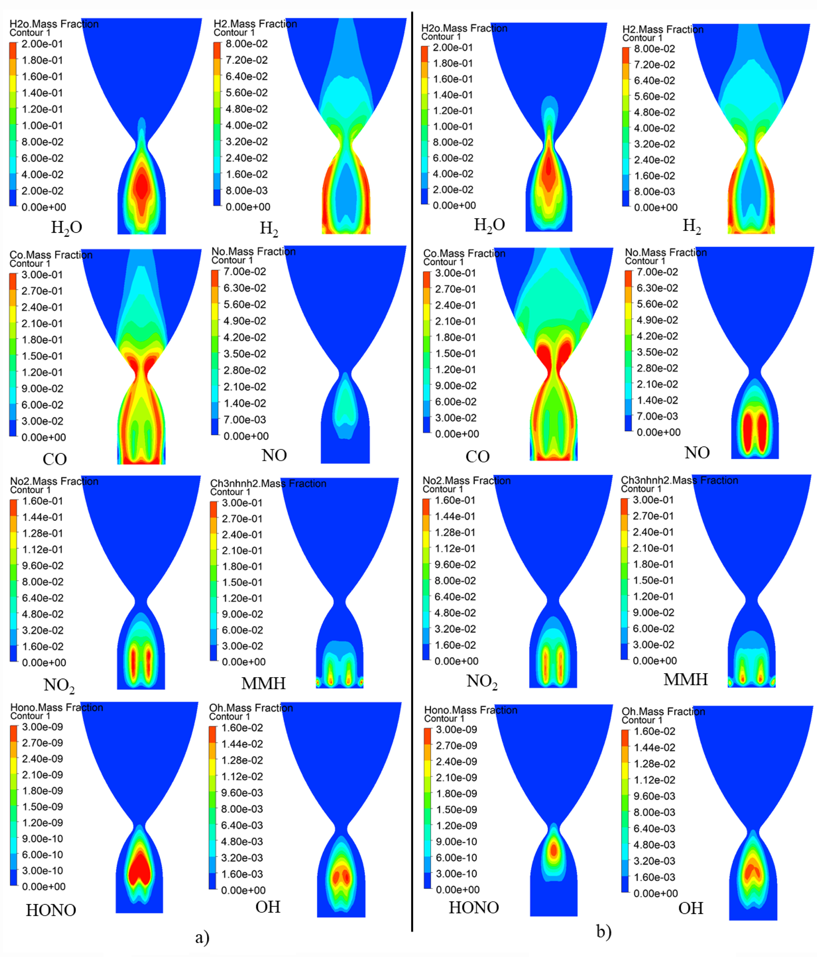
Distribution of main species on A-plane of NTO/MMH and MON-25/MMH thruster in starting process.
H2 is mainly distributed near the wall of A-plane, which is generated by the decomposition of MMH after gasification in the cooling liquid film on the wall. H2 concentration is higher near the wall, and its distribution in space near the axis is not significantly lower than that near the wall, indicating that, different from that in premixed reactor conditions, the self-decomposition of MMH has a greater effect on the dehydrogenation of MMH than the extraction of hydrogen atom from MMH by NO2 during starting process in actual combustion chamber conditions.
In addition, NO in A-plane of the NTO/MMH thruster is mainly distributed near the axis of combustion chamber, while NO in MON-25 thruster is mainly distributed at the position of propellant injection. This is obviously due to the existence of NO in MON-25 oxidant. The direct result of high NO content is that, MON-25 oxidant has lower content of N2O4, the reaction rate of R2-R4 in MON-25 thruster is slower than that in NTO thruster, therefore MON-25 thruster has less HONO than NTO thruster, subsequent reaction of CH3 generating and oxidizing are slower. Therefore, in the front end of A-plane, the NTO thruster has more H2O and CO distribution and higher temperature than those in the MON-25/MMH thruster. The lower temperature near the upper end of MON-25 thruster indicates MON-25 oxidant has advantage in reducing the thermal load than NTO oxidant.
Temperature distribution in B-plane of NTO/MMH thruster and MON-25/MMH thruster in starting process are shown in Figure 9. During starting process, temperature distributions on B-plane of MON-25 thruster and NTO/MMH thruster are similar. However, in tapering section of NTO/MMH thruster, temperature near the wall is higher than other locations, temperature distribution of MON-25 thrusters is more uniform than NTO thruster.

Temperature distribution in B-plane of NTO/MMH thruster and MON-25/MMH thruster.
As shown in Figure 10, the position with higher temperature in B-plane of combustion chamber also basically coincides with the position with higher concentration of H2O and CO. NO2, MMH and H2 are mainly distributed near the axis of B-plane, which is produced by gasification and decomposition of propellants in impinging spray. The obvious difference is that, during starting process, H2O in B-plane of NTO thruster is concentrated near the axis, and NO mass fraction in B-plane of NTO thruster is small, while H2O distribution in B-plane of MON-25 thruster is more uniform, and NO mass fraction in B-plane of MON-25 thruster is large. Obviously, this is due to the existence of NO in MON-25 oxidant, and NO in MON-25 reacts with CH3 and generates H2O, which is also the cause to the uniform temperature distribution in B-plane of MON-25 thruster.

Distribution of main species on B-plane of NTO/MMH and MON-25/MMH thruster in starting process.
Effects of oxidant type and initial temperature on thruster working characteristics and performance parameters
When the NTO/MMH thruster and the MON-25/MMH thruster are in stable working state, the distributions of thruster pressure, Mach number, and wall liquid film thickness are shown in Figures 11 and 12. It can be found that the pressure and Mach number distribution of thrusters using two oxidants are basically the same. Liquid film thickness and distribution range of NTO thruster are slightly larger than those of MON-25 thruster, which is because that, the temperature near the wall at B-plane in MON-25 thruster is higher than that of NTO thruster (as can be seen in Figure 17), more MMH in the liquid film of MON-25 thruster is gasified due to the higher wall temperature, results in a thinner and range-smaller liquid film.

Distribution of pressure and Mach number of NTO/MMH and MON-25/MMH thruster in stable working state.

Distribution of cooling film thickness of NTO/MMH and MON-25/MMH thruster in stable working state.
As can be seen in Figure 13, when the thruster is in stable working state, there are two continuous high-temperature regions between the axis and the wall in A-plane of NTO/MMH thruster, while the high-temperature regions of MON-25 thruster are discontinuous in the middle and lower part in the cylindrical section of combustion chamber.

Temperature distribution in A-plane of NTO/MMH thruster and MON-25/MMH thruster in stable working state.
The temperatures of both two thrusters are low at the wall of A-plane. Comparing the point-and-figure chart of temperature in Figure 13, it can be seen that the temperature near the wall at A-plane in MON-25 thruster is lower than that in NTO thruster, which indicates MON-25 oxidant has advantage in reducing the thermal load on the wall near A-plane of the thruster than NTO oxidant.
Distributions of H2O, CO, N2 in A-plane of NTO/MMH and MON-25/MMH thruster in stable working state are shown in Figure 14. As can be seen, distributions of CO and N2 in A-plane of the MON-25 thruster is basically the same as those of the NTO thruster. However, compared to NTO thruster, the distribution of H2O in MON-25 thruster is less in the middle and lower parts of the cylindrical section of combustion chamber, indicating that the reaction rate of R14 which generates H2O and HCN is slower at this location, which is also the main cause for the lower temperature at the same location shown in Figure 13.

Distribution of H2O, CO, N2 in A-plane of NTO/MMH and MON-25/MMH thruster in stable working state.
Distributions of H2, NO, NO2 in A-plane of NTO/MMH and MON-25/MMH thruster in stable working state are shown in Figure 15. The distributions of H2 in A-plane of the two types of thrusters are basically the same. The difference is that, the NTO thruster has less NO than MON-25 thruster in the combustion chamber cylindrical section, and has more NO2 than MON-25 thruster in the combustion chamber tapering section. A large amount of NO is in the MON-25 oxidant, which can be released immediately after the evaporation of oxidant, due to this reason, MON-25 thruster has more NO than NTO thruster in the combustion chamber cylindrical section.

Distribution of H2, NO, NO2 in A-plane of NTO/MMH and MON-25/MMH thruster in stable working state.
On the other hand, MON-25 has less N2O4 than NTO, N2O4 in MON-25 thruster will be consumed quickly by H extracting reactions, which caused the minor amount of NO2 in the combustion chamber tapering section of MON-25 thruster. While the consumed ratio of NO2 in NTO thruster is relatively small, so there is still NO2 in the combustion chamber tapering section of NTO thruster.
Distributions of HONO in A-plane of NTO/MMH and MON-25/MMH thruster in stable working state are shown in Figure 16. Comparing the mass fraction of HONO in Figures 8 and 16, it can be observed that, the mass fractions of HONO on A-plane in stable working state of both thrusters are significantly higher than that in starting process, indicating reactions that NO2 extraction H atoms in MMH have much higher activities in stable working state than those in starting process. In MON-25/MMH thruster, mass fraction of HONO is smaller at the top of combustion chamber than that in NTO/MMH thruster.

Distribution of HONO in A-plane of NTO/MMH and MON-25/MMH thruster in stable working state.
Mass fraction of HONO in MON-25 thruster is higher than that in NTO thruster from the middle to the lower part of the tapering section. This is due to the existence of NO in MON-25, which leads to a decrease in mass fraction of N2O4 in oxidant and a decrease in the product rate of NO2. The reaction rate of NO2 extracts H atom from MMH and its dehydrogenation products decreases, thus the generation rate of CH3 decreases. This leads to a delay in the generation of H2O and the heat release from this reaction, resulting in a decrease in temperature in the middle part of cylindrical section of the MON-25 thruster combustion chamber.
According to the above analysis and analysis in section Ⅲ A, during starting process, NO mainly has effects on temperature and species distribution at the upper part of combustion chamber, while in stable working process, NO mainly has effects on temperature and species distribution at the middle part of combustion chamber.
Distributions of temperature and main species in B-plane of NTO/MMH and MON-25/MMH thruster in stable working state are shown in Figures 17 and 18. Comparing the mass fraction of HONO in Figures 10 and 18, it can be observed that, the mass fractions of HONO on A-plane in stable working state of both thrusters are significantly higher than that in starting process. Main difference in temperature distribution between NTO/MMH thruster and MON-25/MMH thruster in B-plane is that, temperature distribution in B-plane of the NTO thruster is relatively uniform, and the wall temperature is not particularly higher compared to other positions, while temperature at the wall of MON-25 thruster is significantly higher than those at other positions, especially in the cylindrical section of combustion chamber.

Temperature distribution in B-plane of NTO/MMH thruster and MON-25/MMH thruster stable working state.

Distribution of main species in B-plane of NTO/MMH and MON-25/MMH thruster in stable working state.
The cause for the above phenomenon is that, MON-25 oxidant releases NO earlier than NTO and oxidize NH to N2, resulting in larger heat releasing near the wall. The species distributions of the MON-25 thruster on B-plane are more uniform than those of the NTO thruster, due to the existence of NO, which makes its distribution more uniform and has reactions with CH3, providing materials for subsequent reactions.
Considering the requirements of deep space exploration, study about thruster performance under different initial temperatures is highly important. Defining initial temperature, including environment temperature and propellant initial temperature, as T0, working characteristics of thrusters with different T0 and different oxidant types are shown in Figure 19. As gas mixture passes through the nozzle throat, the temperature and pressure drop rapidly, while velocity and Mach number rise rapidly.

Working characteristics of thrusters with different T0 and different oxidant type. (a) Pressure. (b) Velocity. (c) Mach number.
Performance parameters of thrusters with different T0 and different oxidant types are shown in Table 5. Combustion chamber pressure of MON-25/MMH thruster does not change evidently in initial temperature range 293 K to 263 K. When the initial temperature drops to 243 K, sudden decreases occur to average pressure of combustion chamber, thrust, and specific impulse. Axial variations of velocity and Mach number with different T0 and oxidant types are similar.
Performance parameters of thrusters with different T0 and different oxidant type.

The cause for the above phenomenon is that, gasification process of propellants is affected by the initial temperature. When the initial temperature drops from 263 K to 243 K, it passes through a critical value of propellant gasification. When initial temperature is lower than the critical temperature, gasification rate of propellants drops sharply, ultimately causing a decrease in the amount of gas in the combustion chamber, thereby reducing the pressure, gas velocity, and Mach number decrease due to decrease of pressure. When the initial temperature drops to 243 K, the gas density in the combustion chamber significantly decreases compared to that in higher initial temperatures, which confirms the above viewpoint.
In addition, the side-path cooling jet sprayed to the combustion chamber wall to form a cooling liquid film. When the initial temperature drops from 263 K to 243 K, the average thickness of the cooling liquid film increases sharply, which is also due to the affection of low temperature on gasification of propellants. As can be seen in Table 5, apparently MON-25 thruster has higher specific impulse than NTO thruster at the same T0, which generally indicates that MON-25 thruster has better performance than NTO thruster.
Conclusion
In order to study the operation characteristics of NTO/MMH and MON-25/MMH bipropellant liquid space thruster with impinging injection and investigate the influence of initial temperature on performances of the thruster, a three-dimensional simulation model was developed for a 25 N thruster, and the operation of thruster was numerically simulated at different oxidant types and different initial temperatures. The discussion of some phenomenon is as follows:
During the thruster starting process, A-plane temperatures of both NTO and MON-25 thrusters show high temperature near the axis; and lower temperature near the wall. The main reactions that affect temperature rise of combustion chamber during the starting process are the oxidation of CH3 to H2O by NO, as well as small molecule oxidation-reduction reactions such as CO generated by HCN and OH. During the thruster starting process in actual combustion chamber conditions, self-decomposition of MMH has a greater effect on the dehydrogenation of MMH than the extraction of hydrogen atoms from MMH by NO2.
The positions with high temperature in combustion chamber coincide with positions that have high concentration of H2O and CO. During starting process of NTO thruster, the concentration of H2O and NO in B-plane is relatively concentrated near the wall of tapering section, while distribution of the two is relatively uniform in MON-25 thruster. This is due to NO in the MON-25 propellant, which generates H2O with CH3. This is also the cause for the high temperature near the wall of tapering section of NTO thruster, while the temperature in MON-25 thruster is more uniform.
When the thruster is in stable operating state, there are two continuous high-temperature regions between the axis and the wall of NTO thruster, while the smaller mass fraction of N2O4 in MON-25 leads to a lower temperature in the middle of cylindrical section of MON-25 thruster. The temperatures of both two thrusters are very low at the wall of A-plane, which is because the cooling film has coated the tapering section of A-plane.
The discontinuity of high temperature region of MON-25 thruster is the main cause of the lower combustion chamber temperature than that of NTO thruster. Analysis shows that, high-temperature area at the top of the combustion chamber of MON-25 thruster is formed by heat releasing reaction that CH3 is oxidized by NO in the MON-25 oxidant to H2O and HCN. However, due to the decrease in mass fraction of N2O4 in oxidant, NO2 releasing is later in MON-25 thruster than that in NTO thruster, resulting in a delay of heat releasing reactions, which is the cause for discontinuity of high-temperature region in MON-25 thruster.
The mass fractions of HONO in NTO thruster and MON-25 thruster in stable working state are significantly higher than that in starting process, indicating that NO2 has a higher activity in the H extraction reaction with MMH during stable working state.
Combustion chamber pressure of MON-25/MMH thruster does not change significantly in the initial temperature range from 293 K to 263 K. When the initial temperature drops to 243 K, sudden drops occur to the combustion chamber pressure, thrust, and thruster specific impulse. The cause for the above phenomenon is that, the gasification process of propellants is affected by the initial temperature. When the initial temperature is lower than a critical temperature, the gasification rates of propellants suddenly decreases, ultimately resulting in a decrease in the amount of gas in the combustion chamber, thereby reducing the pressure, thrust, and specific impulse.
Summary
During starting and stable operating processes, dominant reactions of MMH dehydrogenation are self-decomposition of MMH and extraction of H from MMH by NO2, respectively. The main reactions that affect temperature rise of combustion chamber are OH oxidizes CH3 to H2O, and other small molecule oxidation-reduction reactions such as CO generated by HCN and OH. In stable operating state, the smaller mass fraction of N2O4 in MON-25 leads to a lower combustion chamber temperature in MON-25 thruster than that in NTO thruster. When the initial temperature of MON-25 thruster is 243 K and lower, severe lost on working performance of thruster occurred due to the impact of temperature on propellant gasification. MON-25 thruster has better performance in thrust and specific impulse, as well as more advantage in reducing the thermal load than NTO thruster.
Highlights
A three-dimensional simulation model was used to simulate the operation of thruster, combustion in the whole field of thruster was analyzed. Differences between working characteristics of NTO/MMH thruster and MON-25/MMH thruster were studied. Influences of low temperature on performances of thruster were studied and the cause for that was analyzed. The reactions that play major roles in temperature rise and dehydrogenation of methyl hydrazine were pointed out, in starting process and stable working state respectively. The cooling liquid film on the combustion chamber wall was simulated.
Footnotes
Abbreviations
Author contributions
The contributions of the authors are as follows: YU-HAO ZHOU: modeling; performing simulation and analyzing data. RONG-PEI JIANG: provides guidance for modeling and provides geometrical parameter of the thruster. GUO-XIU LI: provides computing devices. HONG-MENG LI: provides guidance for simulation and writing of paper. TAO FANG: provides guidance for data analyzing. KUN TONG: provides experimental data to validate the model. The individuals who admire you, YU-HAO ZHOU, RONG-PEI JIANG, GUO-XIU LI, and HONG-MENG LI, together with TAO FANG and KUN TONG.
Declaration of conflicting interests
The authors declared no potential conflicts of interest with respect to the research, authorship, and/or publication of this article.
Funding
The authors disclosed receipt of the following financial support for the research, authorship, and/or publication of this article: This study has been supported by the Fundamental Research Funds for the Central Universities (No. 2022JBZY033) and the National Natural Science Foundation of China (No. 52176097).