
Abstract
This article reveals the chip formation and the reducing of cutting force mechanisms of nickel-based superalloy Inconel 718 under elliptical vibration cutting using finite element analysis software. The results are compared with traditional cutting methods. The elliptical motion trajectory of the tool in elliptical vibration cutting machining is analyzed, and a two-dimensional finite element elliptical vibration cutting model is established. The effects of dynamic impact on the elliptical vibration cutting of Inconel 718 were discussed in terms of the surface morphology, chip formation mechanism, and cutting force reduced mechanism. The simulation results show that (1) compared with traditional cutting, the surface morphology of the workpiece machined by elliptical vibration cutting is better, and the machined surface has obvious elliptic indentation; (2) in traditional cutting, sawtooth chips are formed through shear slip, while in elliptical vibration cutting, the faster relative cutting speed
Introduction
Nickel-based high-temperature alloy Inconel 718 is known for its excellent physical and chemical properties. Compared with other metals, Inconel 718 maintains its strength and corrosion resistance better at temperatures higher than 700 °C. Therefore, Inconel 718 is widely used in the high-temperature working parts of aviation and aerospace gas engines. However, due to the low thermal conductivity, high work-hardening, and high chemical affinity characteristics of this alloy during machining, the machining is prone to high temperatures, high cutting forces, and adherence to the tool, resulting in difficulty in ensuring the quality of the machined surface, and causing serious tool wear, thus the machinability of this alloy is relatively poor, and it is regarded as a typical difficult-to-machine material.1–3 The chemical composition and mechanical properties of Inconel 718 are shown in Tables 1 and 2, 4 respectively. Machined surface integrity is critical to the service life and service performance of nickel-based high-temperature alloy components in aerospace and other fields. Surface integrity is closely related to chip morphology, cutting temperature, and cutting force during machining. For this reason, chip morphology and its fracture mode have received intensive attention in the field of machining. Zhang et al. 5 found that when the free surface of the chip has a typical serrated morphology, folds can be observed on the back of the chip, and the mechanism is attributed to the formation of serrated chips due to the large strain caused by high-speed cutting. In addition, the strong sliding behavior between the backside of the chip and the tool caused the debris of the ceramic tool to adhere to the chip, resulting in adhesive wear of the tool. A study by Ming et al. 6 found that the clogging of chips leads to severe scratching and change in the color of the hole surface, which also contributes to the occurrence of defects on the surface of the hole and nanocrystalline microstructure transformation. Therefore, chip morphology has a significant impact on the integrity of the drilled hole surface. In order to obtain a better-machined surface quality, it is necessary to thoroughly investigate the chip formation mechanism and its evolution during the machining of nickel-based superalloys.
Chemical composition of Inconel 718 alloy (wt.%).

Mechanical properties of Inconel 718 alloy.

Elliptical vibration cutting (EVC)
Finite element analysis (FEA) has been reported extensively in cutting technology research. Compared with the experimental study, the FEA method is economic. 16 In the FEA of UEVC cutting Inconel 718 machining, it was found that ultrasonic vibration resulted in an increase of the shear angle in the cutting region, leading to a lower chip thickness than conventional turning. 17 Additionally, Babitsky et al. 18 found that more regular chips were produced in ultrasonic vibration-assisted turning and the chips produced in conventional turning had distinctive shear bands using electron scanning microscopy, and the equivalent plastic strain in the cutting region was simulated using FEA. However, the reasons for the formation of more continuous chips in ultrasonic vibration-assisted turning and the formation of chips with distinct shear bands in conventional turning, as well as their evolutionary processes, which should be further investigated. In the simulation of UEVC cutting TiC-particle reinforced titanium matrix composites machining, compared with traditional cutting (TC), it was found that the cutting speed became larger and the cutting force became smaller at the instant of the tip contacting the substrate, which in turn caused the material deformation to be small, reduced the machined surface roughness, and formed a better-machined surface. 19 The above studies show that, as an economic method, FEA has been widely used in the simulation research of machining, and is beneficial in presenting the dynamic evolution of chips and machined surfaces during machining.
Therefore, EVC technology has better machining performance than TC. In order to expand the application of EVC technology in the field of nickel-based high-temperature alloy machining, this article investigated the chip formation mechanism and cutting force reduction mechanism of Inconel 718 under EVC machining, established a two-dimensional (2D) EVC finite-element model of Inconel 718 by using ABAQUS software and conducted simulation to the deformation behavior of the cutting layer and the dynamic evolution of the chip process of Inconel 718 under EVC machining. The effects of the intermittent cutting behavior of the tool and the cyclic dynamic impact of elliptical vibration on the machined surface morphology, contact zone stress, cutting force, and tip temperature were comparatively investigated.
Kinematics analysis of EVC
Elliptical vibrational motion is a synthesis of two simple harmonic motions in the plane of the same frequency, in directions perpendicular to each other and with a certain phase difference,
20
assuming that the equations of motion in both directions are


Schematic diagram of the principle of a single elliptical vibration trajectory.
The first stage is an a-b stage, which has the maximum removal efficiency in this stage. The second stage is the b-c stage, in which the front tool face reverses the chip direction, which can effectively inhibit the germination of chip tumors, thus improving the tool life and forming better processing quality. 22 The third stage is the c-d stage, in which the tool is not in contact with the workpiece and the tool begins to cold cut.
Finite element simulation
Finite element simulation is a set of mathematical linear equations that transforms an infinite degree-of-freedom problem in the continuous domain into a finite-degree-of-freedom problem to be solved in the discrete domain and is suitable for the study of complex physical phenomena in machining processes, such as the simulation of stress and temperature fields. The contact process between the tool and the workpiece during the machining presents material and geometric nonlinearities. ABAQUS simulation software is powerful in processing and simulating complex nonlinear problems in the machining process, so ABAQUS/Explicit was used to simulate EVC cutting of Inconel 718.
Establishment of 2D model
The workpiece length is 5 mm and the height is 2.5 mm. The simplified model is shown in Figure 2. Due to the simulation process is a 2D EVC cutting Inconel 718 thermodynamic coupled processing, planar quadrilateral continuous elements (CPE4RT) 23 was used for the workpiece mesh, and the mesh element removal technology was used to realize the separation of chip and workpiece. In order to eliminate tool deformation and wear during EVC cutting, the tool is set to a rigid body to facilitate better analysis of the workpiece chip evolution mechanism during machining. The reference point RP was set on the upper right of the tool and the cutting speed to the reference point RP was set as 400 mm/s. In the simulation, the tool vibration frequency is 5000 Hz, and the amplitude is A = 0.3 mm, B = 0.25 mm. In order to improve the simulation efficiency, the height of the undeformed layer was set to 0.6 mm and refined. The refined cell mesh size is 0.025 mm × 0.025 mm, and the matrix part of the material model is 0.225 mm × 0.025 mm. In addition, constraints are applied at the bottom of the workpiece to ensure that the workpiece is fixed, and the predefined field temperature of the EVC cutting model is set to 20 °C. According to the existing research results, 24 CBN tools have obvious advantages in processing nickel-based superalloys, such as high thermal conductivity, endurance, and good compressive strength, so CBN tools are selected in this article. The rake angle and the clearance angle of the CBN tool are 0° and 15°, respectively, and the radius of the tool tip is 0.05 mm.

Finite element model in elliptical vibration cutting (EVC).
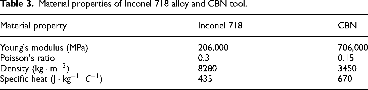
The material properties of workpieces and tools are shown in Table 3. 25
Material properties of Inconel 718 alloy and CBN tool.
Determination of material parameters
Material constitutive equation
In the simulation process, the constitutive equation of the workpiece material plays a crucial role in capturing the relationship between material flow equivalent stress, equivalent stress, equivalent strain rate, and temperature. The J-C (Johnson-Cook) model is commonly employed to represent this constitutive relationship. The J-C model incorporates three essential effects: strain hardening, strain rate hardening, and thermal softening. It is particularly suitable for describing the stress-strain behavior of metal materials under high strain rate conditions. The expression of the J-C model is as follows:
26
 (5)
where
(5)
where
Chip separation criteria
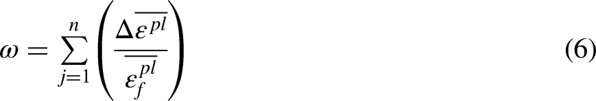
The chip separation criterion can be categorized into two types: the physical separation criterion and the geometric separation criterion. In this study, the physical separation criterion is adopted, which means that the chip is generated when a specific physical quantity reaches a predetermined threshold value. To simulate the damage of metal materials accurately, the J-C damage evolution model is employed. In this model, when the damage parameter exceeds 1, the material is considered to have failed. The expression of the J-C damage evolution model is as follows:
27
 (7)
(7)
Coefficients for Johnson-Cook (J-C) stress flow model of Inconel 718.

where p is the compressive stress, q is the equivalent stress,
In ABAQUS simulation, the damage evolution of metal chip separation can be characterized using both energy separation and displacement separation criteria. In this study, the displacement separation rule is selected as the criterion for chip separation. The expression for the displacement separation criterion is as follows:
Johnson-Cook (J-C) shear failure parameters of Inconel 718.

Friction model
During the cutting process, the contact area between the tool and the workpiece gives rise to two types of friction regions: the adhesive region and the slip region. These friction regions are characterized using a modified Coulomb friction model in the simulation. The expression for the modified Coulomb friction model is as follows
29
:
Simulation results and analysis
Surface topography
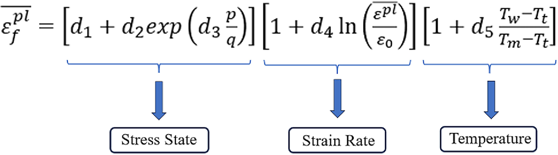
Figure 3 shows the stress contour plot of the machined surface, along with a magnified view of a specific region, both with and without EVC. Figure 3(a) is the surface machined by EVC, and Figure 3(b) is the surface machined by TC. It can be seen from Figure 3 that under EVC machining, the path of the tool on the workpiece surface is an elliptical path, and the cutting depth
Comparison of surface morphology in the cutting process: (a) EVC; and (b) TC.
In addition, in TC machining, unexpected features, such as burrs and small defects, are observed on the machined surface, which is absolutely not allowed for the surface requirements of precision parts. Therefore, as mentioned above, the excellent surface quality obtained by EVC processing is further confirmed.
Traditional cutting force and chip formation process
Figure 4 is the variation of cutting force in TC with a depth of cut of 0.5 mm and a cutting speed is 24 m/min. As machining proceeds, the workpiece comes into contact with the tool. Under the extrusion of the tool, the material undergoes plastic deformation, and the value of the NCF (normal cutting force) increases dramatically, reaching a maximum value of about 380 N. Then, the cutting depth remains unchanged, the cutting enters a stable state, and the NCF decreases to a certain extent, and in this stage, the NCF value shows periodic changes, fluctuating around 200 N. When the tool leaves the surface of the workpiece, the contact surface of the extrusion is changed from the front face of the tool to the rear face, and the extrusion effect of the tool on the workpiece is weakened, and as a result, NCF decreases. When the tool completely leaves the surface of the workpiece, there is no extrusion between the tool and the workpiece, and the NCF decreases rapidly to 0, as shown in Figure 4(a).
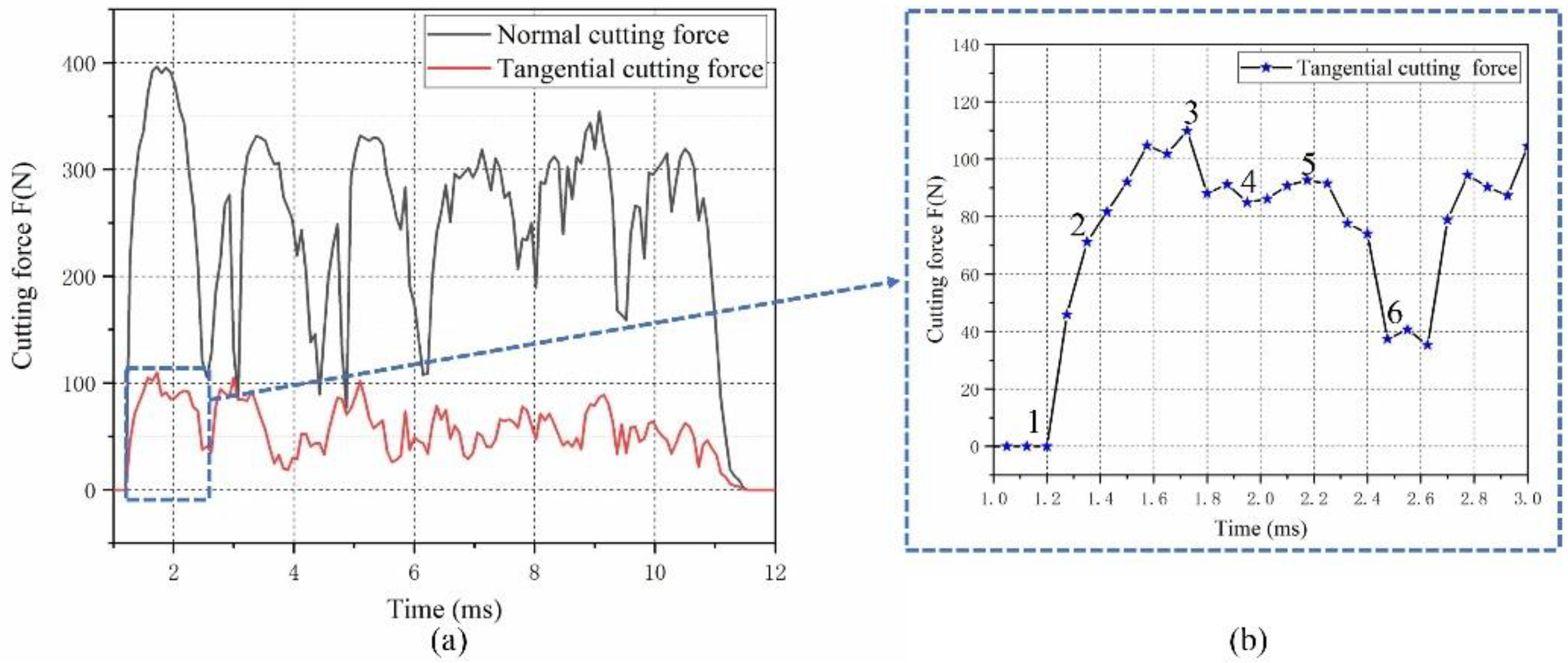
The force diagram in traditional cutting (TC): (a) normal force and tangential force; and (b) magnification of local tangential forces.
In a machining process, sawtooth chips are composed of multiple units of sawtooth chips after many single-toothed chips undergo adiabatic shear slip behavior. The evolution law of a single sawtooth chip is closely related to the change of cutting force. However, in the actual cutting process, the formation process of the chip is very fast, which is not easy to observe. In order to further reveal the evolution of a single sawtooth chip, a contrast analysis is conducted by employing the TCF (tangential cutting force) change curve (Figure 4(b)) and the simulated sawtooth chip cloud pictures (Figure 5).
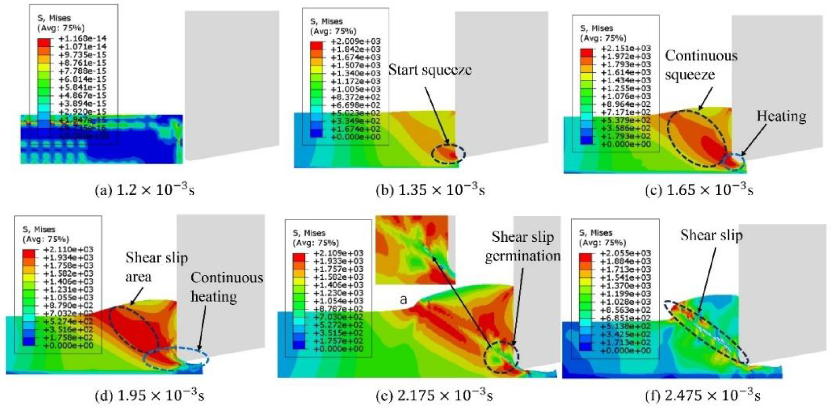
The formation process of single sawtooth debris: (a) 1.2 × 10⁻³ s; (b) 1.35 × 10⁻³ s; (c) 1.65 × 10⁻³ s; (d) 1.95 × 10⁻³ s; (e) 2.175 × 10⁻³ s; and (f) 2.475 × 10⁻³ s.
At the very beginning of contact between the tool and the workpiece, under the action of the impact load of the tool, the tool and the workpiece begin to extrude, and the material undergoes plastic deformation, as shown in (b) of Figure 5, resulting in a sharp increase in the TCF, which reaches about 73 N, point 2 in Figure 4(b), at which the value of the stress can be seen as

Schematic diagram of the principle of sawtooth debris: (a) serrated chip schematic; and (b) schematic of a simulated sawtooth chip.
Through the above analysis, it can be found that the periodic change of cutting force value and the formation of sawtooth chips can be well corresponding. The cutting force value increases rapidly when the workpiece is initially squeezed by the tool. When the softening effect and strain strengthening effect reach a certain balance, the adiabatic shear slip condition is formed, 30 then the shear slip is produced, and the cutting force value decreases rapidly.
Influence of elliptic vibration on chip morphology
In EVC machining, the variation curves of NCF and TCF are shown in Figure 7, where the frequency is 5000 Hz and the amplitude is 0.25 mm.

The variation curves of NCF and TCF in the EVC: (a) Normal and tangential forces; (b) The partial enlarged curves of NCF and TCF.
Due to the evolution of chips in the machining process being rapid and not easy to be observed, the trends of NCF (Figure 7) and the simulation of chip morphology (Figure 8) were combined to analyze the evolutional process of chip morphology in a single EVC cycle. Figure 8(a), (c) and (e) correspond to points 1, 2, and 3 in the graph of Figure 7(b), respectively.

The evolutional process of a chip in a single elliptical vibration cutting (EVC) cycle: (a) 1.2 × 10⁻³ s; (b) 1.25 × 10⁻³ s; (c) 1.3 × 10⁻³ s; (d) 1.35 × 10⁻³ s; and (e) 1.4 × 10⁻³ s.
When the tool is not in contact with the workpiece, there is no squeezing action and the cutting force is 0 N, namely, point 1 in the diagram of Figures 7(b) and 8(a). At the beginning of EVC machining, the tool enters the material removal stage, corresponding to stages (a) to (c) in Figure 8. When the tip of the tool comes in contact with the workpiece, with the squeezing action of the tool, the contact zone undergoes plastic deformation. From Figure 8(a) to (c), it can be seen that the stress value increases from
There are three reasons for producing this type of chip: firstly, in EVC, the cutting speed

Tool travel path diagram.

Temperature cloud map during material removal phase in elliptical vibration cutting (EVC): (a) 1.85 × 10⁻³ s; and (b) 1.9 × 10⁻³ s.
Secondly, in the cutting process, the heat generated is carried away by chips, workpieces, tools and coolants. Since the coolant factor is not considered in the simulation cutting process, the dispersion of cutting heat can be illustrated in Figure 11, where Qt1 and Qw1 are expressed as the heat into the CBN tool and the machined surface, respectively; Qc1 and Qw2 are expressed as the heat into the chip and the workpiece to be machined, respectively; and Qc2 and Qt2 are expressed as the heat into the chip and the workpiece, respectively; h1 and h2 are the chip thicknesses under the two machining methods.

Schematic diagram of heat dispersion: (a) EVC; (b) TC.
Finally, the material removal diagram of TC and EVC is shown in Figure 12(a) is the cross-section area of the material removed by a single elliptical cycle tool under EVC machining, representing the enlargement of the blue box in Figure 12(b), and the cutting depth
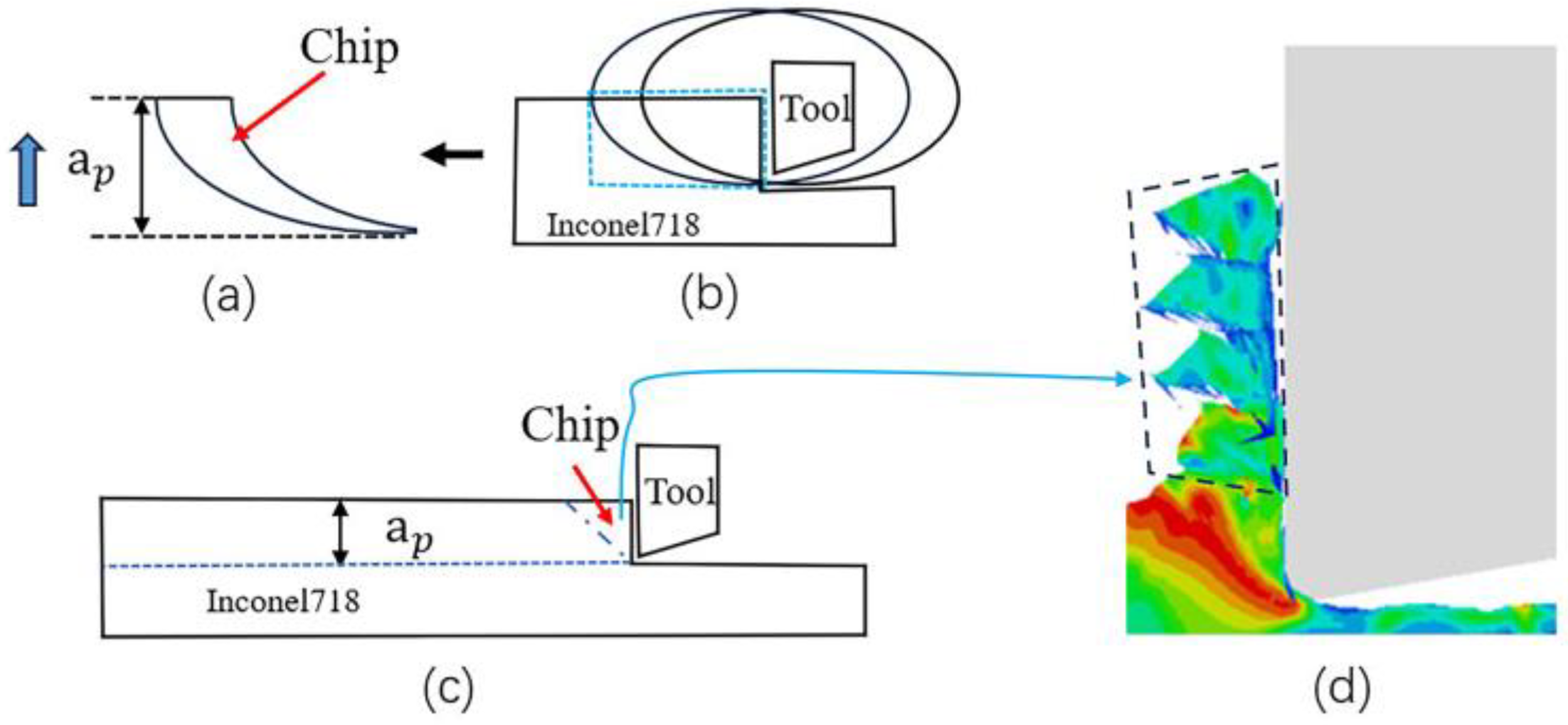
Chip formation: (a) and (b) EVC; and (c) and (d) TC.
According to the above analysis, under the same test parameters, the relative cutting speed

Plastic strain components at different stages: (a) 1.85 × 10⁻³ s; and (b) 1.9 × 10⁻³ s.

The rubbing-ploughing-chip formation schematic in elliptical vibration cutting (EVC).
Reducing mechanism of cutting force under elliptical vibration
Due to the simple harmonic characteristics of EVC, it is evident, from Figure 7(a), that the cutting force curves of EVC present periodic changes. Under EVC, the average NCF is 124.5 N and the average TCF is 22.7 N. As shown in Figure 4, the average NCF and TCF of TC are 256.1 and 57.9 N, respectively. Compared with TC, the average NCF of EVC is reduced by proximately 51.4% and the average TCF is reduced by about 60.8%.
Compared with TC machining, the reduction mechanism of cutting force in EVC is explained from the following three aspects: firstly, in EVC, the depth of cut

Schematic diagram of material removal in elliptical vibration cutting (EVC).

Tool-tip temperature curve: (a) temperature curve in TC; and (b) temperature curve in EVC.
Conclusion
In this article, Inconel 718 machined by EVC method was simulated by using ABAQUS finite element software, and the chip formation and the reducing of cutting force mechanisms in the cutting process with or without EVC was analyzed, and the conclusions can be found by comparison and discussions:
Through comparative analysis, it is found that in EVC, the machined surface shows a higher overall finish without burrs and small defects, while in TC, burrs and small defects appear, which indicates that in EVC, the surface quality is higher than that of the machined surface in TC. In the case of TC, the chip evolution mechanism is the combination of strain hardening effect and heat softening effect to form an adiabatic shear slip region, and finally, shear slip occurs to form a sawtooth chip. In EVC, due to greater relative cutting speed Due to the machining characteristics of EVC, the average cutting force in EVC is lower than that in TC. On the conditions presented in this article, the average NCF is reduced from 256.1 to 124.5 N, a reduction of about 51.4%. The average TCF is reduced from 57.9 to 22.7 N, a reduction of about 60.8%.
In the future, the effect of thermal softening and strain hardening of ultrasonic vibration-assisted machining on the evolution of micro-structures of machined surfaces should be further investigated.
Footnotes
Declaration of conflicting interests
The author(s) declared no potential conflicts of interest with respect to the research, authorship, and/or publication of this article.
Funding
The author(s) disclosed receipt of the following financial support for the research, authorship, and/or publication of this article: This work was supported by the Key Laboratory Project of Guizhou Higher Education Institutions, Guizhou Provincial Basic Research Program (Natural Science), Guizhou Province Science and Technology Projects, Major Science and Technology Project in Guizhou Province (Grant Nos. Q.J.J[2023]009, QKHJC-ZK[2023]YB077, and Q.K.H.Z.D.Z.X.Z[2019]3016).
Author biographies
Guoshun Tong is a graduate student at Guizhou University, Guiyang, Guizhou, China. His research interest is ultrasonic vibration assisted machining.
Lv Yang is a Ph.D. associate professor at Guizhou University, Guiyang, Guizhou, China. His research interests include precision machining technology and tribology.
Bin Ji is a Ph.D. student at Guizhou University, Guiyang, Guizhou, China. His research interest is ultrasonic vibration assisted machining.
Huaichao Wu is a Ph.D. professor at Guizhou University, Guiyang, Guizhou, China. His research interests include precision grinding, tribology and surface engineering.
Fengyi Zou is a graduate student at Guizhou University, Guiyang, Guizhou, China. His research interest is ultrasonic vibration assisted machining.