
Abstract
The replacement of humans by machines has gradually become a technological trend. In this study, a dual robotic arm was used in the belt conveyor operation system to track the screw and nut assembly using mutual visual tracking and positioning technology. Moreover, this study simulated the automatic assembly process using a dual robotic arm in a smart factory. An inverse kinematics operation was constructed using a geometric method to control the dual robotic arm to track the screw and nut assembly on the conveyor belt in real time using mutual visual tracking and positioning technology based on a single-lens charge-coupled device of a robotic arm. This study utilized a dual robotic arm to grab the screw and nut using fuzzy visual tracking control. After completing the grabbing of the screw and nut with tracking and positioning errors of 8%, the dual robotic arms continued to complete the assembly of the screw and nut. Therefore, through the establishment technology of mutual visual tracking and positioning of the dual robotic arm in this study, assembly tasks can be efficiently completed in related fields in the future.
Keywords
Introduction
Today's society has entered the era of Industry 4.0, and technology has become more and more developed. In order to solve the crisis of aging society and rising labor costs, it is an inevitable result to develop machines to replace part of the labor force. Automated production is an important means of solving the lack of labor. In automated production, the work, from raw materials, assembly, and classification to packaging, is automatically controlled by the machines. Among these, automatic assembly is extremely important as it can significantly reduce the labor costs. It is an automated project with a high return on investment. Therefore, this study aims to develop an automatic assembly system. In automatic assemblies, the work1–3 of “locking the screws” is the most basic, and it is the part that many manufacturers ponder over. The methods used by different companies are different, and have their own advantages and disadvantages. Therefore, this study discusses a method for completing the work of “locking the screws” in an automatic assembly system. In the field of automatic machine assembly, the application of robotic arms is extensive. By imitating the function of the human arm,4–8 manual work or repetitive and time-consuming tasks cannot be performed by humans, to achieve automation instead of manpower. In research on automatic assembly, the most basic design is the assembly plan,9–11 which defines the assembly sequence, assembly path, part location, and assembly operation. The path of the assembly can determine the necessary degrees-of-freedom (DOF) of the assembly equipment. Subsequently, it is decided whether to design or update a device that is more suitable for completing the assembly task, in line with the standard of automatic assembly system evaluation. After completing the aforementioned design, the real system can be integrated. The settings in the machine control system are synchronized to the machine control system, the robot is controlled in the virtual environment,12–14 each operable component is controlled, and the pre-planned path is entered. Then, the error information is captured, including the collisions, when simulating the assembly task. The search-based system is then transmitted to plan a new path, avoiding the possible risks, and passed to the virtual system again to simulate the assembly task until an executable path is obtained. This simulation process can understand some possible processes that were not considered in the original path, so that the equipment of the real system can avoid physical problems, such as, damage during the assembly task. In addition, the system can be trained using a machine learning algorithm,15–17 based on supervised learning-type classification learning to predict the location information for high-precision automated assembly. Furthermore, although the automated assembly improves the product quality and reduces the assembly time, the cost of equipment increases significantly. Therefore, the design18–20 of the assembly sequence and ergonomics should be improved, and suitable workstations should be selected to create an automated assembly system. The efficiency is maximized to achieve the desired batch requirements.
Under the aforementioned conditions, owing to the various environmental factors and manual interventions, various automatic assembly systems have been developed in the modern society of Industry 4.0. The robot center 21 has replaced the conveyor belt and has achieved the goals of cost reduction, simple operation, and high product quality. The improvement in product quality also represents the stability of its technology, enabling it to achieve self-management, self-optimization, and self-development trends for a fully automatic assembly. Based on this, an assembly task 22 was carried out, and three robots with 6-DOF were controlled to assemble the sensors. Consequently, the maintenance reduced by 80%, and the occurrence rate of defective products was also reduced. Laser marking was performed at the top to achieve a complete automatic assembly process. There are also related results for high-precision automatic assemblies. 23 The assembly accuracy can reach micrometers. On the alignment parts, an orthogonal alignment adjustment mechanism based on microscopic machine vision is proposed, which can obtain images and matrices and perform adjustments on important factors, such as, fine-tuning platform, swing arm, system errors analysis, and vacuum adsorption of parts to the swing arm to achieve large-scale micro-automatic assembly technology. From home to industrial fields, the applications of robotic arms are extremely diverse. Therefore, the design, manufacture, and control of the robotic arm 24 consider many factors, from the shape and DOF of the robotic arm to the cost of the frame, difficulties in assembly, etc. When the robotic arm has more DOF, 25 the number of joints in the arm increases, which means that it can control multiple angles. Compared with a robotic arm with fewer DOF, it can perform more varied and finer operations with great potential. In addition, many studies26–28 have proposed the mechanism material, weight, and inertia of the related robotic arm to the effective power and torque, as well as the fabrication and design of the base. Combined with the control system and selection of appropriate power components and various circuit boards, as well as effective control methods, the optimal design and production of the robotic arm can be achieved. Most of the available robotic arms are single robotic arms with single charge-coupled device (CCD)29–31 or two CCDs32–34 for object tracking and positioning. Compared with double robotic arms, the operation is simpler and the work that is completed is less time than that with double robotic arms. Although dual robotic arms are difficult to control, they quickly perform many complex actions. However, based on fixed positions of the CCDs,35,36 dual robotic arms only complete the positioning and grasping of objects, but do not complete mutual tracking, positioning, and assembly. Therefore, dual robotic arms integrated two CCDs perform more relative motion and improve work efficiency. Hence, this study integrates two CCDs in the dual robotic arms to complete the establishment of an automatic assembly system with visual tracking and positioning technology. Finally, this study utilizes this system to complete the work of “locking of the screw.”
Apparatus for dual-robotic-arm system
The overall system of dual robotic arms in this study, such as Figure 1, includes 12 motors of the main body, and a single robotic arm has four-degree of freedom (4-DOF) to be responsible for the rotation of the joint, the change of direction, and the opening of the gripper. There is one for each of the combinations, the rotation tightening screw responsible for clamping the object, and a CCD (Pixy2) with a 1296 × 976 pixel image resolution for capturing images. In addition to the main body of the robot arm, the overall system of the dual robotic arms also includes a motor controller (CarDuino UNO) for motor control to perform clamping of the gripper and assembly of the screw rotation. Each CCD was connected to a CCD controller (Arduino MEGA2560) to capture the required information. Finally, we used a belt conveyor controller (Arduino UNO) to control the conveyor belt to move at the target speed and direction so that the dual robotic arms could visually track and grasp the screws and nuts on the conveyor belt. Finally, the assembly of the screws and nuts was completed.

Schematic of the dual-robotic-arm system.
For the design of the gripper, we adopted a three-jaw type with a relatively stable grasping state, which uses 3D printing technology for manufacturing, as shown in Figure 2. The rack and servo motor (MG90S) was used to drive the clamping and loosening of the jaws, while the MG 995 was designed to be installed behind the clamp to avoid the signal caused by the servo motor (MG995) rotating through the gear to lock the clamp and winding of the wire.
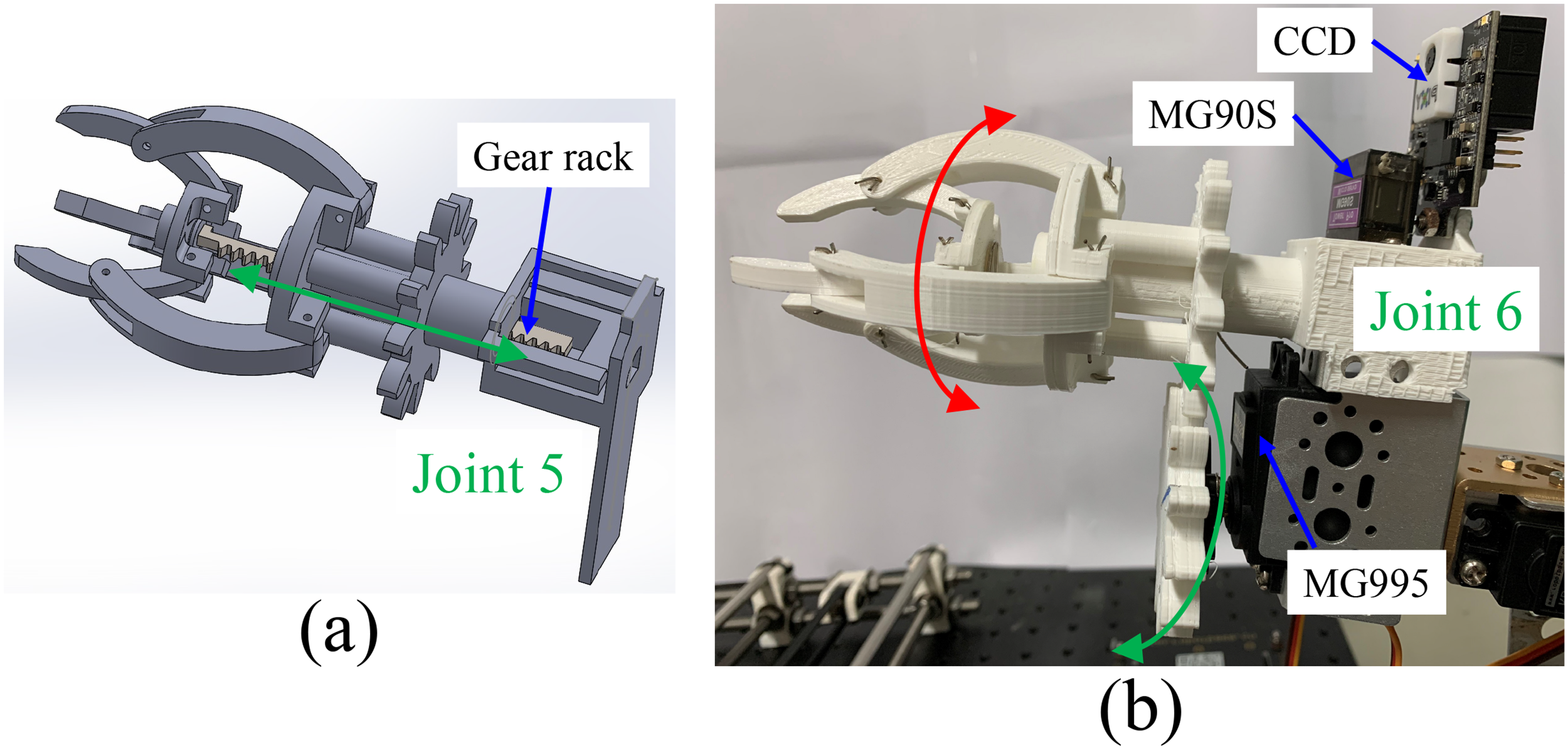
(a) Schematic of the gripper and (b) image of the gripper.
In this study, double robotic arms were used to perform the locking screw action, so the selection of the clamp was the screw and nut. To individually clamp the screws and nuts using the dual robotic arms, this study used 3D printing technology to print the screws and nuts and painted blue over the screws and yellow over the nuts. Finally, it was placed on the conveyor belt, and its relative dimensions and photos are shown in Figure 3.

Images of (a) screw, (b) nut, and (c) screw and nut on the belt conveyor.
Control design of dual robotic arm
When assembling, the relevant components will be placed on the conveyor belt, and the corresponding components will be clamped by visual tracking through the dual robotic arms, and then assembled. During this process, the components moved dynamically on the conveyor belt. Therefore, in this study, the CCD of the individual manipulator was used to move forward with the two-dimensional vision sensing (TVS) method
37
and the orientation tracker of the matched manipulator


Schematic of the TVS method.
The distance between the robot arm and the object is x, n and m are the FOV width pixels before and after the CCD moves

To grasp the assembled parts, we used fuzzy visual tracking control to accelerate and stabilize the assembly task. The control block diagram is shown in Figure 5.

Control block diagram of dual robotic arm for visual tracking and positioning.
Dynamic plant of dual robot arm
As shown in Figure 1, this study used fuzzy visual tracking control to control the angles (
The coordinates of the 4-DOF robot arm of a single robot arm are shown in Figure 6.

Coordinates of the right 4-DOF robot arm.
The relevant parameters are defined as:
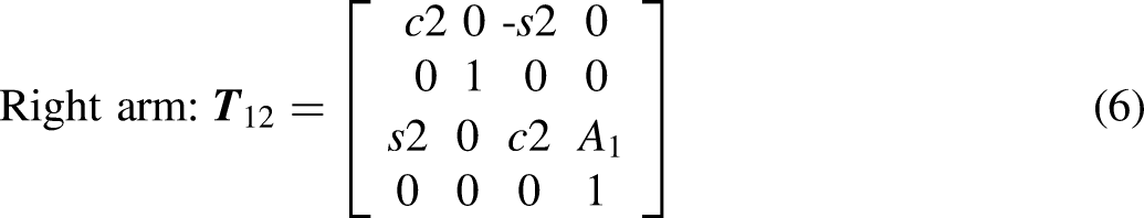
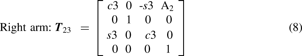
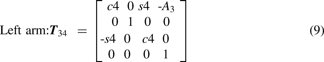
Before obtaining each angle through inverse kinematics, it is necessary to obtain the homogeneous transformation matrix of each axis, such as, Equations (3) to (12), to obtain


Because the left arm is rotated clockwise, R is the inverse of normal R.
Both the left and right arms moved

Because the left arm is rotated clockwise, R is the inverse of normal R.
Extend the left arm in the negative X-direction

Because the left arm is rotated clockwise, R is the inverse of normal R.
Extend the left arm in the negative X-direction

The left arm was extended in the negative X-direction
Both the left and right arms moved


After successively multiplying these matrices, the position of the effective gripping point of the gripper can be obtained and expressed as


The passed


Equations (15) to (16) show that in the Cartesian coordinate system, the inclination of the slope of a straight line on a known plane can be regarded as an arctangent function; thus, Equations (17) to (18) are obtained as:


Among them,
The x- and z-positions of the left and right arms are obtained from Equations (15) to (16), as expressed by Equations (19) to (20):


Then, the x- and z-positions of the left and right arms are pushed back from the CCD position to the fourth rotation axis using Equations (21) to (22) as:


The x- and z-positions of the fourth rotation axis of the left and right arms relative to the first rotation axis can be obtained, which are represented by α and β, as:

For

The included angle

According to Figure 6, because

Because the left arm rotates clockwise, based on Equation (28) , a minus sign must be added to
φ in Figure 6 can also be derived from the cosine theorem, as:
Because the left arm rotates clockwise, based on Equation (29) , a minus sign must be added to
The angle

Because the left arm
According to Figure 6,

Because the left arm
Angle

According to the bivariate arctangent function theorem, Equation (33) is obtained as:

Comparing Equations (15) to (16) with the homogeneous transformation matrix substituted into the total rotation angle of the arm, Equations (34) and (35) are obtained as:

According to Equations (34) and (35), we obtain


Substituting Equations (36) to (37) into Equation (33) , the total rotation angle of arm


Finally, according to Equations (28), (31), and (32),

Therefore, in this study, the position of the
Fuzzy visual tracking control
According to Figure 5, we used a CCD to capture images of screws and nuts, and obtain the center image coordinates of the object and the distance between the robot arm and the object using the TVS method as the input parameters of fuzzy visual tracking control. For example, Figure 7 shows that the CCD takes the upper left corner as the origin coordinate (0, 0) to capture the image and recognizes that the object center coordinate is (195, 140) pixels, and the distance from the object is 42 mm. Finally, the 4-DOF robot arm position control command was output through the fuzzy rule. 39
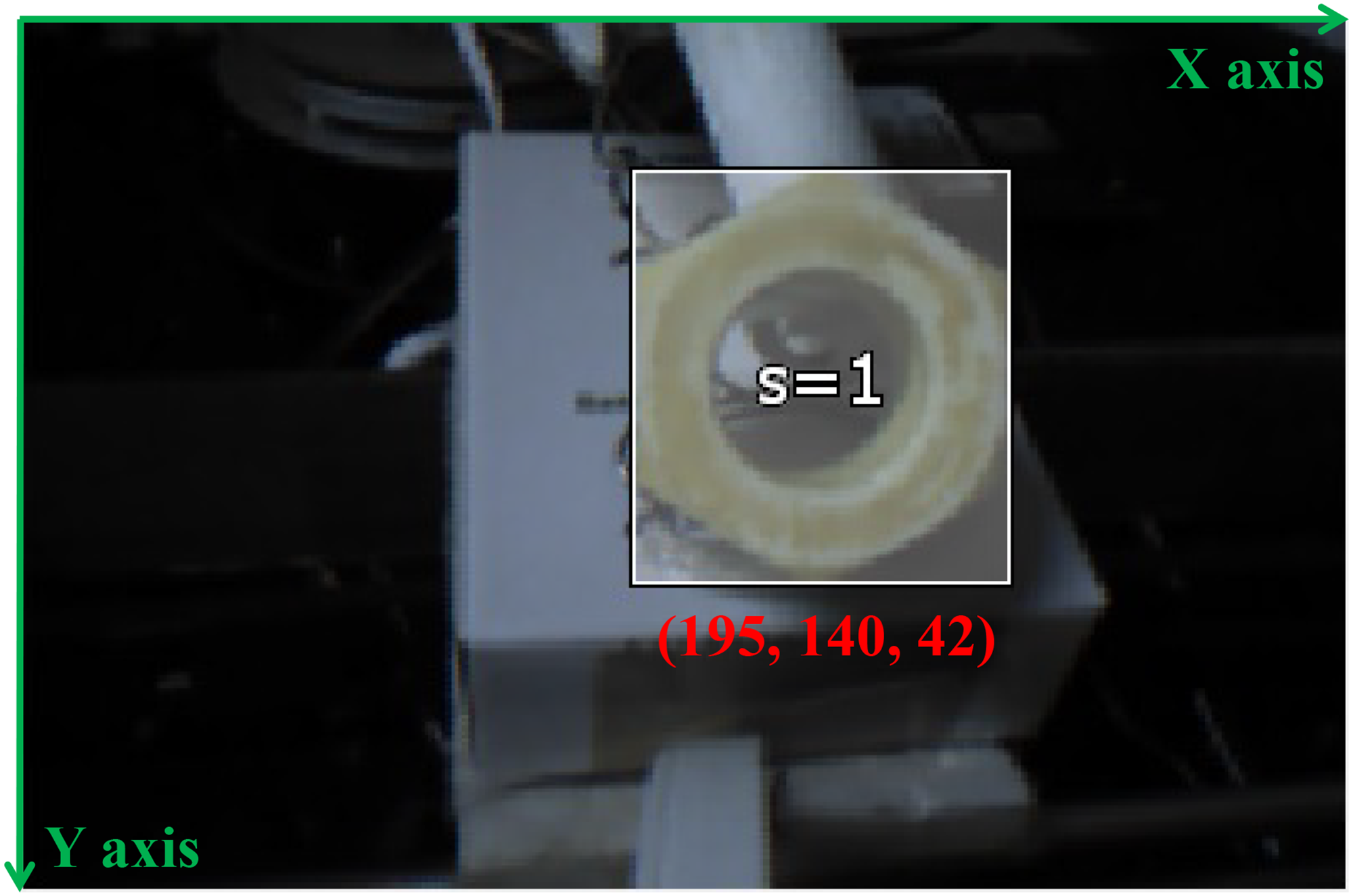
Recognition result of objective image.
The fuzzy rule design of this study is presented in Tables 1 to3. The 4-DOF robot arm was moved through fuzzy visual tracking control, continuously detected through CCD until the target center coordinate and distance reached the ideal position with tolerance, and then started to perform the gripping action.
Fuzzy rules of x-axis input.

Finally, we adopted the central method (COA) to defuzzify the fuzzy rule and calculate the center point of the block area after overlapping. Its formula
40
is:
Experiments
In this study, the 4-DOF robot arm is moved through fuzzy visual tracking control, and the CCD is used to continuously detect until the object is located at the target center coordinate and distance to reach the ideal position for the object to be grasped. According to the design of the fuzzy rules listed in Tables 1 to 3, the triangular membership function of the input was designed as follows:
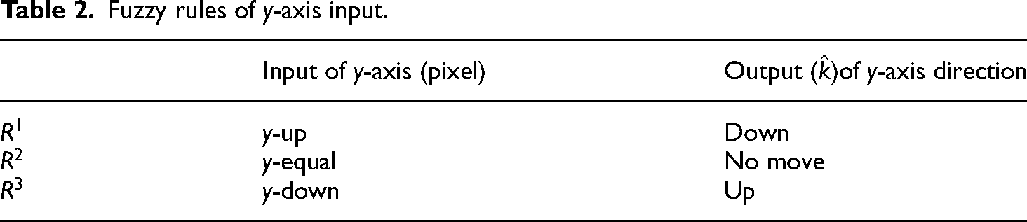
Fuzzy rules of y-axis input.
Fuzzy rules of distance input.


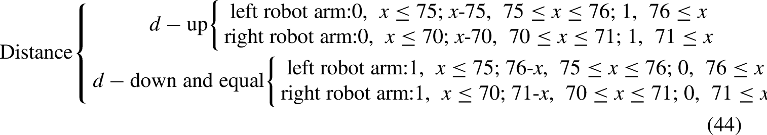
The membership function of the output was designed as follows:


Flowchart of automatic assembly through visual tracking and positioning.
To analyze the control results of the fuzzy visual tracking control, this study conducted a sequential analysis of the control effect of the robotic arm within 200 mm of the assembled clip by using CCDs based on the TVS method. Figure 9 shows the change in the x-position of the left arm during the automatic assembly through visual tracking and positioning. On the conveyor belt, the clips are transported from the left side of the left arm to the right side of the left arm, so the x-position (x = 44 pixels) detected by the left arm at the beginning was smaller than the target position (x = 140 pixels). Therefore, Joint 1 rotates along the right-hand rule according to the fixed coordinate system. The angle increases, and then gradually approaches the target position through the aforementioned steps and fuzzy control (x = 140 pixels). Joint 1 rotates against the right-hand rule, and the angle decreases; however, the x-position does not completely coincide with the target position, because Joints 3 and 4 are also detected by the CCD. The y- and distance-values cause the 4-DOF robot arm to perform interactive interference positioning control, which results in a value greater than the target position to float. Finally, x-position control of the left arm is completed under an allowable error of 10 pixels within a difference of 8 pixels.

Measurement result of x-position of the left 4-DOF robot arm during visual tracking and positioning.
Figure 10 shows the results of the y-position change in the left arm during automatic assembly through visual tracking and posting. Initially, the clip is slightly lower than the target position in the y-direction. The y-position (y = 180 pixels) detected by the CCD is larger than the target position (y = 75 pixels). Therefore, Joint 4 bends rapidly and the angle increases and then gradually approaches the target position through the above steps and fuzzy control and correct when the clip is on the upper side (y = 61 pixels) (Joint 4 is extended and the angle is reduced). However, the y-position does not completely coincide with the target position, because Joints 1 and 3 also cause the 4-DOF robot arm to perform interactive interference positioning control owing to the CCD detection of x- and distance-values, resulting in floating when the value is less than the target position. Finally, y-position control of the left arm is completed under an allowable error of 10 pixels with a difference of 6 pixels.

Measurement result of y-position of left 4-DOF robot arm during visual tracking and positioning.
Figure 11 shows the result of the change in the distance between the left arm and object during the automatic assembly through visual tracking and positioning. Initially, the object is slightly away from the jaws, so the distance (d = 202 mm) detected by the CCD based on the TVS method is considerably larger than the target position (d = 42 mm). Therefore, Joint 3 is slightly bent and the angle increases, and then close to the object. It is observed that the curve diagram exhibits the phenomenon of back and forth twists and turns. Because Joints 1 and 4 also detect the x- and y-values by the CCD, the 4-DOF robot arm performs interactive interference positioning control; however, by repeating the above steps and fuzzy control, it gradually reaches the target. The position is close, and the distance control of the left arm is completed under an allowable error of 4–5 mm in the floating.

Measurement result of distance between left 4-DOF robot arm and objective during visual tracking and positioning.
After completing the analysis of the data of the left arm detection, the next step is to analyze the x, y, distance of the right arm detection, and target position comparison. Figure 12 shows the results of the change in the x-position of the right arm during automatic assembly through visual tracking and posting. At the beginning, the conveyor belt transports the clips from the right side of the right arm to the left side of the right arm, so the initial x-position of the right arm detection (x = 309 pixels) is larger than the target position (x = 195 pixels). Therefore, Joint 1 rotates according to the anti-right-hand rule of the fixed coordinate system. The angle decreases, and then gradually approaches the target position through the above steps and fuzzy control. The x-position detected on the right arm (x = 183 pixels) is smaller than the target position (x = 195 pixel). It should be corrected as soon as possible (Joint 1 rotates according to the right-hand rule, and the angle increases); however, the x-position does not completely coincide with the target position because Joints 3 and 4 are also detected by the CCD. Therefore, 4-DOF robot arm performs interactive interference positioning control. Finally, under the allowable error of 10 pixels, difference of 7 pixels, the x-position control of the right arm is completed.
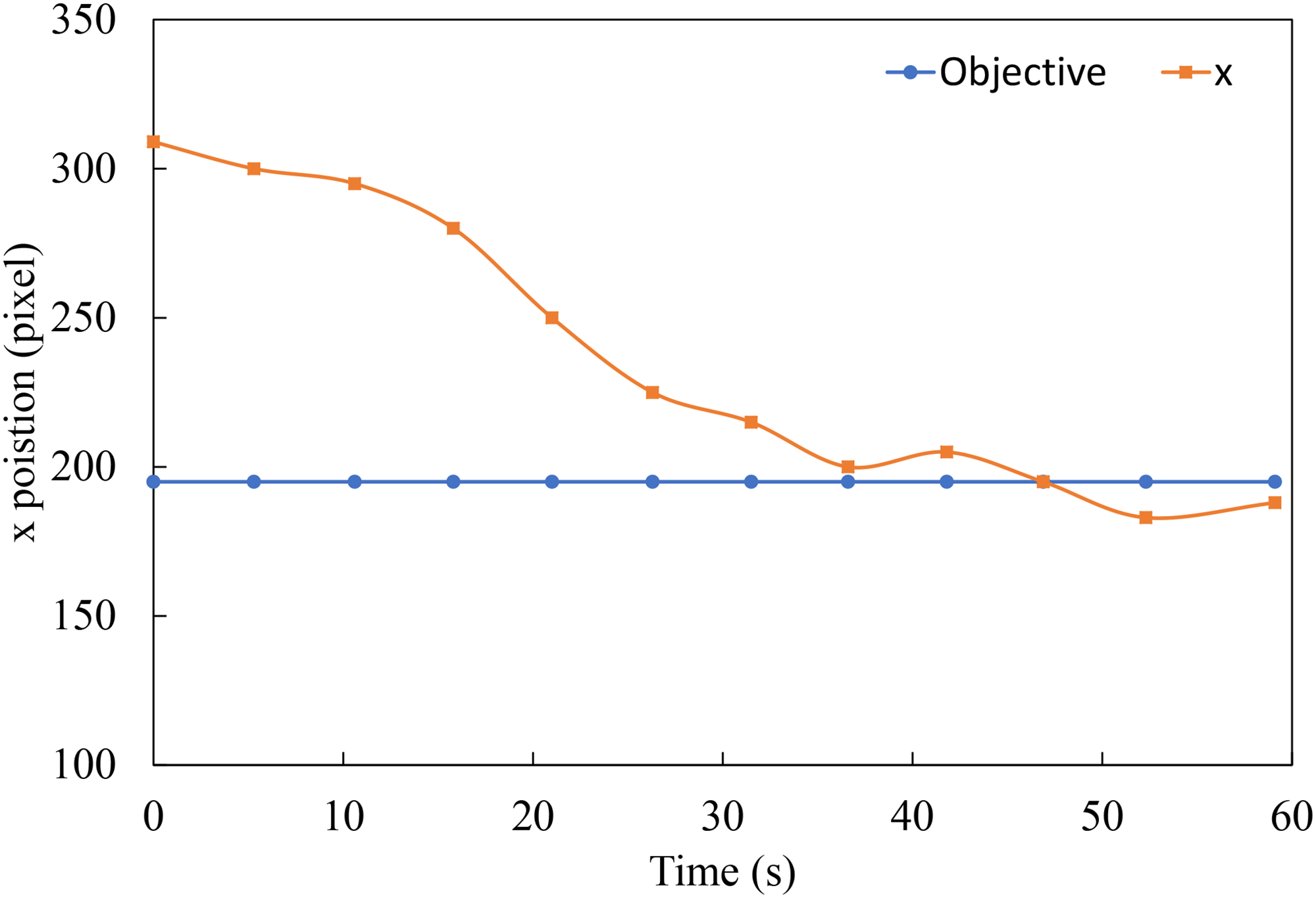
Measurement result of x-position of right 4-DOF robot arm during visual tracking and positioning.
Figure 13 shows the results of the y-position change in the right arm during automatic assembly through visual tracking and posting. Initially, the clip is slightly lower than the target position in the y-direction. The y-position (y = 179 pixels) detected by the CCD will be larger than the target position (y = 140 pixels); therefore, Joint 4 bends rapidly, and the angle will increase. Subsequently, through the aforementioned steps and fuzzy control, it gradually approaches the target position. When the clip is too high (y = 110 pixels), it is corrected (Joint 4 was extended, and the angle was reduced); however, the y-position did not completely coincide with the target position. Because Joints 1 and 3 are also detected by the CCD, the x- and distance-values cause the 4-DOF robot arm to perform interactive interference positioning control, resulting in floating when the value is less than the target position. Finally, the y-position control of the right arm is completed under an allowable error of 10 pixels, with a difference of 4 pixels.

Measurement result of y-position of right 4-DOF robot arm during visual tracking and positioning.
Figure 14 shows the result of the change in distance between the right arm and the object during automatic assembly through visual tracking and positioning. Initially, the gripper is slightly away from the gripper, so the distance (d = 210 mm) detected by the CCD based on the TVS method will be considerably smaller than the target position (d = 42 mm); therefore, Joint 3 is slightly bent, and the angle increases. It is then close to the clip. It is observed that the curve diagram exhibits the phenomenon of back and forth twists and turns. Because Joints 1 and 4 also detect the x- and y-values by the CCD, the 4-DOF robot arm performs interactive interference positioning control; however, by repeating the above steps and fuzzy control, it gradually reaches the target. The position is close, and the distance control of the right arm is completed under an allowable error of 2–5 mm in the floating.

Measurement result of distance between right 4-DOF robot arm and objective during visual tracking and positioning.
Figure 15 describes the five steps for the automatic assembly system to complete the task of screw and nut assembly through visually tracking the positioning of the dual robotic arms. After controlling the motor from the beginning to reach the designated initial position of the 4-DOF robot arm, the CCD is used to sense and identify the screws and nuts on the conveyor belt. Fuzzy control is used to move the gripper to the target position to clamp the screws and nuts on the aligned conveyor belt and control the dual robotic arms to track and align the screws and nuts, move forward and rotate each other, and complete the assembly task of the screws and nuts.
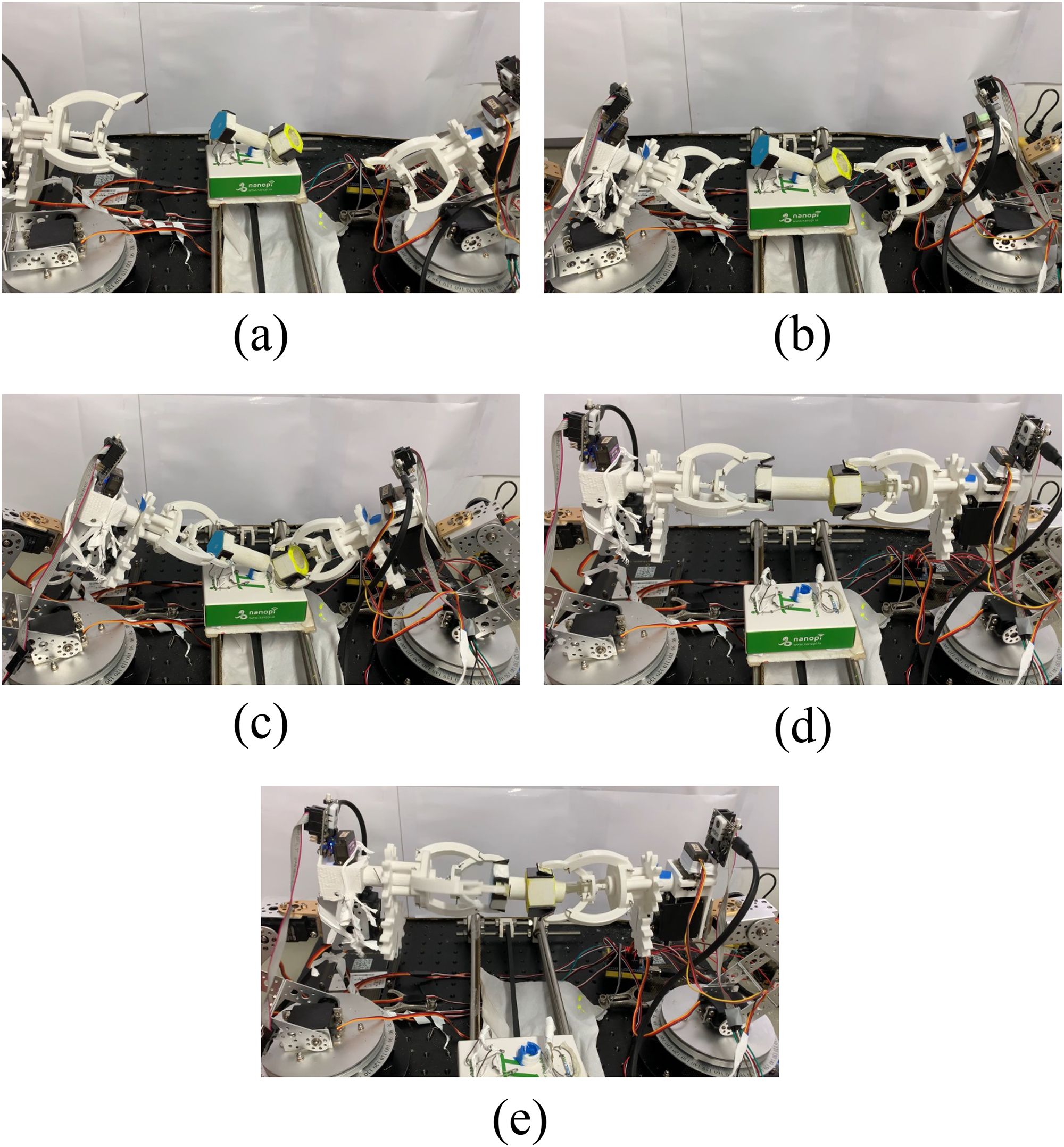
Five steps of the dual robotic arm system based on mutual visual tracking and positioning in the process of automatic assembly operation: (a) step one: dual robotic arm reaches the initial position; (b) step two: dual robotic arm completes the tracking of screw and nut; (c) step three: dual robotic arm performs grasping; (d) step four: dual robotic arm grips the screw and nut to reach the designated position; (e) step five: dual robotic arm completes the screw and nut rotation assembly.
Results and discussion
According to Figures 9 to 14, this study draws some conclusions. Firstly, the differences between the x positions detected by the left and right arms and the target positions are relatively large, the final-positioning errors of the left and right arms are 8 and 7 pixels by CCD measurements, respectively. Compared with the y positions and distances, the final-positioning errors of the x positions between the control positions and the target positions are even greater. It is speculated that owing to the interference of the controls of y positions and the distances and the influence of the speed of the conveyor belt, the control performance of the x-position of both arms is poor. Second, the difference between the y positions detected by the left and right arms and the target positions of two robot arms are different. The final-positioning error of the left arm is 6 pixels, and the final-positioning error of the right arm is 4 pixels. However, the difference is not significant, which is also owing to the difference in the positioning precision of the 4-DOF robot arm. In addition, the controls of the y positions of the left and right arms are slightly better than that of the x positions. This is presumed to be because the speed of the conveyor belt affects the measurement error in the y-axis direction, which is smaller than that in the x-axis direction. Third, there are differences between the distance values detected by the left and right arms and the target positions; the final-positioning error of the left arm is 4 mm, and the final-positioning error of the right arm is 2 mm. However, because the jaws are designed to be larger, they have larger gripping contact areas. Therefore, under allowable errors of x- and y-position of 10 pixels and distance of 5 mm, and the maximum error of tracking and positioning is 8%, the tracking, grasping, and assembly of the clip are completed.
Conclusion
The visual tracking positioning of the dual robotic arms proposed in this study is used in an automatic assembly system. The design includes a robotic arm and a gripper mechanism, supplemented by visual components for image recognition to provide gripping data. This study uses various technologies, such as, inverse kinematics, the TVS method, and fuzzy theory, to locate the target position, and successfully uses the dual robotic arms to clamp the screws and nuts on the moving conveyor belt and assemble them. In the design of the mechanism, 3D printing was used to manufacture the jaws, and a single motor was used to drive the operation of the jaws from the gear rack to ensure that the movements of the jaws are stable. Each motor with proper and sufficient torque is installed to establish the joints. In addition, a single robotic arm is equipped with a CCD. After continuously measuring the image of the grasped object and calculating the corresponding parameters, it automatically utilizes fuzzy visual tracking control to control the dual robotic arm system to grasp the screws and nuts on the moving conveyor belt with a tracking and positioning error of 8%, and the assembly action was completed. Therefore, the use of this study in the assembly task of a smart factory will significantly reduce the manpower for repetitive labor work. This reduces labor costs in the process and improves the efficiency of automated assembly.
Footnotes
Declaration of conflicting interests
The authors declared no potential conflicts of interest with respect to the research, authorship, and/or publication of this article.
Funding
The authors disclosed receipt of the following financial support for the research, authorship, and/or publication of this article: This work was supported by the National Science and Technology Council of Taiwan (grant number: 110-2221-E-019-058-MY2).
Author biographies
Bor-Jiunn Wen received his PhD degree from Department of Mechanical Engineering, National Chaio Tung University, Hsinchu, Taiwan, in 2012. He has been with the Department of Mechanical and Mechatronic Engineering, National Taiwan Ocean University, Taiwan, since 2015. His research interests include mechanics, control-system design, opto-mechatronics, optical and color measurements, automatic optical inspection, and machine learning. He has published more than 100 journal/conference papers, and 20 patents.
Ti -Wen Liu is working toward the master degree from Department of Mechanical and Mechatronic Engineering, National Taiwan Ocean University, Keelung, Taiwan. His current research interests include mechanics, control-system design, and opto-mechatronics.