
Abstract
There is still a lack of mature researches on the stability mechanism, influencing factors and control technology of the gob-side filling wall, and systematic researches on the cracking forms and characteristics of the stope roof and the stability of the filling wall are rather insufficient. This paper is aimed at investigating the deformation law of the filling wall under the large-span composite hinge fracture of the hard critical block and solving the difficulty that the large-span critical block lateral fracture poses to gob-side entry retaining. Research methods such as theoretical calculation, mechanical analysis, numerical simulation and field test were adopted comprehensively in this study. When the large-span critical block B is divided into two or three parts, its force on the immediate roof decreases with the increase in the number of segments. Meanwhile, as the number of segments grows, the displacement and axial stress of the filling wall both decrease gradually; the tensile failure weakens relatively, while the shear failure changes slightly. Moreover, both the number of shear cracks and the number of tensile cracks in the filling wall are positively correlated with the strain. When the critical block divided into four parts, the amount of lateral displacement is about 190 mm, and the axial displacement reaches the minimum (about 235 mm). The stability of the filling wall along the gob-side entry is closely related to the lateral fracture span of the stope roof. Under the lateral fracture of the hard critical block, a smaller span of the lateral fracture of the critical block corresponds to a smaller force on the filling wall and a weaker damage to the filling wall. The field test result verifies that cleaving the large-span critical block into smaller segments is conducive to reducing surrounding rock and filling wall deformation.
Keywords
Introduction
Since the 20th century, the technology of roadway support without coal pillars has been successfully applied to most domestic and foreign mines and a lot of achievements and practical experience have been obtained. In recent years, researches on the gob-side entry retaining technology are mainly conducted on its applicability and the roadway support control.1–5 By studying the deformation law and the control technology of roadway roof strata and filling wall, mutual effective support is applied for reducing the deformation and weighting of the gob-side entry retaining.6–14 Based on the characteristics of overlying strata movement, researchers have studied the pre-splitting pressure relief mechanism of the gob-side roof, 15 the movement law of overlying strata in the stope, the “X-O” failure mode of the stope roof, 16 the cutting and pressure relief failure mechanism of the roof, the deformation law of the roadway surrounding rock and the roadway support technology.17,18 Specifically, the successive stoping of the adjacent sublevel district working face (WF) in the gob-side entry retaining caused fracture of the stope roof, which affected crack characteristics and movement laws of the overlying strata.19,20 Additionally, he carried out a mechanical theory analysis of the stability of the arc-shaped triangle structure, and obtained its stability principle and effect. 21 Li established a numerical model of UDEC to explore the change law of the filling wall shearing and stretching affected by the subsidence of the critical block.22,23 His research promoted the further understanding of the characteristics of crack evolution and provided a reference for the stability control of the filling wall. Wang et al. 24 developed a roof mechanical model of the cut roof roadway, and proposed that basic dynamic pressure, roof support strength, and coal gangue support in the gob were the main factors affecting the crack development of the roof. Furthermore, he believed that the moment the roof cracked, damage was caused, and the depth of the crack was affected by the rock cohesion. Zhou et al. 25 thought that the filling wall could provide strong support to the roof to control its subsidence, and determined the necessary cutting resistance of the filling wall according to the maximum cutting force of the roof rock. Based on the mechanical model of gob-side entry retaining in a fully mechanized top coal caving face, Zhang et al. 26 theoretically calculated the support resistance of the filling wall according to different mechanical conditions of coal and rock mass, and deduced the corresponding formula. Moreover, they analyzed the relationship between the surrounding rock and the filling wall. Tan et al. 4 proposed a new type of “soft-hard” composite filling support form under the condition of hard roof in gob-side entry retaining, and determined the lateral support force and allowable compression of gob according to the mechanical model.
At present, there is still a lack of mature researches on the mechanism, influencing factors and control technology of the filling wall of stability in gob-side entry retaining, and systematic researches on the relationship between the span size, characteristics of the main roof fracture and the filling wall stability are rather insufficient. Based on previous research results, in this paper, a mechanical model was established, and the stress formula of the filling wall under different composite hinge fracture forms of critical block was deduced. Besides, the fracture characteristics of different composite hinge structures of critical block under the main roof large-span fracture in the gob-side entry retaining were analyzed. Through numerical simulation, the influence of different composite hinge fracture forms of large-span critical block on the displacement, stress and crack evolution of the filling wall was analyzed, and the relationship between the size of different lateral spans of critical blocks and the stability of the filling wall was obtained. The in-depth research on the lateral span of the critical block conducted in this paper has important guiding significance for the control of filling wall stability in gob-side entry retaining.
Engineering background
In the test mine, Xingwu Coal Mine, No. 4 and No. 5 coal seams with average thicknesses of 3.0 and 1.60 m are the main mining seams, and the average distance between the two seams is 6 m. To overcome the deficiencies brought by the conventional roadway layout and excavation and to solve the problem of serious waste of coking coal resources, the high-water material is used to realize the technology of gob-side entry retaining of the 5210 tail entry.
As shown in the plan of WF 5210 roadway layout in Figure 1, the upper part of the WF 5210 is adjacent to the gob; the northeast is adjacent to the WF 5209; and the southeast is close to the belt dip of the second mining area and the three dips of former No. 4 coal seam. No. 5 coal seam of the WF 5210 is of stable occurrence conditions with an average thickness of 1.60 m and an inclination angle of 2°–6°. There is no fault in this area where only a simple jointed and fractured structure is developed. The immediate roof and immediate floor are composed of sandy mudstone. The siltstone is the major component of the main roof and the main floor. The main roof is thicker. The specific geological conditions of the WF and rock strata are given in Figure 2.

The plan of WF 5210 roadway layout.

The comprehensive histogram of coal seam.
Analysis of the large-span critical block composite hinge fracture characteristics
Mechanism and conditions of the main roof large-span fractures
After the WF is exploited, cracks appear in the stope overlying strata, and those cracks form hinge points with one another. The broken blocks rotate and move down along the hinge points. At the same time, when the main roof span in the inclined stope direction exceeds its limit, the strength of the main roof also reaches the critical value, causing the cross section of rock with cracks to fracture, and the main roof of the stope also breaks. After the main roof breaks, the width of the critical block exceeds a certain value; the critical block no longer breaks; the gob is steadily compacted. At this moment, the large-span fracture of the main roof is formed. It is assumed in this paper that if the span of the critical block B is over 20 m after the main roof breaks (the periodic weighting interval of the main roof is usually 10–20 m), then the main roof is regarded to undergo a large-span fracture.
The related literature reveals that the thickness of the stope load layer mainly affects the height-to-length ratio of the main roof fractured block, and the length of the broken rock is inversely proportional to the thickness of the load layer. Besides, the length of the WF also has a certain effect on the height-to-length ratio of the main roof fractured block, and it is negatively correlated with the first weighting and the periodic weighting interval. The influence of mining height on the limit span of the main roof strata is simulated and analyzed with the aid of the numerical analysis software. The results show that the fracture span of the main roof depends on the mining height, that is, the greater the mining height is, and the smaller the fracture is. The relationship between the limit span L0 and the mining height b is as follows 27 :

Where H is the actual mining height, m; H0 is the traditional mining height, m; k is the decreasing coefficient of ultimate breaking distance of main roof (related to the increase of mining height), also known as the correction coefficient, and a large number of adjustment parameters are calculated by researchers through finite element software, and the coefficient is determined to be 1.3; L0 is the limit span, m; l0 is the estimation of the length of the main roof fractured block, m.
According to the above analysis, it is concluded that the smaller the mining height is, the easier it is to form a large span of the critical block. However, if the mining height is too small, the main roof fault will not be evident, and the bevel width of the large-span critical block will be approximately equal to its limit span. 28
Stress variation characteristics of the large-span critical block with the lateral fracture
Under the condition of the large-span fracture of the gob-side entry retaining main roof, as shown in Figure 3(a), on the roadway side, the large-span critical block B applies the major force on the immediate roof and the filling wall. On the gob side, after the main roof critical block B subsides and stabilizes, it compacts and keeps exerting pressure upon the gob, forming a hinge structure with the block C and the interaction force. The forces applied to the roadside filling wall are mainly composed of the gravity of the immediate roof, the main roof and the overlying strata, and the force of block B. Among them, the forces generated by gravity of the immediate roof, the main roof and the overlying strata cannot be changed, while the force exerted by the block B on the filling wall is alterable under certain conditions. By divided the block B into multiple parts to change its entirety, the gravity is correspondingly reduced, and each part transmits force to one another, in order to achieve the effect of pressure relief and reduce the force exerted on the immediate roof and the filling wall.

The profile of composite hinged structure of critical block B under large-span fracture of main roof, as follows: (a) the entire critical block B, (b) the critical block B is divided into two parts, and (c) the critical block B is divided into three parts.
As shown in Figure 3, the mechanical model profile of the gob-side entry retaining is established along the inclined direction of the WF. With the consistent properties and physical parameters of each stratum, the critical block B is regarded first as a whole and then is divided into two parts and at last is subdivided into three slices for force analysis to compare and analyze the force of the critical block B on the immediate roof under different conditions and its force on the filling wall.
In the case of the main roof large-span fracture, the force acted on the critical block B of different hinge fractures is analyzed, as shown in Figure 4. It is assumed that under the situation of the ideal fracture, the force exerted by the immediate roof on the critical block B on the roadway side is F1; the force exerted by coal gangue in the gob on B is F2; the interaction force exerted by the adjacent fracture block on B is F3; the uniform load applied by the overlying strata on B is q; and the weight of B is GB. Other forces are dismissed in the following formula derivation, and only the above main forces are considered.
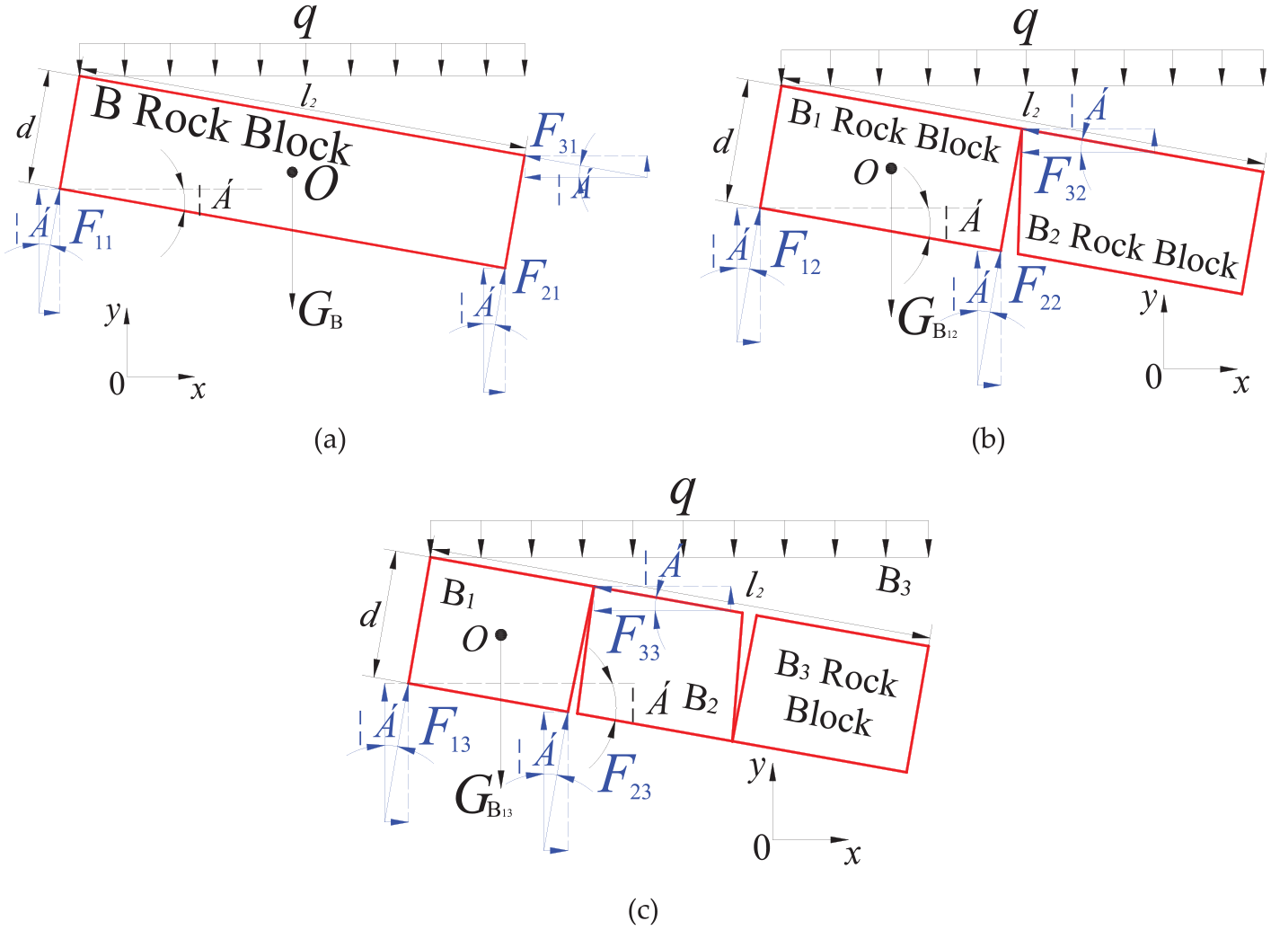
The force analysis of the critical block B of different structure conditions, as follows: (a) the entire critical block B, (b) the critical block B is divided into two parts, and (c) the critical block B is divided into three parts.
According to the force analysis of the critical block of different structure conditions, the balance equation is formulated to find out the force F1 exerted by the immediate roof on the critical block B under the conditions of B as a whole, B in two parts, B in three slices, respectively. Based on the force interaction principle, the force F1′ of B on the immediate roof is obtained, and then the force of B on the filling wall is also attained. It is supposed that the length l2, thickness d, and mechanical properties of the critical block B are the same in all the three cases, and the positive directions of the X-axis and the Y-axis are dictated.
As shown in Figure 4(a), a force analysis is performed on the entire critical block B, and the balance equation is:
In the horizontal direction,

Where F11 is the force that the immediate roof exerts on the critical block B on the roadway side, kN; F21 is the force the gangue acting on the critical block B in the gob, kN; F31 is the force of the adjacent block C on the critical block B at the occlusion point, kN; α is the rotation angle of critical block B, °.
In the vertical direction,

Where GB is the gravity of the critical block B, kN; l2 is the length of the critical block B, m; q is the uniform load applied by the overlying strata on the critical block B, kN/m2.
Let the forces F11, F21, F31, gravity GB and the uniform load q take moments from the center of gravity O of the critical block B. Since the gravity GB and the uniform load q pass through the center of gravity O, the moment is 0. Then the forces F11, F21, and F31 can be calculated by taking moments of the barycenter O of the critical block B.

Where d is the thickness of the critical block B, m.
In light of equations (2), (3), and (4), under the immediate roof large-span fracture, the force F11 applied by the immediate roof on the entire critical block B is:

Next, as shown in Figure 4(b), the critical block B is divided into two parts for the force analysis. The balance equation is as follows:
In the horizontal direction,

Where F12 is the force that the immediate roof exerts on the block B1 on the roadway side, kN; F22 is the force the gangue acting on the block B1 in the gob, kN; F32 is the force of the adjacent block B2 on the block B1 at the occlusion point, kN.
In the vertical direction,

Where
The forces F12, F22, and F32 can be obtained by taking moments of the barycenter O of the block B1.

According to equations (6), (7), and (8), under the condition of main roof large-span fracture, the force F12 acting on the block B1 by the immediate roof is:

Finally, as shown in Figure 4(c), the critical block B is divided into three parts for the force analysis. The balance equation is as follows:
In the horizontal direction,

Where F13 is the force that the immediate roof exerts on the block B1 on the roadway side, kN; F23 is the force the gangue acting on the block B1 in the gob, kN; F33 is the force of the adjacent block B2 on the block B1 at the occlusion point, kN.
In the vertical direction,

Where
The forces F13, F23, and F33 can be obtained by taking moments of the barycenter O of the block B1.

In term of equations (10), (11), and (12), under the condition of main roof large-span fracture, the force F13 acting on the block B1 by the immediate roof is:

Based on the above equation derivation and analysis, as GB >
Therefore, the critical block of different composite hinge fractures exerts different forces on the immediate roof. As can be seen from Figure 3, according to the force transitivity, the immediate roof of different composite hinge fractures exerts varying forces on the roadway-side filling wall. It is proved by theoretical analysis that, when the critical block B breaks into a complete large-span block during the gob-side entry retaining, it exerts a large force on the immediate roof and further on the roadway-side filling wall. When the large-span critical block B breaks into two or three equal parts, its force on the immediate roof decreases and is less than that before the break. What’s more, the force of the critical block B acting through the immediate roof on the filling wall also declines as the number of the large-span critical block divisions increases. Therefore, theoretically, it is further demonstrated that the force exerted on the filling wall along the gob-side entry retaining by the large-span critical block B of composite hinge fractures is smaller than that when the critical block is intact.
Deformation law of the filling wall under the condition of the large-span critical block lateral fracture
Numerical model and scheme
Taking the geological condition and production situations of Xingwu Coal Mine as the background, the Universal Distinct Element Code (UDEC) numerical simulation analysis method is adopted to establish a Trigon numerical model of a main roof large-span fracture in the inclined direction of the gob-side entry retaining stope. The size of the model is 160 m in the horizontal x direction and 60 m in the vertical y direction, as shown in Figure 5.

The model of UDEC numerical simulation.
According to the actual geological conditions in the field, the Mohr-Coulumb constitutive model is employed in the numerical model simulation analysis. The contact surface of the block conforms to the Mohr-Coulumb yield criterion, and the Strain Softening model is applied for the filling wall.29,30 In addition, the vertical stress applied by the upper boundary of the numerical model is calculated based on the model boundary distance of 364 m from the ground and the vertical stress gradient of 0.025 MPa/m. It is obtained that the vertical stress and the initial geostress, which are both downward vertically, are 9.1 and 10.6 MPa, respectively. Specifically, the physical and mechanical simulation parameters of coal and rock mass in the numerical model are shown in Table 1.
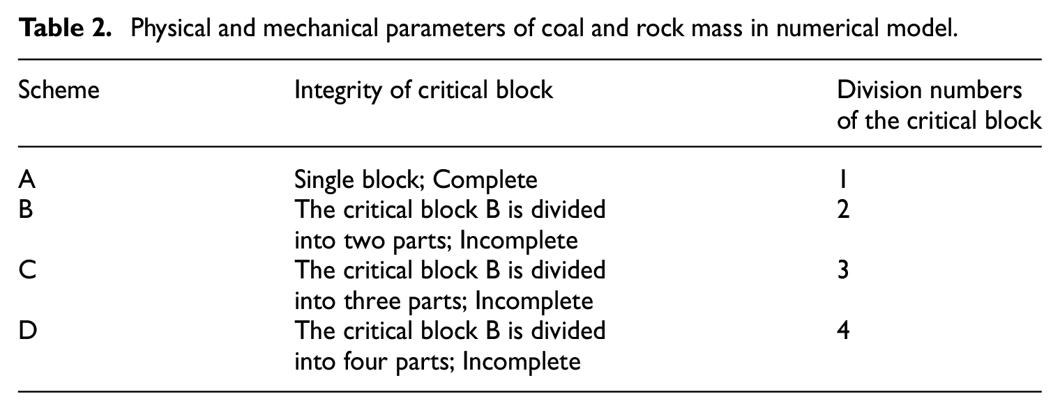
Physical and mechanical parameters of coal and rock mass in numerical model.

In order to study and analyze the deformation law of the filling wall under the condition of composite hinge fractures of the gob-side entry retaining main roof large-span critical block, the large-span critical block is first considered as a whole and then is divided equally into two parts, and even three and four slices. For comparative analysis, different numerical simulation schemes are proposed, as shown in Table 2. The filling wall is made of high-water filling material; its reasonable width is 1.2 m; and the water-cement ratio is set as 1.5:1.
Physical and mechanical parameters of coal and rock mass in numerical model.
Variation laws of the filling wall displacement and stress
Displacement variation law
According to different simulation schemes, the main roof critical block with large-span fracture is first regarded as an entity and then is evenly divided into two, three, and even four parts to perform the simulation analysis on the variation of the filling wall displacement under the condition of different hinge forms (different numbers of the critical block divisions) of the gob-side entry retaining large-span critical block, including the variation law of the lateral displacement and the axial displacement produced by the deformation of the filling wall, as shown in Figure 6.

Displacement nephogram of filling wall under different fracture hinge structures of critical block, as follows: (1) Lateral displacement, including the critical block: (a) complete block, (b) be divided into two parts, and (c) be divided into three parts, and (d) be divided into four parts. (2) Axial displacement, including the critical block: (a) complete block, (b) be divided into two parts, (c) be divided into three parts, and (d) be divided into four parts.
It can be seen from Figure 6 that the lateral displacement and axial displacement nephograms of the filling wall both differ under the condition of the different hinge forms of the critical block. This means the different division numbers of the critical block has a certain effect on the deformation of the filling wall. For the lateral displacement nephogram, a set of the same color is used to represent the amount of displacement variation in the same range, and for the axial displacement nephogram, another set of the same color is employed to represent the amount of displacement variation in the same range. The details are given as follows:
With regard to the lateral displacement of the filling wall, the deformation amount reaches the maximum value on the roadway side, especially significant at the upper part of the filling wall. Besides, the range of the maximum displacement (greater than 200 mm) before the critical block division is substantially larger than that after the division. When the critical block is cleaved into four parts, the maximum displacement does not exceed 200 mm. Moreover, the maximum value and range of the displacement (150–200 mm) generated when the block is divided into four parts is significantly smaller than that of the block in three parts. On the gob side, it is easy to form the large deformation at the middle and upper parts of the filling wall. When the displacement is over 100 mm, the range of the displacement constantly decreases as the number of critical block divisions increases.
In respect of the axial displacement of the filling wall, the maximum value of the displacement amount is prone to appear at the upper part of the filling wall and the deformation amount at the bottom is extremely small. The range of displacement (over 350 mm) at the upper part of the filling wall reaches the peak value before the division and is the smallest when the critical block is divided into four parts. The range of displacement (0–50 mm) at the bottom of the filling wall is the largest before the division and reaches the minimum when the critical block is cleaved into four parts. The maximum displacement value and the corresponding range on both sides of the filling wall dwindle with the growing number of critical block divisions.
Based on the above analysis, when the critical block is divided into four parts, the displacement amount and range of the filling wall are relatively small, and the corresponding damage and deformation are also limited. The maximum lateral and axial displacements of the filling wall at the same position when the critical block is separated in different numbers are summarized. The change trend is shown in Figure 7.
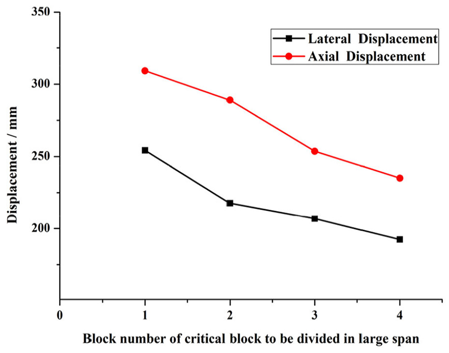
Displacement variation of filling wall.
It can be seen from Figure 7 that the lateral displacement and axial displacement caused by the deformation of the filling wall are the largest (about 254 and 309 mm, respectively) before the critical block is divided. As for the lateral displacement of the filling wall, the number of critical block divisions increases, the amount of lateral displacement decreases. When the block divided into four parts, the amount of lateral displacement is about 190 mm. With regard to the axial displacement of the filling wall, its value has a negative correlation with the number of critical block slices, and the axial displacement reaches the minimum (about 235 mm) when the block is cleaved into four partitions. When the critical blocks are divided into the same number of slices, the axial deformation of the filling wall is larger and more serious than its lateral deformation.
Stress variation law
According to different simulation schemes, the main roof critical block with large-span fracture is first regarded as an entity and then is evenly divided into two, three, and even four parts to perform the simulation analysis on the stress change of the filling wall under the condition of different hinge forms (different number of the critical block divisions) of the gob-side entry retaining large-span critical block, including the variation law of the lateral stress and the axial stress produced by the deformation of the filling wall, as shown in Figure 8.

Stress nephogram of filling wall under different fracture hinge structures of critical block, as follows: (1) Lateral stress, including the critical block: (a) complete block, (b) be divided into two parts, (c) be divided into three parts, and (d) be divided into four parts. (2) Axial stress, including the critical block: (a) complete block, (b) be divided into two parts, (c) be divided into three parts, and (d) be divided into four parts.
It can be seen from Figure 8 that the lateral stress and axial stress nephograms of the filling wall both differ under the condition of the critical block different hinge forms. This means the different division numbers of the critical block has a certain effect on the lateral and axial stress of the filling wall when the deformation occurs. For the lateral stress nephogram, a set of the same color is used to indicate the amount of stress change in the same range, and for the axial stress nephogram, another set of the same color is employed to imply the amount of stress change in the same range. The details are exhibited as follows:
No matter how many parts the block is divided into, the maximum value of the filling wall lateral stress occurs at the top of the filling wall on the gob side and the bottom of the filling wall both on the roadway side and on the gob side. The stress along the interconnect of the three locations is relatively large, and the interconnect is approximately in the shape of the Chinese character “人” When the critical block is divided into three parts, the stress is relatively large in the range of 3.0–3.5 MPa, and the stresses on the left and right sides of the filling wall are relatively small. When the critical block is divided into four parts, the lateral stress value and its range near the top of the filling wall on the gob side are the smallest, which implies the stress value and range are inversely proportional to the number of critical block divisions.
No matter how many parts the block is divided into, the maximum value of the filling wall axial stress occurs at the bottom and near the axial central position closer to the gob side. On the roadway side of the filling wall, the axial stress is smaller. Besides, the stress is smaller before the critical block is cleaved, and when it is divided into two parts, the stress is still at a lower level while the minimum stress range is comparatively larger. On the gob side of the top of the filling wall, the axial stress value and range of overlying strata on the filling wall are smaller before the critical block is divided. As the number of the divisions increases, the stress range declines successively.
According to the above analysis, the peak stress value and range of the filling wall are smaller when the critical block is divided into four parts, and the corresponding damage and deformation are also smaller. The maximum lateral and axial stress values of the filling wall under different numbers of critical block divisions are shown in Figure 9.
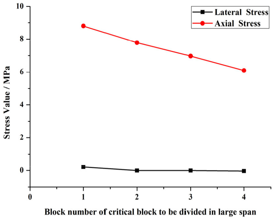
Stress variation of filling wall.
It can be observed from Figure 9 that the number of the large-span critical block division plays a significant role in the axial stress of the filling wall, and the axial stress at the top of the filling wall decreases as the number of critical block division increases. The lateral stress on the filling wall is slightly related to the critical block divisions. As for the lateral stress of the filling wall, the stress value of different critical block divisions is lower than 0.3 MPa in all the above cases and is at relatively higher level of 0.22 MPa when the block is not cleaved. When the critical block is regarded as an entity, the axial stress of the filling wall reaches its peak value, about 8.8 MPa. When the block is divided into two, three and four parts, the axial stress decreases in turn to about 7.8, 7.0, and 6.1 MPa, respectively.
Variation laws of the filling wall displacement and stress
Distribution of the plastic zone
The distribution law of the filling wall plastic zone under the condition of different hinge forms of the critical block is displayed in the Figure 10. When the critical block is divided into different parts, the filling walls in the same size are selected for the plastic zone analysis, which contributes to the accuracy of the analysis result.

Plastic zone distribution of filling wall, including the critical block: (a) complete block, (b) be divided into two parts, (c) be divided into three parts, and (d) be divided into four parts.
It can be known from the observation that under different numbers of critical block divisions, the plastic zones of the filling wall mainly occur around its periphery and the inner diagonals. Besides, the shear failure concentratedly appears at the interconnect of the middle and lower parts of the filling wall and the bottom corners in the shape of the Chinese character “人” Furthermore, the tensile failure is concentratedly distributed at the interconnect of the right upper corner and the left bottom corner of the filling wall. As the critical block is divided into more parts, the extent of tensile failure declines while the shear failure changes slightly. After the critical block is divided into two parts, the shear failure decreases while the tensile failure increases, compared with the situation when the critical block is an entity. When the block is cleaved into three parts, the shear failure and tensile failure both dwindle. When the block is divided into four parts, the increment of the shear failure is very small while the tensile failure is drastically reduced.
Change law of the shear cracks
In the same simulation calculation time, the numbers of the filling wall shear cracks in different schemes under the same strain are comparatively analyzed,31,32 and the relationship between the filling wall strain and the shear cracks in the case of different numbers of the large-span critical block divisions is obtained and shown in Figure 11.

Strain and shear cracks relationship curve.
It can be found from Figure 11 that the number of critical block divisions has a certain effect on the strain-shear crack relationship of the filling wall. When the critical block is cleaved into different slices, the number of shear cracks of the filling wall is directly proportional to the magnitude of the strain. After the strain becomes greater than 0.01, the number of shear cracks under different critical block partitions increases with the strain, but the growth rate slows down with the increasing divisions of the critical block. After the strain becomes greater than 0.04, under the same strain, the number of filling wall shear cracks is proportional to the number of the critical block segments. For example, when the strain is 0.09, they satisfy the linear relationship N = 14.3x + 465.5 (where N is the number of shear cracks; x is the number of the critical block segments). And the growth rate of the shear cracks and the maximum number of cracks both rise with the increment of the number of critical block divisions. Moreover, the number of shear cracks reaches its peak value 667 when the critical block is cleaved into four parts.
Change law of the tensile cracks
In the same simulation calculation time, the numbers of the filling wall tensile cracks in different schemes under the same strain are comparatively analyzed, and the relationship between the filling wall strain and the tensile cracks in the case of different numbers of the large-span critical block divisions is obtained and shown in Figure 12.
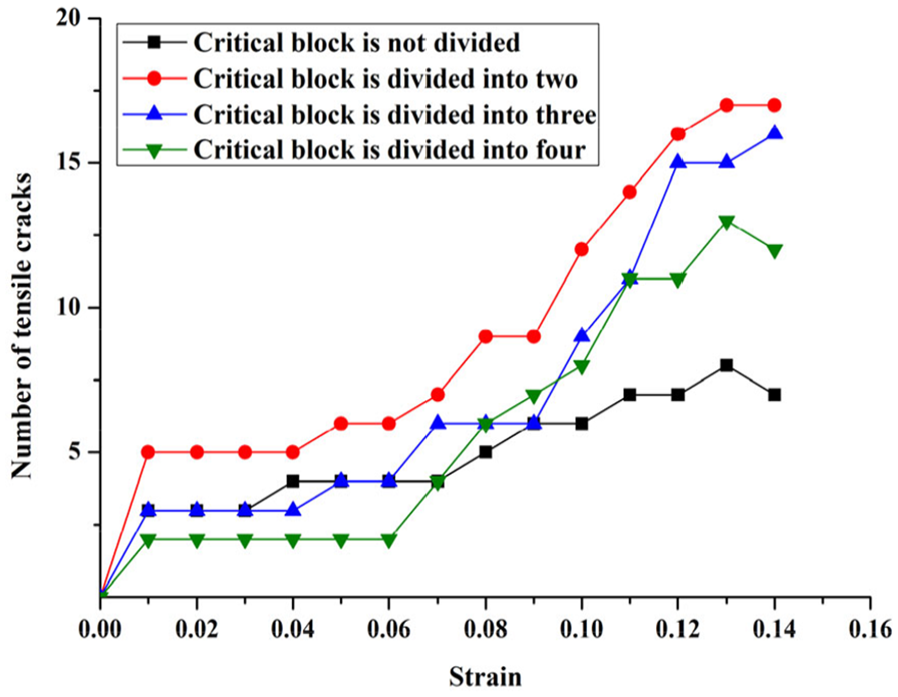
Strain and tensile cracks relationship curve.
As can be seen from Figure 12, compared to the strain-shear crack relationship of the filling wall, the strain-tensile crack relationship of the filling wall is less affected by the number of critical block divisions. When the critical block is divided into different parts, the number of tensile cracks in the filling wall increases with the increase of strain. Before the strain becomes greater than 0.01, the growth rate of the cracks is relatively smaller when the critical block is divided into four slices. When the strain is between 0.01 and 0.06, the growth rate of the number of cracks is approximately the same under different numbers of the block partitions. After the strain becomes greater than 0.06, the growth rate of the cracks when the block is regarded as an entity is relatively slower than that when the critical block is divided into more parts.
Damage change law
Based on the above curve analysis of the strain-shear crack relationship and the strain-tensile crack relationship of the filling wall, it is concluded that the different numbers of the critical block divisions have a certain effect on the crack development of the filling wall. Specifically, dividing the critical block into more parts can promote the development and increment of cracks. The damage degree of the filling wall is estimated based on the ratio of the sum of the lengths of shear cracks and tensile cracks to the total length of all cracks. In numerical simulation, the sum of the lengths of shear cracks and tensile cracks and the total length of all cracks is monitored by compiling the code command. In this way, the index for judging the damage degree of the filling wall is calculated.
According to the numerical simulation, the change curve of the total damage degree of the filling wall under different numbers of divisions is shown in Figure 13. In numerical simulation, other conditions remain unchanged except the length of the critical block in the model. Therefore, when the critical block is divided into different segments (i.e. when the length of the critical block varies), the damage degree of the filling wall differs.

Strain and damage relationship curve.
It can be seen from Figure 13 that under different numbers of divisions, the damage degree of the filling wall multiplies with the increment of the strain. The damage growth rate is rapid before the strain exceeds 0.01. After the strain becomes greater than 0.01, the growth rate is lower, but the damage still multiplies linearly with the strain. Generally speaking, the more the critical block divisions is, the greater the damage to the filling wall is. Under the same strain, the damage degree of the filling wall is the smallest (0.52) when the critical block is an entity, while it reaches the maximum (about 0.57) when the block is divided into four parts.
Hydraulic fracturing and mine pressure observation of the gob-side entry retaining
In the WF 5210 tail entry of the test coal mine, the gob-side entry retaining is retained. After the WF stoping, a large-span fracture of about 25 m is formed on the roof of the stope near the tail entry. In order to solve the problem of the large-span critical block damaging the filling wall, it is decided to cut the roof and divide the large-span critical blocks into small parts by using the directional hydraulic fracturing technology, so as to reduce its function on the deformation of the surrounding rock and the roadway-side filling wall.
According to the practical production conditions of the WF 5210, boreholes are arranged in the 5210 tail entry, and the large-span critical block is cut and broken to reduce its damage to the surrounding rock and the filling wall. According to the numerical simulation results of the different composite hinge forms of the critical block and the actual on-site situation, inclined boreholes are drilled from the roadway roof to the WF. The depth of the inclined boreholes is 15 m; the distance between each borehole is 10 m; and the horizontal angle is 60°, as shown in Figure 14.
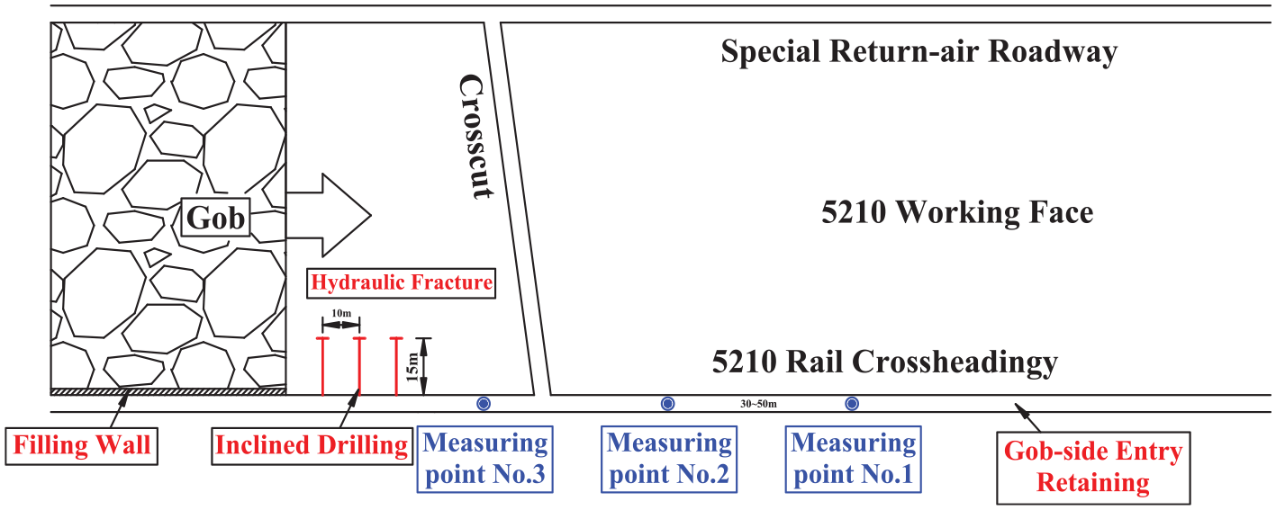
The hydraulic fracturing layout plan of WF 5210.
After the large-span critical block is cut and broken by hydraulic fracturing technology in the 5210 tail entry, measuring points 1#, 2#, and 3# are arranged at a certain distance. During the stoping and advancement of the WF, the relative deformation of the two sides of the roadway, the relationship between the load on the filling wall and the distance from the measuring point to the WF are monitored at the corresponding measuring points, as shown in Figure 15.

Relative deformation curves of two sides of roadway, as follows: (a) displacement variation relationship, and (b) stress variation relationship on filling wall.
It can be known from Figure 15(a) that the change trends at the three measurement points are approximately the same with the change trend of roadway roof and floor deformation. When the WF stoping is executed to the measurement point, the relative deformation amount reaches a larger value. When the WF stoping is further advanced over the measuring points, the relative deformation amounts of the two sides at three measuring points gradually increase to stable and constant maximum values of 246, 281, and 290 mm, respectively, as its distance from the stoping of the WF increases. Besides, when the maximum values of relative deformation of the two sides at measuring points 1#, 2#, and 3# are observed, the distances from the WF to the measuring points are 90, 120, and 150 m, respectively.
It can be found from Figure 15(b) that when the distance between the WF stoping and the measuring points changes from 40 to 0 m, the stress on the filling wall surges from the minimum value to a larger value. The larger values of measuring points 1#, 2#, and 3# are about 7.0, 8.6, and 9.4 MPa, respectively. When the WF stoping is over the measuring point and the distance between the WF and the measuring points is 0–55 m, the stresses at the measuring points 1#, 2#, and 3# all reach their maximums at the distance of 55 m, which are about 11, 12, and 12.9 MPa, respectively. When the distance exceeds 55 m, the stresses on the roadway-side filling wall decrease to relatively stable values of 7.8, 8.3, and 9.5 MPa, respectively.
According to the above analysis, after cutting the large-span critical blocks in the oblique direction of the WF 5210, the deformation of the surrounding rock along the tail entry and the stress on the roadway-side filling wall are relatively small within the allowable deformation range. At the same time, it is also concluded that cutting large-span critical blocks into small parts (smaller in lateral span) is conducive to improving the stability of the filling wall, prolonging the life of the filling wall, reducing the cost of the colliery, and achieving certain economic benefits.
Conclusions
This paper is focused on the investigation of the relationship between the stability of roadway-side filling wall in the gob-side entry retaining and the lateral fracture span of the stope roof. A systematic study was carried out on the characteristics of the different composite hinge fractures of the large-span critical block and the deformation law of the filling wall under different composite hinge fracture forms. Specifically, the effects of the critical block with different lateral spans on the stress, displacement and fracture evolution of the filling wall were researched on. The following main conclusions were drawn:
The stress of the large-span critical blocks of different composite hinge fractures is analyzed. The force F1′ on the immediate roof exerted by the critical block B divided in two and three parts is smaller than that exerted by the critical block B as an entity. Therefore, it is concluded that the force of the critical block B broken into small parts on the roadway-side filling wall is smaller than that of the complete block.
Numerical simulation results of the large-span critical block of different composite hinge fractures show that the lateral displacement and axial displacement of the filling wall decrease with the increase of the number of the critical block divisions, and the axial deformation of the filling wall is more serious. Besides, the number of the large-span critical block division plays a significant role in the axial stress of the filling wall, and the axial stress at the top of the filling wall declines as the number of the critical block partitions increases. The lateral stress to which the filling wall is subjected is less related to the critical block divisions.
The plastic zones of the filling wall mainly occur around its periphery and the inner diagonals. Besides, the shear failure concentratedly appears at the interconnect of the middle and lower parts of the filling wall and the bottom corners in the shape of the Chinese character “人” Furthermore, the tensile failure is concentratedly distributed at the interconnect of the right upper corner and the left bottom corner of the filling wall. As the large-span critical block is divided into more parts, the extent of tensile failure weakens while the shear failure changes slightly.
The number of shear cracks and the number of tensile cracks in the filling wall are both positively correlated with the strain. After the strain becomes greater than 0.04, the number of shear cracks in the filling wall is proportional to the number of the critical block divisions under the same strain, and the number of tensile cracks in the filling wall is smaller under different block divisions. The damage degree of the filling wall increases with the increment of the strain. Generally speaking, the larger the number of critical block segments is, the greater the damage degree is.
A case study on the 5210 tail entry in Xingwu Coal Mine is carried out. Under the large-span critical block fractures in the gob-side entry retaining, after cutting the overlying large-span critical block of the WF 5210, the surrounding rock deformation of the tail entry and the stress of the filling wall are relatively small within the allowable deformation range, and the deformation resistance and control effect are significantly improved. The field test result verifies that dividing the large-span critical block is conducive to stabilizing the filling wall.
Footnotes
Declaration of conflicting interests
The author(s) declared no potential conflicts of interest with respect to the research, authorship, and/or publication of this article.
Funding
The author(s) received no financial support for the research, authorship, and/or publication of this article.