
Abstract
Although a significant amount of research on robot joint reducer was conducted, there are few systematic investigations on a novel joint reducer adopting inner worm-gear plane enveloping drum worm drive. To satisfy the development of modular robot joint, the primary objective of this paper was to systematically investigate the drum worm drive adopted in the novel joint reducer with integrated structure of drive, transmission, and support in the following aspects: meshing theory, design, analysis, and manufacture. According to the gear meshing theory, mechanical design method, classical mechanics, finite element method, and machining principle of virtual center distance, the systematic investigations around the drum worm pair applied in the novel joint reducer were conducted including the macro and micro meshing theory, structure design, mechanical and contact properties analyses, and manufacturing method. The novel joint reducer’s integrated structure was designed, and the drum worm pair’s mechanical and contact properties analyses were conducted, which showed: (1) the worm’s bending stress and deflection, worm-gear teeth’s shear stress and bending stress as well as the maximum contact stresses were all below their corresponding allowable values; (2) the maximum contact stresses appeared at the engage-in position of the worm pair opposing to the engaging-out position where the largest contact areas appeared. Then the manufacturing of drum worm’s spiral tooth was conducted via the modified 4-axis linkage CNC grinder according to the conjugate motion. Finally the novel joint reducer’s industrial prototype was assembled. The novel joint reducer with integrated structure of drive, transmission and support was designed and manufactured for the first time. The flowchart of design and manufacture of the reducer’s drum worm pair in this process was formulated, which provides a new insight on the research of joint reducers as well as other fields.
Introduction
The joint is one of important modules of the robot, which has shown a development trend of modularization nowadays, and the integration degree of motor and reducer determines the modularity of robot joint. Harmonic transmission1,2 and RV transmission 3 are most widely used in robot reducers, but they are hard to manufacture due to their complicated structures. Compared with above transmissions, in addition to advantages of large transmission ratio, compact structure, small volume, and high accuracy transmission, worm drive is also characteristic with self-locking function and simple structure, therefore researchers studied the application of it in robot joints. Otani et al. 4 and Choi et al. 5 proposed to equip the worm drive in the knee joint of a bipedal humanoid robot and the pitch joint of the shoulder and elbow of a military rescue robot, respectively. As well as, Jackson et al. 6 published the patent which described a kind of robot arm whose joint adopting worm-gears. However, the worm drive is used as one component cooperating with other transmissions in the above joints all driven by outside motors, yet there are few applications of built-in motors presently.
With the development of the modularization of robot joints,7–10 recently we have proposed a novel precision joint reducer with a built-in motor, named as inner worm-gear plane enveloping drum worm drive reducer, which is characterized with the integrated structure of drive, transmission and support. As show in Figure 1, the reducer adopts the orthogonal internal meshing worm pair to realize the transmission, it is driven by an external rotor motor built into the hollow worm, and main components such as motor and worm are located within the worm-gear ring. In addition, worm-gear seats, brackets, bearings, etc. are utilized to support the reducer, without the need for the gearbox with complicated structure.
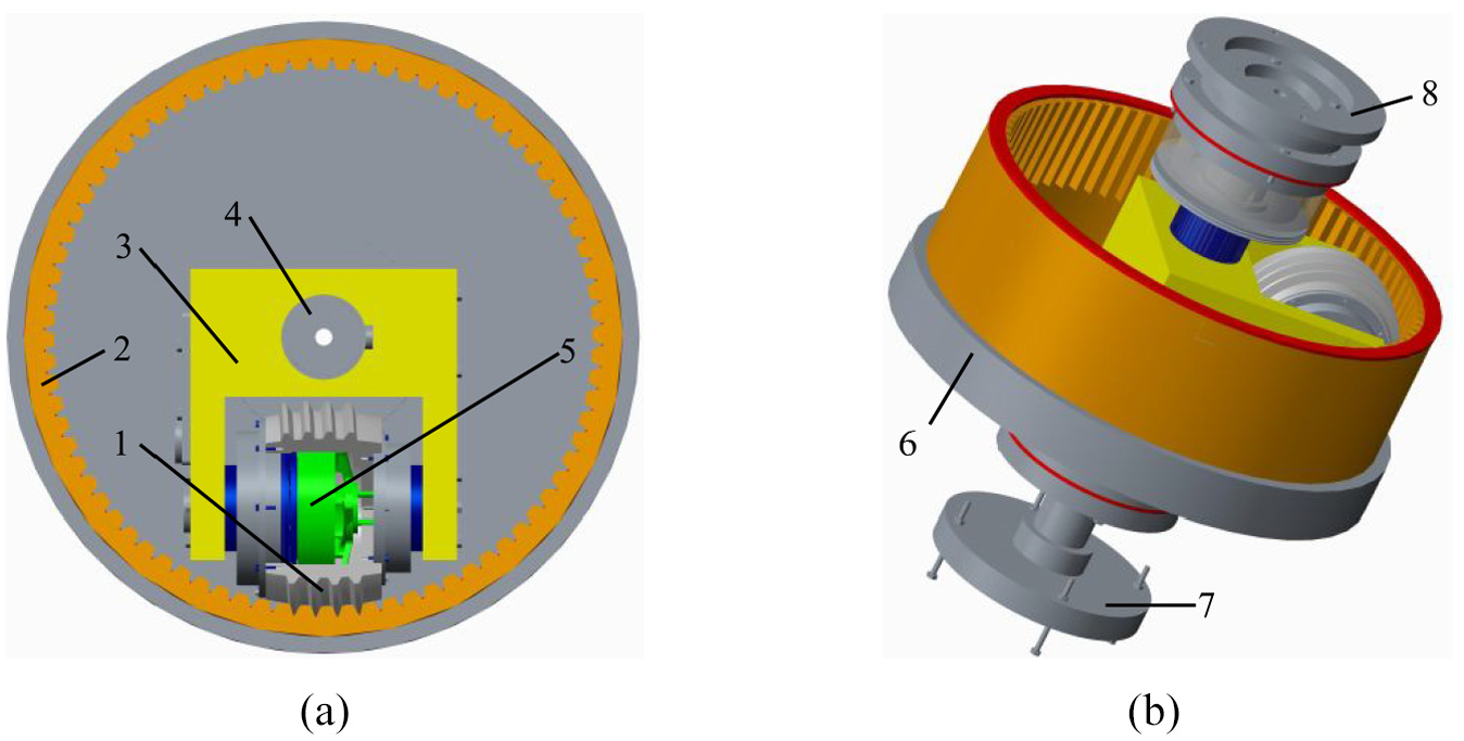
Inner worm-gear plane enveloping drum worm drive reducer. 1. Worm; 2. Worm-gear; 3. Bracket; 4. Pillar; 5. Motor; 6. Worm-gear seat; 7. Fixed flange; 8. Output flange: (a) internal structure, and (b) whole structure.
In the area of the internal meshing worm drive, Chen et al.11,12 proposed one kind of internal meshing worm pair adopting non-orthogonal worm drive with complicated gearbox, yet utilizing an external motor realizes its driving. It is necessary to have the function of backlash adjustment for backlash and friction compensation13–16 in the field of high-precision reducer to realize small even zero clearance in order to guarantee high-precision transmission for precision devices such as robot joints. Qiu et al. 17 and Chen et al. 18 investigated the gradual-change tooth thickness planar worm gear drive and the variable tooth thickness involute gear enveloping hourglass worm drive, respectively. Both of above types adopt the variable tooth thickness worm-gear to realize backlash adjustment by adjusting relative position between the worm and worm-gear in axial direction of the worm-gear. The novel reducer realizes backlash adjustment by above method and it is characteristic with smaller volume, more compact structure, high-precision transmission, etc. due to the integrated structure.
Finite element method and numerical analysis are widely utilized to perform the contact and mechanics analyses of the worm drive. By this way, Rao 19 and Zheng et al. 20 realized the failure and contact analysis of worm drive, respectively. In the field of manufacture, using the modified CNC grinder based on the machining principle of virtual center distance was to conduct the processing of the plane enveloping worm effectively.11,21 Base on that, this paper focuses on the investigation of the drum worm pair of the novel reducer in such areas including design, analysis and manufacture.
Meshing theory
The meshing theory of the inner worm-gear plane enveloping drum worm pair is divided into two parts: macro and micro. The former is the basis for constructing the worm pair and the necessary condition for the design of the worm pair. The latter is the theoretical reference for evaluating the meshing properties of the worm pair, which is mainly used to analyze the meshing properties of the worm pair for optimization. In this study, the macro meshing theory of the worm pair is established for the process of design-analysis.
The tooth-surfaces on both sides of a worm-gear tooth are defined as generating plane A (abbreviated as plane A) and generating plane B (abbreviated as plane B), respectively. The conjugate surface is the plane A yet the non-conjugate surface is the plane B during the worm pair rotates forward (Figure 2), and the opposite is true with the reverse rotation. The planes A and B are tangent to the same base-cone, here the corresponding inclination angles meet
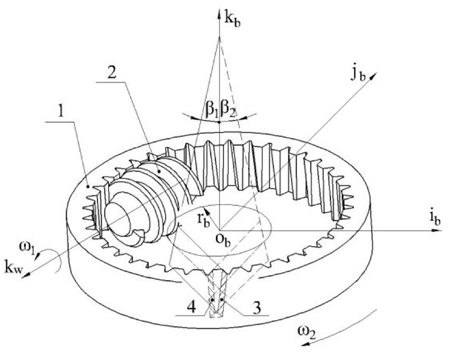
Inner worm-gear plane enveloping drum worm pair. 1. Worm-gear; 2. Drum worm; 3. Generating plane A; 4. Generating plane B.
The tooth-surface of the drum worm with a right-handed thread is formed by a series of worm-gear planar tooth-surfaces according to conjugate meshing motion. The coordinate frame systems of the forward and reverse rotations are shown in Figure 3(a) and (b), respectively. In Figure 3, the distance between origin points of fixed coordinate frames

Coordinate frame systems: (a) forward rotation, and (b) reverse rotation.
According to the gear meshing theory,
24
meshing functions of the forward and reverse rotations of the inner worm-gear plane enveloping drum worm drive are established in equations (1) and (2), respectively. The meshing point P appears on the plane A, the functions of meshing


Design and manufacture process
The systematic design and manufacture process of the inner worm-gear plane enveloping drum worm pair is proposed in this part. Referring to design method of the plane enveloping hourglass worm pair, the drum worm pair is designed because they both belong to the planar worm-gear pair. According to meshing theory, classical mechanics, finite element method and machining principle of virtual center distance, etc., the flowchart of design and manufacture of the drum worm pair is proposed as shown in Figure 4.

Flowchart of design and manufacture.
Design parameters
Design conditions
The inner worm-gear plane enveloping drum worm drive reducer is designed from inside to outside due to that it is driven by the known external rotor motor installed in the hollow worm. In the progress of design, the following conditions should be considered.
Motor parameters
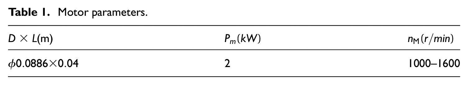
U10PLUS KV32 motor manufactured by T-MOTOR is selected, whose parameters are shown in Table 1, here D and L represent the diameter and length, as well as
Motor parameters.
Worm rotation speed n1 (r/min), input power P1(kW), transmission ratio i1
The transmission ratio of the worm pair is designed as
Work conditions
It is assumed that work time is no more than 8 h a day with starting no more than two times per hour, the work load is 100% with stable load, and the start load does not exceed 125% of the work load.
Machining accuracy and tooth-surface roughness of the worm pair
The machining accuracy of the worm pair needs to reach grade 6 in order to guarantee the tooth-surface roughness below
Material and heat treatment of the worm pair
In order to make the hardness reach HRC43∼55, the tooth-surface of the worm made from 40Cr steel is processed by grinding and then subjected to nitriding. The worm-gear made from ZQSn10-1 (tin bronze) is manufactured by sand casting and the hardness of its tooth-surface reaches HB80∼100. Based on above materials, the recommended range of the relative sliding speed
Design parameters of the worm pair
As shown in Figure 5, compared with the hourglass worm pair on the same scale, the drum worm pair is characterized with smaller size and more compact structure due to the internal meshing transmission. The “crown” of the drum worm corresponds to the “throat” of the hourglass worm, and the distance

2 types plane enveloping worm pair. 1. Mid-plane of the worm; 2. Mid-plane of the worm-gear: (a) drum worm pair, and (b) hourglass worm pair.
Referring to the design method and parameters of the plane enveloping hourglass worm pair
25
and combining with the function fitting method, the relevant design parameters of the right-handed inner worm-gear plane enveloping drum worm pair are determined as shown in Table 2.
Parameters of the drum worm pair.

Mechanical properties analysis
Bending stress and deflection of the worm
Force analysis of the worm
The force analysis of the worm in the case of forward rotation is shown in Figure 6(a) because the forces are same no matter whether the worm pair rotates forward or reverse.


Force analysis and deflection of the worm: (a) force analysis, and (b) schematic diagram of deflection deformation.
Bending stress of the worm
According to the work conditions, the bending stress

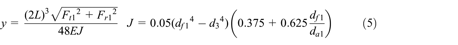
Deflection of the worm
Considering that the deflection deformation of the worm on its mid-plane is mainly affected by the tangential force
Shear stress and bending stress of the worm-gear teeth
Shear stress of the worm-gear teeth
As shown in Figure 7(a),
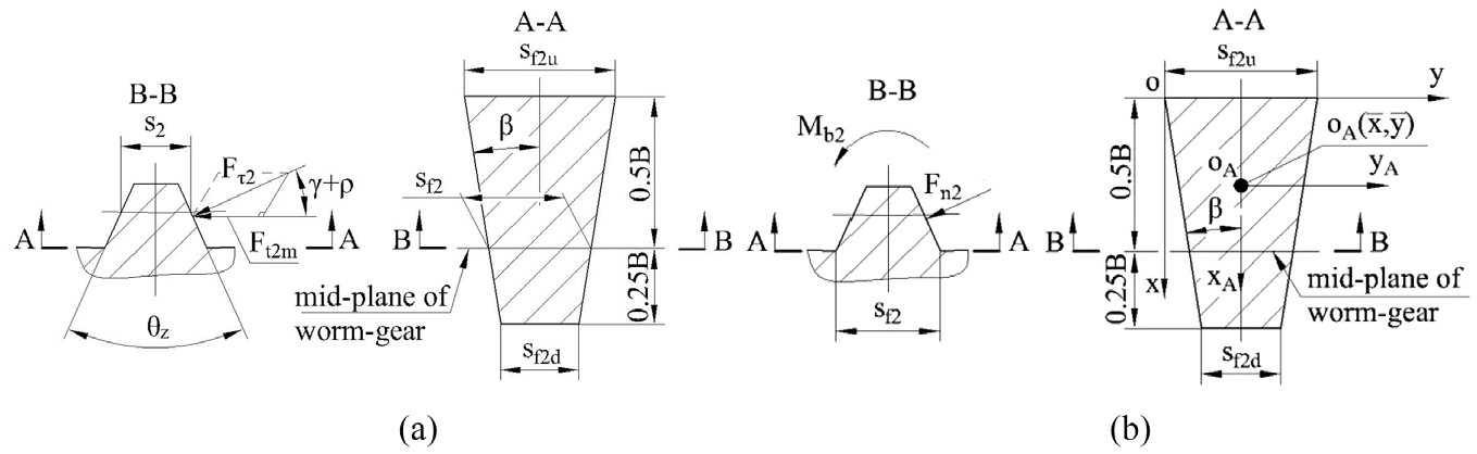
Shear stress and bending stress of worm-gear teeth: (a) shear stress of worm-gear teeth, and (b) bending stress of worm-gear teeth.
Meanwhile

Substituting parameters of Table 2 into equation (6), the shear stress
Bending stress of worm-gear teeth
As shown in Figure 7(b),
Let


Contact properties analysis
Finite element setting
The worm tooth-surfaces are obtained by
The contact stress of the 3D models of the worm pair is analyzed by the function, static structure analysis, in software WORKBENCH. The material library of the worm pair is established according to the material parameters as shown in Table 3, here E,
Material parameters of the worm pair.

According to Tables 1 and 2, the maximum torque
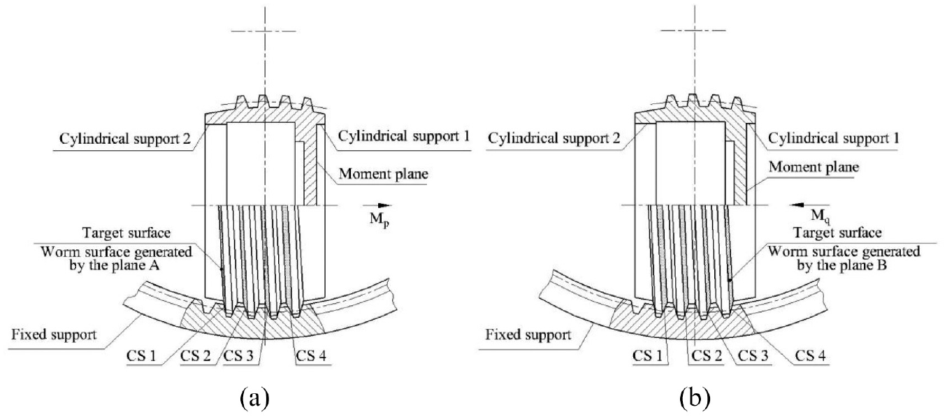
Finite-element setting of the worm pair: (a) forward rotation, and (b) reverse rotation.
The spiral teeth of the worm could simultaneously mesh with four planar teeth of the worm-gear during the conjugation because of
Finite element analysis
As shown in Figure 9, the contact areas of the forward and reverse rotations of the worm pair are analyzed by the contact tool of WORKBENCH, respectively. The contact areas diffuse in the direction of the increasing and decreasing tooth thickness of the worm-gear corresponding to the forward and reverse rotations, respectively. Regardless of forward or reverse rotation, the largest contact areas both appear at engaging-out position.

Contact areas of the worm pair. 1. Engaging-in position; 2. Engaging-out position; 3. Direction of increasing tooth thickness: (a) forward rotation, and (b) reverse rotation.
The contact stress of the worm-gear tooth-surfaces needs to be analyzed due to lower hardness of the material adopted by the worm-gear. The contact stresses are mainly distributed on the planes A and B respectively corresponding to the forward (Figure 10(a)) and reverse (Figure 10(b)) rotations of the worm pair. The maximum contact stresses of the forward and reverse rotation are marked as

Contact stress analysis of the worm-gear tooth-surface: (a) forward rotation, and (b) reverse rotation.
The allowable value of the contact stress of the worm-gear tooth-surfaces is represented as
Prototype manufacturing
Processing parameters
Base on that, the mechanical and contact properties of the drum worm pair satisfy the work requirements through above analyses, the prototype of the novel reducer with the drum worm pair is manufactured. According to the design parameters (Table 2), the processing parameters of the right-handed worm pair are shown in Table 4, where
Processing parameters.

Processing of the worm tooth-surface
The worm tooth-surface is processed according to the processing parameters in Table 4, here
According to Table 4 and Figure 11, the worm tooth-surfaces are ground by the modified 4-axis linkage CNC grinder based on the machining principle of virtual center distance. The processing is completed by the 4-axis linkage of X-axis, Y-axis, Z-axis, and A-axis, where the origin

Processing of worm tooth-surface. 1. Worm blank; 2. Plane grinding wheel: (a) processing principle, and (b) modified 4-axis linkage CNC grinder.
Prototype assembly
The processed worm tooth-surface is shown in Figure 12(a), and the worm-gear is processed by the wire cutting. Then according to Figure 1, the industrial prototype of the inner worm-gear plane enveloping drum worm drive reducer is assembled and its internal structure is shown in Figure 12(b).

Manufacture of prototype: (a) tooth-surface of drum worm, (b) internal components, (c) worm-gear seats (gearboxes), and (d) novel joint reducer. 1. Output flange; 2. Worm-gear seat; 3. Fixed flange.
In Figure 12(d), the outward appearance of the novel joint reducer is presented with overall size including length 436 mm and diameter 370 mm. In the reducer, the gearbox is simplified as the worm-gear seat for the support of the worm-gear and outputs rotation by the output flange fixed to it, as well as the fixed flange rigidly connected to the pillar is used to fix the reducer. The worm-gear seats with outer diameter 370 mm are displayed in Figure 12(c), they are made from 6061 aluminum in order to decrease their weights. However, the size of the reducer is large which is mainly affected by the motor’s size due to adoption of the design method from inside to outside. Therefore, the follow-up investigation of a special motor with smaller volume and larger power could help reduce the size of the reducer to make it more compact.
Conclusion
The design and manufacture of the novel worm pair were investigated in this paper and conclusions are shown as follows:
The novel joint reducer with integrated structure of drive, transmission and support was designed and manufactured for the first time. The reducer adopts a new type internal meshing plane enveloping worm pair consisting of a planar internal worm-gear and an orthogonal right-handed single-thread drum worm, and is driven by a built-in external rotor motor installed in the hollow worm. In addition, the structures of support components are simple and easy to process without the need of complicated gearboxes. Therefore the novel reducer is characteristic with compact structure, high transmission and manufacture accuracy, easy processing, backlash adjustment, and easy sealing, etc.
The systematic design and manufacture process of the novel worm pair was proposed, including meshing theory, structure design, properties analysis and prototype manufacturing.
The meshing theory of the novel worm pair was established according to the gear meshing theory and the design method of plane enveloping hourglass worm pair, as well as the design parameters of the worm pair were determined combined with the function fitting method.
In the terms of the mechanical and contact properties analysis, the bending stress and deflection of the worm, the shear and bending stress of the worm-gear teeth were analyzed by classical mechanics, as well as the contact stress of the worm-gear and the contact area of the worm pair were analyzed by WORKBENCH according to the finite element method. Through above analyses, the mechanical and contact properties of the worm pair were guaranteed to satisfy the work requirements.
The processing method of the drum worm was proposed where the drum worm was processed by the modified 4-axis linkage CNC grinder based on the machining principle of the virtual center distance, and the industrial prototype of the novel joint reducer was manufactured.
Footnotes
Appendix
Declaration of conflicting interests
The author(s) declared no potential conflicts of interest with respect to the research, authorship, and/or publication of this article.
Funding
The author(s) disclosed receipt of the following financial support for the research, authorship, and/or publication of this article: This work was supported by the National Natural Science Foundation of China (Grant No. 51575456).