
Abstract
The spray characteristics of the pressure swirl nozzle are experimentally studied using particle dynamics analysis (PDA) and high-speed photography system in this paper, specifically focusing on the dependence of geometrical dimensions of orifice on the spray SMD, velocity magnitude and droplet distribution, and the spray cone angle. It is indicated that the increase of orifice diameter makes the initial swirling velocity lower and the spray liquid film thicker. When the spray cone is fully expanded, the flow rate of 900 μm orifice diameter nozzle increases by 30–40% and the SMD of 900 μm orifice diameter nozzle increases by 8.5% compared with that of 700 μm orifice diameter nozzle. According to the experimental conditions, the relationship between Re and spray angle was calculated as θ = 29.97*Re0.087, ignoring the factors that had little influence on spray angle. The decrease of the orifice length makes the distance of gas-medium shearing action shorten so that thinner oil film near wall cannot be formed by the extrusion of air core, leading to the swirling intensity reducing and the suction effect weakened. The spray cone angle of the 450 μm orifice length atomizer is about 5° smaller than the nozzle of 500 μm orifice length, and more small SMD droplets are not sucked, resulting in the distribution range of spray SMD declining.
Introduction
Pressure swirl nozzle is widely adopted in various kinds of power equipment such as rocket engine, aircraft engine and gas turbine due to its simple structure, good atomization performance, and low cost. 1 Sauter mean diameter (SMD), droplet velocity and spray cone angle are the key parameters of the pressure swirl nozzle which reflects the quality of droplet generation, transport and distribution in the combustion chamber respectively. The combustion efficiency can be improved by controlling these parameters to reduce the emissions of carbon compounds.2–6
The thickness of the liquid film formed by the spray medium can affect the spray cone angle and the droplet size, while the formation process of the liquid film mainly occurs in the orifice. The geometric dimensions of the orifice will significantly affect atomization process, in which spray medium is extruded by the air core in the orifice and then forms a liquid film near the wall. Liu et al.7,8 found that shorter orifice makes liquid film thickness decrease nonlinearly, and the longer orifice produces thicker liquid film. The growth of the orifice length makes the spray cone angle decline and the growth of the orifice diameter makes the spray cone angle increase. When the length to diameter ratio of the orifice increases, the spray cone angle decreases, with the liquid film thickness and the spray SMD increasing. Yang 9 designed orifices with different length to diameter ratios of 0.3, 9.75, 10.35, 11.05, and 11.85 respectively, and found that the spray cone angle decreases when the ratio changes from 9.75 to 11.05. Rashad et al. 10 made experiments under pressure of 0.8 MPa and 1.2 MPa respectively, and found that when the geometric ratio of orifice increases from 0.81 to 2.69, the spray SMD changes a little bit. However, when the geometric ratio is less than 1.44, increasing the orifice length can promote the growth of air core, and get the largest spray cone angle. 11 When the ratio is large than 1.44, with the increasing of the orifice length, the energy loss caused by friction increases and the spray cone angle decreases. Moon et al. 12 found that with the reduction of the orifice length, the axial and radial velocity of spray cone near the orifice grows up, which results in the decrease of the symmetry spray cone and the increase of the droplet velocity along the axis and the turbulence intensity gradient. The diminishing of orifice length reduces the spray penetration distance and the droplet SMD, but the spray cone angle gets larger. Datta et al. 13 simulated the influence of orifice geometry on flow coefficient and spray cone angle, showing that the growth of orifice diameter declines the orifice discharge coefficient and increases the spray cone angle. Marchione et al. 14 used PDA system and found that the velocity and SMD distribution is axially symmetric.
Compared with the centrifugal nozzle, the size of the swirl nozzle is usually smaller. Previous researchers mainly focus on the centrifugal orifice, while the existing studies on the swirl orifice are relatively limited. So it is not sure whether the former mechanism is applicable to the latter or not. The length to diameter ratio, which is frequently used in the study of centrifugal orifices, is determined by the diameter and length of the straight section. However existing researches usually analyze the influence of one variable without comprehensive comparison. In order to further investigating the influence of swirl orifice diameter and depth on spray atomization characteristics, in this paper, the spray flow rate, spray SMD, droplet axial velocity and spray cone angle are experimentally studied under different length to diameter ratios or under the same length to diameter ratio with varied combination of the diameter and depth of orifice. The axial velocity of SMD and droplet are compared and analyzed, and the influences of orifice geometry on SMD, droplet axial velocity and spray cone angle are further studied.
Experimental setup
The structure of the experimental system is shown in Figure 1, which consists of an experimental nozzle, Particle dynamics analysis system (PDA), high-speed photography system, constant flow pump, pipeline, and spray shield. The SMD and droplet velocity are measured by PDA, and the atomization cone angles of orifices with different geometric characteristics are measured by high-speed photography system.
Layout of the experiment system: (a) PDA system and (b) High-speed photographic system.
The 3-Dimensions Fiber PDA (Dantec) is used, and the spray parameters are measured and analyzed based on BSA Flow Software v5.20 software. Argon laser (Innova70C) produces a laser beam which is split by Transmitter into its individual color components (476.5 nm, 488.0 nm, 514.5 nm) with each color divided into three beams. The measurement accuracy of droplet diameter and velocity components is 0.01 mm and 0.01 m/s. The scattering angle was 73.5°, which is Brewster’s angle. The number of droplets collected at the condition of its measurement point as 10,000 or the acquisition time as 30 s so as to reduce the data instability. The test will be finished if either of the conditions is satisfied. The scattering model is a refraction model. The focal length of the receiver is 500 mm and the sensitivity is 1200 V. High-speed digital microscopy system (VW-9000, Keyence) and lens (VH-Z20R, Keyence) are used to save 150 frames per second. The shutter speed is 125 μs and the image resolution is 640 × 480. The constant flow pump (LP0110, Shanghai Sanwei) offers the Stable injection pressure conditions to the pipeline. The spray medium used in the experiment is water. The pressure gauge (HSFN-60, Kechuang) is used to measure the pressure of liquid in the spray process, and its range 0–1.6 MPa. By observing the reading of the pressure gauge, the effect of pulsation of the pump and the test platform on the spray can be excluded.
The structure of the experimental nozzle along with various components is shown in Figures 2 and 3. The nozzle consists of inlet section, acceleration section, swirling section and orifice. The spray medium enters into the nozzle from the inlet section, and which is accelerated by the reduction of the circulation area in the acceleration section. Then it is further accelerated by the swirl section until it reaches adequate circumferential velocity, and finally ejections from the orifice are incurred. Water is used as spray medium and the outlet condition is atmosphere.

Objects of experimental atomizer: (a) Swirl core, (b) Shell A, (c) Shell B, and (d) Shell C.
Flow direction of spray medium of experimental atomizer.
In order to study the influence of the diameter and length of the equal straight section of the nozzle on the atomization effect, following three sizes of the nozzle have been selected. Spray experiments are carried out with three nozzle shells and swirling core respectively. The length to diameter ratio of nozzle B is the same as nozzle C while the orifice length of nozzle A is the same as that of nozzle B. The orifice length of the nozzle is consistent with the boundary on the inner wall of the hole. The size parameters of the swirling core of the experimental nozzle are shown in Table 1, and the size parameters of the nozzle shell in Table 2.
Size parameters of swirling core.

Size parameters of nozzle shell.

Results and discussion
The influence of orifice geometric on spray SMD
In order to study the influence of pressure on spray SMD of nozzle A, B, and C, the measuring point is set at 50 mm below orifice, and the relationship curves of spray SMD of nozzle A, B, and C with pressures are obtained as shown in Figure 4. As the pressure increases from 0.08 MPa to 0.32 MPa, the SMDs of nozzle A, B, and C decrease to 103.1 μm, 67.5 μm, and 91.1 μm, and the percentage of the decrease were 70.7%, 82.6%, and 74.2%, respectively. That is because that the swirling effect of spray medium is enhanced with increasing pressure and the diameter of the center air core, leading to the thickness of the liquid film decreasing, reaching easily to breakups. The increase of pressure promotes the spray velocity of the spray medium, which in turn enhances the interaction of spray medium and ambient air, also reduces the droplet SMD. When the pressure exceeds 0.32 MPa, the SMDs of nozzle A, B, and C decrease slightly, and the SMD of nozzle A, B, and C at the measuring point keeps stable at 44 μm, 34 μm, and 48 μm respectively, which satisfies the breaking mechanism of droplets in stable air. 15

Curves of pressure versus SMD.
The influence of orifice geometric on flow characteristics
The relationships between flow rates of the nozzle A, B, and C with the pressure are shown in Figure 5. The flow rates can be read on the screen of the constant flow pump. In the range of 0.08 MPa to 0.60 MPa, the flow of nozzle A, B, and C are proportional to the pressure. The flow rate of the nozzle A increases from 120 ml/min to 300 ml/min with a growth rate of 150%. The flow rate of the nozzle B increases from 155 ml/min to 418 ml/min with a growth rate of 169.7%. The flow rate of the nozzle C increases from 135 ml/min to 347 ml/min with a growth rate of 157%. Under the same pressure condition, the flow rate of nozzle B is 29.2–39.3% higher than that of nozzle A, and the flow rate increment is 41.9% higher than that of nozzle A. The flow rate of nozzle C is 12.5–15.6% higher than that of nozzle A, and the flow rate increment is 17.8% higher than that of nozzle A. The diameters of nozzle A, C, and B are 700 μm, 800 μm, and 900 μm, respectively. The results show that the flow characteristics and the flow rate of nozzle B with the largest diameter are the best, and that of nozzle A with the smallest diameter is the worst. Under the same pressure condition, increasing the orifice diameter will get larger effective circulation area and improve the flow characteristics.

Curves of pressure versus flow rate.
The influence of orifice geometric on the distribution of axial and radial velocity
In order to study the radial distribution of spray droplet velocity of nozzle A and B, the distances of radial distribution measurement section are set at 20 mm, 40 mm, 60 mm, and 80 mm respectively below orifice and the measuring points are selected in every 5 mm(Figure 1).
The radial distribution curves of droplet axial velocity of nozzle A, B, and C, shown in Figure 6, are similar to the results in literatures.16–18 After the liquid film is broken, large droplet is formed in the spray periphery and small droplet is formed in the spray center on the 20 mm cross section near the orifice. The kinetic energy of the droplets at the spray periphery is large. Therefore, the axial velocity presents a bimodal distribution. The radial distribution range is less than 20 mm from the axis. As the distance varies from 20 mm to 60 mm below the orifice, the spray expands continuously, while the radial distribution range of the droplet axial velocity extends to be nearly 40 mm. The contact area between the spray medium and the ambient air near spray cone increases, and the droplet kinetic energy decreases in all directions due to the friction effect. The radial and tangential velocities of spray medium are smaller near the axis of the spray cone, so the kinetic energy loss mainly exists in the axial direction. Therefore, the velocity attenuation along the axial direction near the axis of the spray cone is very small, and gradually achieves the peak value with the increase of distance. In the range of 60–80 mm from the orifice, the axial velocity of droplets decreases slightly, and the increment of distribution area is small.
Axial velocity distribution in radial direction at the same pressure: (a) Nozzle A,0.32 MPa, (b) Nozzle A,0.60 MPa, (c) Nozzle B, 0.32 MPa, (d) Nozzle B, 0.60 MPa, (e) Nozzle C, 0.32 MPa, (f) Nozzle C, 0.60 MPa.
The radial distributions of droplet radial velocities of nozzle A, B, and C are shown in Figure 7. The radial velocity of droplet in each measuring point is less than 8 m/s, which is much smaller than the axial velocity. The radial position of the positive and negative peak value coincides with the peak value position of the axial velocity. As the distance between the measuring section and the orifice increases from 20 mm to 60 mm and the spray cone quickly expands, the peak values of positive and negative radial velocity decrease rapidly by about 50%. In the further downstream area of the spray, the radial distribution of the spray cone does not have any significant enlarge, and the radial velocity attenuation of the droplet slows down.
Radial velocity distribution in radial direction at the same pressure: (a) Nozzle A, 0.32 MPa, (b) Nozzle A,0.60 MPa, (c) Nozzle B, 0.32 MPa, (d) Nozzle B, 0.60 MPa, (e) Nozzle C, 0.32 MPa, and (f) Nozzle C, 0.60 MPa.
When the pressure is 0.32 MPa, the spray cones of nozzle A, B, and C are generally expanded. The maximum axial velocities are 11.54 m/s, 12.36 m/s, and 12.47 m/s respectively, and the maximum radial velocity differences are 9.96 m/s, 12.01 m/s, and 7.79 m/s respectively. There are two peaks at 20 mm downstream the orifice and r = 15 mm in Figure 5. That is because the maximum radial velocity appears along the expansion of liquid film. When the pressure is low, the spray cone of nozzle A is not fully developed and the distribution of spray is uneven. The nozzle A, B and C reach the rated pressure at 0.60 MPa pressure, and the maximum axial velocities are 15.29 m/s, 14.79 m/s, and 15.22 m/s respectively, and the maximum radial velocities are 15.07 m/s, 12.86 m/s, and 13.32 m/s separately. The orifice diameters of nozzle B and C are 800 μm and 900 μm respectively, larger than that of nozzle A. The orifice with larger diameter has larger circulation area, which results in small initial injection velocity in all directions. The axial velocity of nozzle C is large, which is close to that of nozzle A. The radial velocity range is small, which is close to the nozzle B, and the spray distribution area is narrow. The length to diameter ratios of nozzle B and C are 0.56, which is smaller than that of nozzle A. The orifice length of nozzle C is 450 μm, less than that of nozzle A and B. Shorter orifice length makes the shearing distance between the air core and the spray medium shorter, and the spray medium is not fully extruded by the air core to form enough swirling intensity before spray out the orifice, which makes the spray cone angle of the nozzle C is smaller than that of the nozzle A and B under the same pressure from 7° to 9°, and the spray expansion degree is low. Although the shorter orifice length decreases the kinetic energy loss due to friction, but the swirling intensity is also weakened.
The influence of orifice geometric on the distribution of SMD
In order to study the radial distribution of SMD for nozzle A, B, and C, the distances of radial distribution measurement section are 20 mm, 40 mm, 60 mm, and 80 mm respectively below orifice and the measuring points are selected in every 5 mm.
As shown in Figure 8, the radial distribution of SMD in each cross section is bimodal, and the radial position of maximum value is consistent with that of axial velocity. Similar to Section 2.3 and 2.4, large droplets have greater kinetic energy and distribute in outer part of the spray cone. With the development of the spray cone, the spray reflux cone appears, and small droplets are distributed in the center of the spray cone. The SMD will decrease as the pressure increasing from 0.32 MPa to 0.60 MPa. The swirl effect of nozzle B is the strongest, resulting in the largest numerical range of droplet SMD. The nozzles C have the weakest cyclone effect, leading to the smallest SMD value. The distribution characteristics are basically the same as the literature. 19
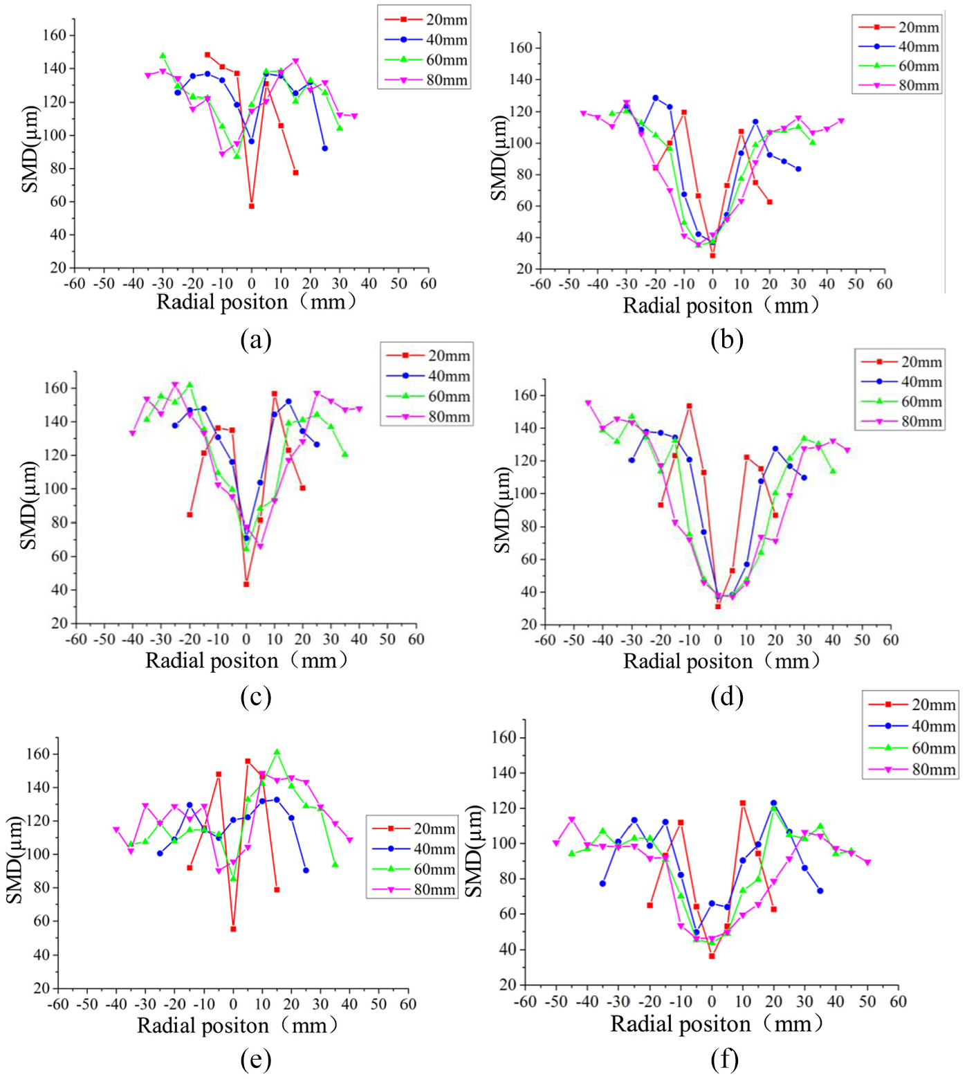
SMD distribution in radial direction at the same pressure: (a) Nozzle A, 0.32 MPa, (b) Nozzle A, 0.60 MPa, (c) Nozzle B, 0.32 MPa, (d) Nozzle B, 0.60 MPa, (e) Nozzle C, 0.32 MPa, and (f) Nozzle C, 0.60 MPa.
From Figure 9, it is known that the SMDs of nozzle A, B, and C generally decrease as the distance below the orifice increase. When the pressure is 0.32 MPa, if the distance changes from 10 mm to 100 mm below the orifice, the average SMD of nozzle A will decrease from 172.6 μm to 119.8 μm with a reduction of 30.6%. The average SMD of nozzle B will decrease from 165.7 μm to 110.7 μm with a reduction of 33.2%. The average SMD of nozzle C will decrease from 204 μm to 114.1 μm with a reduction of 44.1%. The nozzle B will reach the rated spray cone angle 66.92° at the pressure of 0.32 MPa, and the spray cone has basically been expended. Compared with nozzle B, the spray cones of nozzle A and C are expended inadequately which are much similar to that of semi bubble, and the spray cone angles are smaller by 4.3% and 7.7% respectively. The radial velocities of A are 6.6% and 17.1% smaller than those of the nozzle B respectively. The radial velocity of the nozzle C is 35.1% smaller than that of the nozzle B with the same length to diameter ratio, and the intensity of the interaction with the ambient air is lower. In conclusion, the average SMD of nozzle B is 5–10 μm smaller than that of nozzle A and C at 0.32 MPa pressure. When the pressure is 0.60 MPa, the spray of A, B and C are all fully expanded and reach stable state. The average SMD of the nozzle A reduces from 127.1 μm to 68.5 μm with a reduction of 46.1%. The average SMD of the nozzle B decreases from 123.9 μm to 75.5 μm with the reduction of 39.1%. The nozzle C with the same length to diameter ratio reduces from 89.7 μm to 70.1 μm with the reduction of 20.8%. The axial velocity of nozzle B is 3.3% and 2.8% lower than that of nozzle A and C, and the radial velocity is 14.7% and 3.5% lower than that of nozzle A and C, respectively. The average SMD of each measuring cross section of nozzle B is slightly larger than that of nozzle A and C under the condition of pressure 0.60 MPa.

Average SMD of each sections of spray cone.
The influence of orifice geometric on the spray cone angle
The spray cone angle reflects the distribution range and topology of spray cone. It can directly show the atomization effect of the nozzle, and larger spray angles result in larger attachment areas with the ambient air. In this paper, a method commonly used in engineering is used to express atomization cone angle. Two lines tangent to the liquid film are drawn from two points at the nozzle outlet. The included angle between the two lines is the spray cone angle. The spray cone angle under different pressures is shown in Figure 10.

Diagram of the spray cone angle.
The angle between the gas-liquid boundaries near the orifice is the spray cone angle. The medium is formed by coupling turbulence interaction and pressure in the spray medium. To get the gas-liquid boundary, the photos taken by the high-speed photography system are binarized using Matlab software, and the threshold intensity is 50%. Then the spray cone angles are measured as shown in Figure 9. When the pressure ranges vary from 0.08 MPa to 0.14 MPa, the liquid film shrinks into bubbles, because the pressure cannot overcome the surface tension of the spray medium. When the pressure is higher than 0.14 MPa, the spray medium will overcome the surface tension due to the increase of the pressure, and bubbles will burst with the spray cone angle gradually expanded. When the pressure is higher than the critical value, the frictional loss of the spray medium energy in the nozzle will hinder further increasing of swirling intensity, and the spray cone angle tends to be stable. The pressure critical value of A, B, and C nozzles are 0.325 MPa, 0.3 MPa, and 0.275 MPa respectively.
Figure 11 shows the spray cone angles of nozzle A, B and C varying with pressure. As the pressure increases from 0.14 MPa to 0.50 MPa, the spray cone angle of the nozzle A increases from 61.14° to the maximum degree of 65.07° with an increase of 6.4%, reaching to its stability around 64° in the end. As the pressure increases from 0.14 MPa to 0.50 MPa, the spray cone angle of the orifice C increases from 55.89° to the maximum degree of 61.93° with an increase of 10.8%, and keeps stable at about 61° in the end. Compared with the nozzle A and C, the nozzle B can fully expand the spray cone under the condition of 0.14 MPa. When the pressure is low, the spray cones of nozzle A and orifice C are semi-bubble, and will be fully developed the pressures are higher than 0.22 MPa and 0.30 MPa respectively. The orifice diameter of the nozzle B is larger than that of the nozzle A, and the resistance of the spray medium is smaller. It is easier to generate stable and strong swirling flow. The insufficient shearing action between the spray medium and the air core of nozzle C, which has the same length to diameter ratio with the nozzle B, results in the weaker swirling intensity due to the short orifice length, so the expansion effect of the spray is worse than those with larger length to diameter ratios and small orifice diameters. This is basically consistent with the results of literatures.20,21
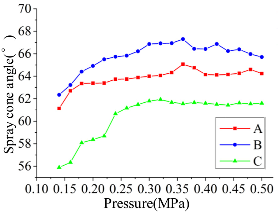
Curves of pressure versus spray cone angle.
All parameters, including equal straight section of nozzle, geometric size of swirling flow, surface tension, viscosity, density of working medium and air density, have influences on atomization cone angle. According to experimental conditions, factors that have little influence on atomization cone Angle are ignored, and the relation of Re and spray cone angle is fitted based on that of Zhang et al. 22 as equation (1).

θ is the spray cone angle and Re = ρVd/μ. The changes of Re data and spray cone angle of nozzle A and B under different injection pressures can be obtained from Figure 12. Compared with the conclusion of Zhang et al., it is found that the spray cone angle is improved because of the differences of the nozzle geometry. Liu et al. 23 compared the spray angle of the nozzle with different geometric parameters, and found that the spray angle decreases with the increase of the nozzle length. Besides, Datta et al. 24 found that the spray cone angle increases with the increasing convergent angle of the swirl chamber. Comparing with nozzles in literature, 22 the length of straight section is smaller and the convergence angle of swirling flow of the nozzle A and B used in this experiment is larger, which will increase the spray cone angle under the same Re condition.
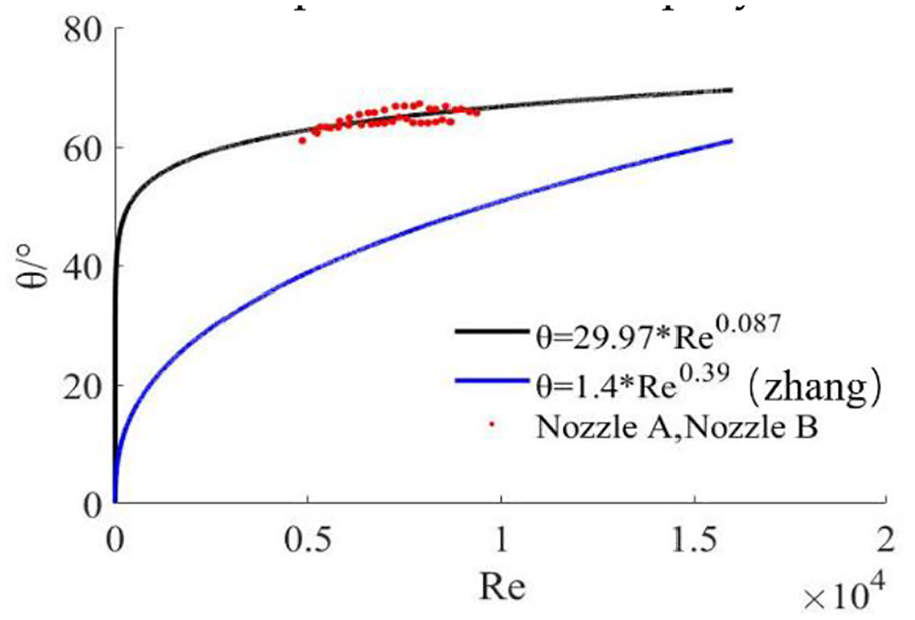
The comparison between experiment data and fitting value.
Conclusion
The increase of orifice diameter makes it easier to get stable swirling flow, and the spray cone can be expanded under low pressure. Larger orifice diameter has larger flow rate, which results in smaller initial circumferential velocity and thicker liquid film. Due to the short interaction distance between orifice and air core, the spray medium can’t get fully squeezed to form a thin fluid form near the wall. The short interaction distance also makes the intensity of the swirling effect weak, results in small spray cone angle. According to experimental conditions, factors that have little influence on atomization cone Angle are ignored, and the relation of Re and spray cone angle is fitted.
The reduction of orifice length will decrease the friction loss of spray medium slightly, but it also makes the swirling intensity of the spray medium decrease, weakening the suction effect of the swirling center reflux zone, while droplets with small SMD keep the original moving direction, incurring smaller range of SMD distribution. Increasing the orifice diameter will reduce the initial circumferential velocity of the spray, but also reduces the resistance. It makes the spray cone expand under small pressure, and has a larger area of interaction with the ambient air, reaching a smaller SMD. For the fully developed spray cone, smaller orifice diameter will get larger initial circumferential velocity, stronger swirling intensity and smallest spray SMD.
Footnotes
Acknowledgements
The authors are especially grateful to all those who collaborated in this research project, specially to Dr. Longxiang Zhang for giving the suggestion to this article
Author Contributions
Conceptualization, Huilong Zheng and Zhaomiao Liu; Formal Analysis, Huikong Zheng, Kaifeng Wang and Jiayuan Lin; Funding acquisition, Zhaomiao Liu; Investigation, Huilong Zheng; Methodology, Huilong Zheng; Resources, Zhaomiao Liu; Writing—original draft, Huilong Zheng and Kaifeng Wang; Writing—review &editing, Huilong Zheng and Jiayuan Lin.
Declaration of conflicting interests
The author(s) declared no potential conflicts of interest with respect to the research, authorship, and/or publication of this article.
Funding
The author(s) disclosed receipt of the following financial support for the research, authorship, and/or publication of this article: This research was funded by the Aeronautical Science Foundation of China, grant number 20140375002, 20150375001.