
Abstract
To improve the intershaft seal performance of the dual-rotor turbofan engine and extend the life of the intershaft seal, a compliant cylindrical aerodynamic intershaft seal structure is proposed, which avoids the problem of leakage increase after tooth wear of intershaft labyrinth seal. According to the proposed seal structure, the force condition of the floating seal ring is analyzed, and an aeroelastic coupling method for the floating seal ring eccentricity is presented. And the leakage characteristics, with different seal structures and operating conditions are calculated and compared when the two rotors are under homodromy/counter-rotating condition. The results show that, for the dual-rotor cylindrical hydrodynamic gas film seal, the hydrodynamic effect under homodromy condition is enhanced greatly while the hydrodynamic effect is significantly weakened under counter-rotating condition; the rotational direction of rotors, seal width, rotor circular precession eccentricity, rotational speed and rotor radius all have pronounced influence on the seal performance. For the application of hydrodynamic form of compliant cylindrical intershaft seal, the seal performance under homodromy condition is better than that under counter-rotating condition.
Keywords
Introduction
Advanced seal technology plays a significant role in the improvement of gas turbine performance and efficiency. Studies1–3 have proved that the application of advanced seal technology produces considerable and cost-effective benefit for aero-engine energy-saving and efficiency. For the intershaft seal, which seals the intermediate bearing between the two rotors, the working environment is obviously more severe than the conventional dynamic seal because of the two rotational shafts. There is no doubt that the performance improvement of the intershaft seal greatly contributes to ensure the normal running of the intermediate bearing.
The intershaft seal in the active service aircraft aero-engine is composed of labyrinth seal. As we all know, labyrinth seals are inherently inefficient, and seal performance deteriorates after tooth tip wear. For these reasons, researchers have proposed some tentative intershaft seal structures to improve the seal performance. These studies can be generally fallen into two categories: contact intershaft seal and non-contact intershaft seal. Undoubtedly, the latter is preferred for its excellent seal performance and long life.
In terms of contact seal, Krawiecki et al. 4 disclosed an outstretched brush seal and analyzed the influence of the pressure difference and bristles clearance on the leakage performance. Then, Holloway and colleagues5,6 studied the mechanical properties of the brush bristles and numerically analyzed the steady-state leakage performance. Their study showed that the counter-rotating intershaft brush seal exhibits low leakage performance compared with the labyrinth seal. Besides, Holloway and colleagues7–9 further tested the mechanical properties and leakage characteristics of counter-rotating intershaft brush seal. They also contrasted single counter-rotating brush seal with multiple tandem counter-rotating brush seals. Their research showed that, compared with multi-tooth labyrinth seal and sectioned carbon seal, the leakage performance of multiple tandem intershaft brush seal is much better.
In the aspect of non-contact intershaft gas film seal, the studies are concentrated in two main areas: end face gas film seal and cylindrical gas film seal. DiRusso10,11 proposed an aerodynamic double-end seal structure for counter-rotating intershaft and studied its feasibility. Thereafter, Gamble 12 tested the feasibility of an aerodynamic double-end face intershaft seal designed by Dirusso for high thrust-to-weight ratio military turbofan engines. Liu 13 also experimented the feasibility of the end face intershaft gas film seal similar to Dirusso’s design. Although his experiment failed due to excessive wear of the seal ring, the result demonstrated that compared with labyrinth seal, the end face intershaft gas film seal shows excellent seal performance. Wang et al.14,15 investigated the influence of the counter-rotating intershaft seal structure parameters of the double-end thrust ring structure on the seal performance. Besides, they also studied the vibration characteristics of the seal ring under operating conditions. Ma and colleagues16,17 analyzed the quasi-dynamic and dynamic characteristics of a non-contact radial compliant cylindrical gas film seal with finite element method. Their work introduced the self-vibration stability of the intershaft floating seal ring under counter-rotating condition as well.
The application of the above-mentioned intershaft seal structures is restricted due to complicated structure or high cost. Therefore, a novel non-contact compliant cylindrical intershaft seal with simple structure is presented, which can adjust to the runout or precession of the two rotors. An aeroelastic coupling algorithm is proposed to analyze the seal performance. Then, the influence of operating conditions on the leakage rate is studied, and the comparisons under homodromy and counter-rotating condition are made. The article reveals the characteristics of cylindrical intershaft seal, which has an important reference value for the design of intershaft seal of aero-engine.
Arrangement and structure
The arrangement and structure of compliant cylinder intershaft seal are shown in Figure 1. The seal structure mainly consists of a seal base, a floating seal ring, a seal membrane, and several elastic supporting sheets which support floating seal ring (Figure 2). The seal membrane is a flexible annular membrane with pleated and corrugated form arranged between the floating seal ring and the seal base at the end face of the seal structure, which is used to prevent the gas leakage along the gap of the elastic supporting sheets. When the compliant cylindrical gas film seal is used in dual-rotor intershaft seal, the seal base is fixed and concentric with the outer rotor and the whole seal structure rotates synchronously with the outer rotor. The inner rotor passes through the floating seal ring hole, and there is a small radial clearance between them, which the gas leaks along the axial direction of the clearance (Figure 1).
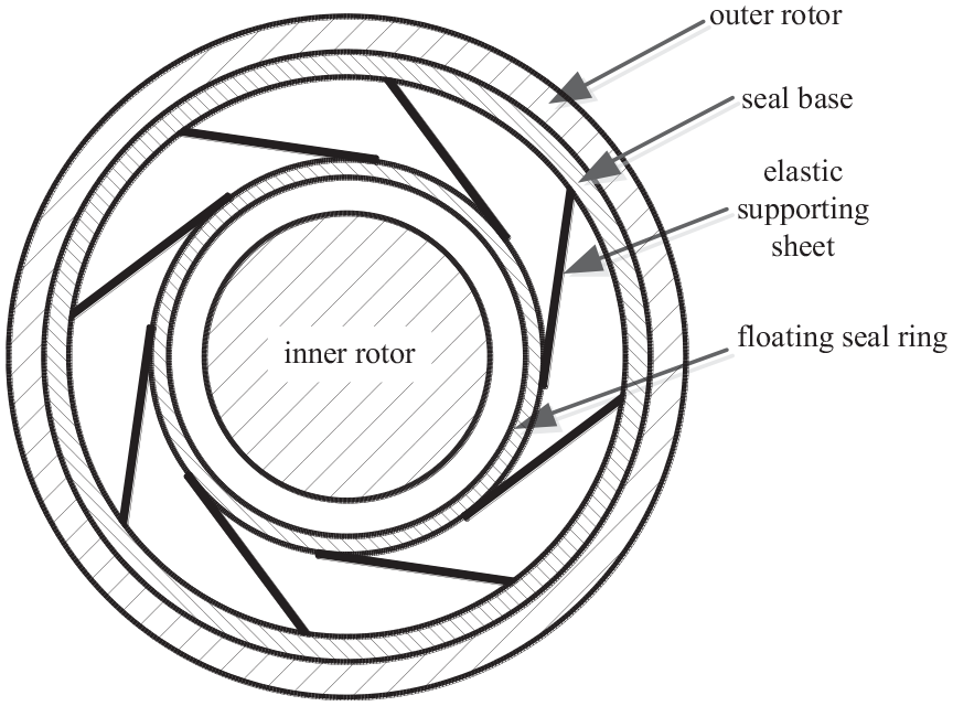
Schematic of compliant cylindrical intershaft seal.

Explosive schematic of compliant cylindrical intershaft seal.
The two rotors are misaligned when the aero-engine is running. Whether one or both of the rotors is in precession or eccentricity run out, the center of the floating seal ring and the center of the inner rotor will have an eccentricity, and a circumferentially convergent clearance is formed between the floating seal ring and the inner rotor surface. Because the two rotating walls drive the gas to produce aerodynamic lubrication in the circumferential clearance, the non-contact friction between the floating seal ring and the inner rotor is created.
Theory
Geometrical relation and force condition of floating seal ring
The state of compliant cylinder intershaft seal under the condition of rotor circular precession is shown in Figure 3. The solid line indicates the state of the elastic supporting sheets and the floating seal ring under the circular precession of the rotor. The center

Seal structure state and geometric relationship of rotor in circular precession.
Taking the floating seal ring as the object, the force and displacement of floating seal ring can be analyzed. Due to the small eccentricity of the rotor, the radial force exerted by the seal membrane on the floating seal ring under the gas pressure is approximately uniformly distributed along the circumference direction. Therefore, the resultant force of the seal membrane acting on the floating seal ring is negligibly small. If the inner rotor is in circular precession, the eccentricity of the circular precession is the centerline
The geometric relationship among the circular precession eccentricity

In addition to the hydrodynamic gas film force, due to the eccentricity
Force calculation of floating seal ring
Calculation of gas film force
When the inner rotor is in circular precession, the floating seal ring and inner rotor produce aerodynamic film force due to eccentricity. According to the assumptions of the gas bearing theory,18,19 Reynolds equation in isothermal state is used to solve the hydrodynamic gas film force. When the floating seal ring and the inner rotor are in synchronous precession, there is no relative precession between them, and only the inner rotor rotates relative to the floating seal ring. At this time, the established aerodynamic pressure field rotates in space with their precession.16,17 The differential equation of steady-state gas film pressure field in rotating coordinate system is as follows

Because of

In the ideal state, the relationship among gas density

where
The equation of gas lubrication 20 in isothermal process is obtained by substituting equation (3) into equation (2)

The dimensionless parameters can be selected as follows

Then, the dimensionless gas lubrication equation 21 is deduced as

where
The dimensionless gas film thickness equation is defined as

The periodic boundary condition for numerical solution is given as follows 22

The inlet and outlet pressure boundary conditions are, respectively, given as 23


where
Newton–Raphson method is adopted to discretely solve the nonlinear Reynolds equation,24–26 and the pressure distribution is obtained. Then the gas film force is obtained by Simpson integration of pressure distribution. If the resultant force in the eccentric direction of the rotor center and the floating seal ring center is

The resultant force of the dimensionless gas film can be derived as

The deviation angle satisfies the relation below

The dimensionalized gas film force is as follows

Calculation of centrifugal force
It is assumed that the center of mass of the floating seal ring is at its centroid. When there is an eccentricity

where
Calculation of restoring force of elastic supporting sheets
Because the circular precession amplitude of the rotor and the clearance between the floating seal ring and the inner rotor are very small, the radial displacement of the floating seal ring is also slight, which can be regarded as linear elastic support, and the restoring force of elastic support can be treated as an equivalent spring. Due to the complexity of the structure, it is necessary to calculate the equivalent stiffness of the elastic support by finite element method. Thus, the restoring force of elastic support sheets in the direction

where
Force–balance relationship
Under the steady-state condition, the floating seal ring bears the gas film force

The eccentricity
Calculation of axial leakage rate
The gas leakage characteristic is a valuable index to evaluate gas film seal performance. The mass flow rate through any axial section per unit of time is as follows27,28
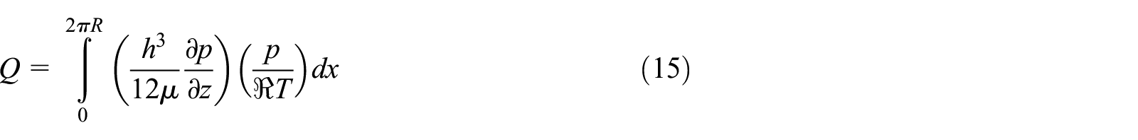
where
Calculation domain and grid
To calculate the gas film force, it is necessary to simplify the fluid domain. The leakage passage of fluid domain is the clearance between floating seal ring and inner rotor (Figure 1), which is the same as the domain of gas-lubricated journal bearings. As assumed in section “Calculation of gas film force,” the gas pressure is constant along the direction of film thickness. For the convenient of numerical calculation, the annular fluid domain can be cut open along the maximum film thickness. Thus the calculation domain becomes a rectangular region. Naturally, the circumferential direction and axial direction can be defined according to this rectangular region. Hereby, the density of grids can be controlled by the number of the division along the two directions, and the rectangular region (the fluid domain) can be meshed with rectangular grids. In this article, the circumferential direction is divided into 180 and axial direction is divided into 80.
Calculation process
The geometric relationship among eccentricity

Coupling calculation process.
Calculation of model parameters and verification
Calculation data
The seal structure parameters and operating condition data are listed in Table 1.
Seal structure parameters and operating condition data.

Grids and pressure profiles
In section “Calculation of gas film force”, we assumed that the fluid pressure is independent of the gas film thickness. As described in section “Calculation domain and grid”, the annular fluid domain can be cut open along the maximum film thickness. Therefore, the fluid domain can be simplified to a planar two-dimensional area. The detail of grids can be seen in Figure 5. The density of grids can be controlled by

Detail of grids.
Gas pressure distribution with sparse grids.
Gas pressure distribution with medium grids.

Gas pressure distribution with fine grids.
Verification of program accuracy
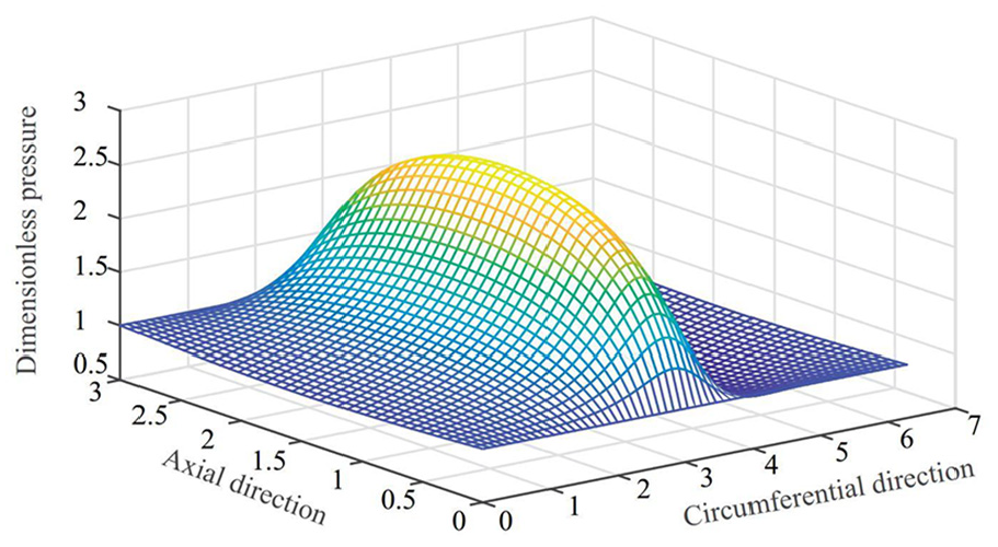
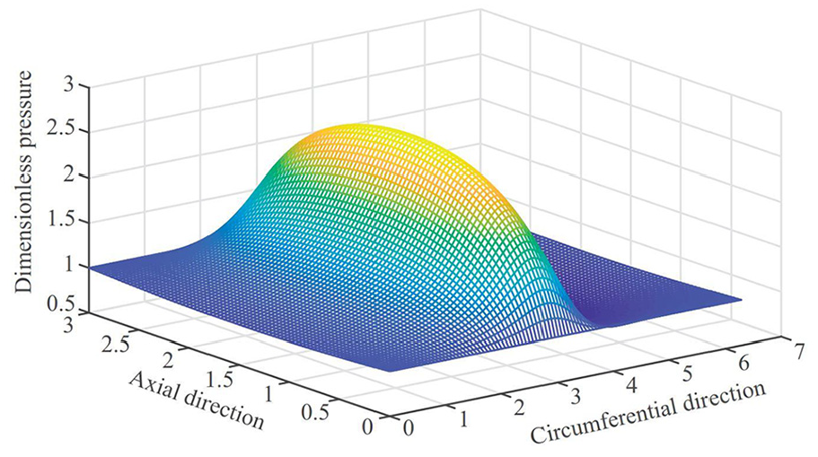
For the core calculation program, the dimensionless pressure distribution on the axial middle section of the seal, shown in Figure 9, is calculated at the width to diameter ratio

Dimensionless gas film pressure distribution in the middle section calculated by self-programming.

Results and discussion
Pressure distribution characteristic
Figure 11 shows the pressure distribution in the middle section of the seal with different seal width at an inlet pressure of 0.2 MPa and an outlet pressure of 0.1 MPa. It can be seen that the maximum pressure increases with the increase in the seal width; because the axial width of the seal is broadened, the axial leakage passage lengthens, the leakage obstruction becomes larger, and the hydrodynamic effect at the same rotor speed is enhanced.

Pressure distribution in the middle section with different axial width of seal.
The comparisons of pressure on the axial middle section under homodromy/counter-rotating at different rotational speed conditions are shown in Figure 12. It is clear that when the rotational speed values under the two conditions are the same, the maximum gas film pressure under homodromy condition is prominently greater than that under the counter-rotating condition. It can be concluded that the hydrodynamic effect under homodromy condition is enhanced, and the generated gas film force is large while the hydrodynamic effect under counter-rotating condition is weakened, and the generated gas film force is small. Because the hydrodynamic effect is produced by the physical mechanism, the solid surfaces use the viscosity of the fluid to drag the fluid into a narrow convergent gap. If one surface drags the fluid inward and the other one drags the fluid outward (counter-rotating), then there will be less fluid entering into the gap. Thus, the pressurization effect is reduced naturally.

Comparisons of pressure on the axial middle section under homodromy/counter-rotating condition.
Influence of seal width
Figure 13 plots the relationship between the floating seal ring eccentricity and the seal width at a floating seal ring speed of 13,000 r/min, a rotor speed of 16,000 r/min, an inlet pressure of 0.3 MPa, and a circular precession eccentricity of 0.1 mm. Regardless of the rotation direction of the two rotors, the seal width is larger, and the eccentricity of the floating seal ring grows larger as well. The reason is that as the width of the floating seal ring increases, the centrifugal force generated by the floating seal ring is greater than the increase in the gas film force. With equal seal width, the eccentricity of the floating seal ring under homodromy condition is greater than that under counter-rotating condition. The reason behind this is that the hydrodynamic effect under homodromy condition is strong and the gas film force is large, while the hydrodynamic effect under counter-rotating condition is weak and the gas film force is small. The larger gas film force causes the larger eccentricity of the floating seal ring, as well as the larger centrifugal force. Therefore, the resultant force of gas film force and centrifugal force leads to the notion that eccentricity of the floating seal ring under homodromy condition is significantly greater than that under counter-rotating condition.

Influence of seal width on eccentricity of floating seal ring.
Figure 14 shows the influence of different seal width on leakage rate under two types of rotation when the floating seal ring rotates at 13,000 r/min, the rotor rotates at 16,000 r/min, the inlet pressure is 0.3 MPa, and the rotor eccentricity of circular precession is 0.1 mm. Regardless of the rotation direction of the two rotors, with the increase in the seal width, the leakage rate decreases. When the seal width increases from 20 to 40 mm, the leakage rate under homodromy condition reduces about 73.9%, and the leakage rate under counter-rotating condition reduces about 71.4%. The reason is that the width of the seal directly influences the length of the leakage passage. The short leakage passage means small leakage hindrance and easily to leak. The longer the axial leakage passage is, the more it helps to prevent the leakage. Under equal seal width, the leakage rate under homodromy condition is smaller than that under counter-rotating condition, the reason being that the hydrodynamic effect under homodromy condition is stronger than the hydrodynamic effect under counter-rotating condition. The pressure changes along the axial direction more slowly when the hydrodynamic effect is strong, and the slower axial pressure change results in a lower leakage rate.

Influence of seal ring width on leakage rate.
Influence of rotor circular precession eccentricity
Figure 15 depicts the effect of the rotor circular precession eccentricity on the eccentricity of the floating seal ring under two types of rotation at floating seal ring speed of 13,000 r/min, rotor speed of 16,000 r/min, inlet pressure of 0.3 MPa and seal width of 20 mm. As the eccentricity of the rotor circular precession increases, the eccentricities of the floating seal ring under the two types of rotation show a rise trend, because the increase in the eccentricity of the rotor circular precession leads to a large eccentricity of the floating seal ring, which is driven by the gas film force along the radial direction. Since the hydrodynamic effect is stronger under homodromy condition than that under counter-rotating condition, the gas film force under homodromy condition is larger than that under counter-rotating condition; with equal rotor circular precession, the floating seal ring eccentricity under homodromy condition is greater than that under counter-rotating condition. As the rotor circular precession increases, the difference in floating seal ring eccentricity under the two types of rotation also augments. The reason is that the resultant force under the combined action of gas film force and centrifugal force is greater than that under counter-rotating condition, and the resultant force under homodromy condition increases larger than that under counter-rotating condition with the rise in the rotor circular precession.
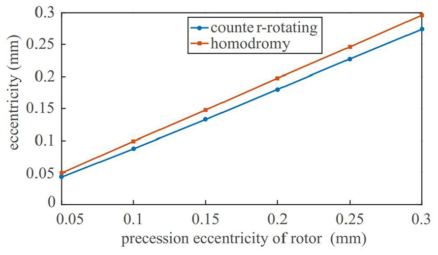
Influence of rotor circular precession eccentricity on floating seal ring eccentricity.
The influence of eccentricity of rotor circular precession on seal leakage rate at floating seal ring speed of 13,000 r/min, rotor speed of 16,000 r/min, inlet pressure of 0.3 MPa, and seal width of 20 mm is presented in Figure 16. It is obvious that the rotor circular precession eccentricity has a larger influence on leakage rate under counter-rotating condition than that under homodromy condition. But there is little difference in numerical value under the two types of rotation. According to the analysis of Figure 15, when the rotor circular precession eccentricity increases, the eccentricity of the floating seal ring rises, resulting in an increase in the elastic restoring force of the floating seal ring, and the centrifugal force of the floating seal ring also increases. Owing to the force–balance relationship, the gas film force is changed by the increase in the other two forces. Under homodromy condition, the hydrodynamic effect is strong, and the leakage clearance changes slightly, which results in a significant change in the gas film force. Under homodromy condition, the restoring force and centrifugal force increase in the same magnitude. The force–balance relationship causes the seal clearance between the floating seal ring and the rotor to change slightly, and the leakage rate also changes slightly. This may be due to the fact that the hydrodynamic effect under counter-rotating condition is weakened, while the hydrodynamic effect under homodromy condition is enhanced. Under the same inlet/outlet pressure, the stronger the hydrodynamic effect is, the more significant the hindrance to axial leakage will be. Under counter-rotating condition, it needs significant changes of gas lubrication eccentricity (the eccentricity between the floating seal ring and the rotor) to balance the centrifugal force and the elastic restoring force. At the same rotational speed value, the larger the gas lubrication eccentricity is, the higher the leakage rate will be; therefore, the leakage rate under counter-rotating condition is higher than that under homodromy condition.

Influence of rotor circular precession eccentricity on leakage rate.
Influence of rotational speed
Figure 17 shows the influence of the floating seal ring rotational speed on the seal leakage rate under the condition that the rotor is 16,000 r/min, the inlet pressure is 0.3 MPa, and the eccentricity of the rotor is 0.1 mm. It can be seen that the gas leakage rate decreases with the increase in the floating seal ring rotational speed regardless of the rotation direction of the two rotors. When the floating seal ring speed increases from 11,000 r/min to 15,000 r/min, the leakage rate under homodromy condition decreases by 35.9% and the leakage rate under counter-rotating condition decreases by 26.1%. The reason is that the growth of rotational speed of the floating seal ring leads to an increase in the centrifugal force. Owing to the force–balance relationship, the gas lubrication eccentricity decreases. Thus the axial leakage rate reduces as well. The gas lubrication eccentricity under homodromy condition is smaller than that under counter-rotating condition, and the leakage rate under homodromy condition is naturally smaller than that under counter-rotating condition when the other factors are the same.

Influence of rotational speed of floating seal ring on leakage rate.
Figure 18 describes the relationship between rotor speed and axial leakage rate at the floating seal ring speed of 13,000 r/min, inlet pressure of 0.3 MPa, and rotor precession of 0.1 mm. It is clear that with the increase in rotor speed, the leakage rate decreases and the leakage rate under counter-rotating condition is higher than that under homodromy condition. When the rotor speed increases from 14,000 to 18,000 r/min, the leakage rate under homodromy condition decreases by 15.8%, and the leakage rate under counter-rotating condition reduces by 14.4%. The reason is that the rotational speed of the rotor affects the gas film force, and the hydrodynamic effect under homodromy condition is strengthened while the hydrodynamic effect under counter-rotating condition is weakened. For the same value of gas film force, the corresponding gas lubrication eccentricity under homodromy condition is smaller than that under counter-rotating condition. Therefore, the leakage rate under counter-rotating condition is higher than that under homodromy condition.
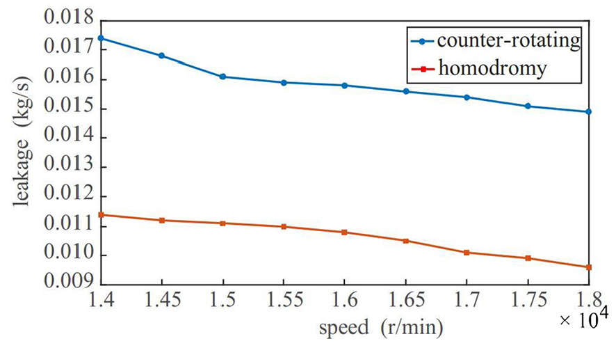
Influence of rotor rotational speed on leakage rate.
Influence of seal radius
Figure 19 delineates the influence of the rotor radius on the leakage rate when the nominal radial clearance between the floating seal ring and the rotor is 0.05 mm, the floating seal ring speed is 13,000 r/min, and the rotor speed is 16,000 r/min. Clearly, if the nominal radius clearance is constant, with the increase of the rotor radius, the axial leakage rate increases, for example, when the radius of the rotor increased from 62 to 82 mm, the leakage rate increased by 1.28 times under homodromy condition and by 1.33 times under counter-rotating condition. The reason is that the increase in the rotor radius is equivalent to the rise in the cross-sectional area of the leakage passage along the axial direction. In other words, the cross-sectional area of the annular leakage clearance increases with the increase in the rotor radius. Therefore, under the same conditions, the leakage through the large cross-sectional area is naturally high.

Influence of rotor radius on leakage rate.
Conclusion
In this article, a novel type of compliant cylindrical intershaft seal structure is designed, and a steady-state aeroelastic coupling solution method is proposed for this type of seal. This structure includes two special cases: if the rotational speed of floating seal ring is 0, it degenerates into the conventional dynamic seal; if the rotational speed of floating seal ring is 0 and the elastic support stiffness is infinite, it becomes a 360° rigid circular gas bearing. The following conclusions are drawn from the compliant cylindrical intershaft seal.
The leakage rate of the compliant cylindrical intershaft seal decreases with the increase in the seal width regardless of the rotation direction of the two rotors. Under the structural conditions studied in this article, as the seal width doubles, the leakage rate under homodromy and counter-rotating conditions, respectively, decreases by 73.9% and 71.4%.
The leakage rate of compliant cylindrical intershaft seal rises with the growth of the eccentricity of the rotor circular precession under counter-rotating condition, and hardly changes with the eccentricity of rotor circular precession under homodromy condition.
With the rise in the rotor radius, the leakage rate increases under the two types of rotation. At the same operating condition and rotating speed value, the leakage rate under homodromy condition is smaller than that under counter-rotating condition.
For the dual-rotor cylindrical seal, the hydrodynamic effect is enhanced under homodromy condition, while the hydrodynamic effect is weakened under counter-rotating condition. And the maximum gas film pressure under homodromy condition increases significantly compared with that under counter-rotating condition. If the hydrodynamic cylinder seal is applied in intershaft seal, the seal performance under homodromy condition is better than that under counter-rotating condition.
Footnotes
Appendix 1
Declaration of conflicting interests
The author(s) declared no potential conflicts of interest with respect to the research, authorship, and/or publication of this article.
Funding
The author(s) disclosed receipt of the following financial support for the research, authorship, and/or publication of this article: This study was supported by the National Natural Science Foundation of China (Grant No. 51575445).