
Abstract
The looseness of tires or even falling off from cars will lead to serious traffic accidents. Once it occurs, it will bring casualties and huge economic losses to society, seriously affecting the traffic safety. To mitigate such possible safety concerns, an early loosening warning system is developed in this article. The system consists of the tire monitoring module and the working control module. The tire monitoring module is installed on the tire and is designed with no power supply. The control module is installed in the vehicle body. Signal transmission between the two modules is achieved through wireless radio frequency. In the driving, once the tire is loosened, the monitoring device will send out the alarm signal automatically and wirelessly. After the driver gets the alarm signal, he can immediately perform the emergency processing, parking, and inspection, which can avoid traffic accidents caused by it. This article introduces the detailed structure, working principle, and operation process of the system. This early warning system has simple structure, high reliability, and is easy to use. It can be used in the common working environment of automobiles. Meanwhile, it is also the foundation of intelligent connected vehicle.
Introduction
On 2 January 2015, there was a severe traffic accident due to the tire falling off while driving near the Western Station of Yangzhou. Three accidents like this had been occurring in Yangzhou for 2 days. 1 Another accident occurred on 15 December 2013, while a sanitation worker was cleaning the road in Zhengzhou. At the same time, the left rear wheel of a running cement tanker suddenly fell off. The flying wheel hit her on the ground while she was working, and she died on impact. 2 There are many traffic accidents caused by the looseness of automobile tires. Although the probability of this failure occurring is not very large, once it occurs, it might cause the overturn of vehicles, which could lead to severe accident.
With the development of science and technology, the smart technology of automotive tire is increasingly being studied and applied. Kim et al. 3 proposed a tire model and an intelligent tire simulation to reduce the cost of developing an intelligent tire system, getting tire-related variables directly from tire strain. At the same time, there have been growing demands of people for the safety in driving. It is necessary to develop the early warning system for the loose auto tire. Technically, it can also be supported. In the relevant literature, no research is precisely the same as this early warning system. From the point of application, the research similar to this is the tire pressure monitoring system. There are many types of research on tire pressure. The monitoring and managing of tire pressure, using the micro-controller with a wireless transmitter and tire pressure monitoring device, were described in the paper by Kowalewski. 4
In the study of Liang et al., 5 in order to feed back and control the air pressure within the tire, the design of a closed-loop tire pressure monitoring and control system was described. At present, almost all products in the tire pressure monitoring system have the power mode, which means that there is a power supply device at the tire monitoring module. In connection with this, some scientists are studying how to convert the strain energy caused by deformation of the tire while driving into useful electrical energy. Radio frequency identification (RFID) systems are relatively safe and standardized, and their related technology applications are being widely used, such as identity management, near-field communication, and electronic article surveillance. 6 Other researches focus on the auxiliary driving system. For example, Wu et al. 7 developed a reasoning-based framework for the monitoring of driving safety. In this study, this information, lane bias, the distance to the front car, longitudinal and lateral accelerations, and speed data from sensors installed in a real vehicle were collected.
In the research of Hu et al., 8 a quantitative evaluation method of driver’s driving behavior is proposed, which is applied to detect abnormal driving behavior. In the research of Iranmanesh et al., 9 the neural network method is used to detect driver’s distraction.
Based on these research results, a set of loose tire early warning system (LTEWS), in which there is no power at the tire monitoring module, was developed in this article. This system has the characteristics of energy-saving, simple structure, reliable performance and convenient operation. The composition and working principle of the alarm system are described in the second part. Its use process and description are given in the third part. The performance characteristics and innovation of the alarm system are introduced in the final part of the article.
The constitution and principle of loose tire early warning system
The structure and principle of hardware system
Figure 1 is the electrical schematic of the LTEWS. The system consists of two modules: the monitoring device 1 assembled on the tire and the control device 2 assembled on the vehicle body. In Figure 1, the solid arrow indicates the transmission of the wire signal, and the dashed arrow indicates the transmission of the wireless signal. The heavy continuous line indicates the transmission of the system to the external signals.
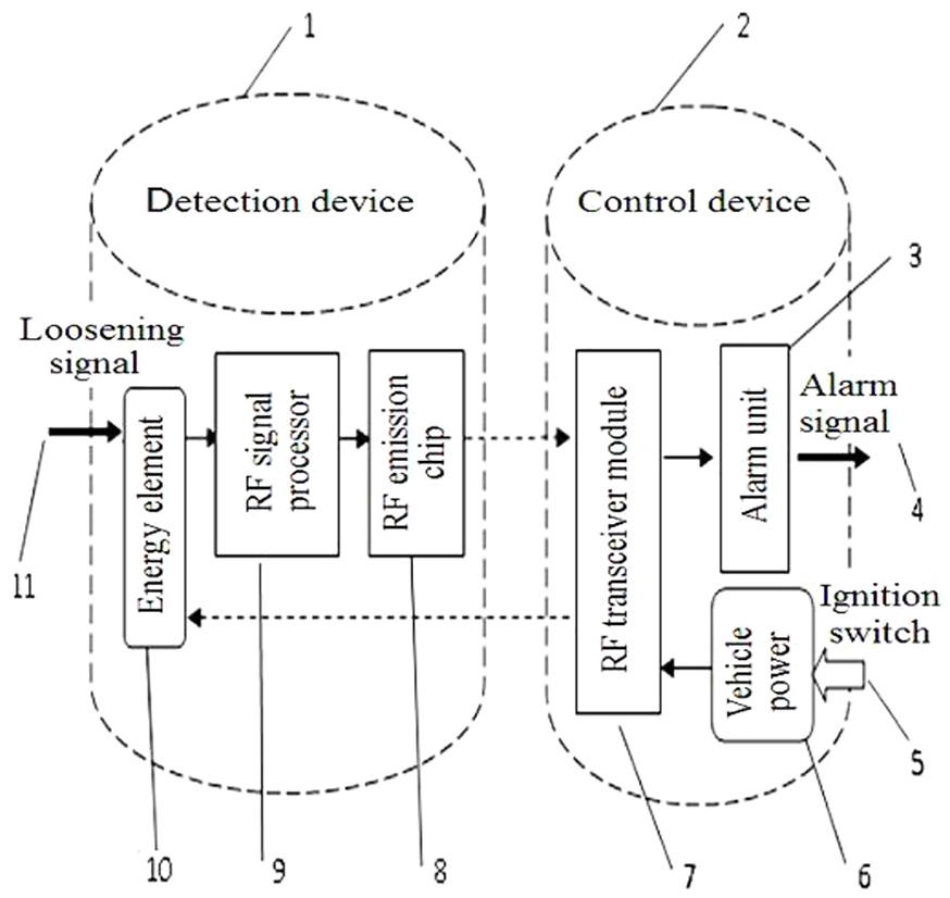
The electrical schematic of LTEWS.
The tire loosening monitoring device 1 comprises the radio frequency emission chip 8, the radio frequency signal processor 9, the energy storage element 10, and the input of tire loosening signal 11. The control device 2 of the LTEWS includes the loosening alarm unit 3, the output of alarm signal 4, the input signal of ignition switch 5, the vehicle power 6, and the RF transceiver module 7. The monitoring device 1 is connected with the control device 2 through the radio frequency signal. This connection enables the communication between the control device fixed on the vehicle body and the monitoring device following the tire rotation.
The control device 2 is located in an easy-to-hold position in the middle of the vehicle body, which is about the same distance from each tire. Its functions include sending the car key trigger signal to wake up monitoring device, receiving the tire loosening information sent out by the monitoring device, analyzing the signal, and generating an alert if the tire comes loose. When the car key is inserted, the ignition switch signal 5 will be triggered, and the vehicle power 6 provides power supply and work for the control device 2 of the LTEWS. The radio frequency transceiver module 7 sends out the radio frequency signal, which causes the coil 10 in the energy storage element to generate and store the electric energy. This energy will wake up the monitoring device 1 and supply the power for it. When the tire is fastened and firm, the radio frequency transceiver module 7 receives the normal response signal, and the loosening alarm unit 3 does not output the alarm signal. Once the tire is loose, the monitoring device 1 is out of power and can’t send out the normal response signal. The radio frequency transceiver module 7 will make loose alarm unit 3 to send an alarm signal.
Figure 2 is the axonometric drawing of the assembly structure of the tire loosening monitoring device. In the figure, 1 is the elastic gasket, 2 monitoring module, 3 energy storage coils, and 4 and 5 storage coil two terminals.

The axonometric drawing of the assembly structure of the monitoring device.
Each tire must have at least one monitoring device. It is also possible to install a monitoring device on each fastening bolt. The structure of the monitoring device is shown in Figure 2. The monitoring module 2 and the energy storage coil 3 are embedded in the spring washer. The monitoring module is mounted on the fracture of the spring washer. The energy storage coil is embedded in the groove of the end face of the spring washer. When installing, put it on the fastening bolt, and then tighten the fastening nut to fix the tire. The monitoring device rotates with the tire and can be used for detecting, changing, and sending the signals when the tire fastening bolt loosens. The energy storage coil 3 serves as a power source of the monitoring module 2. When the bolts are fastened firmly, the terminals 4 and 5 at both ends of the bolts are closely fitted with the power input terminals of the monitoring module to provide power for the monitoring module 2. And the RF signal processor of the monitoring module will control the RF transmitter chip to send a signal which means that there is not any problem with the tire. When the tire fastening bolts loosen or break, the opening of the elastic gasket 1 tilts up and the terminal 5 will be disconnected from the monitoring module 2. And the energy storage coil 3 cannot supply power to the monitoring module. The monitoring module without power can’t send the tire fastening signal.
The assembly location of monitoring device
In Figure 3, 1 is the rim, 2 is the hub, 3 is the fastening bolt, and 4 is the monitoring device. The monitoring device is installed on the outer side of the rim and fitted on the fastening bolt, which can detect the rim loosening caused by bolt breakage or nut loosening at the fastest speed.

The assembly position diagram of the monitoring device.
The detection device, as a part of the system, is exposed outside the body, so the design of moisture-proof and water-proof is necessary. As shown in Figure 2, excluding the two terminal contact conduction positions of 4 and 5, in other parts of electrical equipment, that is, energy storage coil and detection module, the protection grade of IP56 in IEC/EN60529 can be achieved by bonding and sealing with silica gel, which fully meets the use requirements of this product.
The control process of software system
The software control of the system is located in the control device of LTEWS, installed in the car body. When the car is in the “on” position, the control device is powered. The control device initializes the system parameters. After initialization, it transmits a handshake signal to the monitoring module in the hub. If the tire is properly tightened, the monitoring module generates a response signal. At this time, the control module displays the normal status indicator. If the tire is loose, the monitoring module cannot send a response signal within the specified time. Then, the counter is incremented by 1. If the accumulated time exceeds 10 s, an early warning signal is output. Figure 4 presents the control process chart of software system.

The flowchart of software control.
The application of this alarm system
The steps and methods of using the above system
The procedure for using LTEWS is as follows:
Step 1: install. Assemble the monitoring module, energy storage coil, and elastomeric gasket together. Put the entire assembled monitoring device on the rim fastening bolts of the car, tighten the nuts, and install the rims and tires. The control device is fixed on the body, and the power lead of the control device is connected with the on-vehicle battery through the ignition switch, so that the battery controlled by the ignition switch could provide power for the control device.
Step 2: the using of system. It will be divided into the following three situations: (1) The car tire is normal and is in the drive. At this point, the ignition switch is energized and the control device receives power. The RF transceiver module operates and emits the radio frequency signal. The coils of the energy storage element in the monitoring device receive signals, generate electrical energy, and store energy. The radio frequency signal processor works and controls the radio frequency transmitting chip to send the radio frequency response signal, and the radio frequency transceiver module accepts the response signal which means that it isn’t failing and does not alarm. (2) Tire is loose and the car is in the driving state. At this time, the RF transceiver module is powered and works. The RF transceiver module emits the radio frequency signal as usual, so that the energy storage element can also generate electrical energy. But the opening of elastic gasket is tilted under the elastic restoring force because the bolts of the fastening wheel rim are loose. The terminal is separated from the monitoring module. And then the monitoring module cannot be powered. Therefore, the monitoring device can’t send the response signal. If the RF transceiver module does not receive the response signal, it will control the alarm unit to send an alarm signal. (3) Parking status. At this moment, the ignition switch is in the off state. The control device is not allowed to be powered. It does not work, and no alarm signal is generated.
Step 3: handling alarms. Once the tire loosens alarm signal, the driver immediately stops for maintenance.
In addition, the alarm system can also be used in conjunction with other vehicle driving systems. For example, in the research of Yin et al., 10 a danger-level framework and its feature extraction method are proposed to analyze driving data. The tire loosening warning signal in this article can be used as one of the high-level hazard features.
The power efficiency of this system
The maximum distance for the RF transmission is approximately the length of the car’s body in this alarm system; the required power is expressed as

Ploss is power loss on the transmission path and the unit is denoted by dB, d is the transmission distance (km), and f is the system frequency (MHz).
In the above formula (1), the transmission distance of the system takes 0.01, and the frequency takes 1.
The results are calculated as follows

Next, according to the formula

We can get Ploss(W) = 0.18 from formula (2).
The power of the common RF module is about 2(W), and it is sufficient to meet the power requirement of the system.
The features and innovations of this system
In addition to its simple structure, ease of use, and high reliability, this system is also applicable to the common working environment of automobiles.
1. Working temperature. The monitoring module of the alarm system is installed on the bolts of the hub. Its ambient temperature ranges from −40 to 120 degrees Fahrenheit. The control module of the alarm system is mounted on the vehicle body, and its ambient temperature range is −40–80 degrees Fahrenheit.
2. Receiver sensitivity, which is greater than −80 dBm.
The system uses the common chips, coils, circuits, and other components to meet the requirements of the use of the environment.
3. The reaction speed of this device. The sampling frequency of the system is 2 Hz. The loosening of bolts leads to the loosening of tires, and there must be a certain time delay from the loosening of bolts to the loosening of tires. Because the system responds to the bolt loosening signal, the system that transmits the tire loosening signal to the driver through the working frequency of 2 Hz can meet the safety requirements.
There are two innovations in this system:
The research of the loosening alarm system for automobile tires developed in this article has achieved the alarm purpose for the loose tires. There is not any relevant report on such research.
The system realizes the power-free design of the monitoring module, which has a simple structure and high reliability. And it has not been adopted in similar products (such as a tire pressure monitoring system).
Conclusion
In order to solve the problem of severe vehicle accidents caused by loose tires and even the falling of tires, the LTEWS for car was developed in this article. In the driving, once the tire is loosened, the monitoring device will send out the alarm signal automatically and wirelessly. After the driver gets the alarm signal, he can immediately perform the emergency processing, parking, and inspection, which can avoid traffic accidents caused by it. The alarm system is low in cost and easy to use, improving the intelligence level and safety performance of the vehicle, and has broad application prospects. This alarm system can be used for various vehicles such as trucks, cars, and buses. The results of this research can recognize the automatic control of automobile driving safety in the tire and promote the development of the intelligent connected vehicle.
Footnotes
Declaration of conflicting interests
The author(s) declared no potential conflicts of interest with respect to the research, authorship, and/or publication of this article.
Funding
The author(s) disclosed receipt of the following financial support for the research, authorship, and/or publication of this article: This study was supported by the innovation fund of Nanjing College of Information Technology (grant number: KJ17006).