
Abstract
The stagnant region often appears in front of the tool cutting edge, which is caused by mechanical inlay and excessive pressing in plastic metal cutting with large negative rake angle tools at a low speed. It results in the change of the effective negative rake angle which can affect the flow characteristics of material, the quality of machined surface and the abrasion loss of cutting tools. However, the critical negative rake angle model based on the existence of the stagnant region has not been reported yet. Therefore, in order to investigate the critical negative rake angle value considering the stagnant region, a critical negative rake angle model based on the principle of minimum required energy is established, and the correctness of the theoretical model is verified by orthogonal cutting experiments. At the same time, the influence of the critical value of the large negative rake angle tool on the machined surface quality is studied through different cutting experiments. These experimental results show that the deviations of both experimental and theoretical critical negative rake angle are less than 5% during the orthogonally cutting of the aluminium (AL1060) and copper (T2) materials by the negative rake angle tool. Meanwhile, the critical negative rake angle is related to the adhesive friction coefficient of tool–workpiece contact surface. The analysis of friction characteristics shows that the deviation values of both theoretical and experimental critical negative rake angle are proportional to the coefficient of adhesive friction and the thickness of the stagnant region. Critical negative rake angle has a significant effect on roughness and residual stress of the machined surface.
Introduction
The study of critical negative rake angle (CNRA) with a large RNA tool, as well as that of the minimum uncut chip thickness (MUCT) with the rounded-edge cutting tool in micro-cutting, is aiming for establishing the relationship between the effective negative rake angle (ENRA) of the tool and cutting process parameters in cutting and ploughing critical state. Therefore, the CNRA of large negative rake angle (NRA) tools might be investigated by using the MUCT methods of rounded-edge tool in micro-cutting. Because the radius value is approximately equal to the cutting thickness in micro-cutting with rounded-edge tools and single-particle grinding, the variation of the cutting thickness will cause the changes of ENRA. As a result, the MUCT value becomes the critical criterion for the action of cutting and ploughing. And it determines the flow characteristics of the processed material, the quality of the machined surface, 1 the wear amount of the tool 2 and so on. For most special processing methods, such as mechanical scratch 3 and ruling, 4 the cutting thickness value is greater than the rounded-edge tool radius value in the micro-cutting with the large NRA tool. In order to achieve high surface quality, it is necessary to consider the cutting and ploughing effect of the large negative rake face and the material pressing effect of tool rounded-edge on shaping action. Meanwhile, the work NRA of the tool is a constant that does not vary with the cutting thickness. Thus, the CNRA is the critical criterion for the action of cutting and ploughing when the NRA tools scratch or rule the metal material.
The research method of MUCT is diversified, including the theoretical method of the minimum cutting thickness established by the mechanics of cutting, the cutting test method, the finite element cutting simulation method and so on. For example, Son et al. 5 pointed out that the MUCT was related to the blunt radius of the rounded-edge tools and the friction coefficient, and the MUCT analysis model was established based on the assumption that the shear angle was equal to the shunt angle; it was found that the friction coefficient increased with the rounded-edge tool radius value reducing, and the MUCT value could be reduced through the cutting test. Ikawa et al. 6 drawn a conclusion that the actual geometric angle of the tool involved in cutting had a great influence on the MUCT during the cutting process. Malekian et al. 7 obtained a new analytical method of finding the MUCT for rounded-edge tools based on the principle of minimum required energy and the infinite shear strain method and found that the stagnant angle was equal to the friction angle between the material and the tool rake face. Basuray et al. 8 conducted the cutting experiment on carbon steel and aluminium, they indicated the MUCT at the separation angle of 37.6° by using the principle of conservation of energy and the ratio of the MUCT to the tool radius is 0.21. In addition, the sharpness of the cutting tool was found to affect the separation point thickness. Wu and Shi 9 found that the ratio of the MUCT to the cutting edge radius was about 10% by using plastic strain gradient theory. In order to reflect the effect of MUCT on the mechanical properties of materials in the micro-cutting intuitively, some scholars have carried out the research by the finite element simulation method. For example, Liu et al. 10 analysed the effect of cutting speed on MUCT and cutting edge radius by using molecular dynamics theory, and it was proved that the MUCT could be affected by cutting speed, strain and strain rate. Pang et al. 11 pointed out that the change of cutting thickness did not influence the position of the separation point and the size of the stagnant region, and the cutting edge radius was inversely proportional to the cutting speed, while the ploughing effect was proportional to the stagnant region. Lai et al. 12 suggested that the chip could not be observed when the ratio of cutting thickness to the cutting edge radius is between 0.1 and 0.2; however, the chip was generated when the ratio was greater than 0.3.
Due to the geometric characteristics of the NRA or rounded-edge tools, it often produces a stagnant region in front of the cutting edge when micro-cutting is conducted. Since Abebe 13 first proposed the dead metal zone in metal cutting with NRA tools, many scholars have carried out related investigations. Kita et al. 14 found that the top of the stagnant region became deeper as the tool cutting speed increased, and the material in front of the tool flowed upwards along the tool surface when the cutting speed was too high. Makino and Usui 15 proposed that the relationship between the growth time of the stagnant region and the performance of the cutting material was not clear, and a large plastic deformation region could be observed when the metal was cut at a low speed or with a large NRA tool. Weule et al. 16 also pointed out that lower cutting speed was an important factor in the formation of stagnant region, which was accompanied by poor surface roughness. Kountanya and Endres 17 found that a stagnant region was formed in front of the cutting edge when the brass material was orthogonally cut with a rounded-edge tool, and the stagnant region disappeared when the rounded-edge tool orthogonally cut the zinc material. The results of Ozturk 18 revealed that the area of the stagnant region in the orthogonal cutting model would grow up with the absolute value increasing of the tool NRA, and the increase of the ratio of pressure and cutting force would improve the quality of the machined surface. However, it did not explain well whether large NRA (absolute values above 70°) had any effect on the stagnant region. Based on Lee and Shaffer’s model, Fang and colleagues19,20 presented an analytical slip-line field model with a stagnant region, which investigated the NRA, and the cutting speed affected the friction characteristics of tool-chip and the quality of the machined surface.
According to previous work mentioned above, the MUCT is mainly related to the cutting tool edge radius, cutting thickness, cutting speed and friction characteristics of the tool–workpiece. However, the tool ENRA can be changed by the variation of the cutting edge radius, cutting thickness and cutting speed (which will change the tool–material contact length). Apparently, the MUCT value is mainly affected by the ENRA and the friction coefficient of tool–workpiece. At the same time, the stagnant region, which changes the ENRA and then affects the material flow characteristics, usually forms in front of the tool cutting edge when orthogonal cutting was conducted with rounded-edge or large NRA tools. Therefore, it is necessary to consider the stagnant region in front of the cutting edge during the large NRA tool cutting and ploughing action. Moreover, the CNRA model based on the existence of the stagnant region has not been reported yet. So, the CNRA value will be explored based on the stagnant region by studying the friction characteristics of tool–workpiece friction pairs and the deviation of experimental CNRA and theoretical CNR in micro-cutting in this work.
Establishment of the CNRA model
Compared with the blunt tool edge, the large negative rake face will play a dominant role in the plastic flow characteristics and mechanical properties, when the cutting thickness is greater than the cutting tool edge radius (

Mechanics model of orthogonal cutting with an NRA tool.
Ohbuchi et al. 21 conducted the S45C orthogonal cutting experiment with large NRA tools, and it revealed that the negative rake face had the effect of pressing and shaping on the material. A stagnant region which could be expressed by the ACE region was formed in front of the tool rake face. Ozturk et al. 23 found that a stagnant region expressed by BEC region was formed in the orthogonal cutting experiment with radius tools. As the cutting thickness is greater than the cutting edge radius illustrated in Figure 1, the dead metal region BEC will be enveloped in the ACE region; the ACE region is the eventually formed stagnant region, which will affect the value of effective NRA.
When the tool NRA exceeds the critical value, the friction force of the contact interface between the tool and workpiece in the cutting direction can be obtained

where l1 is the contact length of the material flowing through the stagnant point A up along the tool rake surface which equals to AD; l2 is the contact length of the material flowing through the stagnant point A down along the tool rake face and the stagnant region in front of the tool surface, it approximately equals to AC;
The friction angle is assumed to be equal to the theoretical value as

Equation (1) can be further expressed as

By the traditional shear theory model, 22 the shear force in the cutting direction obtained by the shear band deformation in the material is

where h1 is the uncut chip thickness, h3 is the height of the separation point C considering the tool edge radius effect,

The separation point height is directly related to the cutting edge radius, the uncut chip thickness and the cutting speed according to equation (5). The height of the stagnant point A is inversely proportional to the shear force known from equation (4). Energy consumption in actual cutting process is mainly composed of four parts, including the friction energy due to the contact of tool–workpiece, the shear energy of shear slip deformation occurring within the material, the surface energy of forming the new surface and the kinetic energy when the material goes through the shear plane. As the surface energy and kinetic energy account for a small proportion of the total energy, the energy consumed by the former two factors during the cutting process is investigated in this article. Therefore, the total energy of the cutting direction can be expressed as

Based on the theory of minimum required energy in the cutting direction, equation (7) can be obtained

According to the balance equation of the force, a conclusion can be drawn that the material flowing on the tool surface varies with the size of the rake angle. It can be seen from equation (7) that the cutting and ploughing action coexist when the tool rake angle is larger than the CNRA, and the material on the surface of the tool shows up-down shunting at the stagnant point A. The phenomenon will result in the friction characteristics of the higher material which is different from the lower one as the stagnant point A is the boundary. The height of the stagnant point A and the contact length of the cutter and chip are uncertain.
Therefore, the method of critical hypothesis only considering the role of simple ploughing is proposed in this article. There is no chip generation because of the tool’s pressing and shaping effect on the material. To simplify the calculation, assuming that the height of the pure plough is same as the height of the stagnant point A, equation (7) can be simplified as

where

The simplified form of equation (8) can be obtained as

The second part of equation (10) is known as a transcendental equation, and the explicit solution for ENRA does not exist. Therefore, by solving the equation for ENRA, it can be obtained

The ENRA obtained in equation (11) is the CNRA considering the existence of the stagnant region. There will be a certain difference between ENRA and ANRA, due to the uncertainty of the adhesive friction characteristics of tool–workpiece, the thickness of stagnant region and so on. On the other hand, the difference between the ENRA and ANRA will also reflect the thickness of the stagnant region during the cutting process with NRA tools. At the same time, the article deduces the CNRA value in the case of h1 > r and considering the presence of the stagnant region. The residual angle of the CNRA is equal to the stagnant angle of Malekian et al. 7 obtained using a rounded-edge tool in micro-cutting (h1 ≤ r). Based on the author’s point of view, both for large NRA (cutting thickness is greater than the cutting edge radius, and the ENRA is a fixed value) and micro-cutting (cutting thickness is less than the cutting edge radius, and ENRA is a variation), the essence is a positive correlation between the ENRA and the adhesive friction characteristic of the tool–workpiece. And the correctness of the CNRA analytical model will be verified by the orthogonal cutting experiment method in this article.
Methods and materials
The orthogonal cutting experiment method was used in the work. The experimental platform of orthogonal cutting was constructed as shown in Figure 2. The accurate precision tool setting of laser diffraction 25 could be achieved by using a He-Ne laser diffractometer and RZ-H200 area array CCD camera. A 1000× electron microscope pair was used to observe online that whether the chips were created during the cutting process (the microscope was aligned with the side of the cutting tool during the observation). The cutting force was measured and recorded online during cutting process with a high-precision NOS-C901 three-dimensional force sensor. As shown in Figure 3, the wedge-shaped natural diamond tool was used in this cutting experiment. The tool apex angle was 87.5°, edge radius was 215.6 nm and the length of the tool cutting edge was 2.65 mm. SIGMA KOKI angle fine-tuning rotary turret produced by Japan was used to clamp and rotate tools. The tool rotation angle deviation could be controlled at ±5′ to ensure the accuracy of the tool rotation angle.

Experimental platform of orthogonal cutting.
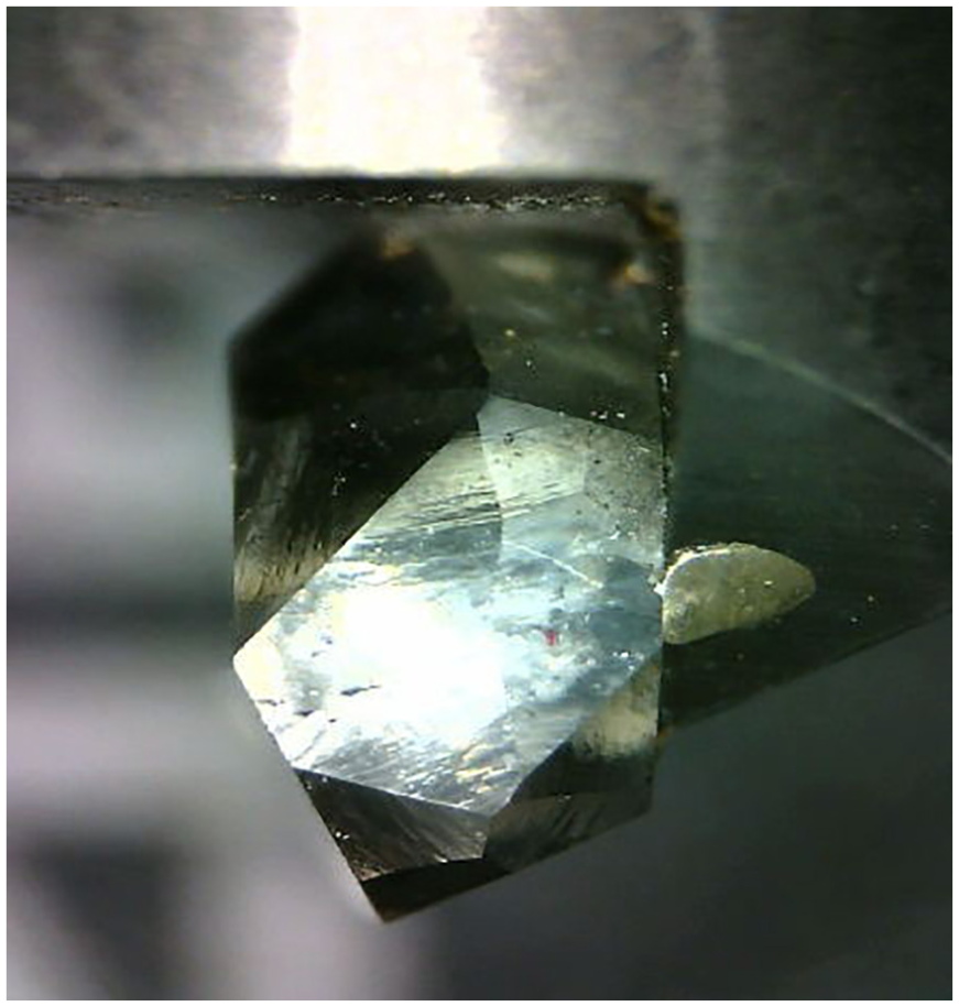
Diamond tool.
In this experiment, cutting depth of 20 μm was greater than the value of the cutting edge radius, cutting width of 2 mm was less than the width of the cutting edge and cutting speed was 1000 μm/s (low speed). The above parameters were fixed values. Two different materials of AL1060 and T2 were mainly investigated. The change rule of material flow characteristics, friction characteristics and CNRA value corresponding to different friction pairs were studied considering the variation of the NRA value from −60° to −85°.
Results and discussion
Material flow characteristics
At the same cutting conditions, the effect of the tool on the material is characterized by co-existence of cutting and ploughing when the tool NRA is between −60° and −75° (Figure 4(a)–(d)), and as the NRA becomes more negative, the material will be pushed or ploughed more strongly by the NRA tool, the shear deformation in the material is weakened and the chip morphology appearing on the rake face shows a trend of growing. When the NRA of the tool continues to change towards the negative value and then reaches the critical value of −77° (Figure 4(e)), the material is ploughed by the tool, and there is no chipping at the rake face. The experimental results also show that the CNRA of the tool is −81° (Figure 4(f)), which is obtained by orthogonal cutting of the T2 material, and the effect of the rake angle on the material flow characteristics is same as that of orthogonal cutting of the AL1060 material. The above test results indicate that the large NRA tool is similar to the rounded-edge one in micro-cutting process, and both of them have a CNRA which decides whether the chips will be deformed. At the same time, it also shows that different tool–workpiece friction pairs correspond to different CNRA values.

Side view of NRA tool cutting. (a) AL1060-NRA: −60°. (b) AL1060-NRA: −65°. (c) AL1060-NRA: −70°. (d) AL1060-NRA: −75°. (e) AL1060-NRA: −77°. (f) T2-NRA: −81°.
Apparent friction coefficient
As shown in Figure 5, the normal force FT, the tangential force FC and the force ratio FC/FT, apparent friction coefficient of the AL1060 and T2 materials, are obtained by orthogonal cutting experiments. Both the normal force and the tangential force increase, and the increasing rate of normal force is obviously greater than that of the tangential force when the NRA becomes more negative until it reaches the critical value. The normal force and the tangential force appear to be obviously smaller when the NRA approaches or reaches the CNRA; while the tool is only used to plough the material at this moment, missing of the resistant cutting force causes the resultant force to decrease rapidly. Contact pair of the tool–workpiece shows the adhesive friction characteristics. The apparent friction coefficient becomes smaller as the tool NRA becomes more negative, which indicates that the tool gradually changes the material to a low-pressure effect as the NRA becomes more negative. The apparent friction coefficient is a parameter characterizing the numerical ratio of the tangential force to the normal force. However, it does not positively reflect the friction characteristics of the tool–workpiece contact interface. The actual tool–workpiece friction pair average friction coefficient can be obtained by solving equation (12)


Time-domain graph of (a) AL1060-nomal force/N, (b) AL1060-cutting force/N, (c) AL1060-apparent friction coefficient-μapp, (d) T2-nomal force/N, (e) T2-cutting force/N and (f) T2-apparent friction coefficient-μapp.
Average friction coefficient and adhesive friction coefficient
Figure 6 shows the time-domain graph of tool–workpiece average friction coefficient of the tool–AL1060 and tool–T2 two materials friction pair at the border of cutting and ploughing effect. It can be found that the better the ductility and plasticity, the greater the average friction coefficient of the tool–workpiece at the same cutting conditions. Therefore, the CNRA of AL1060 (−77°) is greater than the CNRA of T2 (−81°) in the cutting-ploughing critical state. From the above trend of the average friction coefficient of the tool–workpiece, it can be known that the average friction coefficient gradually increases and tends to a certain value as the NRA becomes more negative, which is caused by the change of material flow characteristics; the average friction coefficient is composed of two parts when the NRA of the tool becomes more negative until reaches the critical value: one is the sliding friction coefficient of the material acting on the stagnant point A flows upwards along the rake face and the other is the adhesive friction coefficient of the material flows downwards the stagnant point A. The average friction coefficient is only characterized by adhesive friction when the NRA reaches the critical value. Therefore, the theoretical CNRA corresponding to the adhesive friction coefficient is the cutting ENRA in the critical state. The theoretical CNRA, the experimental CNRA and the deviation of the above parameters are shown in Table 1.

Time-domain graph of (a) AL1060 tool-chip average friction coefficient-μav and (b) T2 tool-chip average friction coefficient-μav.
Experimental and theoretical CNRA of AL1060 and T2.
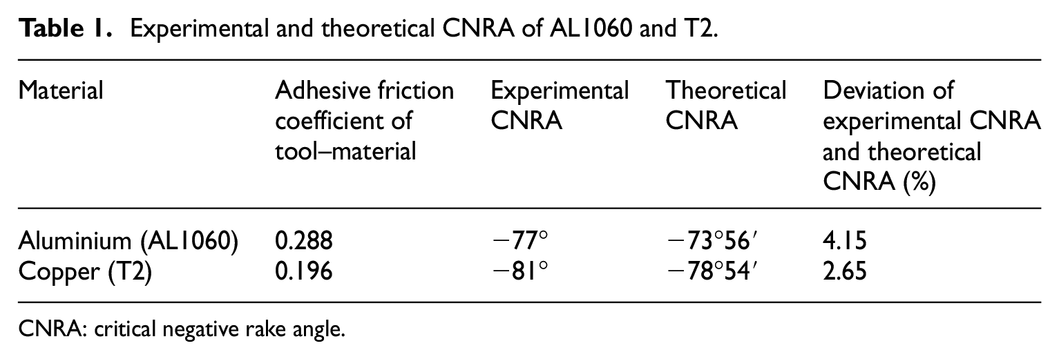
CNRA: critical negative rake angle.
As shown in Table 1, the adhesive friction coefficients of AL1060 and T2 materials are 0.288 and 0.196, respectively. The experimental CNRA are −77° and −81°, respectively. The theoretical CNRA obtained from the different friction pairs are −73°56′ (AL1060) and −78°54′ (T2). The deviation of the experimental and theoretical CNRA values were 4.15% and 2.65%, respectively. The deviation is related to many factors. Due to the use of multiple test methods, the cutting depth and cutting speed are uniformly standardized during the test, and the deviation of the test angle is far greater than that of the maximum deflection angle of the tool post of the trimming angle. Therefore, the deviation caused by the test can be neglected. As Ozturk et al. 18 and Ohbuchi et al. 21 proposed, there will be a stagnant region in front of the tool rake face cutting with a large NRA tool. The authors point that the deviation between ANRA (experimental value) and ENRA (theoretical value) of a large NRA tool is caused by the cutting edge stagnant region, and the thickness of the stagnant region will increase the value of effective CNRA. The thicker the stagnant region is, the greater the deviation between the experimental CNRA value and the theoretical CNRA value is. It can be calculated from the data in Table 1; the thickness of the stagnant region of AL1060 is 58′ greater than that of the T2 in the critical state of ploughing action. It indicates that the better the plastic and extended properties of the metal material, the thicker the stagnant region formed under the same cutting conditions.
The CNRA value determines the flow characteristics of the material, and the value will be subject to the adhesive friction performance of the friction pair. Due to the special geometrical characteristics of rounded-edge and large NRA tools, the material of the cutting edge is often oversqueezed, and the mechanical inlaying effect forms a stagnant region to obstruct the material flow. The generation of the stagnant region and its thickness value will make the friction characteristics of the cutting friction pair become complicated. At the same time, the increase in the adhesive friction coefficient between the tool and workpiece exacerbates the tool wear and shortens the service life of the tool. Therefore, the CNRA model is reliable to consider the stagnant region, and the accuracy of the model is higher through the deviation analysis of theoretical and experimental CNRA.
Surface quality
In order to further investigate the effect of the CNRA on the quality of machined surface, roughness and residual stress value of the machined surface of AL1060 were measured and analysed by different testing methods.
Surface roughness
The surface roughness of the samples processed by different rake angles is measured by an NT1100 surface roughness measuring instrument produced by an American company, VEECO, as shown in Figure 7. It can be seen from the comparison that the roughness of the machined surface becomes smaller when the rake angle of the tool decreases from −60° to −75°; the machined surface roughness increases rapidly when NRA reaches the critical value, which is close to the surface roughness of the original workpiece surface. These above phenomena show that pure ploughing and pressing effect of the CNRA on the material will not change the machined surface roughness. The quality of the machined surface will be greatly improved by both cutting and ploughing effect, and with the increase of the proportion of cutting effect, the machined surface roughness value becomes larger.

Roughness 3D drawings of the machined surface. (a) NRA: −60°, Ra: 383 nm. (b) NRA: −65°, Ra: 294 nm. (c) NRA: −70°, Ra: 206 nm. (d) NRA: −75°, Ra: 141 nm. (e) NRA: −77°, Ra: 420 nm. (f) Original workpiece surface Ra: 479 nm.
Surface residual stress
X-ray diffractometer (XRD) is used to test and analyse the surface residual stress of AL1060 processed sample. The relationship between the tool rake angle and the residual stress of the workpiece surface is shown in Figure 8 through the error analysis. The data analysis shows that the residual stress of the machined surface layer is characterized by residual compressive stress when the tool with a large NRA acts on the material. As the NRA becomes more negative within the controllable error range, the residual compressive stress value becomes larger. The overall rate of change shows an exponential increasing trend, and the residual compressive stress reaches the maximum when the tool rake angle approaches or reaches the critical value. It shows that in the role of pure ploughing of the NRA tool, the disappearance of cutting shear and the sharp increase of the contact area between the rake face and the workpiece increase the pressing effect of the cutter on the material.

Residual stress of the machined surface.
The above analysis of the surface quality of the workpiece shows that CNRA is an important parameter to the large NRA in the machining. Surface of the workpiece is characterized by a large residual compressive stress, which can greatly increase the serviceability of the workpiece when working at the critical value. At the same time, because the tool only ploughs and extrudes the material, there is no material removal effect, and the roughness of the machined surface cannot be improved. Therefore, it is necessary to determine the CRNA when the actual large NRA tool is used in micro-cutting. The actual machining will select different machining NRA values for different requirements.
Conclusion
The CNRA of large NRA tools, which determines the flow characteristics of the material, the quality of the machined surface and the worn length of the tool, is an important parameter in metal cutting with a large NRA. Therefore, based on the combination of theoretical modelling and orthogonal cutting experiment, several conclusions about the critical value of NRA can be drawn as follows:
The theoretical model of the CNRA (h1 > r) considered the stagnation region was established by the theory of minimum energy dissipation in this article and the value of CNRA was related to the adhesive friction coefficient between the tool and workpiece. By comparing with the stagnant angle model (h1 ≤ r) of Malekian et al., 7 the theoretical model had certain universality.
The CNRA (−77° and −81°, respectively) was obtained by orthogonal cutting of the plastic material AL1060 and T2 with an NRA diamond tool. The CNRA value changed the flow characteristics of the material. As the NRA became more negative, the cutting and normal force became larger, and the apparent friction coefficient tended to decrease gradually; it showed that the increase of the normal force acting on the material is more than the increase of the tangential force.
The adhesive friction coefficient increased as the plasticity and ductility of the material increased by analysis of the tool–workpiece adhesive friction coefficient. According to the error analysis, it could be seen that the deviations of AL1060 and T2 materials’ theoretical and experimental CNRA were all less than 5%, the stagnant region was the main factor leading to the deviation and the thickness of the stagnation region would increase with the growing of the deviation value. Therefore, the CNRA model established in this article was reliable considering the stagnant phenomenon.
The CNRA had a significant effect on the surface quality. As the rake angle became more negative, the surface roughness became larger and the residual compressive stress value showed an exponential increasing trend. However, the machined surface roughness corresponding to the CNRA was poor when the rake angle was near to the CNRA value, while the residual compressive stress value still increased. The analysis results showed that it was necessary to determine the CNRA value in micro-cutting with large NRA tools.
The research studies in this article indicate that the CNRA model has certain accuracy and universality, which support the theoretical and experimental foundation for solving the CNRA value in micro-cutting with large NRA tools.
Footnotes
Acknowledgements
The authors thank the anonymous reviewers for their valuable comments.
Declaration of conflicting interests
The author(s) declared no potential conflicts of interest with respect to the research, authorship and/or publication of this article.
Funding
The author(s) received the following financial support for the research, authorship and/or publication of this article: The authors would like to acknowledge the Natural Science Foundation of China (NSFC) (Grant No. 51405031, No. 51575057 and No. 51075042).