
Abstract
Field assisted sintering technologies like spark plasma sintering (FAST/SPS) are attractive alternative methods for the processing of nanocrystalline Nd–Fe–B magnets with well-pronounced anisotropic magnetic properties. This work aims to investigate the potential of hot deformation through FAST/SPS, a method commonly referred to as spark plasma texturing (SPT). SPT with its fine-tuned and closely monitored parameters of heating rate and applied uniaxial pressure has the possibility to yield further refined microstructure and reproducibility when compared to traditional hot deformation. This fine control has the potential to expand beyond the consolidation of nanocrystalline melt-spun starting powder and into other starting materials. Here, the focus is on two different routes of SPT both starting from the same commercial melt-spun Nd–Fe–B powder (Magnequench MQU-F). One deals with the SPT of semi-dense MQU-F compacts (∼70% density), while the other focuses on deformation of MQU-F fully dense compacts. Semi-dense compact SPT could lead to new routes for the consolidation of anisotropic Nd–Fe–B magnet scrap without inducing excessive grain growth, while dense compact SPT has more potential for highly textured microstructure. The best balance of properties for a magnet produced from a semi-dense compact was Br = 1.18 T, HcJ = 1203 kA m−1 and (BH)max = 249 kJ m−3, which was achieved by deforming a semi-dense compact at 800 °C applying a pressure of 100 MPa. When starting from a dense compact, the best performance was Br = 1.38 T, HcJ = 1180 kA m−1 and (BH)max = 353 kJ m−3. Here, deformation was performed at 750 °C under 70 MPa of pressure.
Introduction
Nd–Fe–B magnets play an important role in our daily life due to their widespread application in wind turbines, electric vehicles, hybrid electric vehicles, e-bikes, consumer goods, computers and green energy technologies.1,2 The weight of magnets in these applications varies from tons down to several grams. 3 The preference for using Nd–Fe–B magnets is derived from these magnets having the highest energy-product, (BH)max, at room temperature (theoretical 512 kJ·m−3) among all permanent magnet materials currently available on the market. Processing of Nd–Fe–B magnets is traditionally based on powder metallurgy. There are two main processing routes established, which differ in the kind of starting powder and either result in microcrystalline or nanocrystalline magnets.
For the manufacturing of microcrystalline Nd–Fe–B magnets, powder production starts from melting and strip casting of the alloy.3,4 The produced flakes are comminuted by hydrogen decrepitation and afterwards jet milled, resulting in a monocrystalline powder with a particle size in the range of 1–10 µm. The compaction of the green body is done by conventional powder metallurgical methods like uniaxial or cold isostatic pressing. A peculiarity of sintered magnet production is the alignment of the powder particles before or during the green body compaction by applying an external magnetic field, Hc, in the range of 10–20 kOe (1–2 T, 796–1592 kA·m−1). Finally, the magnets are sintered with a transient liquid phase under protective atmosphere at temperatures in the range of 1000–1100 °C.
For the manufacturing of nanocrystalline Nd–Fe–B magnets, different kinds of nanocrystalline starting powders can be applied, melt-spun powders,5,6 mechanically alloyed powders, 7 and hydrogenation-disproportionation-desorption-recombination (HDDR) powders.8–12 This work focuses specifically on melt-spun powder. For the specific processing issues of the other powders, we refer to the literature. In the case of melt-spinning, the Nd–Fe–B alloy containing all alloying elements is molten and ejected on a rotating metal wheel (e.g. made of molybdenum) resulting in quenched ribbons or flakes with a size in the range of several 100 µm. To ease the subsequent powder processing, the size of the flakes can be decreased by milling or crushing. Due to rapid solidification, the primary grains of the main hard magnetic Nd2Fe14B phase in the flakes remain nanocrystalline with a size in the range of 10–30 nm.13,14
Nanocrystalline Nd–Fe–B powders can be directly used in polymer bonded magnets, resulting in a good compromise of magnetic properties, diluted by the volume fraction in relation to the polymer, and costs. As an alternative, nanocrystalline Nd–Fe–B powders can be used as starting material for the manufacturing of high-performing fully dense anisotropic magnets by applying a multiple-stage production process.15–19 In principle, all kinds of nanocrystalline powders can be used as starting material, 20 but melt-spun powders have the highest potential for studying the microstructure formation as function of processing parameters and to benchmark established hot deformation technologies with field assisted deformation technologies like spark plasma texturing. This is due to starting from ultrafine, uniform primary grains. Contrarily, HDDR powders have a coarser grain structure than melt-spun ribbons and hence show greater deformation resistance during the fabrication of a textured Nd–Fe–B magnets. 21 This enhances the risk of cracking of the samples 22 and usually leads to lower texturing after hot deformation.20,23,24 As a first step of the established multi-stage production process, the powder is cold pressed into compacts. Then, the compacts are fully densified by hot pressing at temperatures in the range of 650–900 °C and a pressure of up to 300 MPa.17,18 During hot pressing, anisotropic grain growth along the a-axis of the Nd2Fe14B crystal already occurs, which becomes more pronounced with increasing temperature.6,25 In the as-hot-pressed state, the microstructure contains randomly oriented grains with a size in the range of 20–50 nm, leading to isotropic magnetic properties at this stage. As a final step, anisotropic magnetic properties are achieved by hot deformation of the hot-pressed parts either by die-upsetting (plane magnets) or hot extrusion (ring magnets). 26 A deformation degree – defined by height reduction in relation to the initial height – of up to 75% can be achieved by applying temperatures in the range of 650–900 °C and a pressure of up to 150 MPa.15,17,18,27 Deformation degree has a significant influence on magnetic behaviour. 28 As the deformation degree increases, the fibre texture also become pronounced, indicating a higher alignment of the ‘c’ crystallographic/easy magnetisation axis of the Nd–Fe–B grains along the pressure direction. This alignment leads to an increase in remanence and, consequently, energy-product. 27 On the nanoscale, anisotropic grain growth occurs resulting – in the ideal case – in plate-like grains with a width in the range of 200–500 nm and a height of 20–50 nm and fully aligned with the longest axis perpendicular to the deformation direction.
Different mechanisms have been proposed for the development of this texture, which are summarised in the manuscript of Hioki. 15 It is proposed therein that thermo-mechanical alignment of the crystal grains of Nd–Fe–B occurs at roughly 800 °C. Maintenance of temperatures above the melting point of the grain boundary phase is necessary for good formability. Even though different mechanisms of grain alignment under applied hot deformation stress are discussed in the literature, no definitive conclusion has been reached, as individual hypotheses cannot fully explain the overall observed behaviour of texture development. On the one hand, literature describes grain rotation and/or grain boundary sliding of the c-plane under the applied hot deformation stress. With further increase of temperature, this comes at the detriment of inducing abnormal grain growth.15,29,30 On the other hand, in standard hot deformation, the grain alignment starts with the melting of the grain boundary phase coupled with anisotropic grain growth and grain boundary migration. 30 Then, under an applied stress, it is hypothesised that the platelet-shaped grains further develop anisotropy through atom transfer through the liquid grain boundary phase by a pressure assisted ‘solution-precipitation creep’ mechanism. 26 Partial solution of the bulk material changes the composition of the grain boundary phase during microstructure evolution. After hot deformation, the c-axis of the platelet-shaped grains align to be parallel to the pressing direction.15,30 Another important influence factor – especially on the coercivity – is the thickness and composition of the temporarily molten grain boundary phase after its solidification. 31 Liu et al. 32 reports an increase of the coercivity with increasing thickness and Nd content of this grain boundary phase and explains this effect with an improved magnetic isolation of the grains. Similar relationship was discussed by other authors.33,34
Electric current assisted sintering (ECAS) technologies are an attractive alternative for hot deformation of nanocrystalline Nd–Fe–B magnets. It is expected that direct Joule heating of the compacts by current flow through the bulk in combination with the applied load further improves microstructure evolution. It has been demonstrated recently that there is a potential of ECAS technologies for the direct recycling of magnet scrap,35–37 which is not accessible by the established technologies mentioned above. Several ECAS technologies have been investigated for the processing of Nd–Fe–B magnets so far. In all cases, melt-spun, nanocrystalline Nd–Fe–B powders or scrap from hot-deformed magnets have been used as starting materials.
Electro discharge sintering (EDS): Leich et al. reported the production of Nd–Fe–B magnets with isotropic magnetic properties by EDS.35,38 Due to densification in milliseconds by sudden release of energy stored in a capacitor, this method is the most economical of all sintering technologies. However, achieving high microstructural homogeneity is challenging and there is a limitation of the maximum sample size. At current status of the development, the projected area is below 600 mm2.
39
Flash Spark Plasma Sintering (Flash SPS): Flash SPS is a novel method which combines the advantages of EDS and FAST/SPS. Originally developed by Grasso et al. for the densification of ceramic materials,
40
Flash SPS was adapted by Castle et al. to produce Nd–Fe–B magnets recently demonstrating well-pronounced anisotropic magnetic properties.
41
Flash SPS cycles can be conducted in a conventional FAST/SPS device. A high-power pulse of several 10 kW and a defined length (usually less than 60 s) is forced through a pre-compacted/pre-sintered sample resulting in simultaneous densification and hot deformation with large height reduction. Our recent works show that comprehensive data analysis possible in a FAST/SPS device enabled to exactly tune the crystallographic texture while keeping the grain size on the nanoscale.36,42 Both properties are prerequisite to achieve pronounced anisotropic magnetic properties. Field assisted sintering technology/spark plasma sintering (FAST/SPS) and spark plasma texturing (SPT): Several authors investigated field assisted sintering technology/spark plasma sintering (FAST/SPS) as promising alternative to hot pressing demonstrating almost full densification of Nd–Fe–B magnets.22–24,43–49 In FAST/SPS, the powder is placed in a conductive tool consisting of two punches and a die. After mounting in the FAST/SPS device, the tool is loaded by a hydraulic system and heated by direct current flow (= Joule heating). Depending on the kind of FAST/SPS device, pulsed current or constant current is used. For conductive materials – as is the case for Nd–Fe–B powders – indirect heating by thermal conduction is superimposed by direct Joule heating of the powder. In literature, FAST/SPS of Nd–Fe–B powders was usually done at temperatures in the range of 600–900 °C. For shifting the temperature to the lower bound, pressures up to 300 MPa were applied by using WC tools.
46
Due to the lack of texture development in the case of single-stage FAST/SPS, magnets with isotropic properties resulted in this case. To overcome this restriction, several attempts were reported in literature where the authors conducted die-upsetting in a FAST/SPS device as second processing stage, resulting in Nd–Fe–B magnets with anisotropic properties. This form of FAST/SPS deformation is often referred to in literature as spark plasma texturing (SPT), where a self-supporting pellet is placed within a die with a larger diameter than its own. With the application of heat and pressure, the pellet deforms, and the intention of this process is to transform the morphology of the grains into platelets through the free deformation of the pellet. Through this process, the grains grow in a layered brick form with their c-axes parallel to the applied uniaxial force.
50
In literature, information about exact tool design, deformation parameters, dimensional accuracy and microstructural homogeneity is often incomplete. Information such as heating rate,22,47,51 tool size and type,
45
powder mass,43,45 dwell time,
43
or deformation pressure
44
are often omitted from the publication. Nevertheless, there are some recent works providing full parameter sets and explanations of the process.23,24,48
This work is a collaborative effort to explore the SPT process with potential applications in both Nd–Fe–B recycling and commercial Nd–Fe–B production. Firstly, SPT was performed on a semi-dense Nd–Fe–B pre-form, similar in nature to those used in Maccari et al. and Keszler et al. for hot deformation by Flash SPS.37,42 These semi-dense Nd–Fe–B pre-forms are sintered at 500 °C via FAST/SPS prior to SPT to suppress any grain growth yet still produce a solid compact that can withstand the application of a uniaxial load. Though theoretically this temperature is too low to induce a liquid phase within Nd–Fe–B, Joule heating effects within the Nd–Fe–B powder could lead to higher temperatures at contact points between particles, as these contact points are major sources of heat production due to the breakdown of oxide layers on their surfaces.52,53 This low-temperature pre-formation step is of interest for potential future use in the direct recycling of Nd–Fe–B scrap. Just as Flash SPS was previously used as a deformation technique for anisotropic hot-deformed Nd–Fe–B scrap, the possibility exists that SPT could perform this task as well, while producing a sample with a well-deformed edge and more homogeneous performance from edge to centre of the sample.
Secondly, general SPT optimisation was performed to explore whether this approach can be a competitive, alternative method to the established texturing by die upsetting with respect to magnetic performance. Here, dense pre-forms were produced by FAST/SPS before applying SPT. Therefore, Nd–Fe–B melt-spun powder was hot-compacted into the pre-form at a temperature of 725 °C. This temperature is high enough to induce a transient liquid phase to assist in densification. 52 This FAST/SPS hot-compact was then deformed via SPT. Since the hot-compact was dense, microstructural development was expected to occur as described, for example by Hioki. 15 As discussed before, a nano-crystalline, melt-spun powder with isotropic properties is utilised as starting material for all experiments.
Experimental
Starting materials
As starting material, commercial melt-spun Nd–Fe–B powder (MQU-F, Neo Magnequench) was used (Figure 1). The coarse flakes had a size of up to 400 µm with a maximum in the range of 150–250 µm. The tapping density of the coarse flakes was around 51%, making it challenging to fill a pressing tool evenly. In this study, we omitted milling of the flakes as optional processing step, which might further enhance the tapping density. Our target was to keep the number of processing steps low and to exclude a source of possible oxygen uptake. The coarse flakes contain nanocrystalline grains with a size below 50 nm. The MQU-F powder had a nominal composition of 30.0% Nd, 5.88% Co, 0.60% Ga, 0.92% B (all values in wt-%) and Fe as balance. MQU-F has favourable hot-working properties due to its low average starting grain size, the formation of a low-melting neodymium–iron–gallium grain boundary phase, and the improvement of magnetic properties such as thermal stability and coercivity from the addition of Ga and Co.54,55 Melt-spun powders, like MQU-F, also lead to a higher degree of texture in hot-deformed fine grains when compared to mechanically alloyed or hydrogen-disproportionation-desorption-recombination (HDDR) starting material, resulting in a higher final remanence. 20 Due to the suboptimal compaction behaviour of the pure flakes, the powder had to be pre-sintered by conventional FAST/SPS for the following reasons. First, the compacts had to withstand the minimum load of 10 kN (= 32 MPa for a Ø 20 mm sample) required for operating the FAST/SPS devices used in this study. Second, pre-sintering enables to achieve a proper microstructure and grain alignment being the basis for controlled anisotropic grain growth during hot deformation as also being standard in established hot pressing. 18 Third, pre-sintering also assists in maintaining good electrical contact during the SPT process, as the compact is a solid bulk with stable particle contacts rather than a loose powder. Two strategies were pursued for pre-sintering.
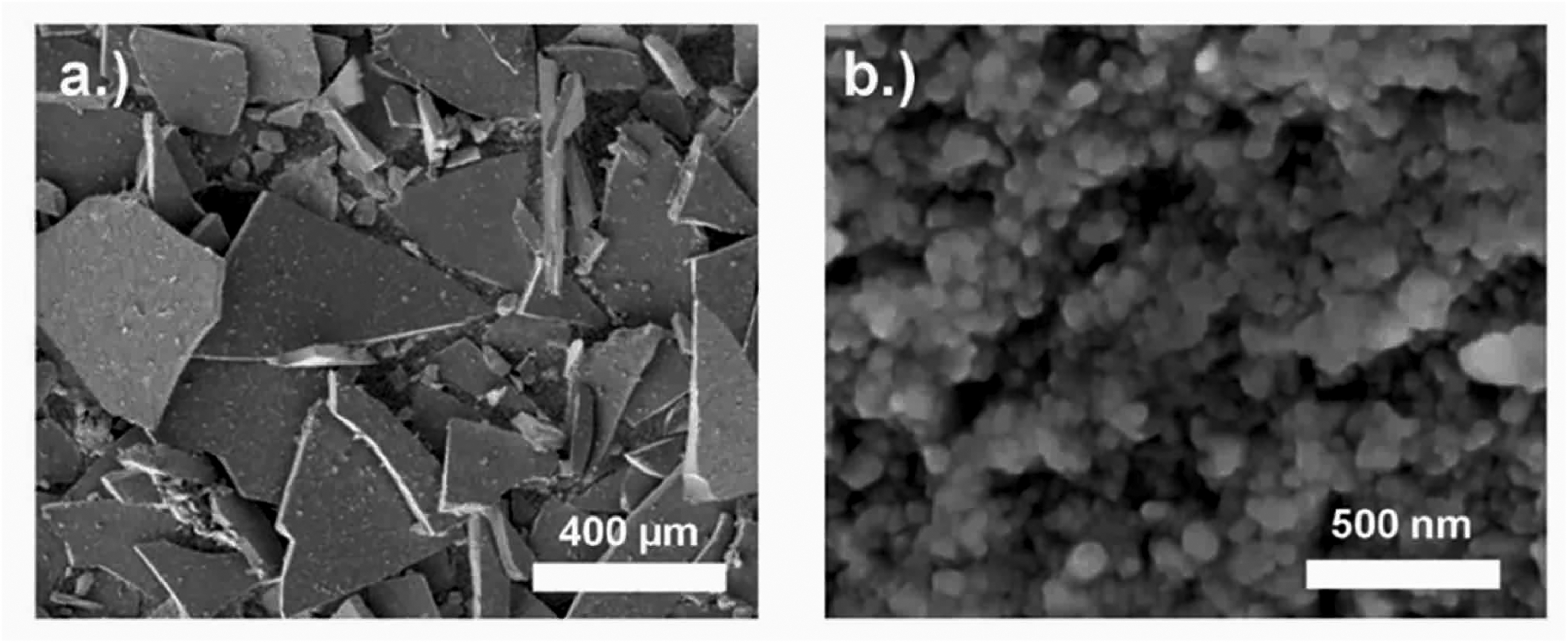
SEM-SE analysis of nanocrystalline Nd–Fe–B powder (commercial MQU-F powder from the company Neo Magnequench) made by melt-spinning and used as starting material in this study. (a) Macroscopic powder flakes. (b) Nanocrystalline Nd2Fe14B grains. The different size of the scale bars is pointed out.
Pre-sintering of semi-dense compacts for SPT
Pre-sintering of semi-dense compacts was done in a lab-scale FAST/SPS device (HP-D 5, FCT Systeme GmbH, Germany). Starting powder (15 g) was poured into a FAST/SPS graphite die (graphite type R7710, SGL Carbon GmbH, Germany) which had an internal diameter of 20 mm. Graphite foil with a thickness of 0.38 mm (type SIGRAFLEX, SGL Carbon GmbH, Germany) was used to line the die and punches in each process. FAST/SPS cycles were done with a heating rate of 100 °C min−1, a temperature of 500 °C, a dwell time of 30 s and a pressure of 50 MPa resulting in pre-sintered pellets with a height around 8 mm and a relative density in the range of 70–75%. 36 Figure 2 shows the pre-sintered form along with the stacking of the melt-spun powder particles after pre-sintering. Due to the localised heating where particles meet, sintering necks began to form, as can be seen in Figure 2(c). Further microstructural development on the granular scale was otherwise avoided by the low processing temperature.
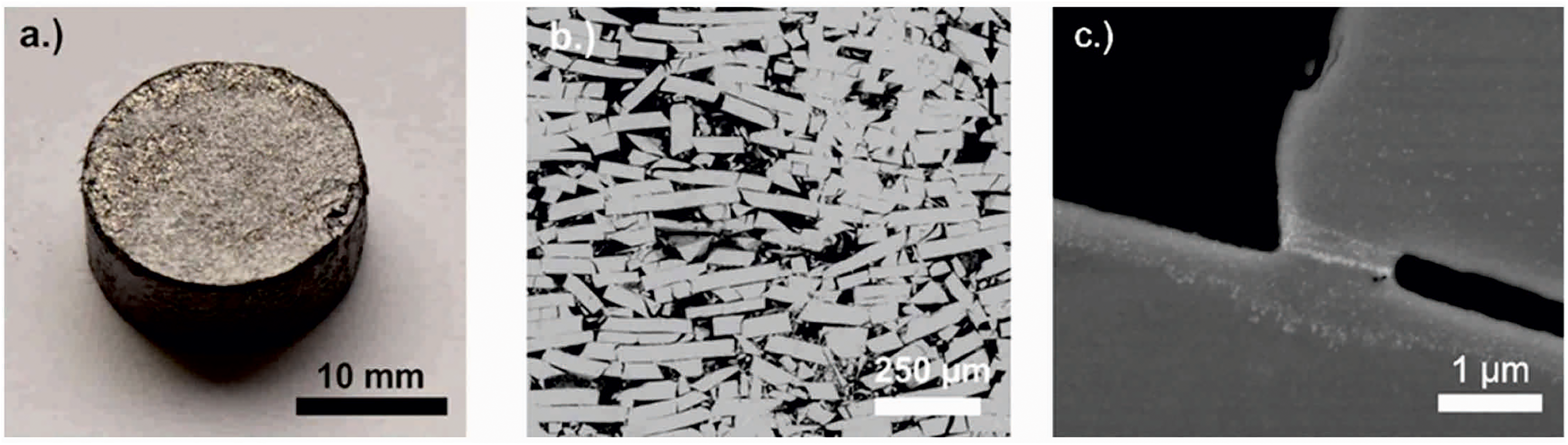
(a) Optical appearance of a Nd–Fe–B sample pre-sintered by FAST/SPS from melt-spun MQU-F powder (pre-sintering parameters 100 °C min-1, 50 MPa, 500 °C, 30 s), (b) SEM-BSE analysis of stacking of MQU-F powder within the pre-sintered compact and (c) evidence of a sintering neck likely formed due to higher heat at particle contact points.
Hot compaction of dense compacts for SPT
Hot compaction of MQU-F to dense compacts was performed in the FAST/SPS device HP-D10 (FCT Systeme GmbH, Germany), using a standard FAST/SPS graphite die (graphite type R7710, SIGRAFINE, SGL Carbon GmbH, Germany) with an inner diameter of 10 mm. A graphite foil with a thickness of 0.35 mm (type SIGRAFLEX, SGL Carbon GmbH, Germany) was inserted in the mould. Then, the mould was filled with 5 g of MQU-F powder, resulting in a 16 mm tall close-packed powder column (calculated tap density in the mould ca. 51%). Based on the experimental results obtained during the hot deformation (described in detail later in this manuscript), it was found that residual porosity of the pre-sintered samples has negative impact on the microstructure evolution. Therefore, full densification of the pre-sintered compacts was aspired in this experimental series.
Due to the limited strength of the graphite tool, a maximal pressure of 50 MPa can be applied during the process. To ensure good densification and formability through hot compaction of nanocrystalline Nd–Fe–B powder at such low pressure, elevated temperatures are usually required, higher than the melting point of the grain boundary phase. However, the temperature should be kept below 800 °C, as heat excess might trigger the abnormal grain growth, as shown again by Hioki. 15 To define the optimal temperature, a simple displacement test was carried out, where hot compaction was performed under continuous heating up to 750 °C, a heating rate of 75 °C min−1 and a contact pressure of 38 MPa (3 kN). As it can be seen in Figure 3(a), the optimal temperature lies in the range 650 to 750 °C, where the grain boundary phase is molten. There, a transient liquid phase forms and acts as a lubricant supporting the densification and alignment process. 52 Based on those results, it was decided to perform the hot compaction process at 700 °C with ramping rate of 75 °C min−1. During the heating step, a constant pressure of 38 MPa was applied and increased to 50 MPa during the dwell time of 60 s at 700 °C. As it can be seen in Figure 3(b), this temperature was not high enough to complete the densification process and the resulting sample has ca. 10% residual porosity (confirmed by a density measurement). Therefore, the compaction temperature was increased to 725 °C, while all other processing parameters were kept the same. The sample obtained at 725 °C is fully dense with no grain coarsening and misalignment visible, and the isotropic nanocrystalline microstructure is preserved (Figure 3(c)). Magnetic measurements (Figure 3(d)) confirm that the soft magnetic phase in the initial MQU-F powder is fully transformed after the hot compaction and the hot compacted sample have isotropic nanocrystalline microstructure.
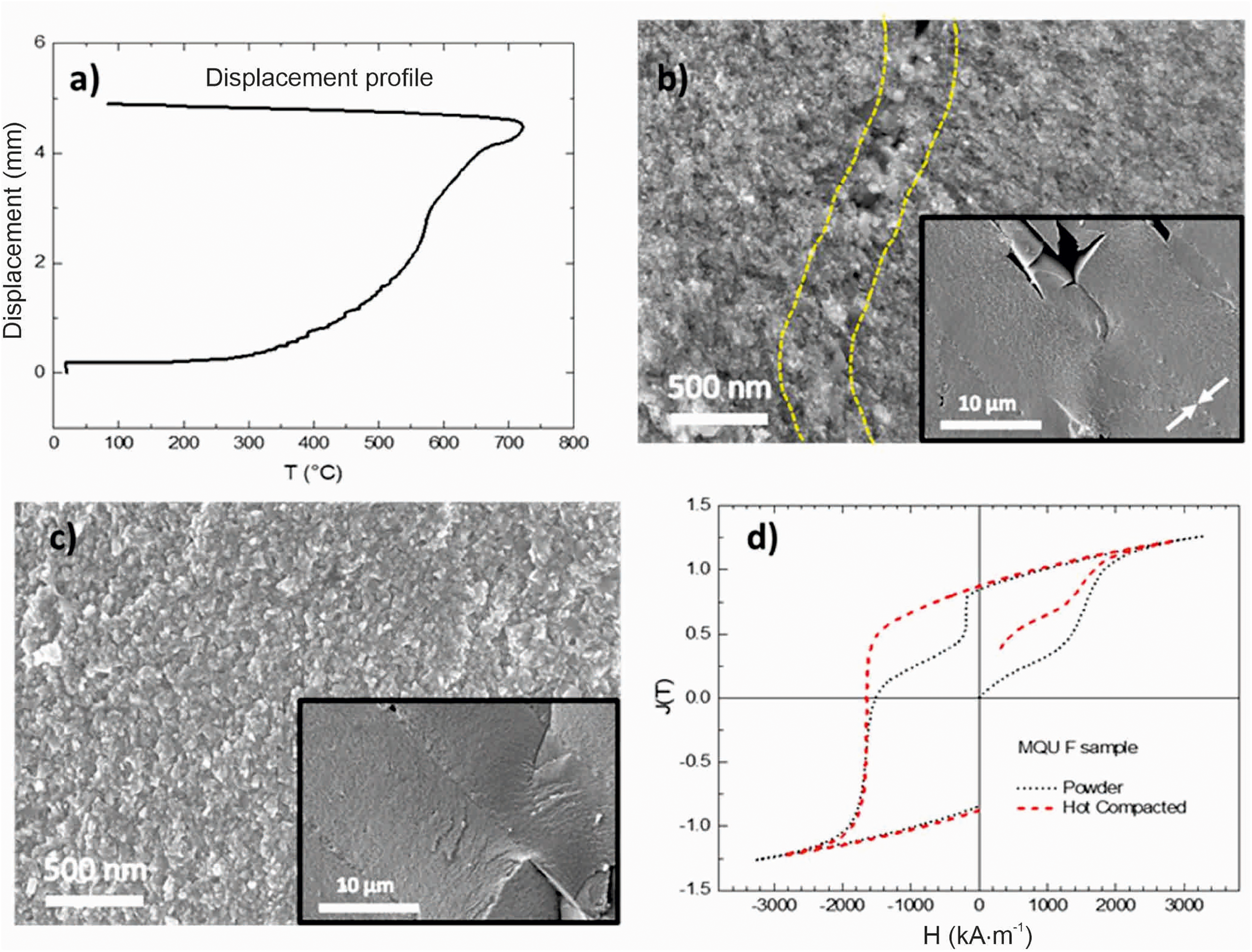
(a) Displacement profile of a test sample, compacted under 38 MPa as described in the main text. (b, c) SEM-SE micrographs of the fracture surface of a Nd–Fe–B sample pre-sintered by FAST/SPS from melt-spun MQU-F powder processed with heating rate of 75 °C min−1, a pressure of 45 MPa and a dwelling time of 60 s at maximum temperature: at 700 °C (b), the sample has 90% of the theoretical density, dotted line indicates the areas where porosity is visible; at 725 °C (c), the sample has >99% of the theoretical density, all ribbons are aligned, no grain coarsening and misalignment is visible and isotropic nanocrystalline microstructure is preserved. (d) Magnetic properties of the MQU-F powder as loose powder and as hot compacted at 725 °C.
Based on these results, the hot-compaction temperature was chosen to be 725 °C. The optimal parameters for the FAST/SPS hot-compaction cycle were selected as follows: The contact pressure of 38 MPa (3 kN) was applied while the sample was heated up to 725 °C with heating rate of 75 °C min−1. During a dwell period of 60 s, the pressure was increased from 38 to 45 MPa (3.9 kN). After processing, the height of the hot-compacted pellets was found to be ca. 8 mm, and a density of 100% was measured by the Archimedes method.
Hot deformation of semi-dense compacts via SPT
SPT of the semi-dense compacts was performed to initiate anisotropic grain growth by rapid heating to deformation temperature under the pre-load required for operating the FAST/SPS device (10 kN). After achieving the aspired deformation temperature, the deformation load was applied, which varied between 50 and 500 MPa, followed by a short dwell time of 10 s. A specific focus of this experimental series was to investigate if high pressure supports the formation of pronounced microstructural texture, even in a semi-dense compact. In this experimental series, Ø 20 mm samples pre-sintered at 500 °C were placed in a Ø 30 mm FAST/SPS tool, which was lined with a 0.38 mm thick graphite foil (type SIGRAFLEX, SGL Carbon GmbH, Germany). For the pressure of 50 MPa, the tool was made of graphite (graphite type R7710, SGL Carbon GmbH, Germany). For pressures > 50 MPa, a Ø 30 mm tool made of the Mo-based alloy TZM (Plansee, Reutte, Austria) was used. The respective tool with the sample was mounted in the hybrid FAST/SPS device (H-HP-D25 SD/FL/MoSi, FCT Systeme GmbH, Germany) and the pre-load of 10 kN (= 32 MPa for a Ø 20 mm sample) was applied. Then the sample was heated with a defined heating rate of 100 °C min−1 to the aspired deformation temperature. When achieving the temperature, the load was increased with a rate of approximately 32 kN·min−1 to the aspired value. Then, after a constant holding time of 10 s, the sample was furnace cooled and the pressure released. Hot deformation of pre-sintered samples via FAST/SPS was carried out at different temperatures, heating rates and pressures. In all cases, sample diameter after deformation reached 30 mm, so wall friction due to the contact with the die might have influenced the height reduction in the final stage of deformation Table 1 summarises the various parameter sets. In the T-series (T700-50, T750-50, T800-50), the hot deformation temperature was varied to 700, 750 and 800 °C, while the pressure of 50 MPa was kept constant. In the P-series, the pressure was varied to 100, 200 and 500 MPa at a constant temperature of 800 °C. These temperatures were chosen based on our former Flash SPS experiments, from which the 35 kW power pulse would lead to temperatures 800 °C or higher during Nd–Fe–B deformation.36,37,42
FAST/SPS parameters used for hot deformation of porous Nd–Fe–B samples (pre-sintering parameters 500 °C, 50 MPa, 10 min).
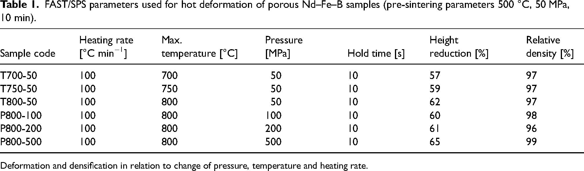
Deformation and densification in relation to change of pressure, temperature and heating rate.
Hot deformation of dense compacts via SPT
In parallel to the SPT deformation of semi-dense compacts, SPT deformation of dense compacts was performed. This was done to mirror the traditional die upsetting process and determine the viability of SPT as an alternative form of hot deformation. The samples were hot compacted by FAST/SPS using the optimised parameters as described in Section 2.1: 725 °C and 45 MPa pressure resulting in the aspired dense compact with suppressed grain growth. Figure 4(a) shows a representative microstructure of a sample compacted under these conditions. For SPT, the Ø 10 mm samples were placed in a Ø 20 mm graphite tool (graphite type R7710, SIGRAFINE, SGL Carbon GmbH, Germany). Prior the SPT hot deformation, the hot compacted samples were sandblasted and sharp edges were removed to avoid damaging of the graphite pressing tools (Figure 4(b)). SPT hot deformation was carried out in the FAST/SPS device HP-D10 (FCT Systeme GmbH, Germany). A graphite foil (SGL Carbon, SIGRAFEX) with a thickness of 0.35 mm with an additional centering ring made of the same graphite foil. This was used to ensure the central placement of the specimen, guaranteeing homogeneous deformation. Differences in die choice and size reflect the tools available to the labs performing the experiments.
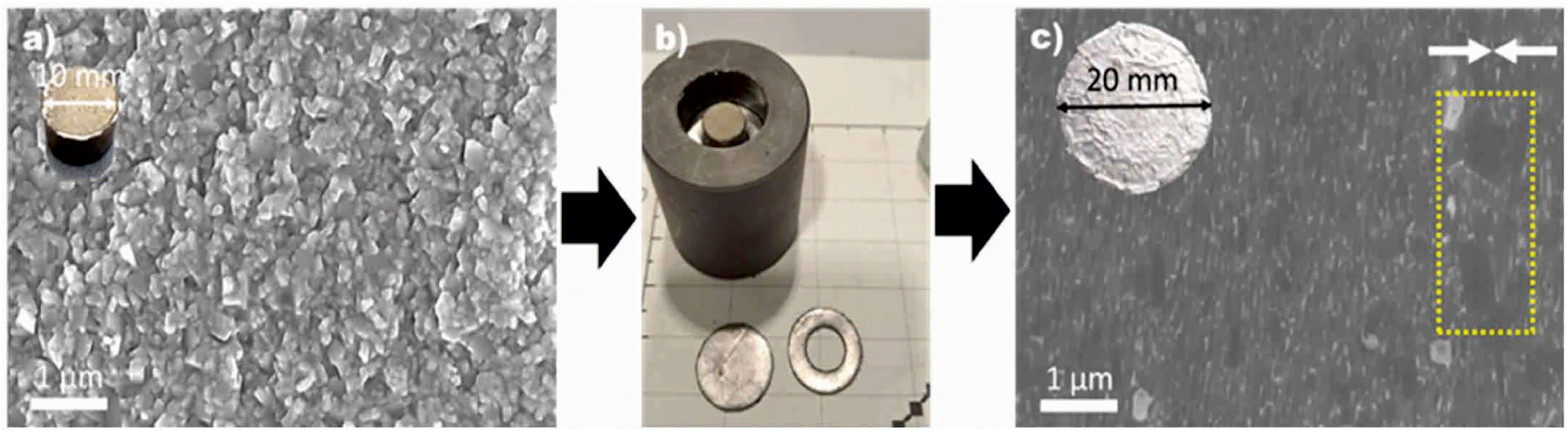
Overview of the SPT hot deformation process starting with (a) SEM-SE image of a 10-mm dense hot compacted pellet with isotropic nanograin microstructure; (b) centering the pellet in a 20-mm graphite die; (c) SEM-SE image of a 20-mm hot deformed sample (parameters: 750 °C, 70 MPa, 60 s, sample code HDS 701) with anisotropic nanograined microstructure (grain growth can be observed in the area marked by the yellow dotted line).
The processing parameters for the hot deformation step were optimised aiming to obtain a well-pronounced, fibre- or brick-like texture while simultaneously avoiding abnormal/excessive grain growth. Based on the work of Sawatzki, 56 the deformation temperature was set to be 750 °C (25 °C above the compaction temperature). The pre-load of 3 kN (minimum required for the device) was applied, during which the sample was heated up to 600 °C with a heating rate of 75 °C min−1. During the next step in the cycle, the sample was heated up to 725–750 °C with 50–100 °C min−1, and pressure was increased to 50–80 MPa. The pressure was maintained at its maximum during the dwell time of 60 s at the maximum temperature of 725–750 °C, which was followed by cooling, in which the power was switched off (see Table 2).
FAST/SPS parameters investigated for the hot deformation of almost dense pre-sintered Nd–Fe–B compacts (pre-sintering parameters 725 °C, 45 MPa, 60 s).
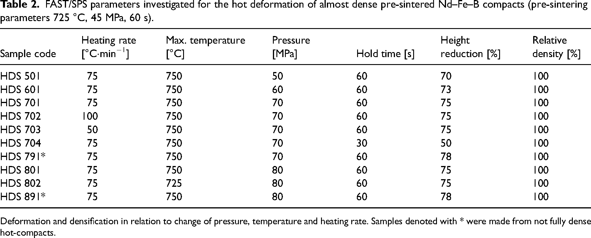
Deformation and densification in relation to change of pressure, temperature and heating rate. Samples denoted with * were made from not fully dense hot-compacts.
Characterisation methods
The relative density was calculated based on the Archimedes principle (Sartorius Quintix224-1CEU balance with YDK03 option). For the calculation, a theoretical density of 7.55 g cm−3 was used. Scanning electron microscopy (SEM) with a FEG-SEM JEOL JSM-7600 device (JEOL, Japan) and a Zeiss Merlin Field Emission Scanning Electron Microscope FEG-SEM (Carl Zeiss Microscopy GmbH) were used in back scattered electron (BSE) and secondary electron (SE) mode to characterise the phase distribution and microstructure depending on the processing conditions. Before microstructure characterisation, all samples were broken into two halves. For investigation of microstructure on larger scale regarding the grain size, grain morphology and the distribution of Nd-rich phase, one half was embedded in epoxy resin, ground with silicon carbide emery paper and then polished with water-free diamond suspensions down to 0.25 µm. The fractured surface of the other half was used for characterisation of the primary nanocrystalline grains. In the case of doing SPT with semi-dense MQU-F samples, half of the deformed samples was reserved for magnetic characterisation, which was done using a Permagraph C-300 system (MAGNET-PHYSIK Dr Steingroever GmbH, Köln, Germany). In the case of doing SPT with dense MQU-F samples, rectangular specimens (1 × 1 × 2 mm3) were cut from the sample for magnetic characterisation. Two specimens were cut form each sample: one from the centre and one from the edge. The magnetisation of the samples was measured at room temperature using a VSM-PPMS 14 system (Quantum Design). The obtained isothermal magnetisation data were then recalculated with respect to the shape to account for the demagnetisation factor.
Results
Table 3 summarises the magnetic properties remanence Br, coercivity HcJ, and energy-product (BH)max of Nd–Fe–B magnets processed by the different field assisted sintering technologies starting from melt-spun powders. For benchmark, results from our former study 36 and related results from literature were included. It is to be noted that, in the literature, MQU-F was not consistently the starting powder. Nevertheless, trends of how field assisted sintering parameters influence final microstructure and magnetic properties are obvious, enabling reliable conclusions about how to further optimise these technologies in future. As reference, magnetic properties of an MQU-F based die-upset magnet from a commercial water pump from the company WILO is considered as well. For exceeding the current industrial standard of anisotropic Nd–Fe–B magnets made by WILO, magnets should combine a coercivity higher than 1300 kA m−1 and a remanence higher than 1.3 T.
Height reduction, coercivity HcJ, remanence Br and energy product (BH)max of Nd–Fe–B magnets processed by different field assisted sintering technologies.
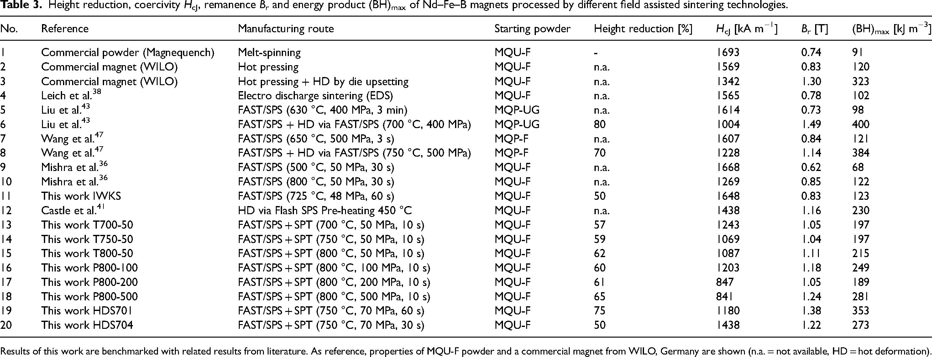
Results of this work are benchmarked with related results from literature. As reference, properties of MQU-F powder and a commercial magnet from WILO, Germany are shown (n.a. = not available, HD = hot deformation).
SPT of semi-dense compacts
As expected, densification improved with increase of temperature and increase of pressure (see Table 3). The lowest height reduction of 57% occurred with sample T700-50, which had a maximum temperature of 700 °C. Since higher deformation degrees were obtained at 800 °C compared to 700 and 750 °C – with sample T800-50 obtaining the highest deformation of 62% –, further deformation studies with varying pressure (100, 200, 500 MPa) were carried out at this temperature. Figure 5 shows the related deformation curves for the case of doing the main deformation step with a pressure of either 100 MPa (Figure 5(a)) or 500 MPa (Figure 5(b)). With increase of pressure, the height reduction increased between P800-100 and P800-500, from 60 to 65% (Table 3). The black line in the graphs shows the relative movement of the punch along with the deformation process. Deformation starts already under the pre-load at a temperature of around 500 °C. When exceeding a temperature of around 650 °C, deformation stops at a height reduction of around 50%. The plateau of the deformation curve indicates the deformation of the samples to a degree, where contact to die walls and onset of wall friction appeared. When further increasing the load, deformation proceeds, but at a lower rate.
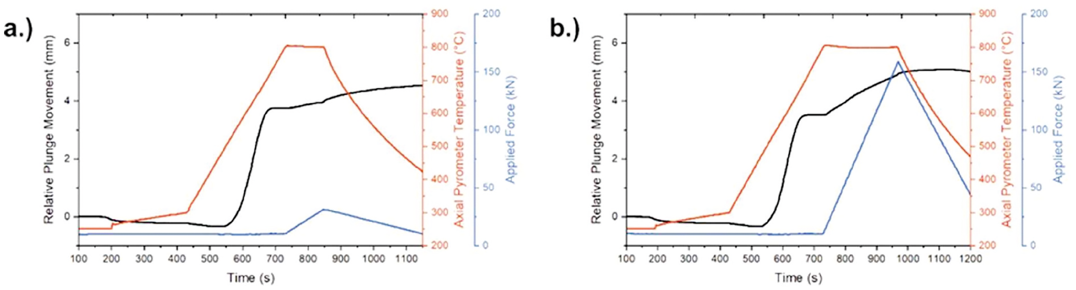
Hot deformation of pre-sintered, porous Nd–Fe–B samples (500 °C, 50 MPa, 30 s) via FAST/SPS. Pre-heating with 100 °C min−1 to 800 °C and pre-loading with 32 MPa before applying the main pressure of (a) 100 MPa (P800-100) and (b) 500 MPa (P800-500). The pressure is related to the initial sample diameter of 20 mm.
In this experimental approach, the highest Br value 1.24 T was obtained from the sample P800-500 with the maximum applied pressure of 500 MPa. Comparisons of J-H curves can be seen in Figure 6. In addition, the highest density and the largest height reduction were obtained as well. This result indicates that in general hot deformation at high pressure is advantageous for texturing the grains, therefore achieving pronounced anisotropic magnetic properties. Similar trends were observed in the literature.43,47 Nevertheless, heating with 100 °C min−1 to the aspired deformation temperature followed by another dwell time at this temperature until the main deformation load is achieved took obviously too long to reliable avoid onset of anomalous grain growth. This assumption is confirmed within the given microstructures (Figure 7). Even after the deformation step, clear boundaries of the starting MQU-F powder flakes are visible in the form of bright Nd-rich outlines. Large amounts of anomalous grains with sizes in the several micrometer ranges are a clear indicator for explaining the low coercivity values. Moreover, energy dispersive X-ray analysis of samples similarly deformed via flash SPS have shown that the large grey grains are a Nd2(Fe,Co)14B phase, despite the small changes in the BSE contrast. 37 It is interesting to note that at a given temperature (800 °C) grain growth becomes more enhanced at the higher pressure. For taking advantage of high pressure and, at the same time, avoiding anomalous grain growth, direct application of the high loads seems to be the preferred option, but sufficient stability of the pre-sintered, porous compacts is questionable in this case. Additional improvements can be made through the tailoring of deformation speeds to avoid crack formation in the final sample. 54 The best combination of properties can be seen in sample P800-100 (HcJ = 1203 kA m−1, Br = 1.18 T, (BH)max = 249 kJ m−3). This is likely due to the combination of the temperature being optimal for anisotropic grain development among the melted grain boundary phase, as stated by Hioki. 15 However, as mentioned before, Joule heating hot spots at particle contact points could lead to excessive grain growth – therefore, surface contact of the MQU-F particles at the setpoint temperature of 800 °C likely caused undesired grain growth and negatively affected coercivity. Other possible reasons for this effect are the limited control of sample temperature especially at the onset of hot deformation, which might be coupled with overheating, or enhanced solution-precipitation at higher pressure. The melting of the Nd-rich grain boundary phase, along with the simultaneous application of uniaxial pressure, could have forced a Nd-rich phase to be squeezed into the gaps between particles, causing phase segregation. 57 Despite the excessive grain growth, sample P800-500 still achieved the highest (BH)max, 281 kJ m−3, of all semi-dense deformed samples, due to its density and texture influencing its Br. The additional pressure in the samples of P800-200 and P800-500 likely led to greater mass transfer and thus more excessive grain growth, despite the higher pressure leading to a more optimal texture.
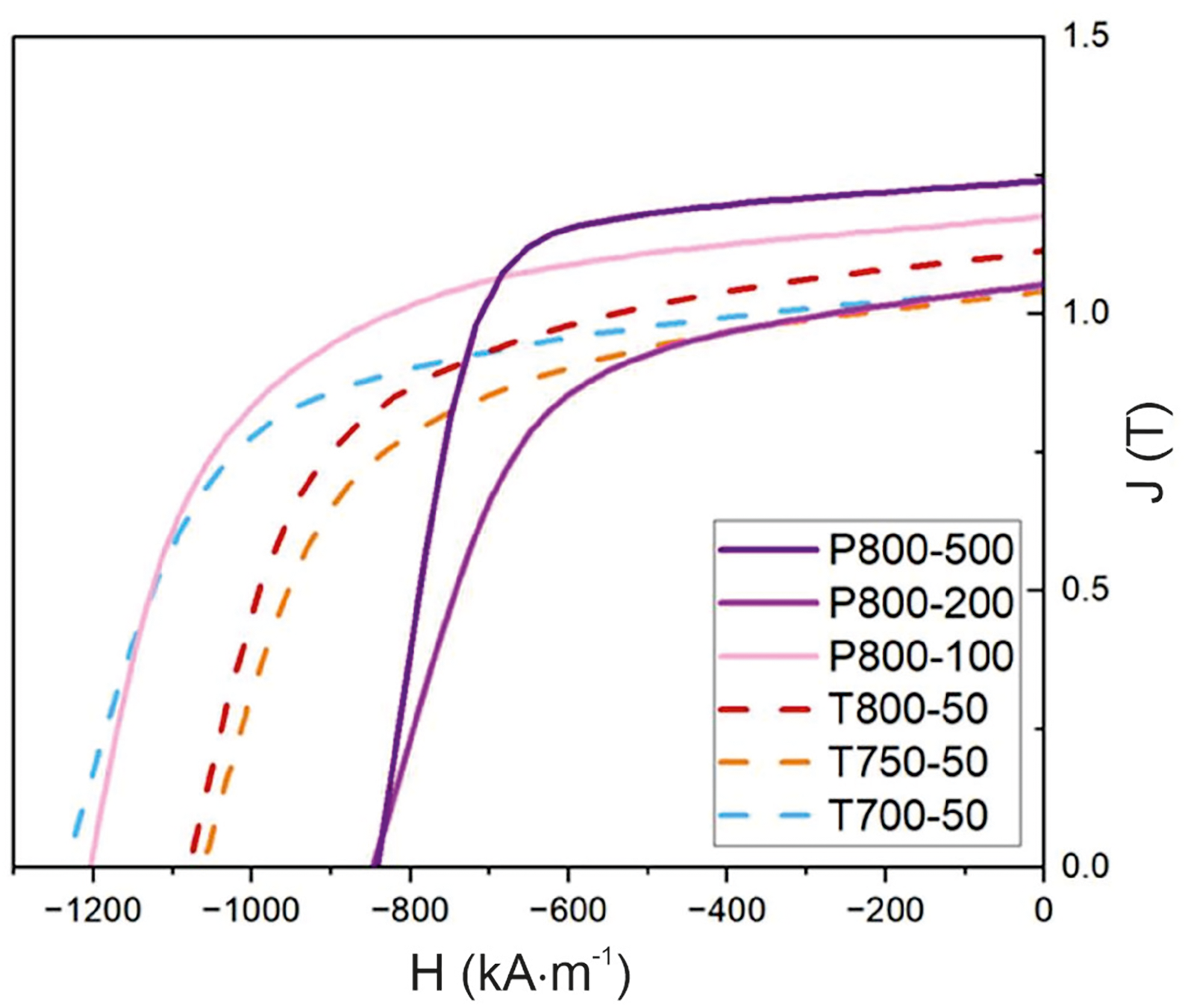
Magnetisation curves of the samples P800-100, P800-200 and P800-500, P800-500, T800-50, T750-50 and T700-50.
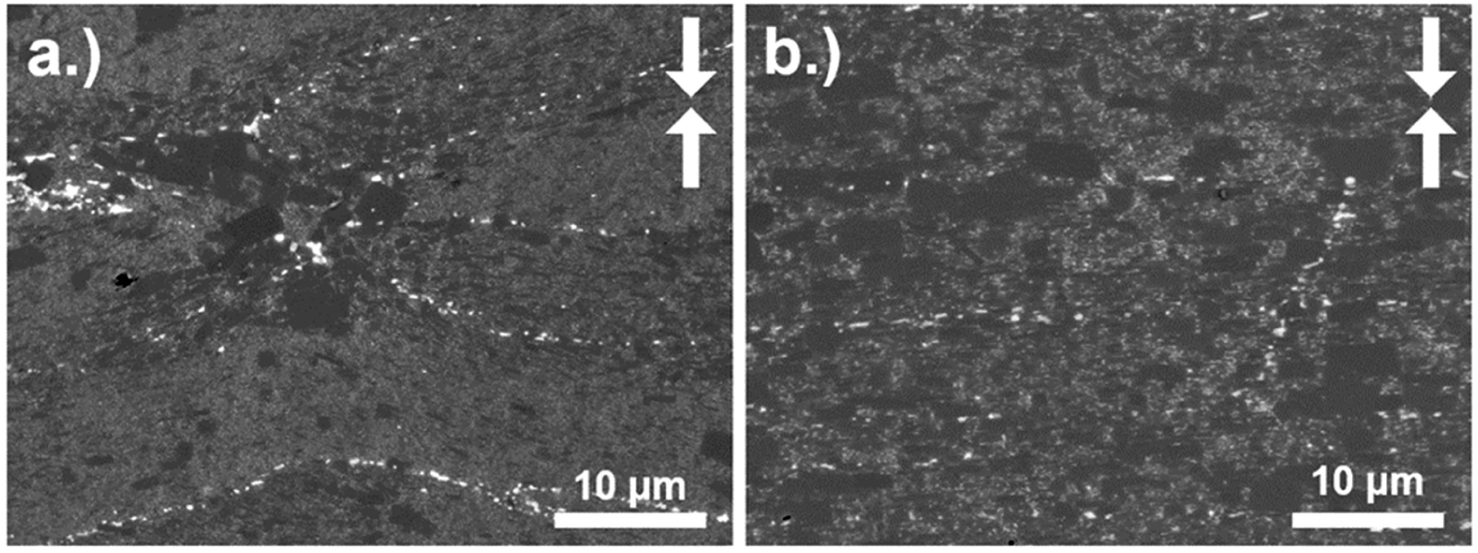
SEM-BSE cross-sections of SPT samples deformed at given heating rate (100 °C min−1) and temperature (800 °C), but different maximum pressure (a) 100 MPa (P800-100) and (b) 500 MPa (P800-500). The sample P800-100 deformed at 100 MPa displays significantly less alignment than the sample P800-500 deformed at 500 MPa. The sample P800-500 also displays much larger grains. The pressing direction is marked with white arrows.
SPT of dense compacts
Different from the previous section, the deformation is performed starting from fully dense compacts. The sample HDS501 produced with a maximum temperature of 750 °C and maximum pressure of 50 MPa had a final diameter of 19 mm. Therefore, the sample did not fully deform to the 20 mm diameter of the die used for deformation. This inadequate deformation caused the sample to not be well-deformed at the edge, where cracks were visible (not shown here). Consequently, the degree of alignment was inhomogeneous at the outer part of the sample. Contrarily, a homogeneous microstructure was observed in the centre. To complete the deformation and improve the microstructure with respect to the texture, the pressure during the dwell time of 60 s at 750 °C was further increased to 60 MPa (sample series HDS60x), 70 MPa (sample series HDS70x) and 80 MPa (sample series HDS80x), while keeping the cooling conditions constant.
By increasing the applied pressure, a significant improvement on the alignment was obtained, however grain growth was observed. This is in agreement with the experimental series SPT of semi-dense Nd–Fe–B compacts in section ‘SPT of semi-dense compacts’, though the scale of pressure increase was in the range of the tens of MPa as opposed to the hundreds. Likely grain growth could be attributed to increased mass transfer along the liquified Nd-rich grain boundary phase under increased pressure. As summarised in Table 2, further deformation experiments were done by varying the heating rate (50–100 °C min−1) and the dwelling temperature (30 s and 60 s). In terms of observed microstructures, the best results were obtained for the sample HDS 701 with the heating rate of 75 °C min−1, a pressure of 70 MPa and a dwell time of 60 s at 750 °C. Under these conditions, a nano grained microstructure with well aligned grains was obtained (see Figures 4(c) and 9(a)).
This deformation of dense compacts is an approach is in accordance with established magnet production by hot pressing and die-upsetting. 18 Figure 8 shows the FAST/SPS cycles used for production of hot-compacted, dense parts (Figure 8(a)) and the sample HDS 701 hot-deformed by SPT (Figure 8(b)). For the SPT hot deformation, contact pressure of 10 MPa (calculated for the 20 mm die) was applied and temperature was increased up to 750 °C with heating rate of 75 °C min−1. Once the sample temperature reached 600°C, pressure and temperature were increased simultaneously until reaching 50 MPa at 750 °C. The pressure was further increased to 70 MPa during the 60 s dwelling step at 750 °C (See Figure 8).
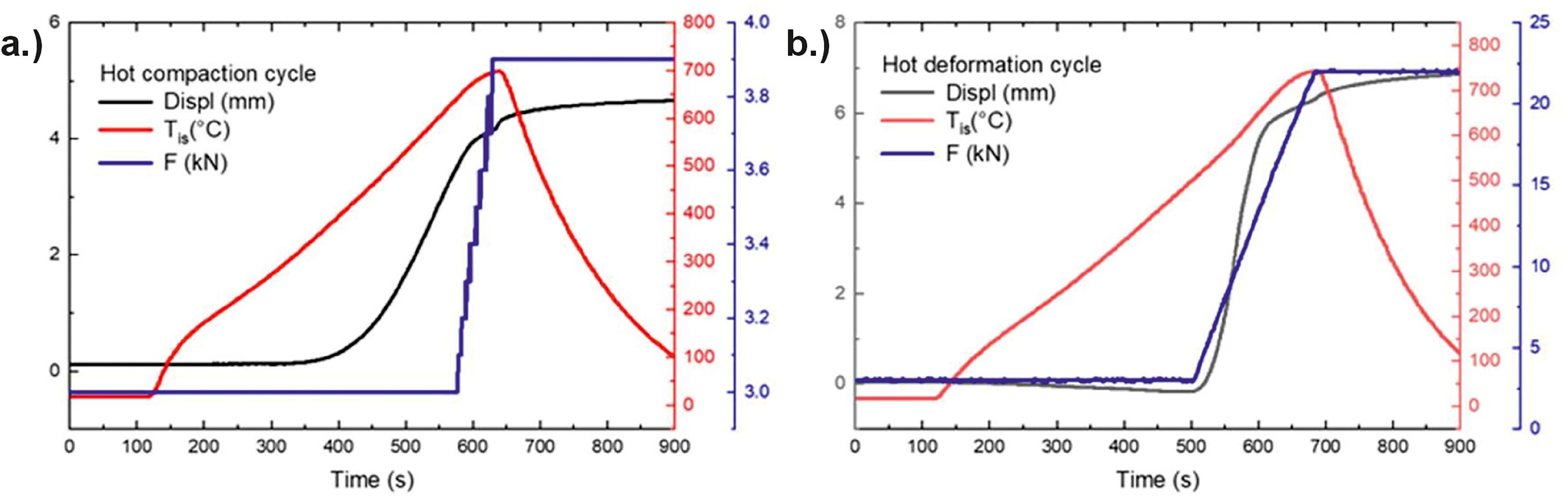
(a) Hot compaction via FAST/SPS resulting in a dense sample (725 °C, 48 MPa, 60 s). (b) Hot deformation (spark plasma texturing) of dense Nd–Fe–B samples: pre-heating with 75 °C min−1 to 600 °C and pre-loading with 10 MPa before applying the main pressure of 70 MPa and temperature of 750 °C (sample HDS 701).
The pressure during the dwelling step was varied between 50 and 80 MPa in order to obtain better deformation and alignment of the nanocrystalline grains as shown in Figure 4. Based on the obtained results, it was found that the pressure of 50 MPa (sample HDS 501) is not enough to fulfil the deformation (only 70% height reduction instead of the aimed 75%). The sample obtained at 50 MPa has well-aligned microstructure in the centre, but high degree of misalignment and cracks in the outer edge area. The sample HDS 601 obtained with 60 MPa applied pressure has 73% height reduction and well-aligned microstructure in most of the volume with small misalignment areas close to the edge. The sample HDS 701 obtained with 70 MPa applied pressure has 75% height reduction and well-aligned microstructure in the whole sample volume, while the grain growth remains on a low level (see Figure 9(a)).
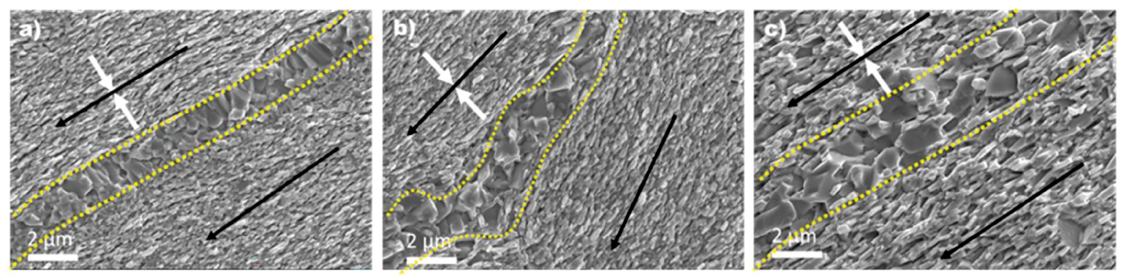
Influence of the hot compacted sample density on the microstructures (SEM-SE) of hot deformed sample: (a) dense hot compacted sample HDS 701 hot deformed at 750 °C, 70 MPa; (b) 90% dense hot compacted sample HDS 791 hot deformed at 750 °C, 70 MPa; (c) 90% dense hot compacted sample HDS 891 hot deformed at 750 °C, 80 MPa; The white arrows indicate the pressing direction. Black arrows indicate the alignment direction – perpendicular to the pressure axis. The dotted lines indicate the area of grain growth.
To understand the correlation between the initial sample density and the resulting microstructure, hot deformation was also performed on a pre-sintered sample with only 90% density (see related microstructure before hot deformation in Figure 3(a). As reference, the microstructure of sample HDS 701 hot deformed at 750 °C, 70 MPa starting from a dense, semi-finished part is shown in Figure 9(a). In sample HDS 701, the alignment of the nanocrystalline grains (indicated by black arrows) is perpendicular to the pressing direction (indicated by white arrows) and parallel in both neighbouring flakes. Grain growth is observed in the boundary area of former powder flakes as indicated by dotted lines. Figure 9(b) represents the microstructure of the sample HDS 791 hot deformed with the same parameters as sample HDS 701 (750 °C, 70 MPa), but starting from a semi-finished part with a density of only 90%. The two neighbouring flakes have well aligned nanocrystalline grains, however these are not aligned perpendicular to the pressing direction and parallel to each other. It is possible that, during the deformation process, the flakes adjacent to the pores do not rotate and slide parallel to the other flakes as described above, but preferably slide into the empty pore space with a rather random orientation. This can explain why optimal alignment is not seen in SPT samples of semi-dense compacts at similar deformation pressures, as described in the previous section ‘SPT of semi-dense compacts’. In an attempt to improve the orientation of such flakes, the hot compacted sample HDS 891 with 90% density was hot deformed at 750 °C, 80 MPa, and the obtained microstructure is shown in Figure 9(c). As it can be seen, the alignment of the nanocrystalline grains in the two neighbouring flakes is again parallel to each other and perpendicular to the pressing direction. Figure 10 is provided to show a contrasting situation, where grains are misaligned, with some being parallel and some being perpendicular to the pressing direction. However, the flake boundary area is now broader and the grains are also bigger due to the ongoing grain growth processes. The pressure increment of 10 MPa has resulted in a better alignment by mitigating the misorientation caused by pore/void filling during deformation at lower pressure. This outcome indicates that the initial porosity in the hot compact (90% density in this case) must be taken into account in the optimisation parameters.
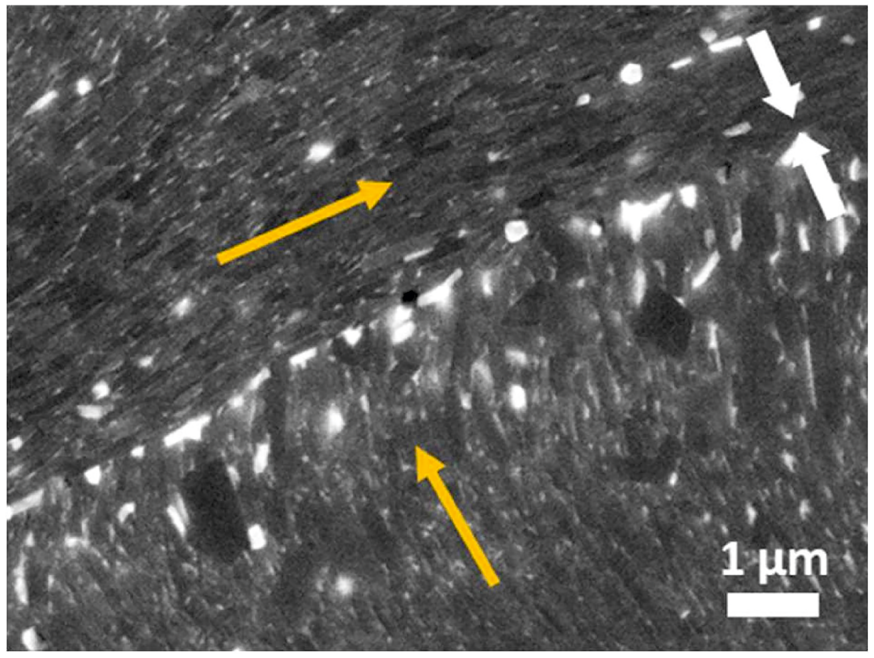
BSE-SEM image of Nd–Fe–B after hot deformation showing former two adjacent powder particles and how the grain alignment (orange arrows) is related to the applied pressure direction (white arrows).
The sample HDS 801 obtained with 80 MPa applied pressure at 750 °C shows a well-aligned but coarsened microstructure due to accelerated grain growth at the interparticle interface possibly enhanced by the improved grains contact and thermal conductivity (see Figure 11(a)). Sample HDS 802 hot deformed with 80 MPa at lower temperature demonstrates that grain growth can be controlled by the proper selection of the processing parameters (see Figure 11(b)). In agreement with the SPT of semi-finished, dense Nd–Fe–B compacts, there seems to be an applied pressure range of around 80–100 MPa and a maximum temperature of 750–800 °C where texturing occurs without excessive grain growth, leading to the best combination of HcJ and Br. When further increasing the pressure at these temperatures, however, is expected to cause excessive grain growth despite the development of well-aligned texture as indicated by the results in section ‘SPT of semi-dense compacts’.
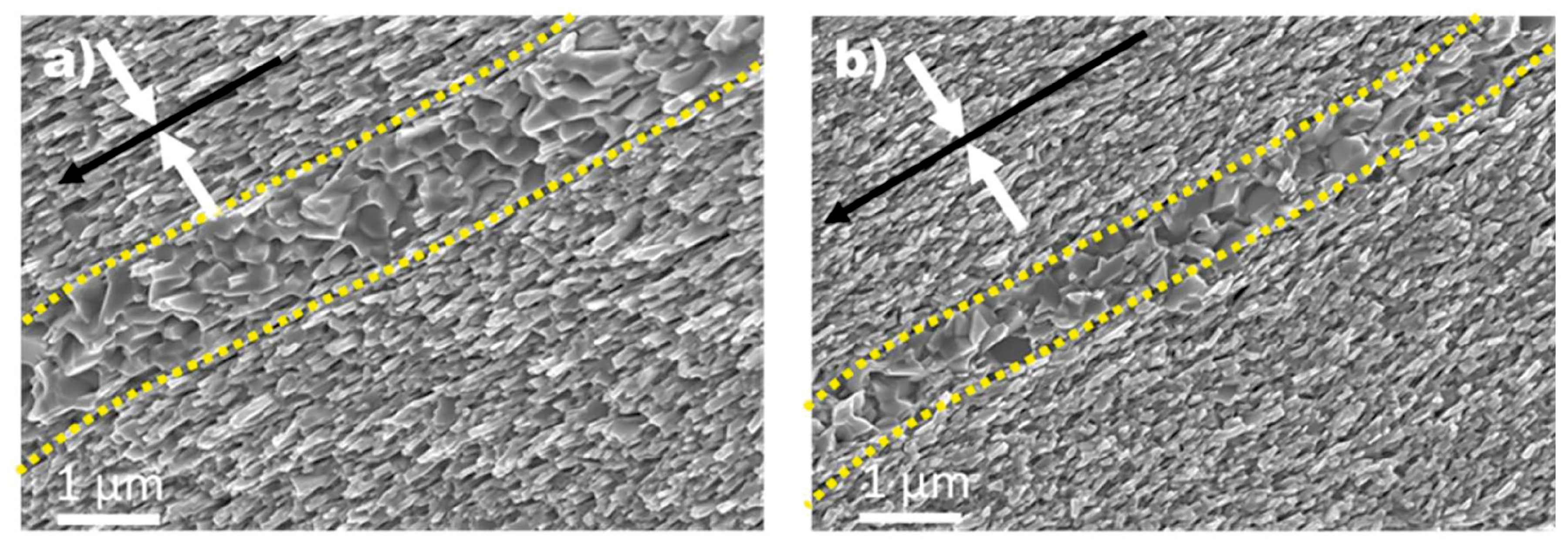
Influence of the deformation pressure on the microstructures (SEM-SE) of hot deformed sample: (a) sample HDS 801 hot deformed at 750 °C, 80 MPa; (b) sample HDS 802 hot deformed at 725 °C, 80 MPa. The white arrows indicate the pressing direction. Black arrows indicate the alignment direction – perpendicular to the pressure axis. The dotted lines indicate the area of grain coarsening.
Figure 12 shows the magnetic properties of the best performing sample HDS701, which has a remanence of 1.38 T and was obtained at a deformation temperature of 750 °C under applied pressure of 70 MPa and ramping speed of 75 °C min−1. For this sample, magnetic measurements were performed on rectangular specimens cut from centre and edge of the sample. Almost full coincidence of both curves confirms the high homogeneity of the sample. HDS 704 also had a notable remanence of 1.22 T and coercivity of 1438 kA m−1. While HDS 704 had a lower remanence than HDS 701, it displayed a higher coercivity. The increase in dwell time between HDS 704 and HDS 701 likely led to a combination of improved texture, thus an increase in remanence and grain growth, but a hinderance in coercivity.
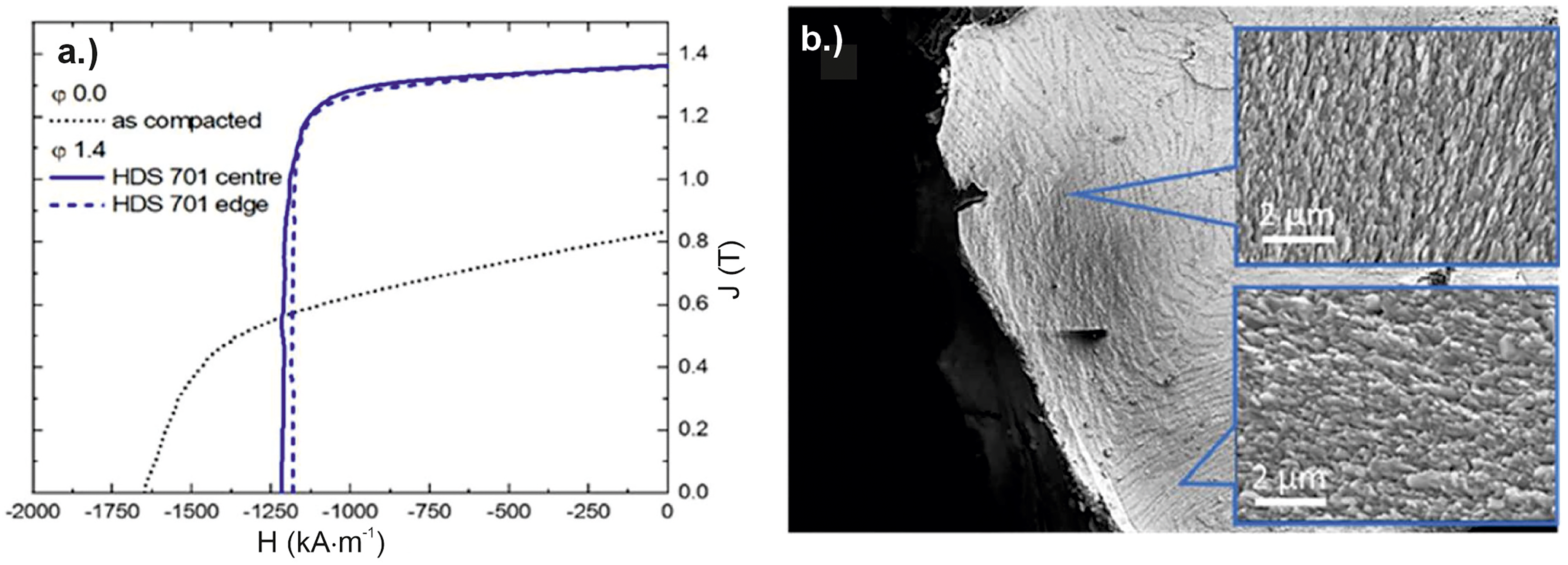
(a) Magnetisation curves of sample HDS 701 measured on specimens cut from the centre (solid line) and the edge (dashed line) of the sample. (b) Overview SEM-SE image of sample HDS 791 with well-pronounced grain misalignment at the sample edge due to the low density of the compacts.
For simplification only the curves representing the centres of the specimen are shown in Figure 13(a) and 13(b). As shown in Figure 13(a), the samples deformed under pressures of 50 and 60 MPa have the same remanence, but lower coercivity which can be explained by grain coarsening. Further increasing of the deformation pressure to 80 MPa results again in lower coercivity (Figure 13(b)). As discussed before, SEM micrographs show grain coarsening in this sample. By decreasing the deformation temperature to 725 °C, this problem was partially overcome (HDS 802 in Figure 13(b)). This result indicates that, while good texturing of the grains can be achieved by hot deformation at relatively low pressure, magnetic properties are extremely sensitive to all process parameters.
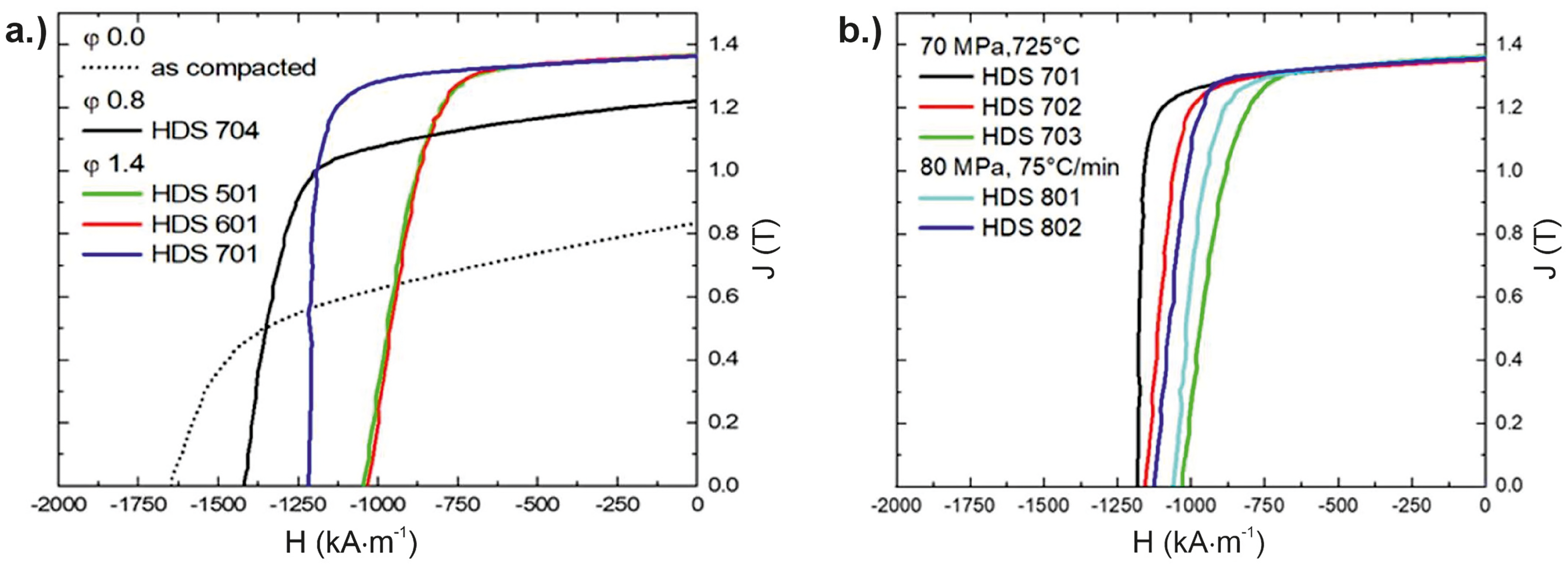
Magnetisation curves of the samples from series HDS produced under varying different parameters: (a) varying deformation pressure between 50 and 70 MPa by constant deformation temperature; (b) varying ramping speed, deformation pressure and temperature.
Benchmark of Nd–Fe–B SPT
The SPT hot deformation experiments conducted at Forschungszentrum Jülich (marked in Figure 14 with green colour) are still preliminary and exploratory in nature. Even though a high densification of around 96% was achieved for sample T700-50, the magnetic properties remained predominantly isotropic, suggesting the absence of texture. Increasing the temperature to 800 °C while keeping the pressure of 50 MPa constant slightly improved the remanence, but significant decrease of coercivity indicated the onset of anomalous grain growth. Increasing the pressure to 500 MPa further increased the remanence to 1.25 T, but longer dwell time at 800 °C for achieving this pressure were counterproductive for the coercivity. The results indicate the expected positive influence of high pressures for microstructure texturing, but the applied temperature of 800 °C was too high to reliably avoid anomalous grain growth. The increased grain growth at higher pressure is a phenomenon, which is not fully understood and therefore requires further investigations. It is possible that a combination of a lower temperature (such as 700–750 °C) combined with high pressure could be a parameter set of interest. As particle contacts tend to heat up more due to Joule heating, localised Nd-rich grain boundary liquid phase could lead to a more controlled mass transfer than with an 800 °C setpoint. Likely the samples processed at 800 °C were experiencing higher temperatures between particles than the bulk, therefore leading to larger grains.
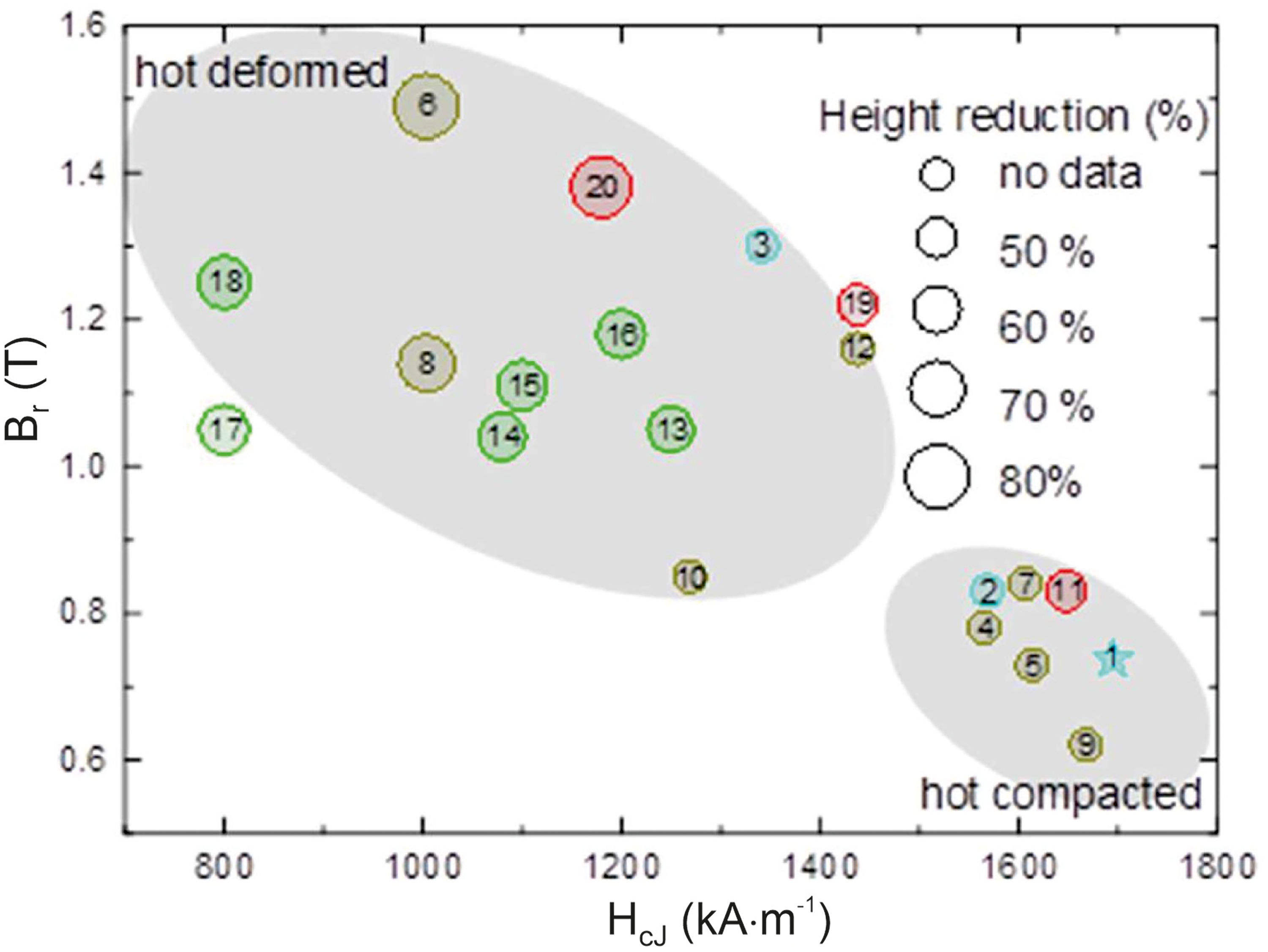
Magnetic properties of Nd–Fe–B magnets made by FAST/SPS starting from melt-spun powders. The numbers are the consecutive numbers given in Table 3. Green colour stands for the T- and P-series of Forschungszentrum Jülich; red colour stands for the HDS-series of Fraunhofer IWKS; the influence of the deformation degree on magnetic properties is pointed out. For reference, the values of the starting MQU-F powder (labelled as 1) and the commercial magnets from WILO (2 for hot compacted, 3 for hot deformed) are shown in blue colour.
Significantly better results were achieved in the SPT attempts done at Fraunhofer IWKS, where dense compacts were used for hot deformation (marked in Figure 14 in red). These SPT hot deformed samples can fully deform to the diameter of the outer die with crack-free edges only if a sufficient height reduction is achieved. Further investigations on the height reduction on the microstructure and the magnetic properties should be carried out in the future, as this work is preliminary in SPT optimisation. Despite the scale of pressure increase being an order of magnitude lower than the SPT of the semi-dense compacts, grain growth was still observed. The best observed results were from HDS701, which was SPT hot deformed at 70 MPa, 750 °C with a height reduction of 75%. The magnet had a Br = 1.38 T, HcJ = 1180 kA m−1, and (BH)max = 353 kJ m−3. This varies from the best performing SPT semi-dense samples, such as T750-50 (62% height reduction, Br = 1.11 T, HcJ = 1087 kA m−1, and (BH)max = 215 kJ m−3) and P800-100 (60% height reduction, Br = 1.18 T, HcJ = 1203 kA m−1, and (BH)max = 249 kJ m−3). Significant differences in magnetic behaviour between SPT samples deformed at similar parameters, such as HDS701 and T750-50, may be attributed to several reasons. For magnetic characterisation, in the case of HDS701, a rectangular piece was cut from the centre of the sample and measured. T750-50, however, was half of a circular sample. The effect of this cutting likely caused variation in remanence. While the remanence of T750-50 is expected to be somewhat lower than in the case of HDS701 due to a 20 MPa difference in deformation pressure, the inclusion of more of T750-50's edge in magnetic characterisation likely affected the remanence as well, as undoubtedly the edge was less dense than the centre of the sample. A similar trend was observed in the work of Sawatzki et al. 56 Degree of deformation between semi-dense and dense compacts also carries different implications, as semi-dense compacts contain more space to be overcome between the particles during the SPT deformation. Difference in starting sample mass, diameter, and deformation diameter may also have an effect on the final magnetic performance. Experiments that normalise the amount of deformation relative to the starting mass are necessary for complete direct comparison between methods.
In Figure 15, the development of the magnetic performance of the best performing samples of the HDS series at the different processing stages are presented. The magnetic properties of the initial MQU-F powder were measured using spherical specimens of isotropic powder consolidated and mixed with 5 wt. % of epoxy resin. The magnetic performance of all other samples shown was measured using rectangular specimens, cut from the sample centre. All curves were corrected with their corresponding demagnetisation factor. The step-like change in the magnetisation loop of the initial isotropic MQU-F powder indicates the presence of a certain amount of amorphous phase fraction. The magnetisation curve of the hot deformed sample indicates that, during the hot compaction prior to SPT deformation, the amorphous fraction crystallises into nanometer-sized grains while still remaining isotropic. As a result, the coercivity is slightly improved, while the saturation magnetisation remains unchanged. The latter confirms that grain growth during the compaction process was avoided. During the subsequent hot deformation process, anisotropy is induced by the deformation and alignment of the nanocrystalline grains (see Figure 9). As result of hot deformation, in the case of sample HDS 701 the coercivity is reduced by ca. 20%, while the remanence is increased by ca. 32%. These values are connected with the degree of deformation defined by sample height reduction during SPT. In Figure 15, the magnetiszation loops are displayed for samples with different height reductions produced by SPT in the present work (selected samples from the HDS-series) and compared with conventionally hot-pressed samples from the work of Sawatzki. 56 As it can be seen, the SPT samples have the same performance (Sample HDS 704: Br = 1.22 T, HcJ = 1438 kA m−1, and (BH)max = 272.5 kJ m−3 and sample HDS 701: Br = 1.38 T, HcJ = 1180 kA m−1, and (BH)max = 353 kJ m−3 for 50 and 75% height reduction) as the conventionally hot-pressed/die-upset samples, but with a significantly higher degree of deformation. This effect could be of interest from an application standpoint but requires further investigation. One possible explanation for the different deformation behaviour could be the different way how pressure is applied during both processes. In our SPT approach, the applied pressure is constantly increasing, while in hot-pressing, the pressure was applied in a way ensuring a constant displacement speed and therefore constant deformation rate.
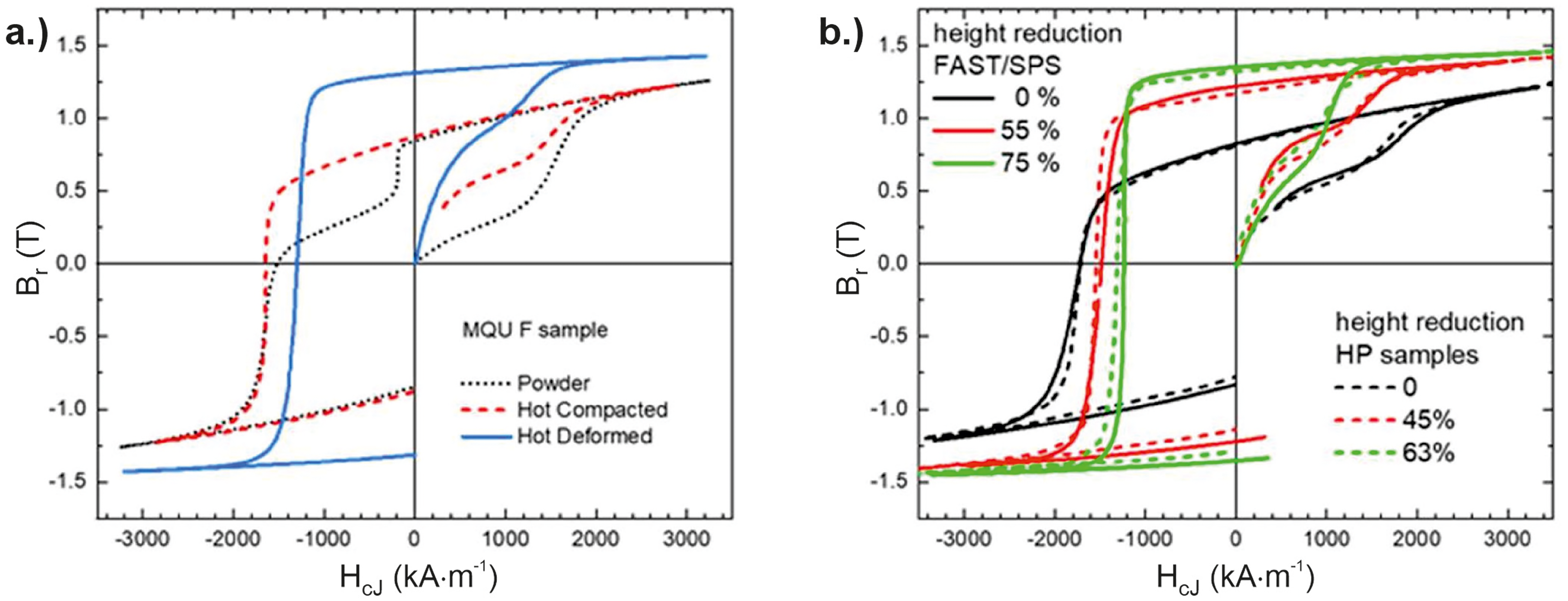
Magnetisation curves of samples made from melt-spun MQU-F powder. (a) Change of magnetisation behaviour during the different processing stages: Powder, hot-compacted by FAST/SPS, hot-deformed by FAST/SPS (HDS 701). (b) Comparison of magnetisation behaviour of Nd–Fe–B magnets made by FAST/SPS (HDS-series) and conventional HP. 56 The differences in height reduction for both techniques resulting in similar magnetic properties are pointed out.
In the literature, the best results of hot deformation by SPT were achieved by Liu et al. 43 and Wang et al.. 47 Liu et al. performed SPT hot-deformation on an MQP-UG powder at 400 MPa and 700 °C, achieving a height reduction of 80%. The magnetic performance of this sample was Br = 1.492 T, HcJ = 1004 kA m−1, and (BH)max = 400 kJ m−3. It should be noted that in this study, samples for magnetic performance were taken from the centre of the magnet and did not include the magnet edge. Optimally this magnetic performance would be homogenous throughout a full SPT magnet. However, as the edge was not tested in this study, information regarding sample homogeneity is unknown.
Wang et al. performed the hot deformation of MQP-F powder at 500 MPa and 700 °C, resulting in a height reduction of 70%. The authors reported magnetic properties of Br = 1.42 T, HcJ = 1227.9 kA m−1, and (BH)max = 383.9 kJ m−3. In the study of Wang et al., it has been demonstrated that the current pulse ratio (CPR) is an additional influence factor for tuning the magnetic properties. Magnets prepared with a CPR of 2:2 (= pulse length of 6.6 ms) outperformed the performance of magnets prepared with a CPR of 12:2 (= pulse length 39.6 ms). In the latter case, the properties were slightly lower with Br = 1.37 T, HcJ = 1205.6 kA m−1, (BH)max = 352.2 kJ m−3. The authors argued that the amount of partial liquid phase during deformation is reduced with shorter pulse length reducing the decomposition of the Nd2Fe14B phase during hot deformation. Though change in CPR was not conducted in this work, it adds another layer of possibility for fine-tuning parameters to produce optimised SPT magnets. When benchmarking the results of Liu et al. 43 and Wang et al., 47 it must be considered that powders from MQP series were used as starting materials, which are – according to the manufacturer Neo Magnequench – usually applied for bonded magnets and not optimised for hot deformation. 58
Conclusions
Our results reveal that near-dense Nd–Fe–B pre-forms, which were then hot deformed by SPT approach, have shown good magnetic performance, with some even exceeding the properties of some commercial anisotropic Nd–Fe–B magnets. The best performance was achieved with a SPT-deformed dense magnet (sample name HDS701), which was pre-sintered to almost theoretical density by FAST/SPS (75 °C min−1, 725 °C, 45 MPa, 1 min) and then SPT hot deformed at 70 MPa, 750 °C with a height reduction of 75%. The magnet had a Br = 1.38 T, HcJ = 1180 kA m−1, and (BH)max = 353 kJ m−3. A specific challenge of FAST/SPS devices is the need to apply a pre-load to ensure sufficient electrical contact. Therefore, samples had to be pre-sintered when conducting hot-deformation in a FAST/SPS device. Our study reveals that dense compacts are – similar to conventional magnet production by hot pressing and die-upsetting – preferred for achieving homogeneous deformation, reliably avoiding cracks at the edges and improved texture. Another challenge is the avoidance of anomalous grain growth during pre-sintering as well as during hot deformation. The risk of anomalous grain growth is significantly enhanced if the FAST/SPS temperature exceeds 700 °C in either hot compaction or SPT hot deformation. Contrarily, temperatures beyond 700 °C are advantageous for full densification in the shortest possible time. Therefore, fine tuning of temperature and dwell time is an absolute must. Our studies show the influence applied pressure has on promoting anisotropic grain growth. The observation that higher pressures even accelerate grain growth requires further investigation.
SPT of semi-dense Nd–Fe–B pre-forms, however, did not manage to challenge the performance of commercial hot-deformed Nd–Fe–B magnets. Though the highest magnetic performance was not observed when doing hot deformation by SPT starting from a semi-dense compact, room for parameter adjustment and optimisation exists. The benefit of minimising grain growth with a 500-°C pre-sinter phase is the potential processing of anisotropic magnet scrap in the matrix. Future investigations will continue with both optimising the low-temperature, semi-dense route with gradual introduction of crushed recycled magnetic scrap. Potentially SPT hot deformation of these semi-dense mixed-recycled compacts at high enough temperature could also induce grain rotation in the anisotropic scrap to align grain c-axis with the uniaxial pressing force. Nevertheless, further work is needed before this can be achieved.
Footnotes
Acknowledgements
This work was supported by the German Research Foundation (DFG) under the grant numbers BR3418/1-2 and GU514/8-2. Furthermore, parts of the work were done in the framework of the project ‘EnerGieeffiziENtE KreiSlaufwirtschaft krItischer RohStoffe GENESIS’ funded by the German Ministry of Economic Affairs and Climate Action (BMWK), Förderkennzeichen 03EI5009D according to a decision of the German Federal Parliament. The work performed at Fraunhofer IWKS and TU Darmstadt was supported by BMWK in the frame of the RecycleTeam project. Furthermore, the work of I.R. was also supported by the Fraunhofer Internal Programs under Grant No. Attract 170-600006. T.M. is supported from Ondokuz Mayıs Üniversity, Scientific Research Project Department under the grant (PYO.MUH.1922.2022.001). All funding and the experimental support of Ralf Steinert are highly acknowledged. Furthermore, comprehensive fundamental work of Dr Tarini Mishra on Flash SPS of Nd–Fe–B magnets partly contributing to the parameter selection for spark plasma texturing in the present work is highly acknowledged.
Authors contributions
M. Keszler performed experimental work at Forschungszentrum Jülich, writing and revision of manuscript; I. Radulov did funding acquisition, experimental work at Fraunhofer IWKS, writing and revising; F. Maccari performed characterisation and interpretation of the magnetic results; T. Mutuk did hot deformation by FAST/SPS at high pressure; M. Krengel did magnetic measurements on selected samples; O. Guillon performed supervision of the work at Forschungszentrum Jülich, discussion of results; O. Gutfleisch did funding acquisition, supervison of the work at Fraunhofer IWKS and TU Darmstadt, discussion of results, revising; M. Bram did funding acquisition, supervision, writing first draft of manuscript.
Declaration of conflicting interests
The authors declared no potential conflicts of interest with respect to the research, authorship and/or publication of this article.
Funding
The authors disclosed receipt of the following financial support for the research, authorship and/or publication of this article: This work was supported by the Bundesministerium für Wirtschaft und Klimaschutz, Ondukuz Mayis University, Fraunhofer-Gesellschaft, Deutsche Forschungsgemeinschaft (grant number 03EI5009D, RecycleTeam Project, PYO.MUH.1922.2022.001, 170-600006, BR3418/1-2, GU514/8-2).