
Abstract
A gas atomised Ti-6Al-4V powder, classified as out-of-specification for additive manufacturing (AM), was consolidated via Field-Assisted Sintering Technology (FAST). Fully dense 250 mm diameter discs with lamellar or bimodal microstructures were produced by FAST processing either above or below the β-transus temperature. Static and dynamic mechanical properties were assessed by testing full-size specimens in the ‘as-FAST’ condition. Material from both processing conditions exceeded the ASTM Ti-6Al-4V powder metallurgy requirements for yield/tensile strength and elongation. Furthermore, material from the edge of the disc processed below the β-transus temperature meets ASTM requirements for wrought Ti-6Al-4V. Fatigue performance also compared favourably with conventionally processed Ti-6Al-4V. This work establishes that surplus AM powders can be successfully recycled via the one-step FAST process and provides confidence that this ASTM-grade material can be used in a range of applications under both static and dynamic loading, which will improve the sustainability credentials of the AM sector.
Keywords
Introduction
Powder-based additive manufacturing (AM) of titanium alloys is becoming established in a range of sectors, such as biomedical and aerospace. As confidence in AM processes develops, the supporting supply chains need to ensure that the product is cost-effective; powder producers are facing increased scrutiny as feedstock adds significantly to the overall cost associated with producing AM parts (∼30% 1 ). A contributing factor is that each AM technique operates most effectively with a specific and narrow powder size distribution optimised for that process, for example, electron beam powder bed fusion requires ∼45–106 µm powder and laser powder bed fusion requires ∼15–45 µm powder, whilst directed energy deposition (DED) uses ∼45–150 µm powder.2,3 This is exacerbated as manufacturing powder by plasma/gas atomisation (PA/GA), or the plasma rotating electrode process (PREP), produces a range of particle sizes distributed around a target average diameter. This means a significant portion (>30–50%, 4 pp. 58–59) of the powder produced is in size fractions unusable in AM, that is, undersized, oversized, or too irregular in morphology. As a result, powder producers are stockpiling unusable titanium alloy powder, which questions the future sustainability credentials of AM. It is complex and costly to remelt this surplus powder into usable size fractions, as significant oxygen/nitrogen pickup can adversely affect final mechanical properties. Fortunately, such powder can be consolidated using hot isostatic pressing (HIP), conventional sintering, or more recently via field-assisted sintering technology (FAST; also known as spark plasma sintering [SPS]) 5 ; either into near-net shapes 6 or into forging feedstock (FAST-forge 7 ). FAST has an advantage over other consolidation techniques as the total processing cycle time is usually reduced and lower temperatures can often be utilised.8–10 Recently, it has been demonstrated that good temperature control can be maintained with consistent microstructures generated in a range of commercial titanium alloys. 5 Not only are homogeneous microstructures generated from powder and even machining swarf11,12 but the resulting material behaves isotropically due to a weak compressive texture. 13
Titanium alloys are allotropic, with a transition temperature where the low-temperature hexagonal close-packed β phase transforms to the high-temperature body-centred cubic β phase. FAST processing schedules are designed with respect to this β-transus temperature, very much like traditional forging and hot rolling practices. The most widely used titanium alloy in industrial applications is Ti-6Al-4V, which means it is also the most used feedstock powder for AM of titanium alloys. Ti-6Al-4V is an α+β type alloy that has β-transus temperature of approximately 990°C; FAST processing above 1000°C leads to the evolution of large transformed β grain structures, whereas processing at 900–950°C will lead to fine-scale equiaxed structures with primary α grains in a transformed β matrix. This ‘bimodal’ or ‘duplex’ microstructure typically gives the best balance of mechanical properties, but the transformed β grain structure can be useful for applications when improved resistance to creep, oxidation, stress corrosion, and crack propagation is required. 14
Despite FAST furnaces becoming more common in research institutes and industry, the reporting of mechanical properties from FAST-processed materials is often limited due to the typically small samples produced. 10 Mechanical properties of FAST-processed titanium alloys have been obtained by compression testing15–17 and inferred from hardness testing.15,16,18 Tensile strengths from sub-size test specimens have also been reported; for example, ∼350 MPa with ∼30% elongation for < 45 µm GA grade 1 CP-Ti and ∼600 MPa with ∼15% elongation for < 45 µm angular grade 3 CP-Ti, 19 978–1045 MPa with 6.3–18.2% elongation for < 45 µm GA Ti-6Al-4V, 20 1240 MPa with 19.5% elongation for 75–150 µm GA Ti-6Al-4V through manipulation of FAST load and temperature to create a ‘bimorphic’ microstructure, 21 844/893 MPa with 12/17% elongation for 53–106 µm GA Ti-6Al-4V either as-FAST or with subsequent heat treatment, 22 and 1183 MPa with 6% elongation for Ti–5Al–5V–5Mo–3Cr created from blended elemental 10–80 µm angular and spherical powders. 23 Several studies have also examined the potential to enhance mechanical properties of titanium alloys by performing extensive milling of the powders prior to FAST consolidation24–28; although it was reported that the fatigue life of both un-milled and milled powders was 74% of the materials’ tensile strength.
In this paper, both static and dynamic mechanical properties of 75–500 µm gas atomised (GA) Ti-6Al-4V powder recycled through FAST are investigated. This feedstock was deemed out-of-specification for additive manufacturing by the powder manufacturer. Full-size test specimens were tested in the ‘as-FAST’ condition with no additional processing or heat treatment undertaken, nor any pre-treatment of the feedstock powder. The results of these tensile and four-point-bend fatigue tests will provide both the AM supply chain and future users of FAST technology confidence in the properties developed from this sustainable and rapid process.
Materials and methods
Materials
The material used in this study was a Ti-6Al-4V gas atomised (GA) powder manufactured by Puris LCC, Bruceton Mills, WV, USA, and certified to contain 6.11% Al, 4.07% V, 0.17% Fe, 0.025% C, 0.0005% H, 0.005% N, and 0.135% O: therefore, meeting the ASTM Grade 5 Titanium specification. 29 The powder provided was sieved by the manufacturer to a size range of 75–500 µm. The particle size distribution was subsequently measured using a Malvern Mastersizer 3000 laser diffraction particle size analyser with the wet dispersion method. A total of 20 repeat measurements were made and the average result can be seen in Figure 1(a), with analysis showing that the Dx(10) was 105 µm, Dx(50) was 203 µm, and Dx(90) was 408 µm (where, respectively, 10%, 50%, and 90% of the particles have diameters less than the stated value). This particle size distribution illustrates that 65% of the powder particles are larger than are typically usable within AM processes.
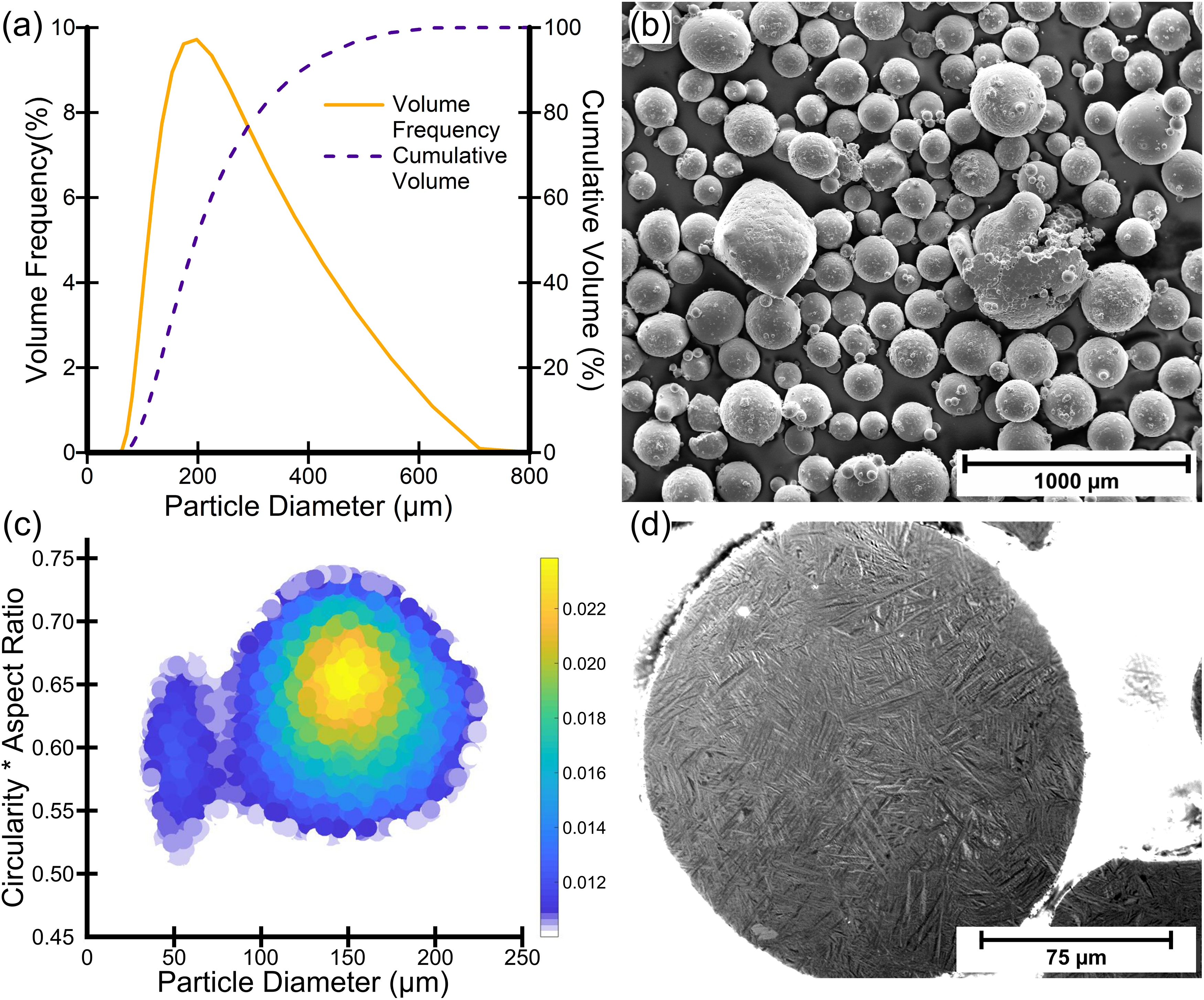
Overview of the out-of-specification additive manufacturing Ti-6Al-4V GA powder (a) Graph of particle size distribution. (b) Secondary electron SEM micrograph showing particle morphology. (c) Graph of the probability density of the relationship between powder particle diameter, aspect ratio, and circularity. (d) Cross-polarised light micrograph showing the powder microstructure.
The powder morphology was nominally spherical, although there are a significant number of particles that are partially melted, fused together (including ‘satellites’), misshapen, or have visible voids/pores, see SEM images in Figure 1(b). The microstructure observed in the powder particles, shown in Figure 1(d), is martensitic, consisting of very fine needle-like α laths that formed when cooling rapidly from the molten state during the GA process.
The aspect ratio, circularity, and porosity of the powder were also characterised, using an Olympus Bx51 light microscope equipped with a Clemex Vision PE image analysis system and software. The powder was cold mounted in epoxy resin, followed by standard titanium alloy metallographic preparation, then 8000 particles were automatically analysed by the Clemex software. Figure 1(c) shows the probability density of the relationship between the powder particles’ diameter and aspect ratio multiplied by circularity (i.e., the likelihood that particles within a certain diameter interval will have a specific value of circularity multiplied by aspect ratio; larger values indicate higher probability, and a zero value indicates zero probability). The Y axis represents the product of the aspect ratio and circularity as this indicates how close a particle is to a perfect sphere, which would have a value of one for both circularity and aspect ratio. It is observed none of the particles are perfectly spherical. Values of the product of circularity and aspect ratio fall between 0.5 and 0.75 across all sizes, representing significantly misshapen and/or agglomerated particles, which correlates well with the SEM images in Figure 1(b). The Clemex software also measured that 8.2% of the observed powder particles contained pores, with the area of these pores equating to a porosity value of 0.74% compared to the total area of the 8000 measured particles.
Field-assisted sintering technology
The FAST system used was an FCT Systeme GmbH Type H-HP D 250/C and is shown in Figure 2(b). Two 250 mm diameter, 32 mm thick, Ti-6Al-4V discs were manufactured by placing 7000 g of the GA Ti-6Al-4V powder into the centre of a graphite die assembly. The die assembly, see Figure 2(a), consists of a graphite ring die that contains an upper and lower graphite punch, an upper and lower carbon–fibre–carbon (CFC) composite heater plate (to aid with temperature homogeneity), and an upper and lower graphite wear plate (to prevent damage to the CFC plates). The titanium alloy powder was isolated from contact with the graphite die items by use of graphite foil to aid with specimen removal and prolong die life. The ring die was lined with one layer of 0.35 mm thickness foil and six 250 mm diameter, 0.35 mm thick, foil discs were placed between the powder and the upper/lower graphite wear pad; three above and three below. The use of graphite foil to line the ring die also ensures a friction fit with the graphite punches, CFC heater plates, and wear pads to prevent excessive leakage of material during processing. Upper and lower graphite spacers were used to reduce from the diameter of the conducting hydraulic rams to the graphite punches. A CFC collar was placed around the graphite ring die to increase its strength. Two layers of graphite felt insulation were placed around the CFC support collar to improve efficiency of the system by reducing heat loss.
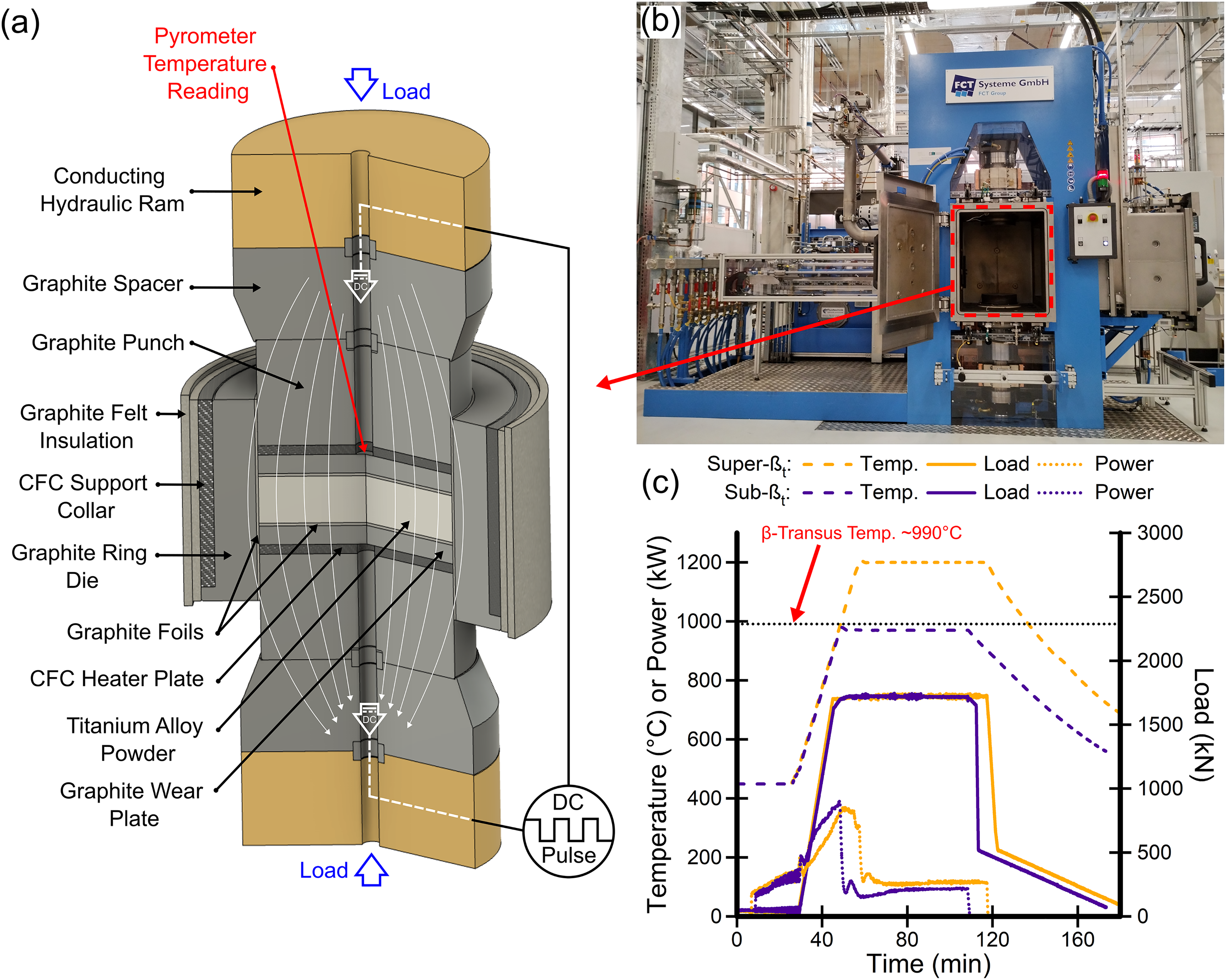
(a) Schematic diagram indicating the main components of the FAST furnace and graphite die assembly. (b) Photograph of the University of Sheffield's FCT Systeme GmbH Type H-HP D 250/C FAST furnace used in this study. (c) Graph of the pyrometer temperature, applied hydraulic ram load, and power consumption during the 970°C FAST cycle (‘sub-βt’) and the 1200°C FAST cycle (‘super-βt’).
This die assembly was then loaded between two conducting hydraulic rams in the machine's vacuum chamber and held with a put-on load of 50 kN to ensure good electrical contact was made. The following sintering cycle was then used, see Figure 2(c). The vacuum chamber was evacuated to 0.5 mbar and then a pulsed (15 ms on, 5 ms off) DC current applied. The heating rate was uncontrolled up to 500°C due to the operating limits of the control pyrometer. Above 500°C, a constant heating rate of 25°C.min−1 was used up to the dwell temperature (970 or 1200°C), and the applied load was increased at a rate to reach maximum value (1720 kN/35 MPa) by 900°C. The sample was held for a dwell time of 60 min at these maximum conditions, and then the current was turned off and the die assembly allowed to cool. Initially the load was decreased to 500 kN over 5 min to relieve mechanical stress on the graphite die. The load was then gradually decreased back to 50 kN over the following 60 min to ensure sufficient contact was maintained to assist with conductive cooling through the hydraulic rams; reducing the load too quickly slows the cooling rate and increases processing cycle time. The required heating power rose from 160 to 360 kW during the temperature ramp from 500°C to 970/1200°C and settled at 78/114 kW, respectively, during the dwell period.
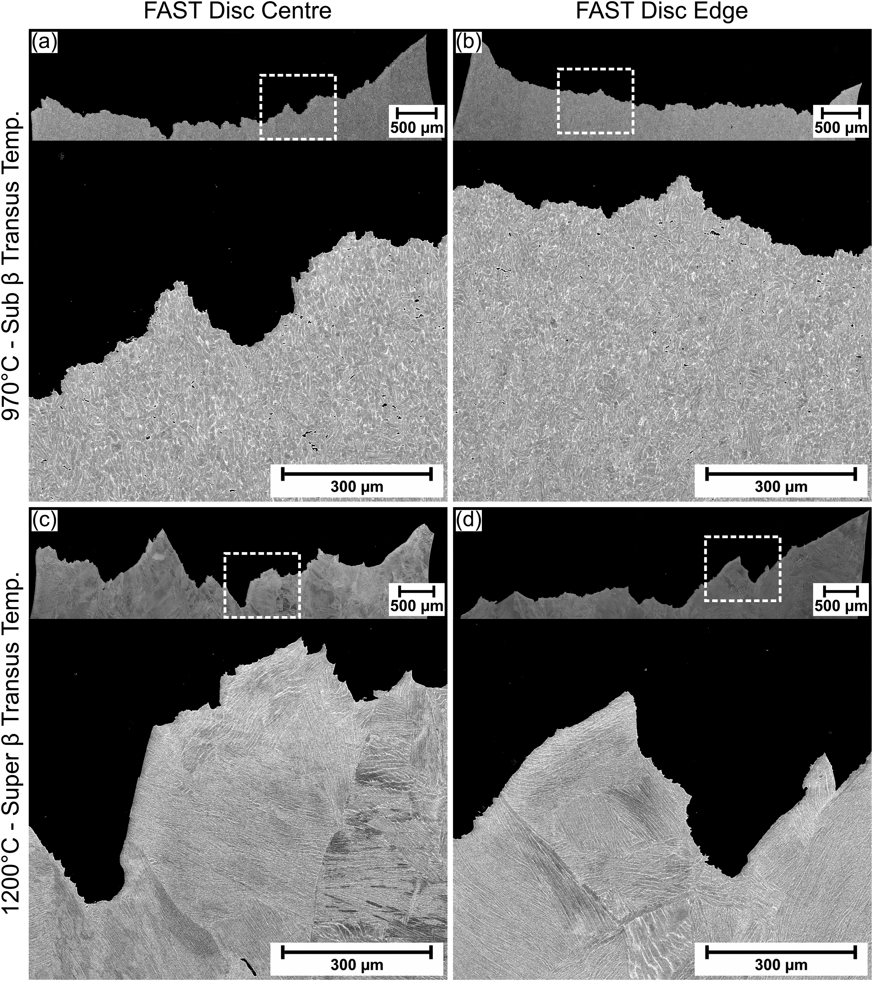
Throughout the remainder of the paper, the FAST disc produced at 970°C will be referred to as sub β-transus temperature material (‘sub-βt’) and the FAST disc produced at 1200°C will be referred to as super β-transus temperature material (‘super-βt’). The microstructure produced by these two different FAST processing temperatures are shown in Figure 3, where the β phase appears lighter due to preferential segregation of the heavier alloying elements. The sub-βt sample microstructure is the bimodal/duplex structure typically obtained when hot-working Ti-6Al-4V high in the α+β phase region (∼50°C below the β-transus temperature), 30 see Figure 3(a) and (b). There are approximately equiaxed ∼10–20 µm primary α grains contained in a matrix of transformed β grains consisting of coarse α laths separated by retained β phase. The super-βt sample microstructure is the expected transformed β phase microstructure that is characteristically found after slow cooling from above the β-transus temperature, 30 see Figure 3(c) and (d). These prior β grains are ∼300–900 µm in diameter and contain ∼50–300 µm colonies of ∼1–10 µm α laths separated by retained β phase with further α phase present on some prior β grain boundaries. In both the sub-βt and super-βt samples the microstructure is homogeneous, with no observable differences from centre-to-edge of the FAST discs as can be seen when comparing Figure 3(a) with (b), and Figure 3(c) with (d). There is also no visible porosity, indicating that high levels of consolidation and diffusion bonding of particles has occurred during FAST processing. The microstructure of the starting powder particles has been completely transformed and no visible traces of the original prior powder particle boundaries remain. It can be seen in Figure 4(a) that a small lip has formed on part of the sub-βt FAST disc. The combination of heat and applied load enables the Ti-6Al-4V to deform the graphite foil lining the ring die, creating a gap for the softened material to be squeezed into. This effect is exacerbated by increased temperature, load, and dwell time.
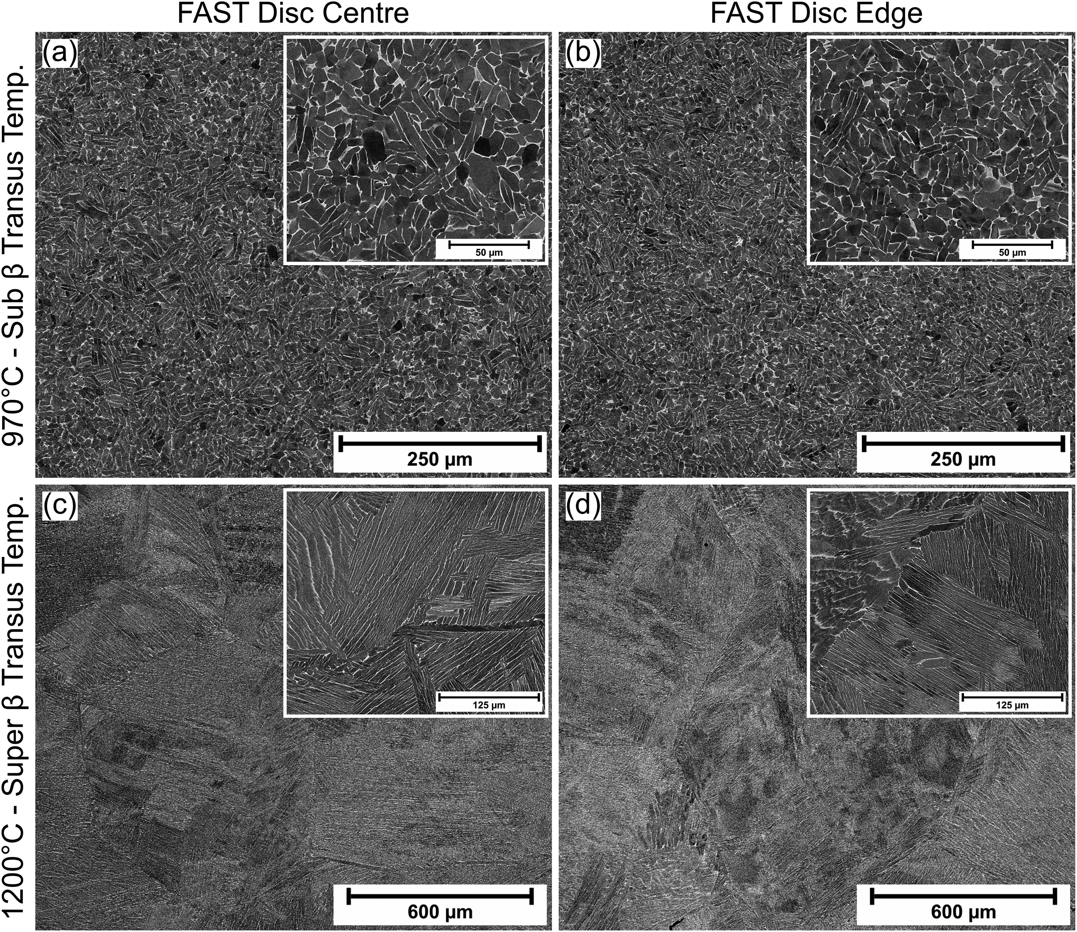
Backscattered electron SEM micrographs showing the microstructure of the Ti-6Al-4V GA powder after FAST processing at 970°C (a + b) and 1200°C (c + d), at the central region of the FAST disc (a + c) and the edge region of the FAST disc (b + d).
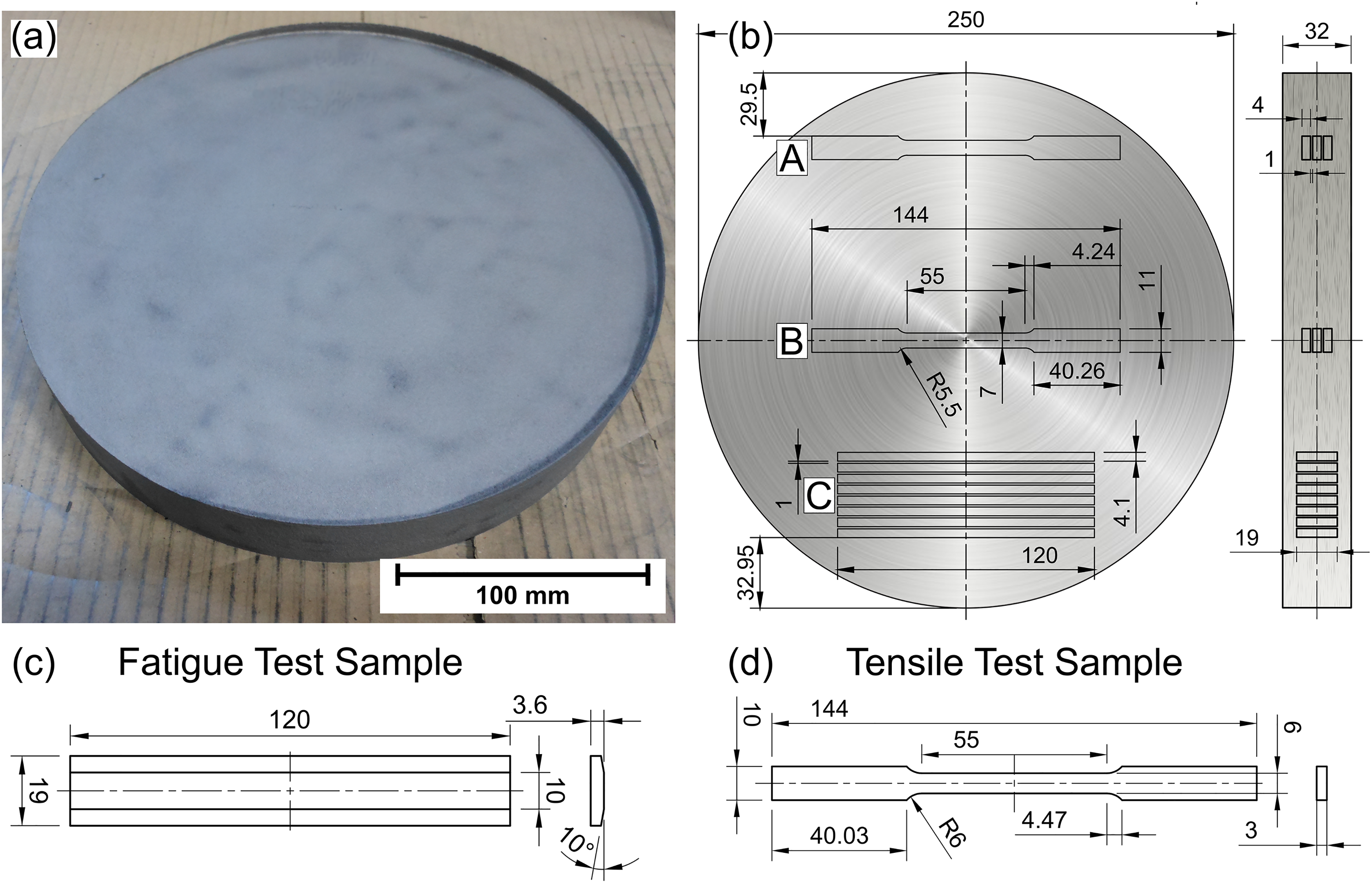
(a) Photograph of the 250 mm diameter sub-βt FAST disc. (b) Schematic showing the locations for the wire-EDM extraction of the oversized test specimen blanks; tensile edge at ‘A’, tensile centre at ‘B’, and fatigue at ‘C’. (c) Final dimensions of the fatigue test specimens. (d) Final dimensions of the tensile test specimens.
Tensile testing
Tensile samples were produced from the 250 mm diameter sub-βt and super-βt FAST discs (see Figure 4(a)) through extraction of an oversized blank by wire electric discharge machining (wire-EDM). For each disc, a total of six samples were extracted, three of from the edge and three from the centre, see labels A and B, respectively, in Figure 4(b) for sample locations. The oversized blanks were then finish machined to ASTM E8/E8 M specifications, 31 see Figure 4(d) for dimensions.
The tensile test was carried using a Tinius Olsen 25 ST benchtop test machine and LabView software was used to measure the force and displacement. The LabView software recorded the force data directly from the tensile tester while the displacement was recorded from an Epsilon Axial Extensometer – Model 3542 with a gauge length of 50 mm. The crosshead of the tensile tester was set to a constant displacement of 0.01 mm.s−1.
Fatigue testing
Fatigue testing was carried out employing a custom-designed, non-standard four-point bend flexural loading configuration. Under these loading conditions, specimens are subject to a large area of tensile stress applied to a machined test surface. Similar loading conditions are typical for many titanium alloy structural components used in fatigue-critical applications. Further details regarding the fatigue test method can be found in previous studies by the authors.32–35
Specimen fabrication was carried out by removal of oversized blanks from the FAST billets by wire-EDM. For each disc, a total of eight samples were extracted, see label C in Figure 4(b) for sample locations. The blanks were then face milled to final dimensions of 3.6 × 19 × 120 mm by machining of the specimen surface subjected to maximum tensile bending stresses (the 19 × 120 mm surface). This process was performed using parameters representative of a typical standard finishing operation with respective settings for cutter feed (fz), speed (Vc), and axial depth of cut (ap) of 0.08 mm.tooth−1, 60 m.min−1, and 0.5 mm. Tooling was provided by Seco Tools and consisted of a 25 mm diameter indexable square shoulder milling cutter (R217.69–2525.3–10–4A) and coated WC-Co inserts (XOMX10T304TR-ME07). Following machining of this surface, adjacent chamfer surfaces were machined at a chamfer angle of 10° using the same tooling setup and parameters to give a 10 mm upper face width, see Figure 4(c) for dimensions.
Fatigue testing was conducted at ambient conditions under sinusoidal loading applied through 10 mm diameter rollers (BS 8734/ISO 8734), positioned at a span distance, L of 80 mm. The ratio between the inner and outer roller spacing distance was L/2. Tests were carried out with a stress ratio (R) of 0.1 and subjecting each specimen to maximum stress (SMax) conditions sufficient to induce local plasticity; either 950 MPa for the sub-βt material (SMax = 1.14σy) or 850 MPa for the super-βt material (SMax = 1.10σy). A loading cycle frequency of 5 Hz was maintained throughout the test program.
In addition to the FAST processed material, a benchmark comparison was carried out with coupons taken from unidirectional (UD) rolled Ti-6Al-4V plate supplied by Rolls-Royce. Specimens were removed in orientations both parallel to (UDII) and perpendicular to (UDT) the rolling direction and machined using the same conditions as the FAST material.
Characterisation techniques
Typical metallographic preparation for Ti-6Al-4V was used for all specimens. This process involved hot mounting of sectioned specimens in Bakelite resin, followed by progressive grinding with SiC papers, and finally, chemical/mechanical polishing with a solution of 90% colloidal silica (0.05 μm) and 10% H2O2 (30% w/v). Microstructural observations were performed using either a Nikon Eclipse LV150 light microscope under reflected polarised light or an FEI Inspect F50 scanning electron microscope using secondary electron (SE) and backscattered electron (BSE) imaging techniques.
Fracture surfaces were analysed using a combination of optical and electron microscopy techniques. Macrograph images of the fracture surfaces were taken using an Alicona InfiniteFocus SL confocal microscope. Higher magnification images were taken using an FEI Inspect F50 scanning electron microscope using secondary electron (SE) and backscattered electron (BSE) imaging techniques.
Results and discussion
A summary of the static tensile properties and fatigue properties of the FAST Ti-6Al-4V material is provided in Table 1 and will be discussed in further detail in the following sections.
Mechanical properties of out-of-specification Ti-6Al-4V additive manufacturing powder recycled by processing with field-assisted sintering technology (FAST) at either below (sub-βt) or above (super-βt) the β-transus temperature.
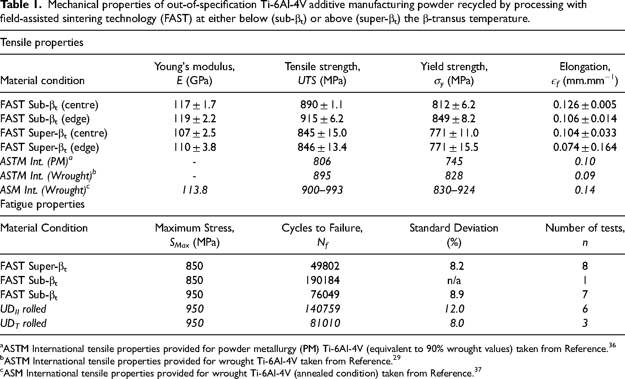
ASTM International tensile properties provided for powder metallurgy (PM) Ti-6Al-4V (equivalent to 90% wrought values) taken from Reference. 36
ASTM International tensile properties provided for wrought Ti-6Al-4V taken from Reference. 29
ASM International tensile properties provided for wrought Ti-6Al-4V (annealed condition) taken from Reference. 37
Tensile properties
The tensile stress-strain performance of the FAST Ti-6Al-4V material is presented in Figure 5 and tensile performance metrics for Young's modulus (E), ultimate tensile strength (UTS), yield strength (σy), and strain at failure (εf) are provided for the material for each processing condition and specimen location within the manufactured disc are provided in Table 1. It should be noted that the second sample taken from the centre of the super-βt FAST disc was damaged during loading into the test frame and therefore could not be tested.
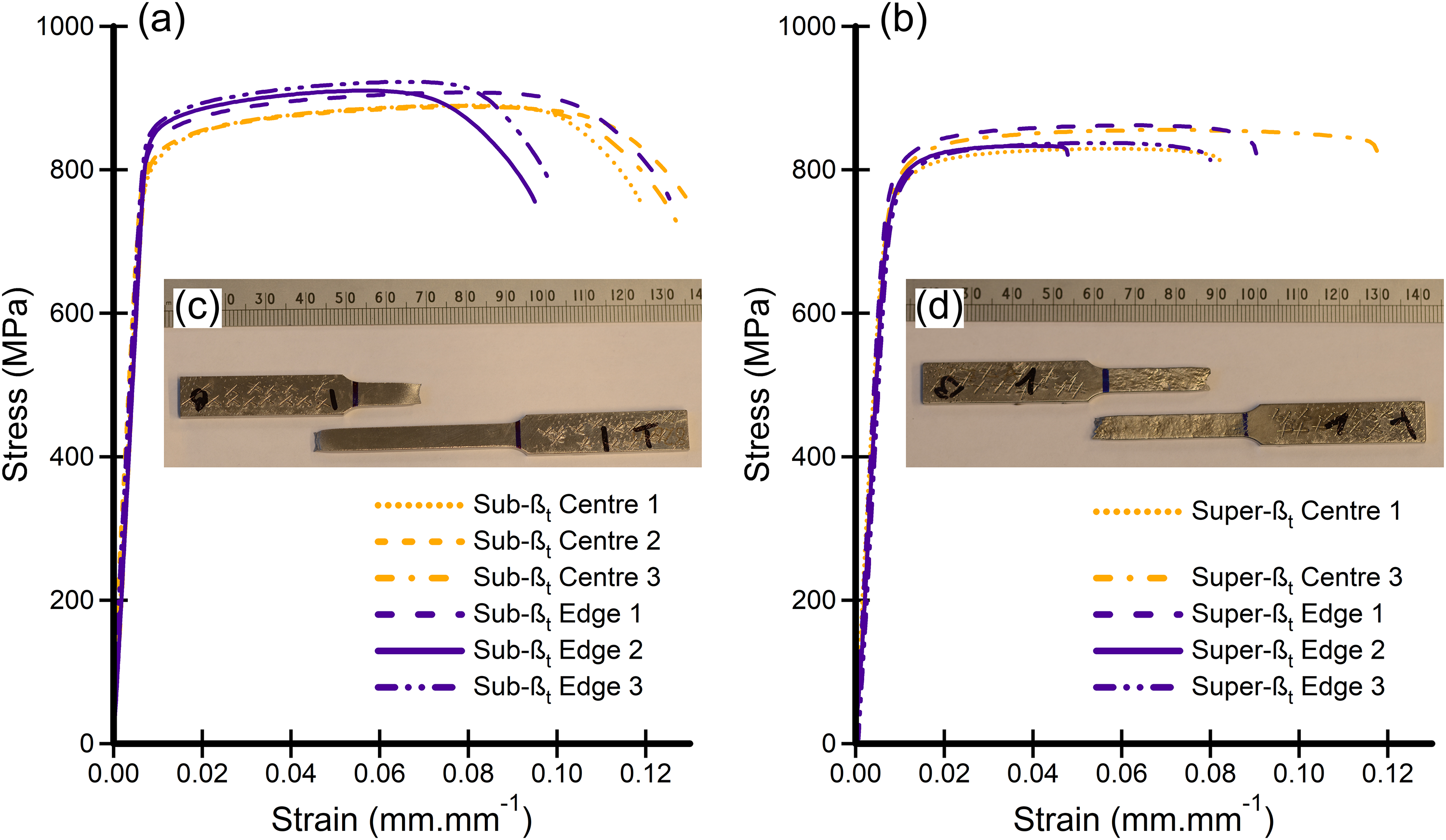
Tensile stress-strain curves and photographs of post-test FAST Ti-6Al-4V specimens corresponding to (a + c) sub-βt and (b + d) super-βt processing conditions.
The tensile performance of the sub-βt processed material can be seen to be superior compared to material processed at super-βt conditions, with material processed below the β-transus temperature displaying higher values for the UTS, σy, and εf properties. These differences in tensile behaviour can attributed to the fine equiaxed microstructure of the sub-βt processed material which provides superior tensile properties due to grain boundary strengthening effects when compared to the coarser lamella microstructure of the super-βt material due to the Hall-Petch relationship. 38
Comparisons to values from ASTM and ASM Standards for Ti-6Al-4V processed by powder metallurgy (PM) and conventional wrought methods have been provided for comparison.29,36,37 The Young's modulus displayed by the FAST processed material is comparable to the ASM International property of wrought Ti-6Al-4V and displays insignificant variation depending on either processing temperature or specimen location within the billet. The UTS, σy, and εf values for both the sub-βt and super-βt FAST material exceed those required to meet ASTM B988–18: Specification for powder metallurgy (PM) titanium alloy structural components. The UTS, σy, and εf values for the samples from the edge of sub-βt FAST disc also meet the requirements of ASTM B381–13: Standard Specification for titanium and titanium alloy forgings, although the values of UTS, σy, and εf values for the samples from the centre of the sub-βt FAST disc fall just below this standard.
The tensile stress–strain curves provided in Figure 5 show the narrow variation in performance across the specimens tested at each processing condition. Material processed at sub-βt conditions (Figure 5(a)) displays less scatter for UTS, σy, and εf than the super-βt material (Figure 5(b)). This can be attributed to anisotropic effects associated with the coarse α-colony lamella microstructure of the super-βt processed material which possesses regions of similar micro-texture within coarse prior-β grains. Unlike the sub-βt material, where tensile stresses are distributed over a volume which contains a significant number of differently orientated primary α grains, which results in isotropic and homogenous behaviour, the tensile behaviour of super-βt material is more dependent on specific α-colony orientations contained within the volume of material subjected to tensile stresses. This can vary between different specimens resulting in the observed variability in performance and is also noticeable in the post-test surface condition of the samples, see Figure 5(c) and (d).
Comparing the tensile performance of specimens taken from the centre and edge locations of the billet indicates no significant variation in the average performance for the FAST super-βt material based on specimen location. However, there is a 3% decrease in UTS and a 4% decrease in σy, for the sub-βt material from the centre of the disc compared to the edge, although there is also a 16% increase in εf. It has previously been shown by finite element modelling that temperature gradients for conducting metallic samples in a 150 mm internal diameter FAST mould (with a similar arrangement of graphite felt insulation and CFC plates as used in this research) are in the order of 40–50°C, with the edge of the sample being cooler than the centre. 39 This level of temperature gradient would produce negligible changes in Ti-6Al-4V microstructure at 1200°C where a complete transformation to the β phase has occurred above 990°C. However, assuming the centre of the sub-βt disc to be at the measured 970°C, then the edge could be at 920–930°C with a subsequent slight increase in volume fraction of primary α grains. This reduces the accompanying β grain size and therefore α colony size, which enhances tensile strength, 14 but does not explain the reduction in εf at the edge of the sub-βt disc, which requires further investigation.
The fracture surfaces of the specimens following tensile failure are shown in Figure 6. The sub-βt processed specimens display similar macroscale fracture features for specimens taken from the centre and edge billet locations (Figure 6(a) and (c)) showing typical cup and cone fracture morphology. The higher resolution micrographs (Figure 6(b) and (d)) reveal an equiaxed dimple pattern in the centre region of the fracture surface of the sub-βt specimens indicating normal mode fracture. The macroscale fracture features of the super-βt specimens (Figure 6(e) and (g)) also display similar morphologies at the centre and edge locations. At higher magnifications is possible to observe tear ridges on both specimens (Figure 6(f) and (h)). The formation of dimples is also observed in both samples. However, the test specimen from the edge locations appears to display elliptical dimples in the direction of the crack, which would indicate shear mode fracture.
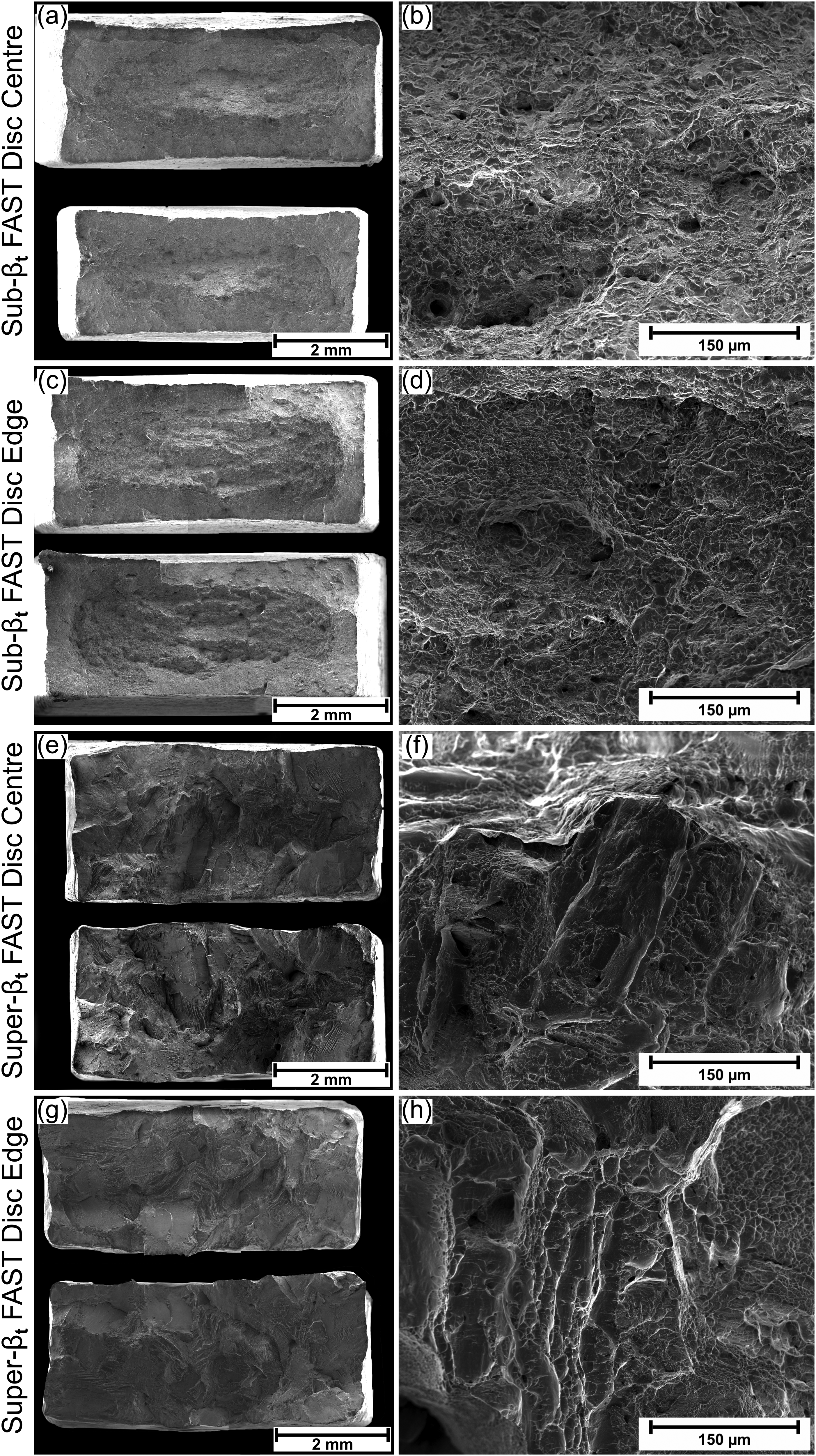
Secondary electron SEM micrographs of the fracture surfaces of the FAST Ti-6Al-4V FAST specimens following tensile failure. Low magnification images showing macro features for the sub-βt material at the centre (a) and edge (c) FAST disc locations, and super-βt material at the centre (e) and edge (g) FAST disc locations. Higher magnification images showing regions of interest for the sub-βt material at the centre (b) and edge (d) FAST disc locations, and super-βt material at the centre (f) and edge (h) FAST disc locations.
Crack paths in the plane parallel to the direction of the applied load following tensile failure are shown in the low magnification micrographs in Figure 7. Unique failure mechanisms can be distinguished for the FAST sub-βt and super-βt specimens. For the sub-βt condition (Figure 7(a) and (b)), the crack profile is considerably straighter and less tortuous than that displayed by super-βt material (Figure 7(c) and (d)). The higher magnification micrographs in Figure 7(a) and (b) show no evidence of different failure mechanisms between specimens extracted from the centre and edge locations of the sub-βt material. In both cases, the crack occurs in the β phase between the equiaxed α grains. This is more noticeable when observing the bulk material where a significant number of cracks can be seen to have generated in the β phase. Microvoids (black dots in the micrographs) are also visible in the material near to the fracture path, which are an expected part of the tensile fracture mechanism in ductile metals. The higher magnification micrographs in Figure 7(c) and (d) also do not display significant differences between specimens extracted from the centre and edge locations of the super-βt processed material. In both instances, the crack propagation mechanism is transgranular across prior β grains, with changes in crack direction broadly corresponding to transition from one colony of α laths into another of different orientation.
Backscattered electron SEM micrographs of the crack path in the FAST Ti-6Al-4V FAST specimens (in the plane parallel to the direction of the applied load) following tensile failure. Low magnification images showing macrofeatures and higher magnification images showing regions of interest for the sub-βt material at the centre (a) and edge (b) FAST disc locations, and super-βt material at the centre (c) and edge (d) FAST disc locations.
Fatigue performance
The fatigue performance data for the FAST material is provided in Table 1. The cycles to failure indicate superior performance of the sub-βt processing material in comparison to the super-βt condition with tests carried out at SMax = 850 MPa resulting in 50k cycles for the super-βt condition and an approximate four-fold performance improvement for the sub-βt condition, which failed at 190k cycles on average. Comparing the performance of the FAST sub-βt specimens with the UD rolled material indicates similar performance at SMax = 950 MPa for the two conditions when the unidirectionally rolled specimens were taken in the orientation perpendicular to rolling (UDT). Fatigue lives for these conditions were 76k and 81k cycles, respectively, for the FAST sub-βt and UDT rolled material. The highest fatigue performance was displayed by the unidirectionally rolled specimens taken in the orientation parallel to the rolling direction (UDII), which performed with an average fatigue life of 141k cycles at SMax = 950 MPa, approximately a two-fold improvement on the FAST sub-βt material. Scatter in the observed fatigue lives was shown to be consistent across all tests performed, with a typical standard deviation in the range of 8–12% of total fatigue life evident across the various material conditions. This level of variance suggests that the observations made comparing the performance of the various material conditions are of statistical significance.
Images showing the macroscale fracture surface topography of the FAST sub-βt and super-βt fatigue fracture surfaces are presented in Figure 8(a) and (b), respectively. In both instances, the general crack propagation direction can be observed to be perpendicular to the surface of maximum applied stress. Comparing the topography for the two conditions highlights a smooth fracture surface for the FAST sub-βt material, whereas a rough fracture surface can be seen for the super-βt condition, indicative of a tortuous crack path. A smooth fracture surface, similar to that shown for the FAST sub-βt material was also displayed for the UD rolled material.
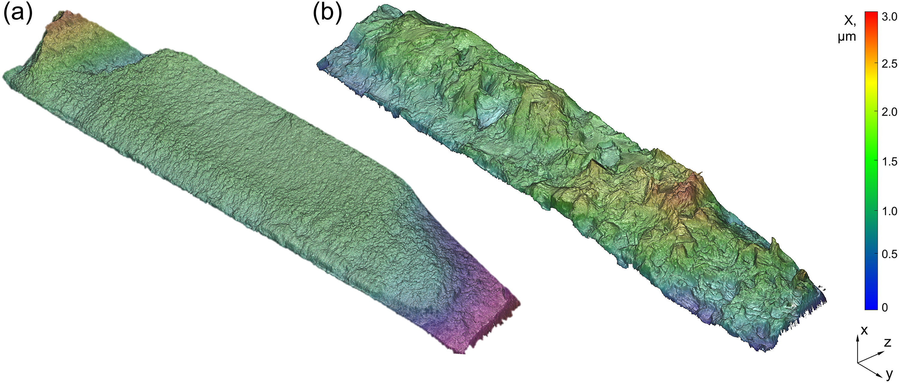
Surface topography maps showing the fracture surfaces of the (a) FAST sub-βt and (b) FAST super-βt Ti-6Al-4V specimens following fatigue failure.
Microscale fracture surface features showing the fatigue crack initiation and propagation behaviour of the FAST sub-βt material are presented in Figure 9. Crack initiation can be seen to have occurred from a single region of faceted primary-α grains (labelled ‘A’ in Figure 9(a)) located just beneath the surface of the specimen subjected to maximum tensile stress. A smooth facet feature is shown in high resolution in Figure 9(b) and shows evidence of formation by transgranular fracture through a primary-α grain. Striated ridges are visible on the smooth facet surface and are indicative of the formation of slip steps, perpendicular to the local crack growth direction, which would have formed during Stage I crack growth. The crack initiation features presented in Figure 9(a) and (b) show resemblance to the smooth crack initiation facets observed for the UDII rolled material shown in Figure 10(a). These observations of transgranular faceting are characteristic of fatigue crack initiation associated with conventional wrought Ti-6Al-4V 40 and the formation of these features can be associated with material separation along slip bands near ‘hard/soft’ neighbouring grain boundary interfaces, as described by the Stroh model. 41 It is notable that no evidence showing any influence of porosity or insufficient powder consolidation on the fatigue crack initiation mechanism.
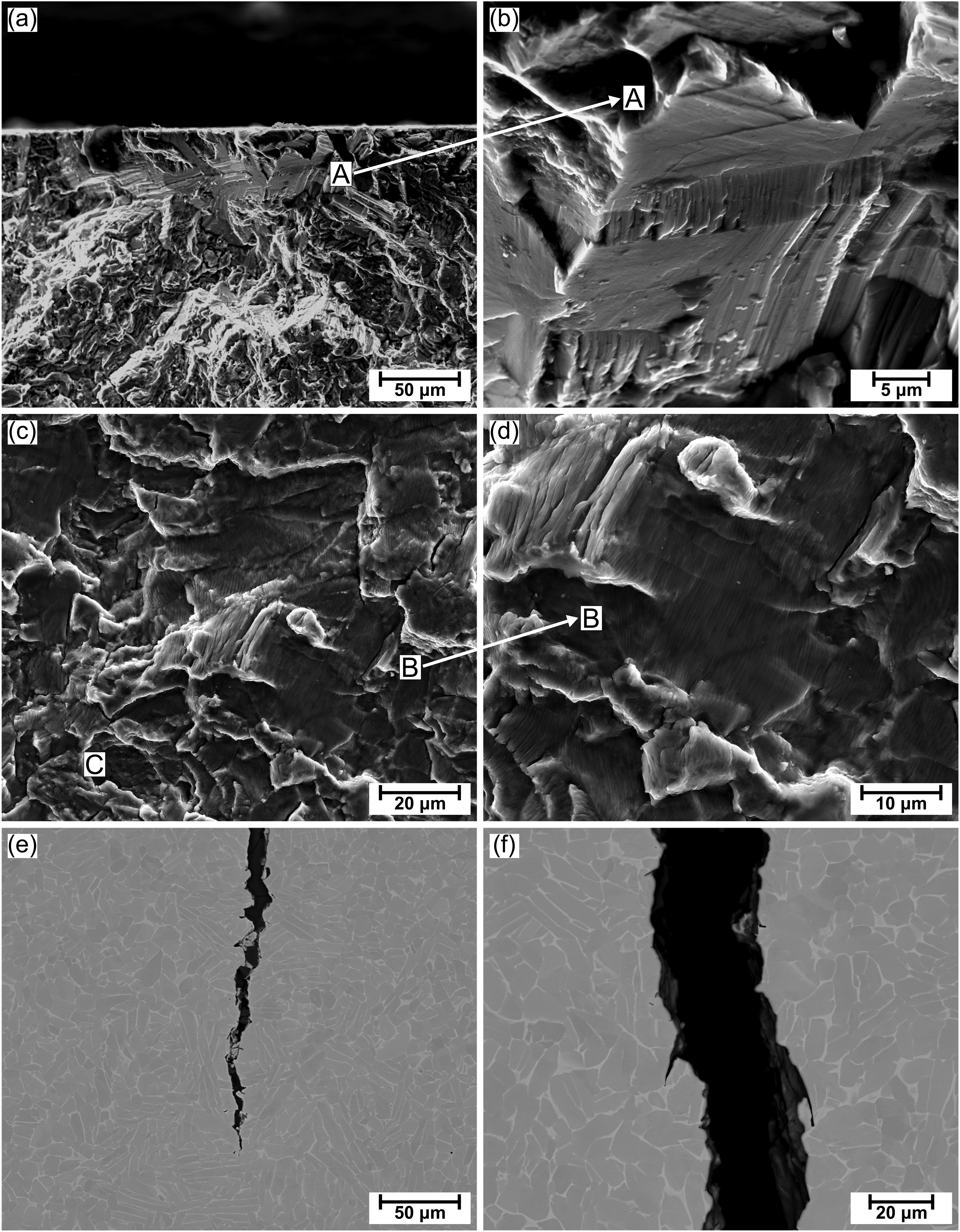
Fracture surface analysis of a FAST sub-βt specimen following fatigue failure. (a) Secondary electron SEM micrograph of the fatigue crack initiation location from a smooth faceted grain, labelled ‘A’, near the subsurface. (b) Higher magnification secondary electron SEM micrograph of the crack initiation facet. (c) Secondary electron SEM micrograph of the fracture surface located in the Stage II crack propagation region. Annotations highlight a striated region, ‘B’, and a monotonic failure region, ‘C’. (d) Higher magnification secondary electron SEM micrograph of the striated region. (e) Backscattered electron SEM micrograph of a secondary, non-fatal, crack in section, revealing a straight crack path through the microstructure. (f) Higher magnification backscattered electron SEM micrograph of the crack path.
Fracture surface analysis of a unidirectionally rolled specimen taken from the orientation parallel to the rolling direction (UDII) following fatigue failure. (a) Secondary electron SEM micrograph of the fatigue crack initiation location from a region of smooth faceted grains, labelled ‘A’, in the subsurface. A machining related surface anomaly, ‘B’ is highlighted. (b) Secondary electron SEM micrograph of the fracture surface located in the Stage II crack propagation region. Annotations highlight a striated region, ‘C’, and a monotonic failure region, ‘D’.
Crack propagation fracture features of the FAST sub-βt material are presented in Figure 9(c) and (d), revealing the presence of striated grains, labelled ‘B’, and monotonic failure regions, labelled ‘C’. The orientation of the striations can be seen to vary from one grain to another, indicating localised misdirection of the crack growth direction. This observation is commonly observed during Stage II crack growth for Ti-6Al-4V 40 and is a result of the influence of the crystallographic orientation of individual grains. This orientation effect alters the preferred crack growth direction to follow slip planes with the highest critically resolved shear stress. In non-striated regions, evidence of monotonic tensile failure is evident by the presence of dimples. In these regions, the crack growth direction has been restricted by the presence of grains possessing an unfavourable orientation for slip. In these instances, the crack path has been diverted around these ‘hard’ orientated grains which has subsequently caused tensile failure of the remaining ligament once sufficient stress has been reached. The combination of striated and monotonic failure regions observed for the FAST sub-βt material can also be observed on the fracture surface of the UDII rolled material in the Stage II crack propagation region, shown in Figure 10(b) and annotated ‘C’ and ‘D’, respectively. These features are on a scale similar to that of those observed for the FAST sub-βt material and correspond to the size of typical α grains. The features observed in both materials are characteristic of the effects of microtexture on fatigue crack growth in Ti-6Al-4V demonstrated in the work by Bantounas et al. 42
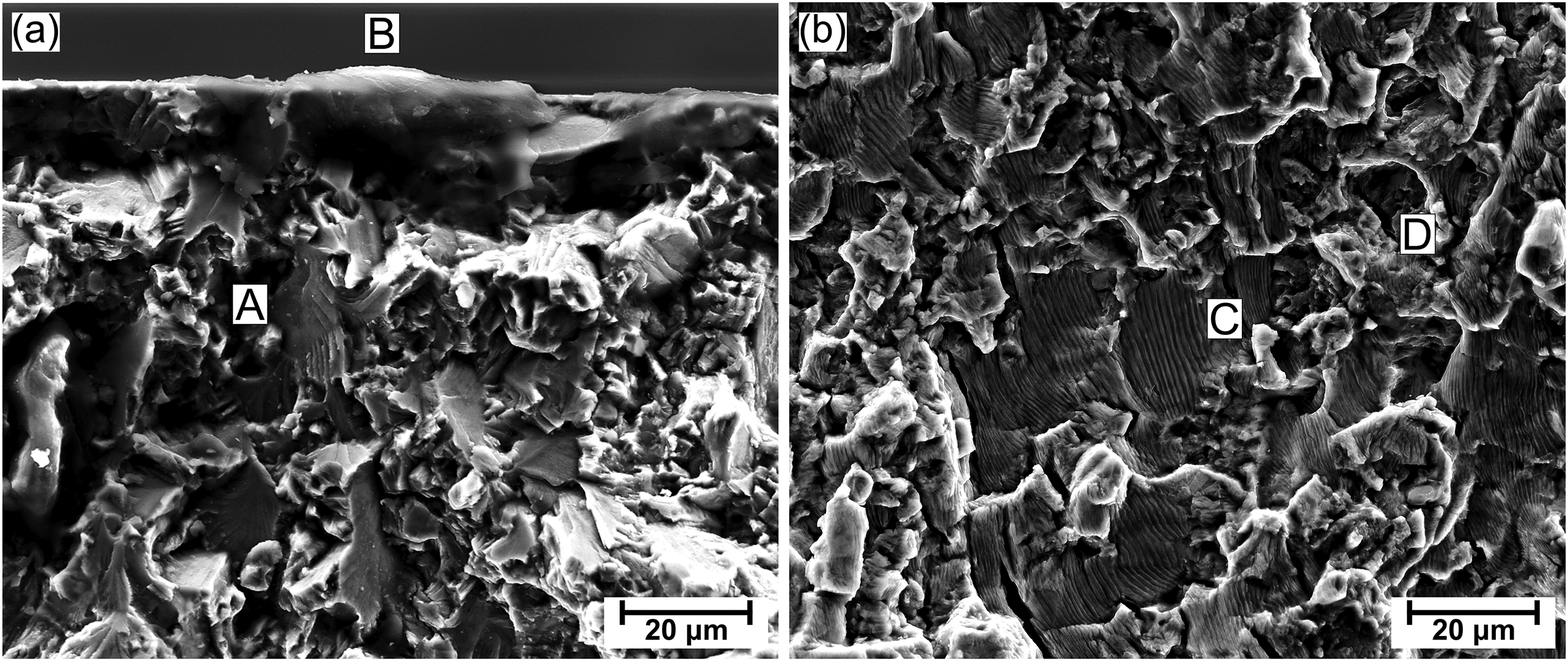
Microscale fracture surface features showing the fatigue crack initiation and propagation behaviour of the FAST super-βt material are presented in Figure 11. Crack initiation for this material condition can be observed to have occurred with a transgranular crack initiated at a prior-β grain located at the sample surface, labelled ‘A’ in Figure 11(a). In this instance, crack initiation has occurred from a chamfer surface of the fatigue specimen, adjacent to the surface of the specimen subjected to maximum tensile stress. As identical machining conditions were employed during the generation of the chamfer and non-chamfer surfaces of the fatigue specimens, it is not expected that crack initiation at this location is a result of variability in the machining-induced surface integrity characteristics of the material at different surface locations. In the region of the fracture surface associated with crack propagation (Figure 11(b)), striated (‘C’ in Figure 11(b) and (c)) and monotonic failure (‘B’ in Figure 11(b) and (d)) regions are again evident, however in this instance they occur over a much larger scale corresponding to that of the prior-β grain size. Similar to the FAST sub-βt material, no evidence of the influence of porosity or insufficient powder consolidation on crack initiation and growth behaviour is evident.
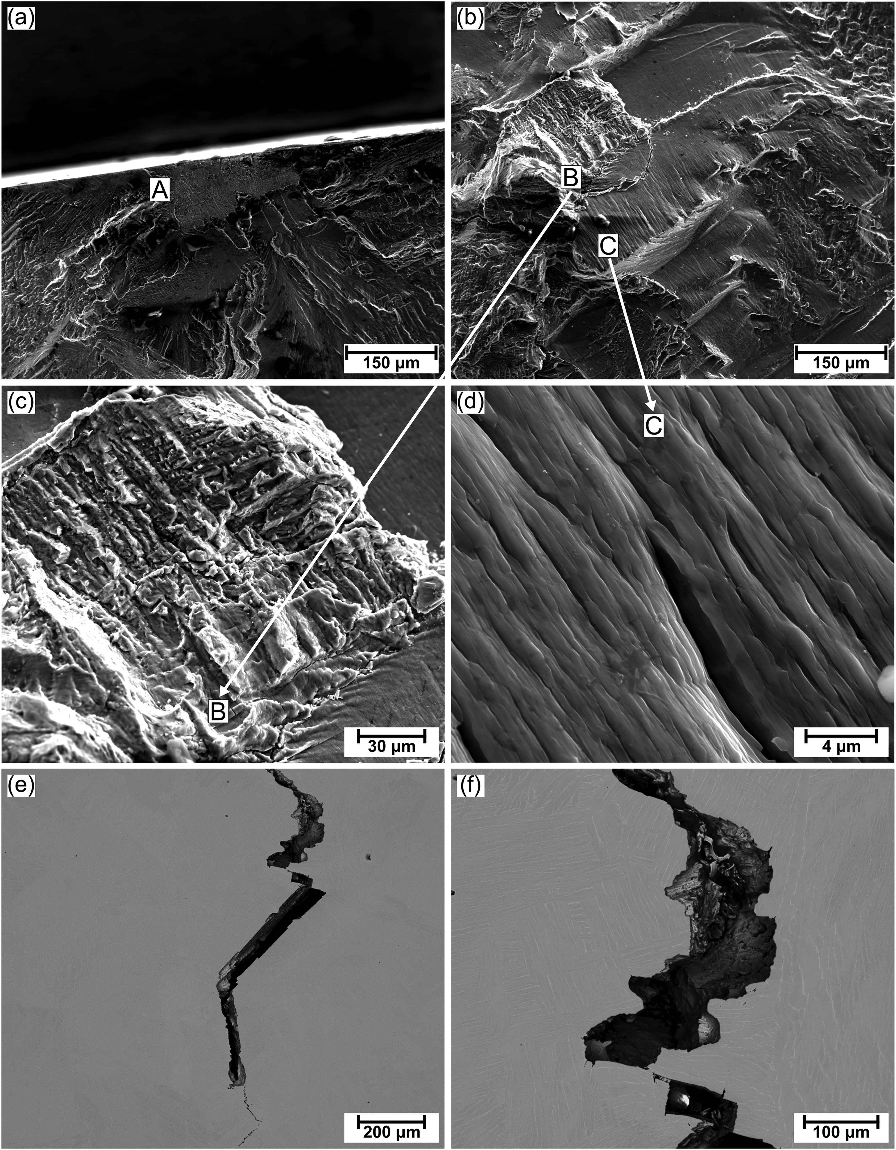
Fracture surface analysis of a FAST super-βt specimen following fatigue failure. (a) Secondary electron SEM micrograph of the fatigue crack initiation location from a faceted prior-β grain, labelled ‘A’, located at the chamfer surface. (b) Secondary electron SEM micrograph of the fracture surface located in the Stage II crack propagation region. Annotations highlight a monotonic failure region, ‘B’, and a striated region, ‘C’. (c) Higher magnification secondary electron SEM micrograph of the monotonic failure region. (d) Higher magnification secondary electron SEM micrograph of the striated region. (e) Backscattered electron SEM micrograph of a secondary, non-fatal, crack in section, revealing a convoluted crack path through the microstructure. (f) Higher magnification backscattered electron SEM micrograph of the crack path highlighting redirection of the crack path as it encounters differently orientated α colonies.
To investigate the crack path direction with respect to the material microstructure, secondary (i.e., non-fatal) cracks were located away from the critical crack for the two FAST material conditions and analysed in section, following metallurgical preparation to reveal the grain structure. For each material, transgranular crack growth can be observed, however, the crack direction for the sub-βt material, shown in Figure 9(e) and (f), follows a straight path compared to the convoluted crack path displayed by the super-βt material, shown in Figure 11(e) and (f). The tortuous crack path observed for the super-βt material condition can be attributed to the orientation of α colonies which influence redirection of the crack as it encounters crystallographic planes unfavourably orientated for slip.
The difference in fatigue performance displayed by the FAST material following consolidation at sub-βt and super-βt conditions can be explained by considering the influence of the different microstructures on the fatigue cycles consumed during crack initiation and growth. The sub-βt processed material possesses a fine equiaxed primary α grain structure which provides improved yield strength and ductility in comparison to the coarse α colony lamellae grain structure of the super-βt material, as evidenced by the previous section. Furthermore, due to the absence of large similarly textured α colonies possessed by the super-βt processed material, hard/soft grain interfaces are considerably smaller in scale for the sub-βt material, resulting in lower levels of localised critically resolved shear stresses under fatigue loading. The combination of higher ductility and the absence of large microtextured regions means that the sub-βt material has been able to accommodate greater levels of plastic strain accumulated during cyclic straining through relaxation of the applied stresses. This has provided the sub-βt material with better resistance to crack initiation and early Stage I crack growth, which is highly dependent on microtexture and crystal plasticity at the crack tip. This suggests that the significant increase in fatigue life displayed by the sub-βt material can be attributed predominantly to an increase in the number of cycles consumed during crack initiation, rather than its subsequent propagation.
Comparing the cycles to failure data at SMax = 950 MPa for the FAST sub-βt material to the UD rolled material indicates similar performance of when the rolled material was taken in the less favourable UDT orientation showing only a 6% deficit in fatigue life for the FAST material. For UDII material, this deficit is considerably larger at 46%. These results highlight the significant variation in fatigue life associated with the anisotropy of UD rolled material. It is expected that the fatigue behaviour of FAST material will display considerably less directional dependence due to its very weak texture component. 13 Although further studies should be performed to evaluate any possible influence of crystallographic texture on the fatigue behaviour of FAST material.
Conclusions
Both static and dynamic testing of out-of-specification additive manufacturing Ti-6Al-4V powder consolidated via the solid-state FAST process were successfully undertaken.
Material produced via FAST processing either above or below the β-transus temperature was demonstrated to have values of UTS, σy, and εf that exceed the requirements of ASTM B988–18: Specification for powder metallurgy (PM) titanium alloy structural components.
Furthermore, material from the edge of the sub-βt FAST disc also meets the requirements of ASTM B381–13: Standard Specification for titanium and titanium alloy forgings, although material from the centre of the disc falls just short of this standard due to a 3% decrease in UTS and a 4% decrease in σy.
Initial indications are the fatigue performance compares favourably with conventionally processed Ti-6Al-4V and may also display less anisotropy, but further investigations should be undertaken.
This work establishes that surplus AM powders can be successfully recycled via the one-step FAST process to provide ASTM-grade material that is comparable to melt-wrought material that has gone through over 40 processing steps, which will improve the sustainability credentials of the AM sector.
This work provides further confidence to engineers and designers that FAST-processed Ti-6Al-4V can be used for a range of components under both static and dynamic loading.
Footnotes
Acknowledgments
We wish to acknowledge the support of the Henry Royce Institute for advanced materials for enabling access to FCT HP D250/C FAST facilities at The Royce Discovery Centre at the University of Sheffield; EPSRC Grant Number EP/R00661X/1 and EP/P02470X/1.
Declaration of conflicting interests
The authors declared no potential conflicts of interest with respect to the research, authorship, and/or publication of this article.
Funding
The authors received no financial support for the research, authorship, and/or publication of this article.