
Abstract
Chemical and mechanical fatigue degradation in ceramic materials is generally inconspicuous yet ubiquitous, to the effect that clinical fractures still consist of the main cause of failure in all-ceramic restorations. Implications of this span wide, from a reduced survival prognosis for the affected teeth, including more frequent and increasingly invasive procedural interventions, to the financial burden borne by individuals and health care systems. To suffice as an effective corrective, restoration lifetimes need only to be extended so to outlive the patient. That opens a box of problems from a materials science standpoint, entailing inherent deficiencies of brittle materials to resist mechanical and environmental challenges. Efforts in developing more damage-tolerant and fatigue-resistant restoratives go thus hand in hand with understanding intrinsic mechanisms of crack growth behavior under conditions that simulate the oral environment. Here we developed experiments using size-relevant sharp precracked specimens with controlled size and geometry (truncated semielliptical crack in the surface-crack-in-biaxial-flexure method) to establish a relationship between crack size and strength. The tangent method was used to construct envelopes for the quasi-static resistance curves (R-curves), which served as template for deriving residual cyclic R-curve analogs. By means of experimentally obtained stress–cycle curves, lifetime and fatigue parameters were employed within a mechanistic framework to reveal constitutive toughening mechanisms during subcritical growth under cyclic loading in a wet environment. Using 3 modern dental lithium disilicate glass–ceramics, we demonstrate the extent of R-curve degradation up to a threshold of 10 million cycles (~30 y in service) and draw parallels between the scope of fatigue degradation and the size of the microstructural units responsible for toughening mechanisms in glass–ceramic materials. Our results indicate that larger microstructural elements endow glass–ceramics with a higher reaching quasi-static R-curve at the onset but degrading more rapidly to comparable levels of lithium disilicates having submicrometric and nanometric crystal phases.
Introduction
Typical mechanical testing of materials produces benchmark properties such as strength (σc) and fracture toughness (KI,c) as surrogates of performance in service. Both are unified in classical fracture mechanics postulates by the critical crack size, ac, through √πac, but fail to provide for a full description of the complex fracture process in multiphasic materials (Evans 1990). In composites such as glass–ceramics, however, crystalline phases are typically tougher than the embedding glassy matrix, making for crack encounters with second phases to evolve into toughening mechanisms of high-energy expenditures (Serbena et al. 2015). While growing to a stable zone length behind an extending formerly initial crack, ai (i.e., Δa = a−ai), mechanisms such as crack bridging shield the crack tip stress intensity factor, KI,tip, by an amount KI,sh at each new crack increment, that is, KI,sh(Δa). The applied KI by an external load, KI,appl, is simply the sum of those terms at any point of a > ai—namely,

resulting in an increasing value of KI,appl with increasing crack size, until a becomes critical at a ≥ ac. That ascending curve is the so-called resistance curve, or R-curve, given in KI,R-Δa coordinates, which increases until a potential plateau is installed at a maximum KI, KI,max (Munz 2007). In practical terms, for a crack to keep growing in an R-curve material, increasing amounts of mechanical energy have to be put in the system. This is an extremely desirable material property for dental materials, given that maximum chewing forces do not tend to scale up indefinitely but move around a maximum, whether at lower (physiological) or higher stress levels (pathological regimens). The R-curve increases that threshold farther from the critical level, and nucleated cracks eventually arrest—even if temporarily—prolonging the life span of a restoration.
Now, those high energy-consuming crack-wake bridges—of elastic and frictional character—degrade naturally for critical crack-opening displacements but also vanish at accelerated rates (especially the frictional ones) through periodical crack opening-and-closing events (crack-face interactions), such as under cyclic loading (Kruzic et al. 2005). This is the so-called “true fatigue effect.” The mechanical benefits of R-curves are thus inevitably lost, at least partly, with increasing time in service. Also ubiquitous in glass–ceramics is the susceptibility of glassy phases to stress corrosion–assisted crack growth (SCCG) in the presence of water species (Wiederhorn and Bolz 1970), which induce a cycle-independent, time-dependent crack growth at subcritical applied stress intensity factors (i.e., at KI, appl < KI,c). In the aggregate, those phenomena compound to a substantial degradation of fracture resistance under conditions of the cyclical masticatory stresses in the humid oral environment.
Here we present an approach for constructing fatigue R-curves by combining an indirect method of R-curve assessment and cyclic lifetime experiments on controlled precracked specimens. On the basis of obtained cyclic fatigue parameters and lifetime estimations, fatigue R-curves are derived from quasi-static R-curves, revealing the susceptibility of R-curve degradation for 3 lithium silicate glass–ceramics of wide compositional variations and microstructural features. Based on the known dependency of R-curves on the microstructural size, we hypothesize an akin relationship governing the R-curve degradation.
Materials and Methods
Materials, Sample Preparation, and Mechanical Testing
For each of the 3 lithium (di)silicate materials selected for this investigation (IPS e.max CAD, Ivoclar AG; CEREC Tessera, Dentsply-Sirona; N!CE Straumann; see Fig. 1, Table), 2 sets of samples were prepared. For establishing the relationship between strength and crack size under quasi-static loading, up to 15 specimens per material were prepared having semielliptical surface cracks with varying initial crack sizes ai, from ~50 to ~200 µm, by performing Knoop indentations with loads between 19.6 N and 98 N. For posterior controlled subcritical crack growth experiments under cyclic loading, up to 20 precracked specimens were prepared per material having the same semielliptical crack size resulting from a Knoop indentation of 39.2 N, thereby falling within the range of precrack sizes covered by the quasi-static tests and also during crack growth. Thus, square-shaped specimens of 2-mm thickness were cut from material blocks grinded to a 12-mm × 12-mm cross section and, if necessary, heat-treated according to the manufacturers’ instructions (IPS e.max CAD: 850°C for 7 min; CEREC Tessera: 760°C for 2 min) in a Programat EP 3010 furnace (Ivoclar AG).
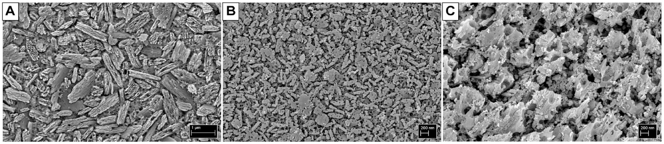
Scanning Electron Microscopy (SEM) images of the tested materials. (
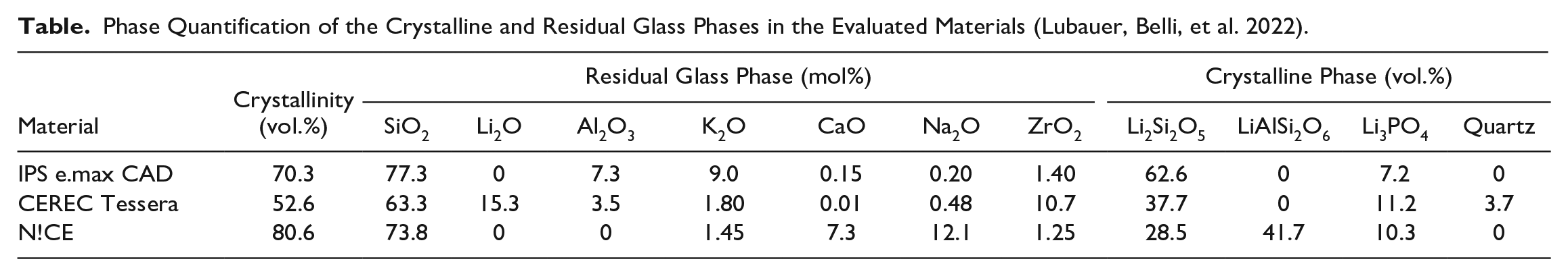
Phase Quantification of the Crystalline and Residual Glass Phases in the Evaluated Materials (Lubauer, Belli, et al. 2022).
The controlled initial semielliptical crack intended to trigger fracture was created by a Knoop indentation applied with a full-load dwell time of 15 s on the bending surface right above the loading ball as determined under a light microscope. In order to remove the damage zone, the residual stress zone, and the lateral cracks induced by indentation, as well as obtain a remaining semielliptical median crack of appropriate geometry (Lubauer, Lohbauer, et al. 2022), the indented surface was polished with a P220 SiC polishing discs (MD Piano 220; Struers) under water irrigation to remove a layer thickness corresponding to 7 to 8 times the depth of the indentation h (with h = d/30 and d being the long diagonal of the indentation). All specimens having the same indentation load were bonded to a polishing plate with a resin wax and polished together in a polishing machine with automated grinding depth control (Tegramin 25; Struers). The polishing depth was double-controlled with a table ball-caliper with a 2-µm resolution to the thickness target, thereby producing sets of specimens containing precracks of the same size. All polishing was undertaken within a maximum 15 min after indentation.
The specimens with varying precrack sizes (for quasi-static tests) were fractured using a custom jig at a 1.5-mm/min loading in air to minimize SCCG, and their individual fracture stress values were calculated using the critical force, Fc (Strobl et al. 2014; Wendler et al. 2017):
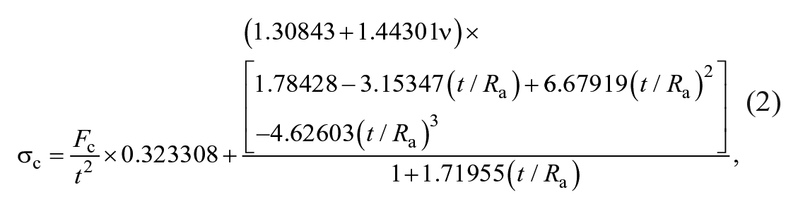
where t is the thickness of the specimen, Ra is the support radius defined by the 3 supporting balls in contact Ra = 2√3 × Rb/3 (Rb = 4 mm is the radius of the supporting balls), and ν is the Poisson’s ratio of the material (Belli et al. 2017; Lubauer, Belli, et al. 2022). The length a and width 2c of the semielliptical preracks were measured postmortem under a stereomicroscope (Discovery V.8; Zeiss) without any staining. Strength values obtained over a wide range of initial crack sizes allow for the construction of stress at fracture (σc) versus initial crack size (ai) plots, from which the existence of an R-curve can be inferred in that specific interval of crack extension (Δa).
Specimens intended for cyclic fatigue testing with the same precrack size (indented with 39.2 N) were loaded in biaxial flexure in a servo-electric testing machine (DYNAdent; Dyna-Mess GmbH) in water at varying subcritical stress levels under sinusoidal cyclic loading (Fett et al. 1991) by adjusting the maximum applied force to different fractions of the initial strength under a stress ratio R = σmin/σmax = 0.3 and frequency f = 15 Hz. The number of cycles to fracture, Nf, were recorded up to a limit of 107 cycles to construct stress–cycle diagrams (σappl – Nf curves), from which the fatigue parameter n could be derived and fracture stresses for specific lifetimes estimated.
Results
The relationship between strength and size of the semielliptical median precracks was obtained for each material by constructing a log–log plot, with a least squares linear regression over all data points:

illustrated in Figure 2 (upper row) with 95% confidence bands. The deviation of the slope of the curve (ξ) from −1/2 indicates a behavior diverging from a constant critical stress intensity fracture KI,c at the moment of crack extension (Δa > 0) (Fett and Munz 2000). The intervals (see Figure 2) do not contain the term −0.5, implying that all values of ξ differed significantly from −1/2 and that an R-curve effect is present in all of the 3 materials.
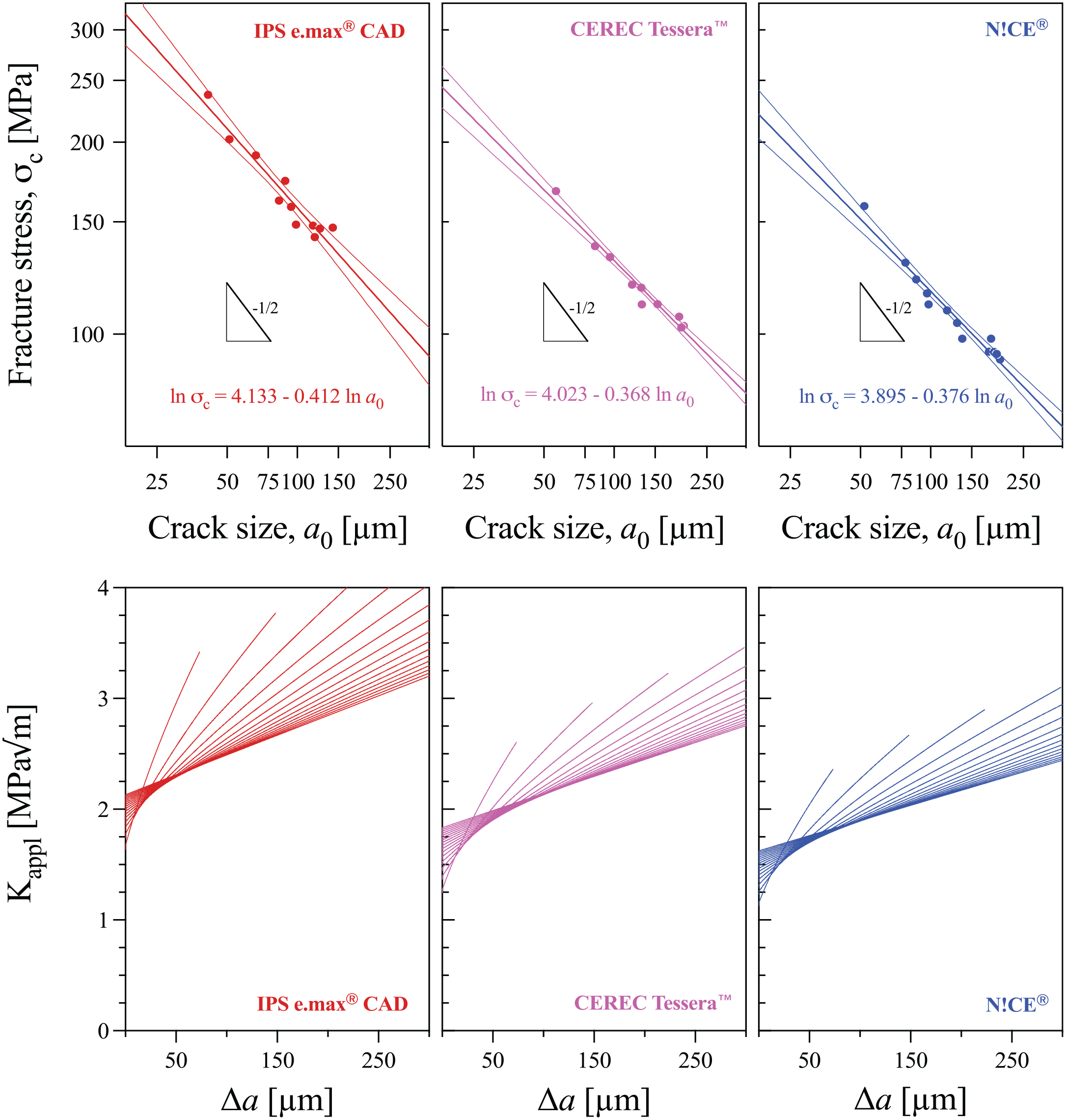
Data for the relationship between initial crack size and strength. Upper row: logarithmic plots of strength versus initial crack size, with the slopes of the curves differing significantly from −1/2. Lower row: constructed KI,appl = f(σc, ai) curves using equations (3) and (5).
The shape of the R-curve, at first inconspicuous, can be revealed by computing the applied stress intensity factor KI,appl = f(σc, ai) during the region of stress buildup where the crack is stationary (a = ai and Δa = 0) toward beyond the value of crack criticality ac (at some Δa > 0), at which the KI,appl = f(σc, ai) becomes tangent to the R-curve, KI,R(Δa)—namely, the tangent condition is met:

This is the moment of fracture; the projection to the ordinate is the nominal KI,c in a quasi-static test. Using σc taken from equation (3) and ai as a parameter, several KI,appl curves can be computed for increasing initial crack sizes ai,j:
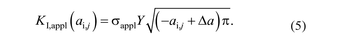
We modeled a linear increase in Y with increasing crack size and decreasing a/c ratio from our observations in crack shape change in Lubauer, Lohbauer, et al. (2022). Equation (5) makes for the individual curves in Figure 2 (lower row) (plotted here in 25-µm ai increments), which intersect at increasing values of crack extension Δa with increasingly higher ai, giving the polygonal envelope of the R-curve (Fett and Munz 2000; Fünfschilling et al. 2010). The R-curve can thus be constructed by connecting the midsection points of KI,appl(ai,j) segments between subsequent KI,appl(ai,j) intersection points. Those tangent points give the darker contour resulting from the superposition of the individual KI,appl(ai,j) curves seen in Figure 2 (lower row).
The results of the subcritical crack growth experiments under cyclic loading are depicted in Figure 3 in a log–log plot of (σappl vs. Nf) in which the slope is −1/n. The cyclic fatigue parameter n yielded statistically similar values for all 3 materials (determined by the overlap of the 95% confidence interval bands), despite the tendency of a slightly lower slope for IPS e.max CAD. Here, lifetimes can be estimated for individual materials, but comparisons are prohibitive due to the different initial crack sizes (despite the same load, median Knoop cracks grow to different sizes due to material-dependent factors, such as residual stresses). The σappl versus Nf curves in Figure 3 can now be used for obtaining the residual strengths (i.e., the σappl,c after specific cycling intervals), which provide the critical crack size as transferred from the tangent point between KI,appl = f(σappl,c) and the original quasi-static R-curve. From there, a fatigue R-curve can be derived, as discussed below.
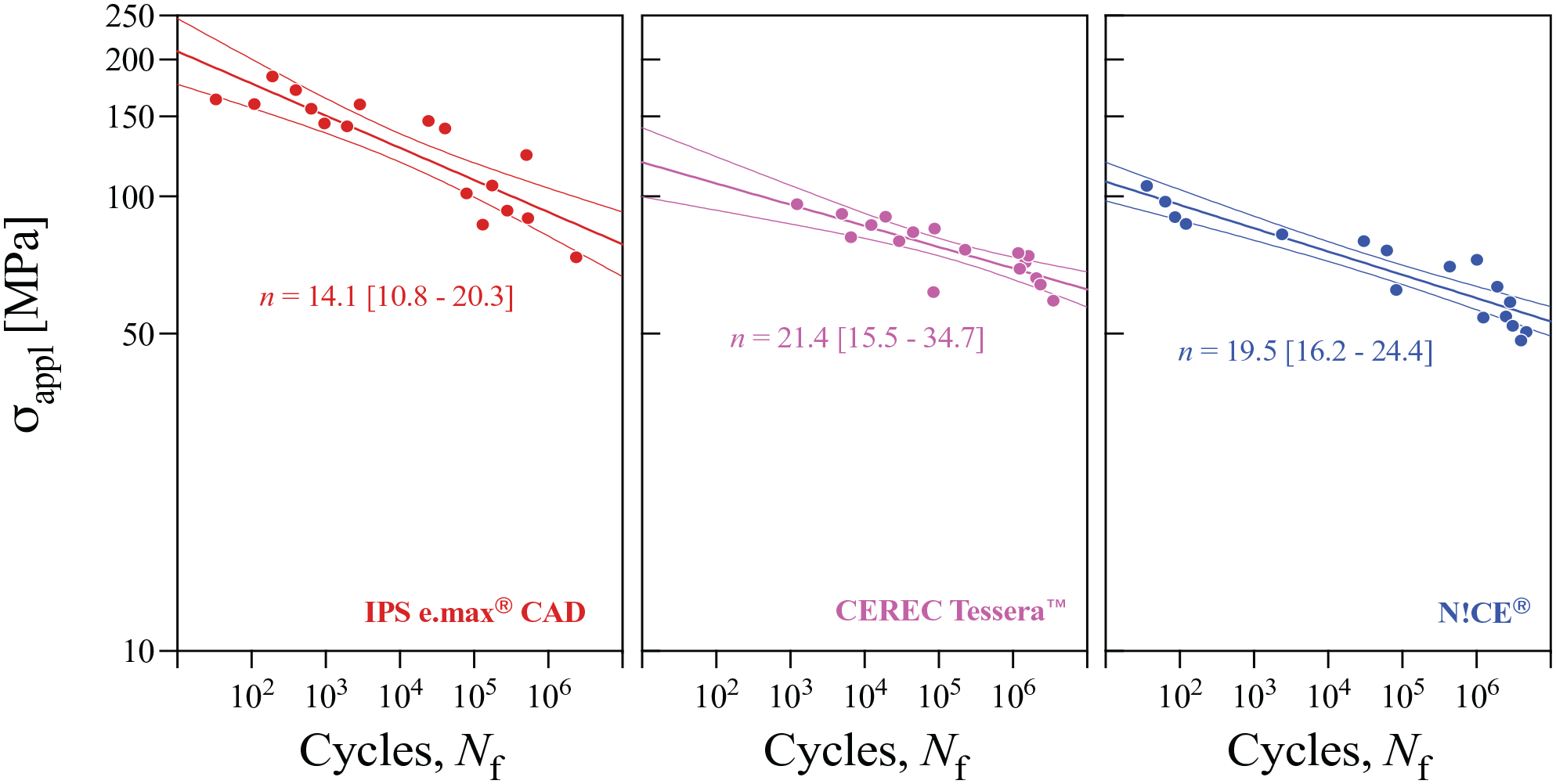
Logarithmic plots of maximum applied stress σappl versus number of cycles Nf. The slope gives the fatigue parameter n through −1/n, obtained from the least squares regression with 95% confidence intervals.
Discussion
The quasi-static R-curves obtained from the polygonal envelopes of KI,appl(ai,j) in Figure 2 are illustrated in Figure 4 as the upper solid lines, fitted by a function KI,R, N = 1 = KI,0, N = 1 + CΔam. The curves were fitted retrogradely to a starting point when the crack started to extend subcritically, described as KI,0. In composites such as glass–ceramics, the crack grows first from the glass since it exhibits the lowest KI,c, with KI,R rising steeply as the crack encounters the first crystals (Fett 2012). Here we defined the value of KI,0 for all 3 composites as equivalent to the KI,c of a glass we synthesized by melting (2 h at 1,450°C), quenching (2× splat-cooling), and annealing (16 h at 400°C), having the binary composition 25 mol% Li2O and 75 mol% SiO2, corresponding to a SiO2/Li2O ratio of 2.5, similar to the base glasses of all 3 glass–ceramics (Lubauer, Belli, et al. 2022). 1 Measured using the same B3B-KI,c method in discs, the obtained KI,c was 0.89 ± 0.08 MPa√m, taken as the common point of the R-curve departure, which rose more steeply in the first 50 µm for IPS e.max CAD, followed by CEREC Tessera, with N!CE showing the lowest rise during this stage. Along with KI,0, the shape of the R-curve is given by the parameters in equation (2); the higher the ξ, for instance, the more closely packed the KI,appl(ai,j) curves are (see the range in which the lines cross the y-axis) and less steeply the R-curve continues to rise at later stages of crack extensions (>50 µm), here with IPS e.max CAD as an example.
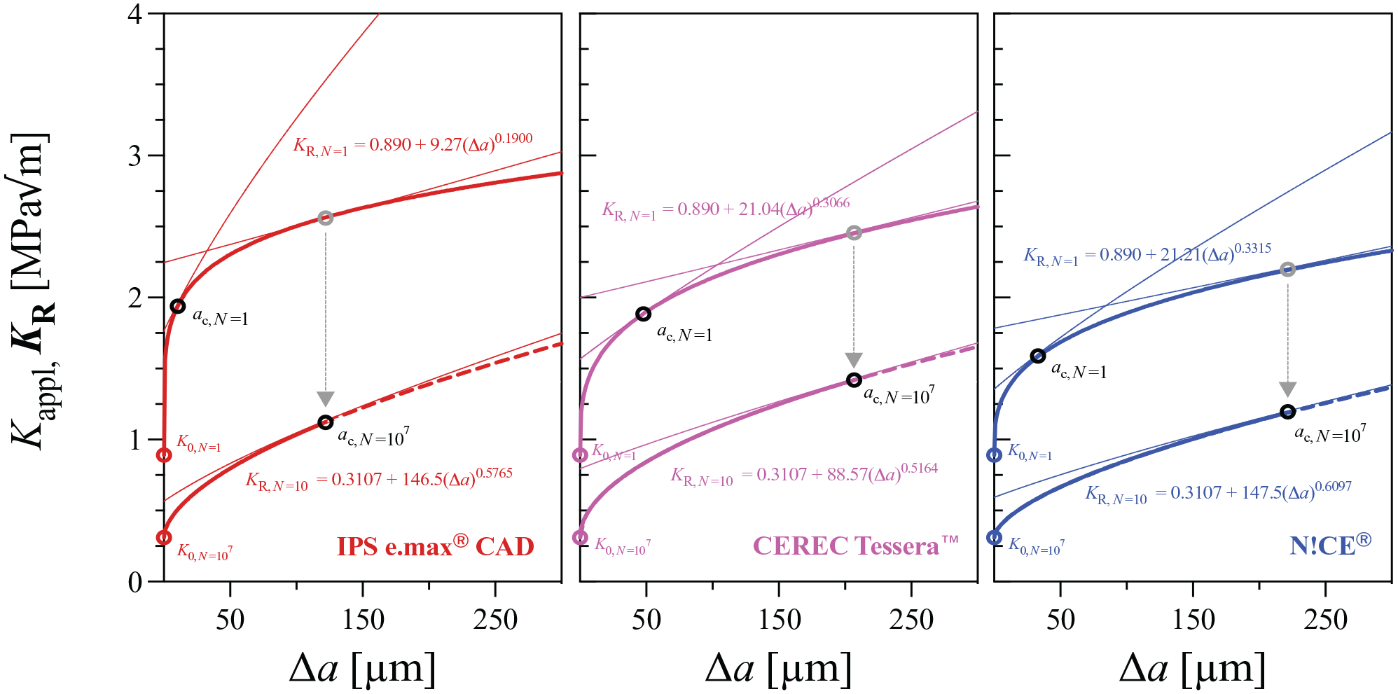
Constructed quasi-static KI,R(Δa) curves from the polygonal envelopes in Figure 2 (lower row) and the resulting fatigue KI,R(Δa) curves after 107 cycles. The dashed lines are extensions of the fitted solid lines.
The scope of the degradation of the quasi-static R-curves is revealed in Figure 4 by constructing fatigue R-curves after 107 cycles. Assuming normal chewing habits to amount to about 1,000 cycles per day (Kelly 1997), our 107 cycles would represent a time span of ~27 y. The values of strength after 107 cycles were obtained by the extrapolation of the σappl versus Nf curves (Fig. 2), inserted in equation (2) to obtain the value of ai, which was then used to build a KI,appl(ai) curve that would reveal the critical crack size for that value of strength in the absence of degradation, by means of the tangent point with the quasi-static R-curve (gray circles in Fig. 3). That tangent point corresponds to the critical crack size (the moment of fracture) at 107 cycles,
Under subcritical stress in water, the KI,0 of the residual glass is also poised to be reduced due to SCCG, acting concomitantly to the degradation of the friction acting in KI,sh (true fatigue effect). Thus, in bridging ceramics, the n-value under cyclic loading must be lowered relative to the static condition, as demonstrated for IPS e.max CAD by Zhang et al. (2019) in direct measurements and in Kirsten et al. (2020) indirectly. Although in glasses, the fatigue n-parameter under static and cyclic loading is expected to be equivalent (Fett 1993; Munz and Fett 1999),
2
we estimated the KI,0 at a lifetime, tc, for 107 cycles from our static fatigue experiments in our synthesized LS2.5 glass precracked specimens (i.e., tc = Nf/f), which amounted to 0.310 MPa√m. The fatigue R-curves (lower curves in Fig. 4) were then fitted to the same function (i.e., KI,R, N = 107 = KI,0, N = 107 + CΔam), forcing it to be tangent to KI,appl(ai) at
The primary realization here—one that is not trivial—is that a persistent residual R-curve exists for all materials after long cycling regimens. The slope of the fatigue R-curve at 107 cycles loses its marked initial steepness and acquires a shape more akin to a single slope, almost parallel to the later stage (at longer Δa, where the bridging zone has already matured) of the parent quasi-static R-curve. As degradation advances, the initial steep stage when the bridging zone would still be increasing in size now gets severely compromised, and the bridging zone becomes stable at shorter zone lengths. This is because bridges are degraded at the wake of the crack due to frictional loss at higher rates than when they would degrade naturally from a critical crack-opening displacement (as during the quasi-static R-curve). The repetitive sliding of crack faces and bridge interfaces then diminishes the initial friction coefficient µi, following an exponential dependency to the number of cycles, N, as proposed by Fett et al. (2005):

with N0 being a characteristic number of cycles. The reduction of tractions at bridging elements is therefore cycle dependent, and thus KI,sh(N) = KI,sh exp(−N/N0), which also depends on KI,appl,max and the R-ratio. Yet, this process is still concomitant to new bridges being created at the crack front whenever the crack advances subcritically (Kruzic et al. 2005; Fett 2012; Hartelt et al. 2013; Greene et al. 2014).
When comparing the 3 materials, it becomes clear that the fatigue threshold R-curves for 107 cycles are equivalent in shape within error for IPS e.max CAD and CEREC Tessera; a comparatively flatter ascend was obtained for N!CE. However, the truly important phenomenon to be underscored is the degradation of the quasi-static R-curve, that is, the shift from the upper to the lower curve in Figure 4. That drop is substantially more acute for IPS e.max CAD while less severe and seemingly comparable for CEREC Tessera and N!CE. This is by no means unintuitive. Bridging degradation tends to be more exacerbated for microstructures that induce more marked bridging events, as when particles are larger and more elongated (Foulk et al. 2007; Sabino et al. 2022; Senk et al. 2023). This has been shown experimentally for 2 lithium disilicates in Kirsten et al. (2020), where the one exhibiting elongated 5-µm-long Li2Si2O5 crystals showed more extensive cyclic fatigue degradation than the one having Li2Si2O5 of 1 µm in size of a lower aspect ratio, irrespective of test frequency and R-ratio. The stress biaxiality in the B3B also decreases the R-curve by decreasing the tractions orthogonal to the bridge elements (Fett 2012), evidenced by the lower quasi-static R-curve obtained here for IPS e.max CAD compared to that obtained under uniaxial bending in Lubauer, Ast, et al. (2022). For our investigated materials, the rule “the more bridging the more degradation, the less bridging the less degradation” seems to hold insofar as the microstructural size is concerned.
However apparent, based solely on the extent of R-curve degradation observed here, ceramics with larger crystal sizes are expected to present lower fracture rates at earlier lifetimes due to their higher strength and steeper R-curve (Kruzic et al. 2005; Greene et al. 2013, 2014), with fracture rates converging at later stages with those of nanostructured materials. This has been known for structural ceramics for some time now. Clinical data seem to support that initial trend (Belli et al. 2016), despite the general lack of data on the end tail of clinical survival curves for dental ceramics. In practical terms, the cumulative survival would still probably be higher for ceramics with larger microstructures that induce steeper and higher-reaching R-curves at any point along the life span of a restoration, with lithium silicates with submicrometric and nanosized crystals suffering especially from higher initial fracture rates.
Conclusions
We demonstrated here that larger microstructural units in lithium disilicate glass–ceramics positively affect their quasi-static R-curve development while suffering from increased R-curve degradation during cyclic loading by progressive loss in frictional stresses inherent of bridging mechanisms. At longer lifetimes, the extent of the residual R-curve during subcritical crack extension reaches comparable levels for both micrometric and submicrometric crystalline microstructures.
Author Contributions
J. Lubauer, U. Lohbauer, contributed to data acquisition, analysis and interpretation, drafted and critically revised the manuscript; R. Belli, contributed to conception and design, data acquisition, analysis and interpretation, drafted and critically revised the manuscript. All authors gave the final approval and agree to be accountable for all aspects of the work.
Footnotes
Acknowledgements
The authors thank the support of M. Schwarz in the supervision of the extensive fatigue experiments.
Declaration of Conflicting Interests
The authors declared the following potential conflicts of interest with respect to the research, authorship, and/or publication of this article: All materials used in this study were donated by the manufacturers. The authors declare that they have no known competing financial interests or personal relationships that could have appeared to influence the work reported in this article.
Funding
The authors received no financial support for the research, authorship, and/or publication of this article.