
Abstract
Residual deformations caused by processing, such as spring-in and warpage, pose a significant risk to the production of high-performance composite components, especially in aerospace applications given tight tolerances. Capturing stress gradients through thickness caused by differential thermal and cure shrinkage strains requires detailed process modeling, which is computationally demanding and extensive materials characterization needs to be performed. Thus, threshold values for considering a laminate as ‘thick’ are targeting. To determine the critical lower thickness limit at which cure gradient-induced warpage becomes significant, a finite differences-based process model was validated by comparing it with finite element process simulation results. A comprehensive parameter study, based on a full factorial design of virtual processing experiments, was conducted to evaluate estimated rigging loads across three different material systems, various tooling configurations and thermal boundary conditions. Manually applicable moment fluxes were estimated and compared to those calculated required to bend back the laminate after processing. While for standard aerospace processing conditions, the rule of thumb of 20 mm laminate thickness was confirmed, on particularly asymmetric tooling and thermal boundary conditions, the thickness criterion was observed to be as low as 10 mm.
Keywords
Introduction
Curing of carbon fiber reinforced plastics (CFRP) laminates exceeding a certain thickness poses a challenge to identifying a suitable temperature cycle: owing to the low thermal conductivity of the composite, especially through-thickness, in conjunction with the heat of reaction released as the crosslinking of the thermoset takes place, exotherms arise resulting in a distinct temperature gradient through thickness.1–5 Consequently, gradients in the cure state are present through thickness and differences in the transition between morphological phases, i.e. their spatial timing, lead to residual stress and warpage. Besides, degradation of the matrix due to temperature overshoots may be of concern regarding the mechanical performance of the matrix 6 or may yield even to process induced cracking and delamination within the laminate after cure. 3
Exotherm and temperature inhomogeneity during processing of thick laminates has been addressed for instance by Rasekh 1 : he proposed modified Heisler charts based on closed form solutions for the heat transport in laminates with temperature boundary conditions to quickly estimate the maximum temperature difference expected during processing. Utilization of classical lamination theory (CLT) in conjunction with a finite differences (FD) scheme to solve the heat conduction equation through-thickness to predict process induced strains features a considerable history. CLT relates normal loads and bending moments to membrane strains and curvatures with the kinematics of a Kirchhoff shell. Hahn and Pagano, 7 notably early work from mid 1970s, introduced a modulus in fiber transverse direction linearly varying with temperature and estimated the residual stresses based on CLT. Conducting an analysis of the cool down portion only, they used an “incremental strain theory” with increments of approximately 28°C, thus effectively an incrementally linear elastic model was utilized. Other researchers have picked up the idea of incrementally analyzing the mechanical response of the curing composite during processing with CLT, utilizing a finite differences scheme in conjunction with a finite volume approach for both the thermal and cure analysis. Bogetti and Gillespie 2 were pioneering in the field of analyzing the curing of thick laminates, later Ruiz and Trochu 3 addressed different curing conditions, e.g. inside/out, in a structured way for a resin transfer molding processing technology. While not addressing the temperature and degree of cure gradient through thickness, White and Hahn imposed a boundary condition of zero membrane loads and curvatures to account for the tool constraint during processing. 4 They evaluated the in-plain strains and the resultant laminate moments on their asymmetric laminate strips setting normal (membrane) loads and curvatures to zero. Validating their model with residual curvature measurements on partially cured samples, they found good agreement between model predictions and experimental readings for degrees of cure (DOC) bigger than 0.9. 5 Also, Bogetti and Gillespie validated their model predictions with data from literature and found good agreement for samples where the cure cycle had been interrupted during the final hold. 2 Ruiz and Trochu re-heated cured samples above their glass transition temperature and compared the measured curvature progression during cool down with numerical results. 3 While most of the work, particularly 2 and, 3 focused on residual stress quantification of thick laminates, validation of modeling routines has been carried out exclusively on thin laminates ranging from 2 plies 3 to 8 plies (1 mm)2,5. Thus, the results of the process simulation results have been validated on thin laminates, but the modeling procedure has been applied on and therefore extrapolated to thick laminates.
Furthermore, the definition of a laminate being thick is unclear: Ruiz and Trochu inferred that the laminates they investigated with a thickness of 15 mm are relevant for cure gradient induced residual stresses. Bogetti and Gillespie virtually processed laminates of thicknesses ranging from 13.8 mm to 76.2 mm, suggesting that the former value was regarded as a lower bound in terms of relevance. Several studies have focused on optimizing the cure cycle towards minimizing temperature gradients and exotherm8–11. Secord et al. 10 formulated a modified Damköhler number deducted from the ratio of reaction to conduction time scales, where, for instance, the Springer-Tsai equation may be used to calculate fiber transverse conductivity on composite level 12 . Applying this criterion, i.e. the modified Damköhler number to assume one, values of approximately 15 mm to 20 mm indicating laminates as “thermally thick” result.
Process induced deformations (PID) stemming from cure gradients in composite laminates as a single mechanism have not been addressed extensively in literature. In addition, a limit value for considering resulting clamp-up forces as critical, is lacking. The study at hand closes this gap in bounding categories of laminates being regarded “thick” categorizing the impact of expected deformations in terms of normalized clamp-up moments.
To do so, a finite differences scheme is implemented to model relevant physics during processing. After validating the model with a current state of the art process simulation platform, a parameter study is presented to cover various tooling configurations and material systems. The critical thickness of the laminates is identified based on the limit of manually applicable clamping forces to reverse the deformation.
Implementation of a numerical model
In the following, a brief description of the implementation and validation of a 1D (through-thickness) finite differences model utilized as a virtual test bench is presented.2–4,8,10,11
Heat transfer and cure modelling
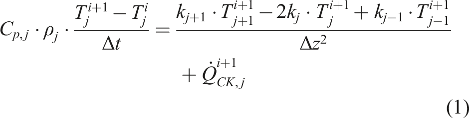
The Fourier heat conduction equation (1D) has been solved for the temperature field through thickness using an implicit backward scheme in conjunction with a finite volume approach similar to2,3
The volumetric heat flow term

Formulating the degree of cure based on the cure rate equation (cure kinetics) implicitly is complicated even for the simplest models,
13
thus an explicit forward scheme is practically always to be used. Here, due to the moderate curvature of the solution curve

As the cure rate and temperature are coupled, this results in the situation that even though the temperature can be solved for implicitly, typically several iterations are necessary per time step to improve the accuracy of the cure rate and degree of cure estimates. 13
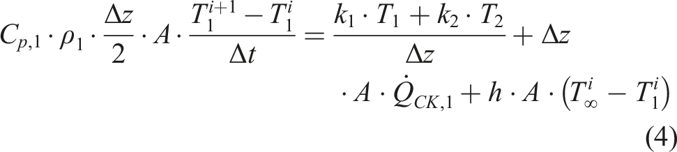
The energy balance needs to be formulated at external boundaries in terms of the balance of heat flows incorporating convective heat transfer, exemplarily for
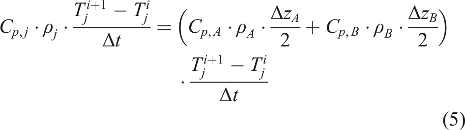
At internal boundaries between neighboring material domains, temperature equality is considered as
An incremental mechanical analysis was implemented based on CLT2,4. The temperature distribution through thickness from thermal analysis is interpolated linearly between summation points (grid) cf. Figure 1. To simplify the strain compatibility evaluation for the plies in terms of virtual loads, i.e. no bending strains, a constant temperature is calculated for each ply as the average of the respective interpolated temperature progression. This results in a minimum of 24 temperature values through thickness for the thinnest laminate investigated with 4.8 mm thickness and a single lamina thickness of 0.2 mm. Schematic of mechanical quantities approximation during an increment of mechanical analysis.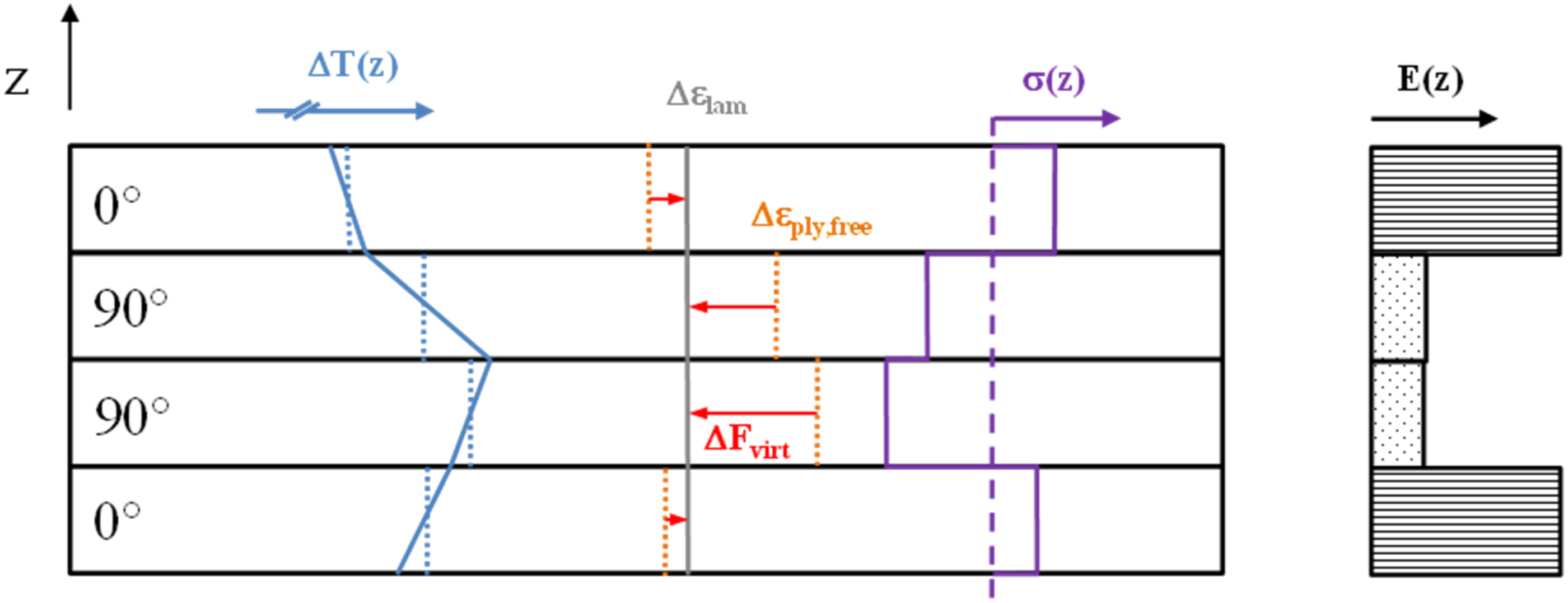
The manufacturing tooling is assumed to impose a pressure load on the curing laminate ensuring planarity of the laminate during processing. Simplifying the problem with CLT, appropriate modeling of these boundary conditions (BC) is needed. Contrary to setting curvature components to zero as applied by White and Hahn,
4
resultant laminate loads are imposed: After calculating the virtual laminate loads resulting from restrained expansion/contraction of the single ply compliant with the laminate strain state, “boundary condition” moment fluxes are calculated yielding a curvature free laminate during processing:
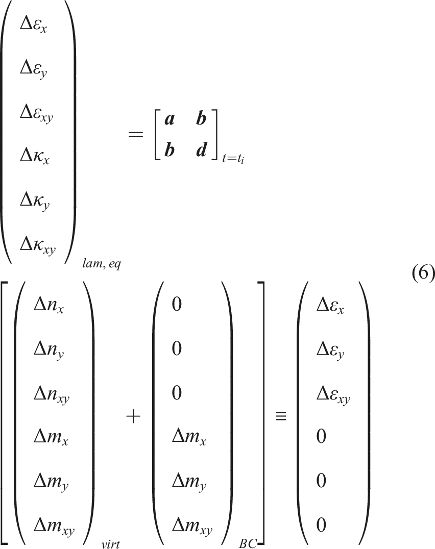
To calculate the deformation of the laminate after processing, the cumulated incremental boundary moments are released, i.e. applied on the laminate with the opposite sign to model the tool removal step:
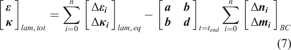
The boundary moments at the end of the cure cycle prior to de-molding represent the fluxes to keep the laminate flat. Thus, these loads have been evaluated about the mounting situation, i.e. compared to a limit value considered a lower bound for criticality.
Adapted from a maximum expected change in mechanical properties, a constant time increment of 50 s was set for the mechanical analysis. In Appendix B a flow chart of the implementation is presented.
Validation
A validation campaign has been carried out to verify the model predictions on increasing levels of detail of the problem, ensuring traceability of root causes for possible deviations. The following steps have been taken. (1) 0D analysis verification: comparison of temperature and degree of cure dependent resin and ply properties. (2) 1D heat transfer validation: convergence study and comparison to Abaqus/CCA15,16 solution. (3) 2D cool down analyses (constant material properties): constrained resultant moments, strains for free deformation case and laminate stress-strain-state for both configurations; comparison to EsaComp
17
results and results from linear-elastic Abaqus simulations utilizing shell elements. (4) 3D virtual processing of thin laminates (0.8 mm and 1.6 mm) as well as representative setups taken from the parametric study: comparison of residual curvature results between code implemented in Matlab and Compro/CCA predictions.
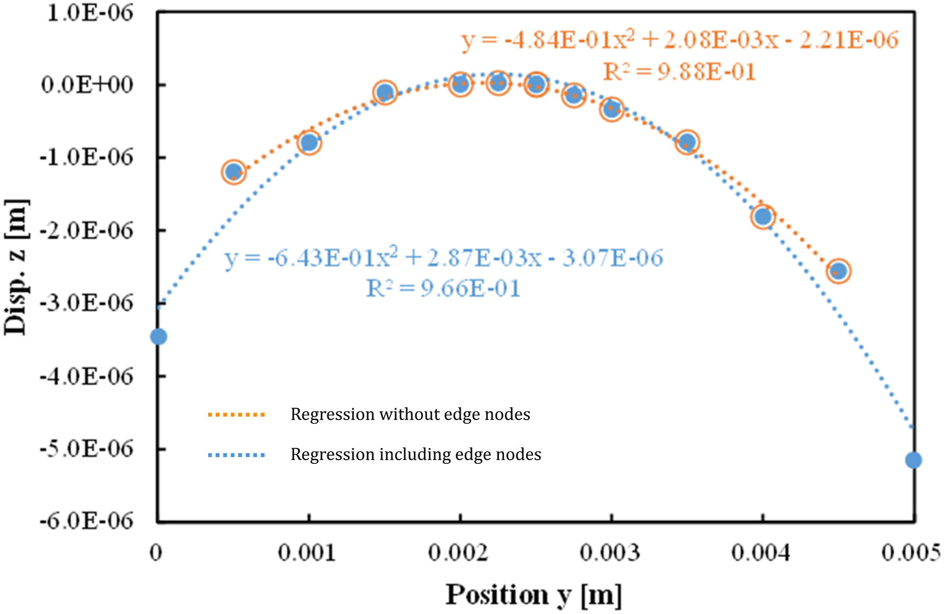
Validation steps 1) through 3) are presented in Appendix C.1. For validation step 4), various laminates with different stacking sequences had been virtually processed and results from the Matlab routine were compared to Abaqus/CCA results. Analysis findings for two relatively thin laminates utilizing the aerospace grade prepreg (AGP) material system with stacking sequences [0/90]2 and [0/-45/45/90]s are presented here. Models have been subjected to a temperature boundary condition (1-hold cycle) utilizing Abaqus/CCA and a one element per ply discretization (C3D20R). In Figure 2 the deformed shape of the asymmetric 4-ply laminate is shown. “Bulging” of the elements is attributed to edge effects, which are also apparent when plotting the displacement in z-direction along x- and particularly in y-direction, cf. Figure 3. For the quantification of a representative curvature values from finite element analysis (FEA), quadratic regressions were used omitting the edge nodes where these effects were dominant. Deformed plot of [0/90]2 laminate after de-tooling. Left: bottom view. Right: top view. Deformation scale factor: 30. Z-displacement in y-direction for [0/90]2 laminate after de-tooling (FEA results) including curve fitting.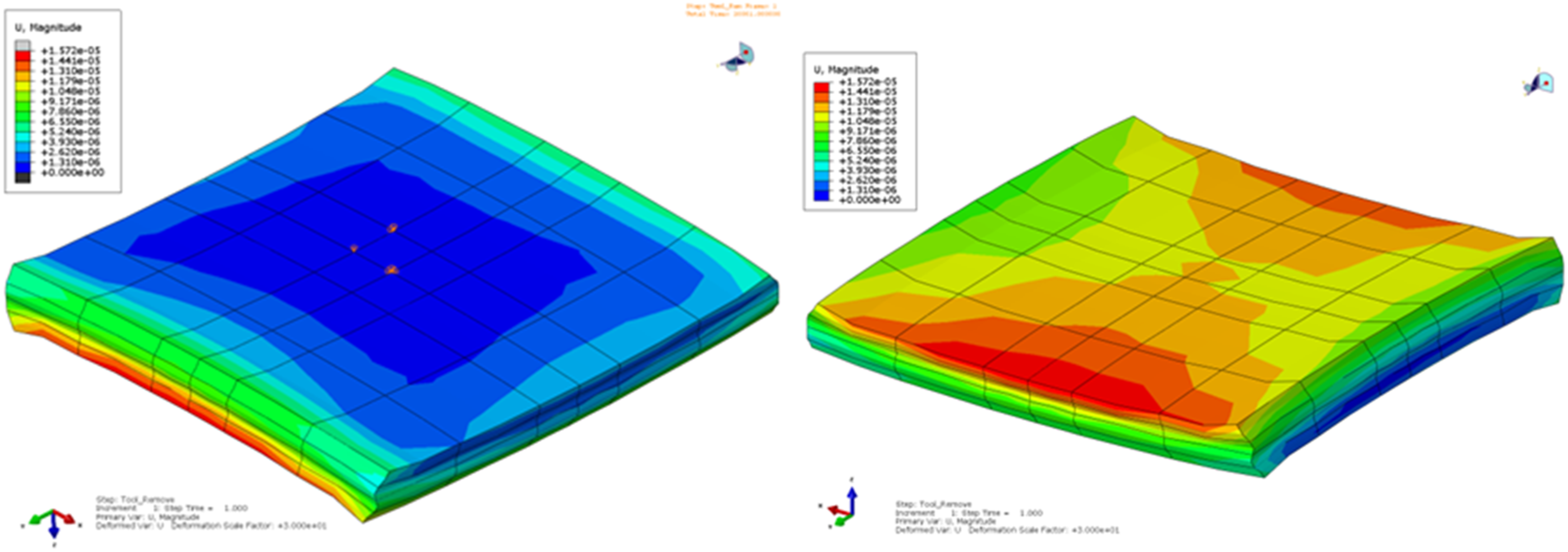
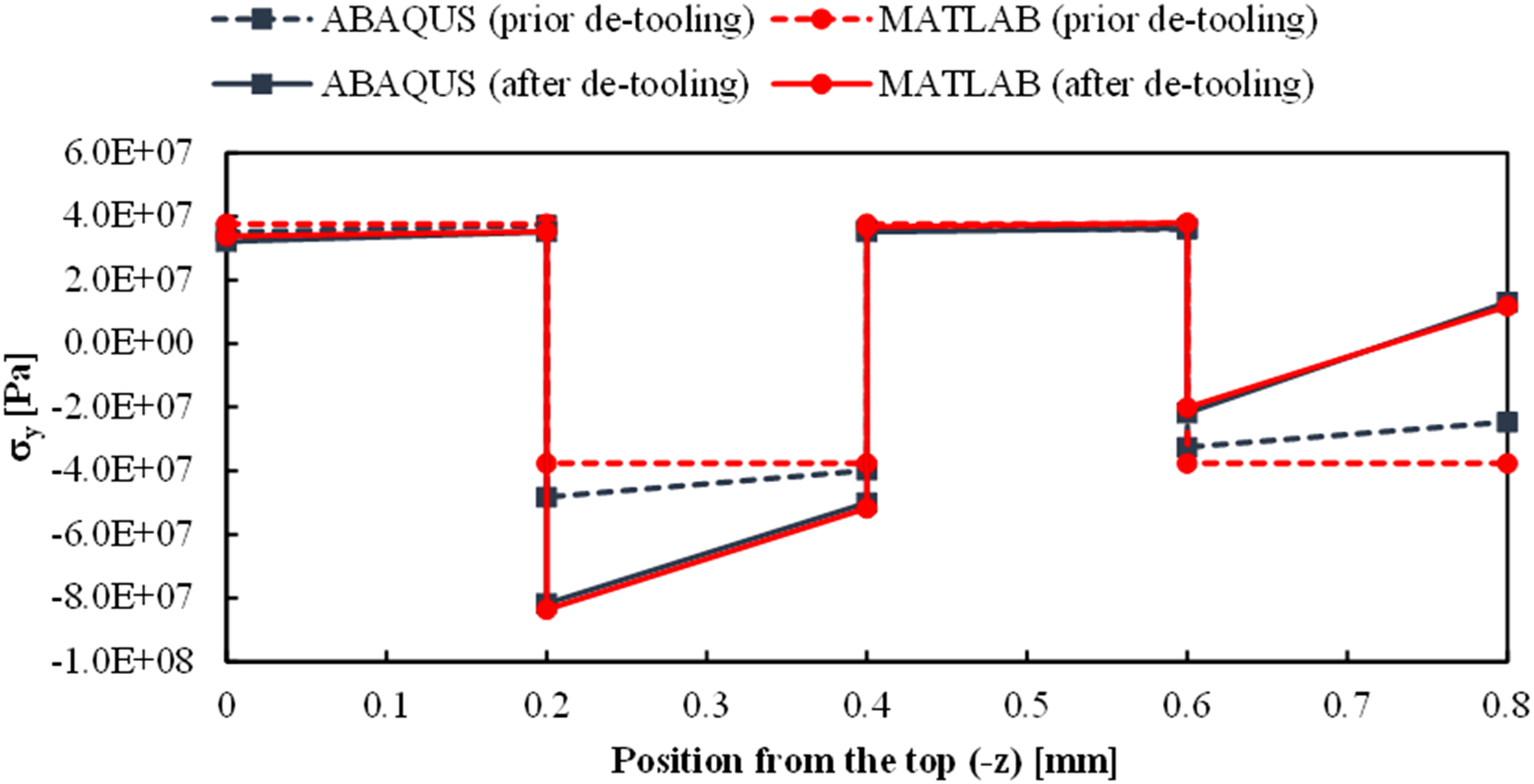
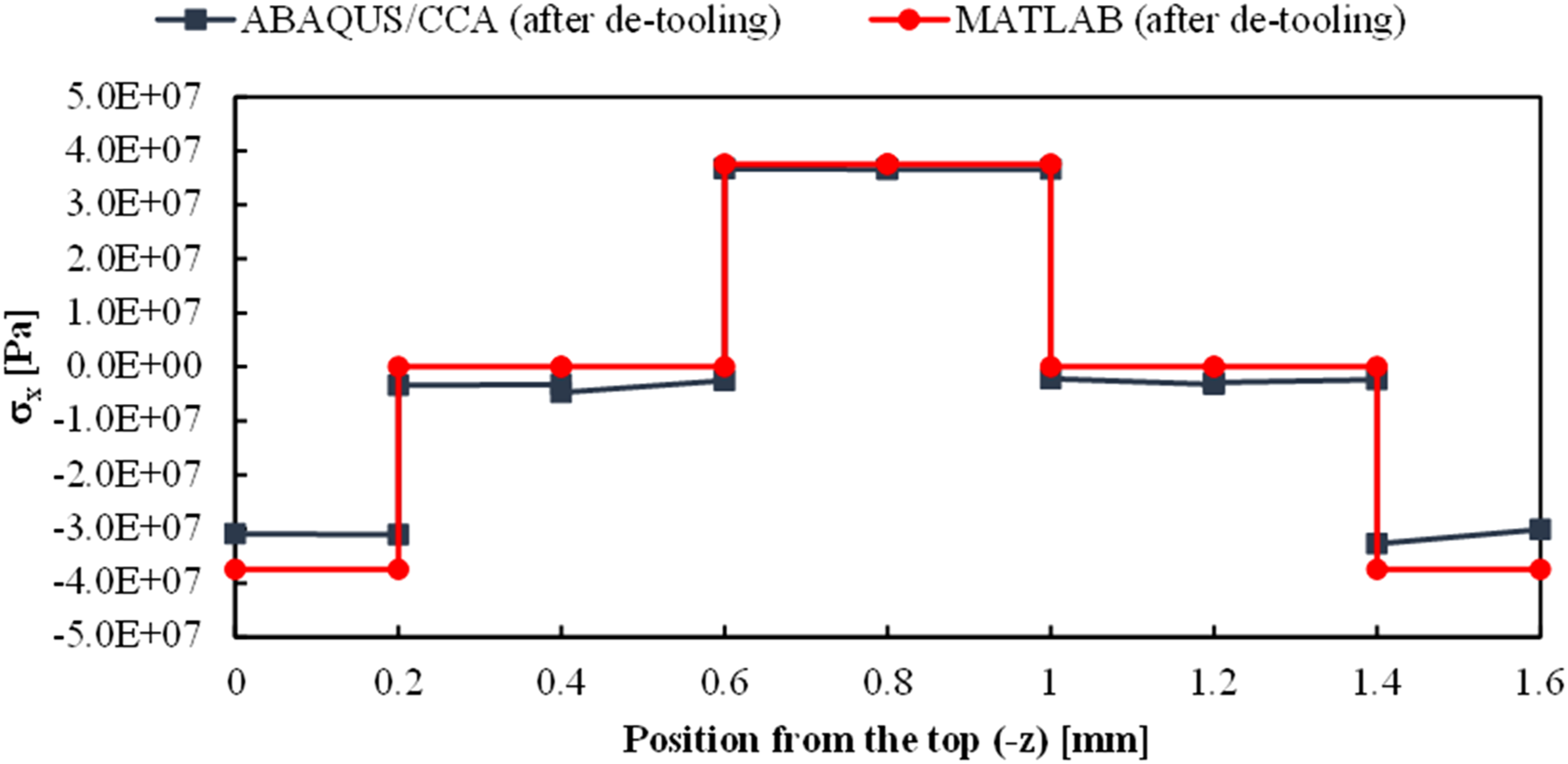
The stress state before and after de-tooling has been compared between the solution from the Matlab tool and Abaqus/CCA (mid position of finite element model) results as presented in Figures 4 and 5 respectively. Very good agreement on the stress state was found particularly after virtually removing the tool. With increasing laminate thickness, the stress state from CLT results increasingly deviates from FEA results as strain incompatibilities between plies are more and more reacted in through-thickness shear deformation rather than leading to in-plane ply stresses during cure stages when the resin modulus is low. Exemplarily a comparison of the stress in x-direction through thickness for the 8-ply laminate is shown in Figure 6. The CLT-based Matlab code still represents the in-plane stresses reasonably accurate, but clearly stress levels particularly in the top and bottom (0°) ply are overestimated. In most of the configurations tested for validation purposes with the residual curvature as target quantity, predictions of the Matlab code are conservative. Stress in x-direction through thickness, [/90]2 laminate before and after de-tooling (results from Abaqus/CCA and Matlab tool). Stress in y-direction through thickness, [/90]2 laminate before and after de-tooling (results from Abaqus/CCA and Matlab tool). Stress in x-direction through thickness, [0/-45/45/90]s laminate after de-tooling (results from Abaqus/CCA and Matlab tool).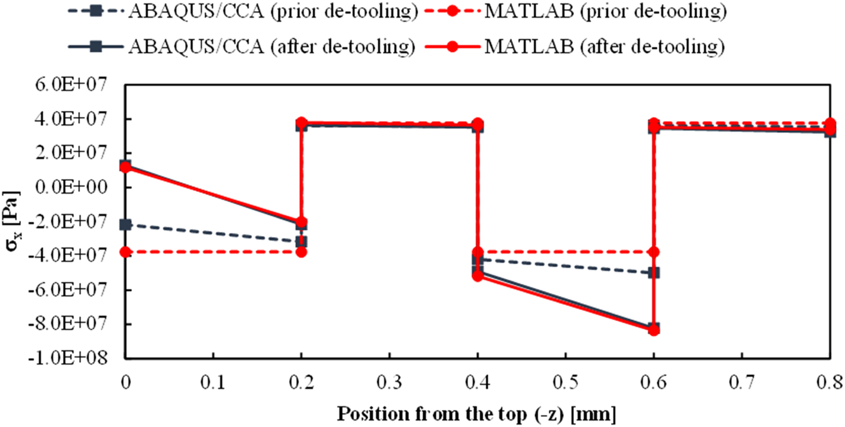
Validation of selected configurations: Abaqus/CCA and matlab tool results.
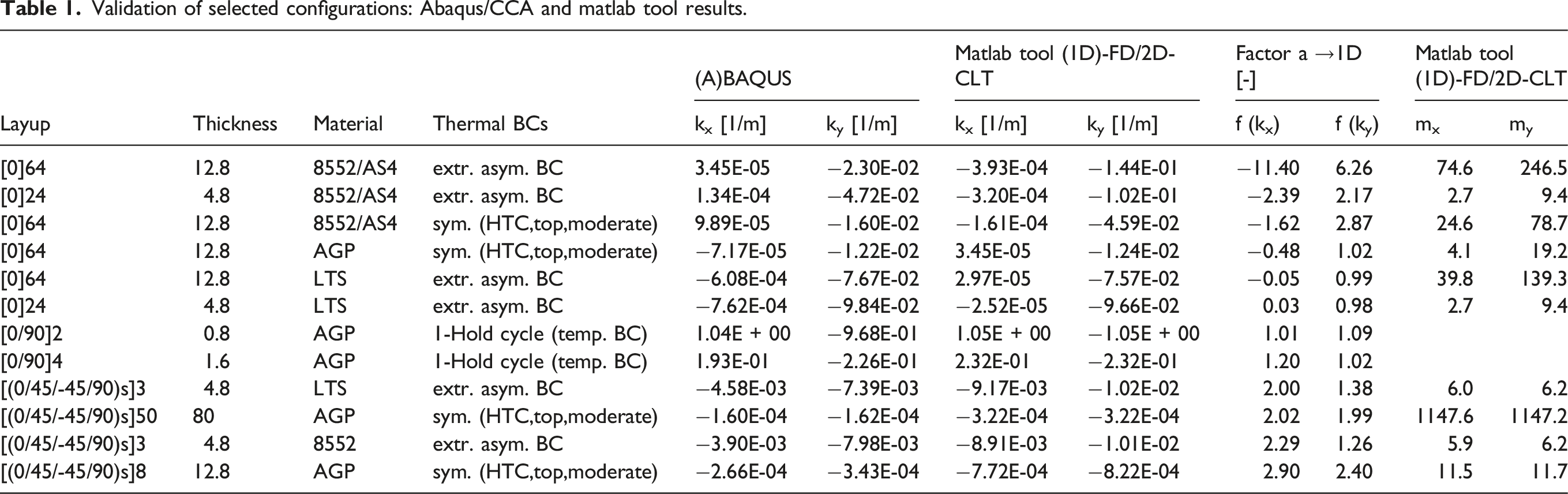
Very good agreement was found for the residual curvature of the 0.8mm and 1.6mm asymmetric laminates, with the Matlab tool predictions slightly overestimating the curvature in comparison with Abaqus/CCA.
For all the unidirectional (UD) laminates, the Matlab tool predicts the curvature in fiber transverse direction being critical considering rigging moment fluxes. This is plausible, given the high strain gradients in fiber transverse direction predominantly due to cure shrinkage generating a residual stress gradient accordingly. In addition, a concordant compound curvature or only a small anticlastic curvature is present on the Matlab tool results for these laminates. On the Abaqus/CCA results, the sign for fiber longitudinal curvature is opposite to the one from the Matlab tool on five out of six cases.
The authors believe that the effect of the through-thickness cure shrinkage is the potential root cause: the ply constitutive law used in CLT assumes a plane stress/strain state, i.e. any stress or strain component in the through-thickness direction is neglected. In contrast, the solid composite finite element model picks up the coupling between the through-thickness strains, which are also inhomogeneous due to the DOC gradient, and in-plane stresses. As the unidirectional plies contract in both fiber transverse directions, the Poisson effect in fiber direction is effectively doubled. In other words, in the CLT based Matlab tool, the curvature in fiber longitudinal direction of the unidirectional laminates is the direct effect of the cure shrinkage gradient in fiber direction, while the FEA results are dominated by the combined effect of contraction in both in-plane and through-thickness direction. On the cross-ply and quasi-isotropic (QI) laminates, the contraction of plies in in-plane fiber transverse direction is constrained by adjacent plies, which is considered dominant, as the sign and magnitude of curvature readings are consistent. On all quasi-isotropic laminates, the Matlab tool consistently overestimates residual curvature and consequently the rigging moments by a factor between approximately 1.3 and 2.9.
For all setups investigated, the rigging moment in fiber transverse direction still sets the upper limit but for the two low temperature system (LTS) laminates when fluxes are scaled to Abaqus results via curvature readings. Consequently, the LTS system has not been considered in section “implications on thickness limit estimates” below.
Parametric study on cure gradient induced warpage
Utilizing the simple tool as presented in the preceding section, manufacturing setups deemed relevant were parametrized and the effects of single factors of influence were analyzed based on a design of experiments (DoE). A full factorial DoE was considered appropriate to gain the full resolution of all interaction effects and unbiased information on the effect of single factors of influence.
Representation of manufacturing setups investigated
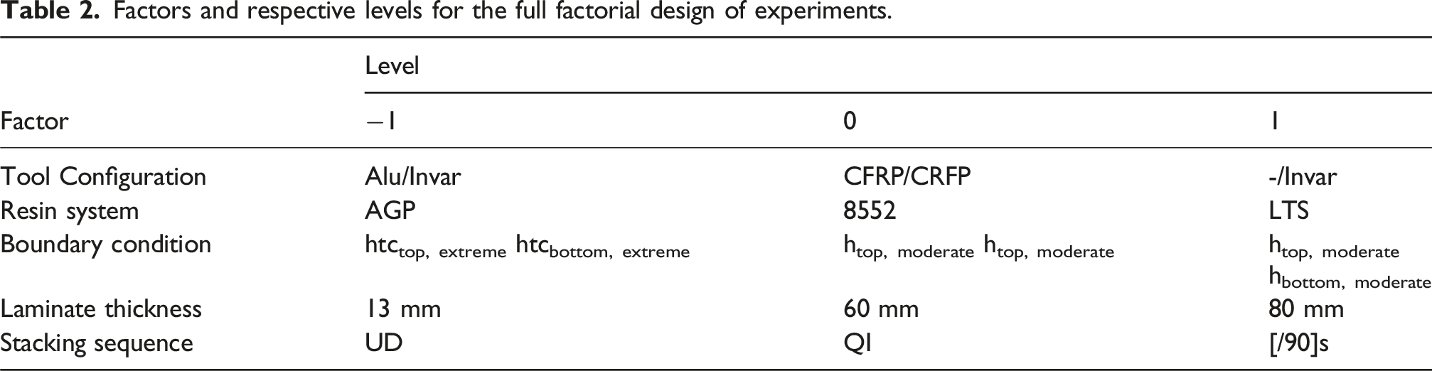
The goal of this study is to evaluate the effect of cure gradient induced warpage covering the major fraction of all processing boundary conditions expected on aerospace manufacturing setups. With this background, a full factorial DoE has been set up, covering the following factors. (1) Tool configuration, (2) Thermal boundary conditions, (3) Epoxy resin system, (4) Laminate thickness, (5) Stacking sequence.
A symmetric DoE requires the same number of levels for each factor, which has been chosen at three.
Typical materials used are Invar, Steel, Aluminum and CFRP. To gain three representative configurations, the setups have been defined as schematically shown in Figure 7. For structural aerospace configurations currently still most frequently used is presumably the single sided Invar tooling setup, with the other two configurations presenting manufacturing alternatives. Material properties used for the parametric study are listed in Appendix A. Tooling configurations addressed in parametric study.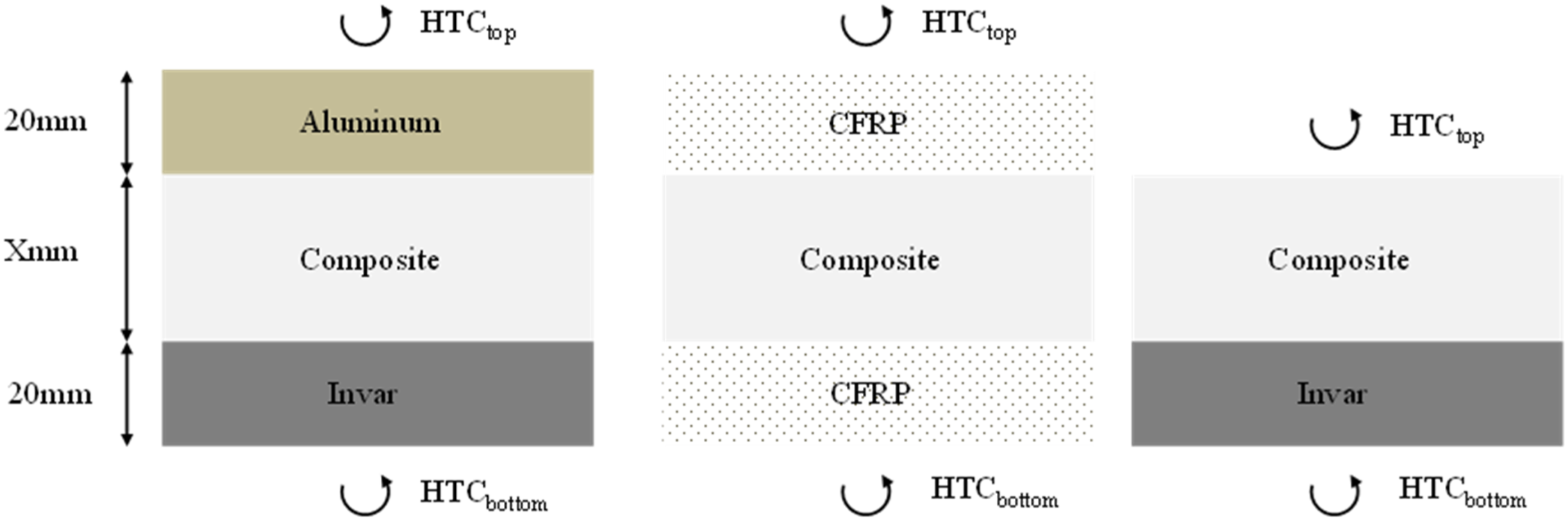
Thermal boundary conditions have been set to represent expected extreme cases for heat transfer properties during typical autoclave (A/C) processing: the upper bound presents a set of extremely asymmetric HTCs characterized by the purely pressure dependent functions used by Johnston
13
:

An intermediate level of asymmetry is introduced adapted from experimental data representing a moderately asymmetric inflow on the tool in a large autoclave.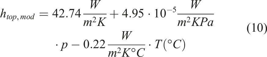
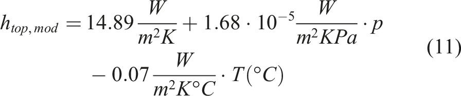
The third level is represented by a symmetric HTC configuration using the moderately high top side HTC (equation (11)).
Three resin systems have been utilized to cover a representative range of reactivity: one system from literature, namely Hexcel AS4/8552 as characterized by Johnston, an aerospace graded prepreg (AGP) material and a low temperature (curing) system (LTS). The latter is a structural epoxy adhesive used in the wind energy industry which is typically cured with heating mats under “vacuum bag only” conditions. Within this study, the LTS has been used in conjunction with the AS4 fiber (FVF = 0.55) to ensure comparability with the remainder of the materials. Each material system is associated with its own standard cure cycle shown in Figure 8, which has been applied for all configurations of the respective matrix system. Standard cure cycles used for the three resin systems addressed in parametric study.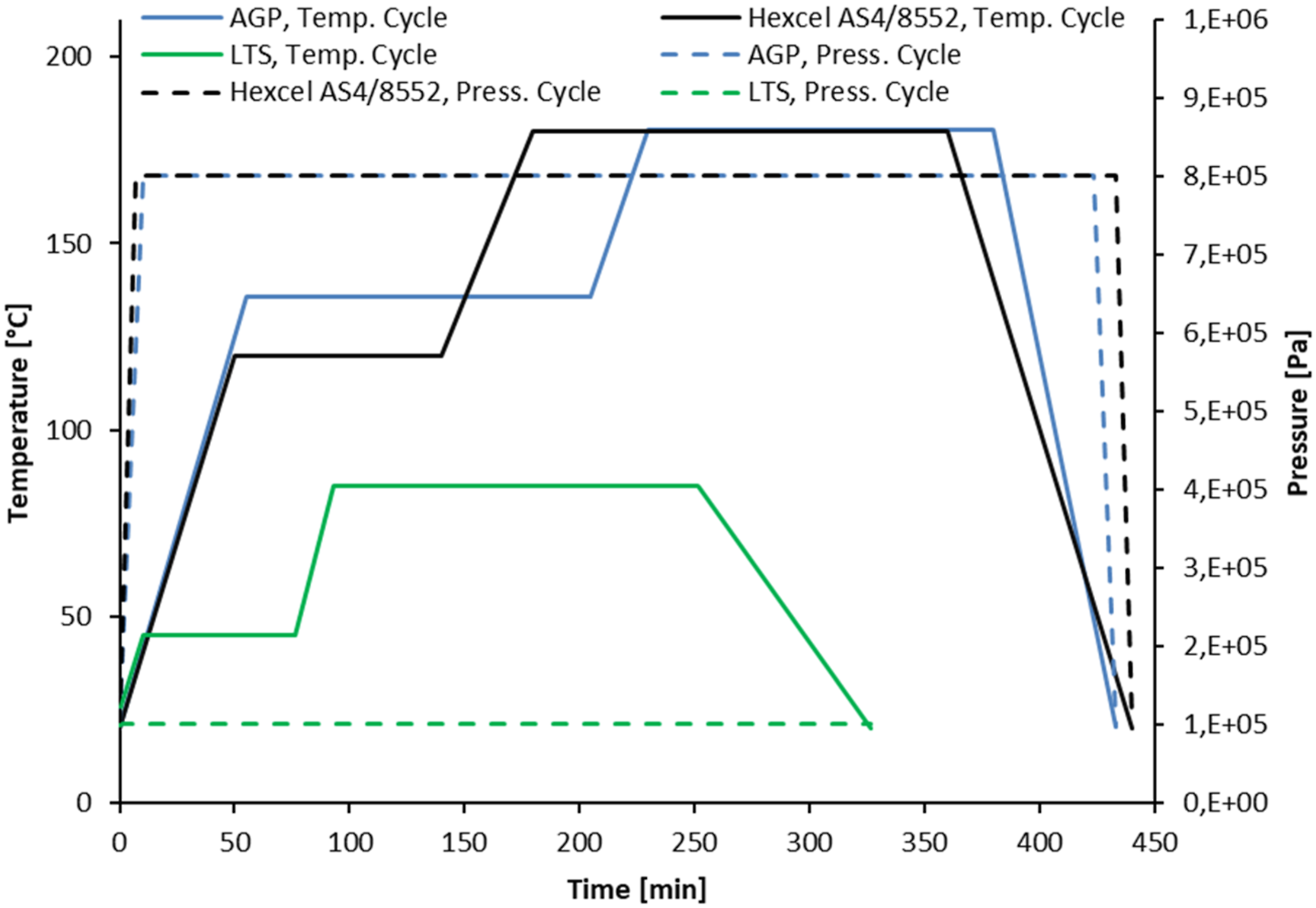
Within the DoE setup and analysis, three thickness levels have been investigated. The lower limit has been set to 12.8 mm inferred from the literature.2,3 The maximum thickness of monolithic CFRP laminates manufactured in RTM known to the authors has a thickness of approximately 80 mm. A nonlinear response of the setup in terms of temperature gradients and deformations is expected and therefore an intermediate level has been set to a thickness of 60 mm. However, all configurations have been analyzed in addition for a laminate thickness of 5 mm and results gained are particularly important for the relevance discussion.
Factors and respective levels for the full factorial design of experiments.
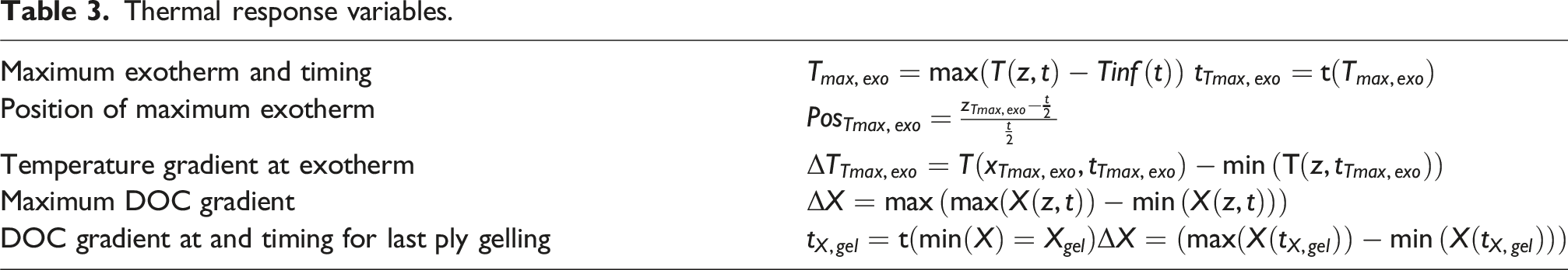
Thermal response variables.
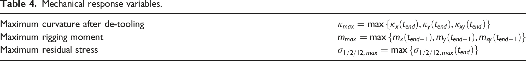
Mechanical response variables.
Results of designed experiments
All data in terms of response variable values and associated factor levels have been used as input for the commercial software package MODDE 18 to conduct the analysis of the DoE. Only results considered most important for the relevance evaluation are presented here. The remainder of main and interaction effects addressed in this study are illustrated in the Appendix.
Variable importance plots
The importance of each factor of influence in terms of main effects and interactions is quantified in MODDE as a weighted correlation quantity based on a regression model. 18 A value of one for the variable importance indicates an average effect.
Analysis of the importance of factors of influence on thermal response variables has been carried out on a subset of the data removing the stacking sequence, for the temperature distribution is independent of this parameter. Figure 9 shows the variable importance (VI) for the thermal response variables. Laminate thickness and the choice of the resin system clearly dominate the coefficients of the regression model for the thermal response variables, indicated with a relative importance of approximately two. Effects of the boundary conditions and the interaction between laminate thickness and resin system already show a much lower than average importance (VI approximately 0.5). Importance of thermal response variables.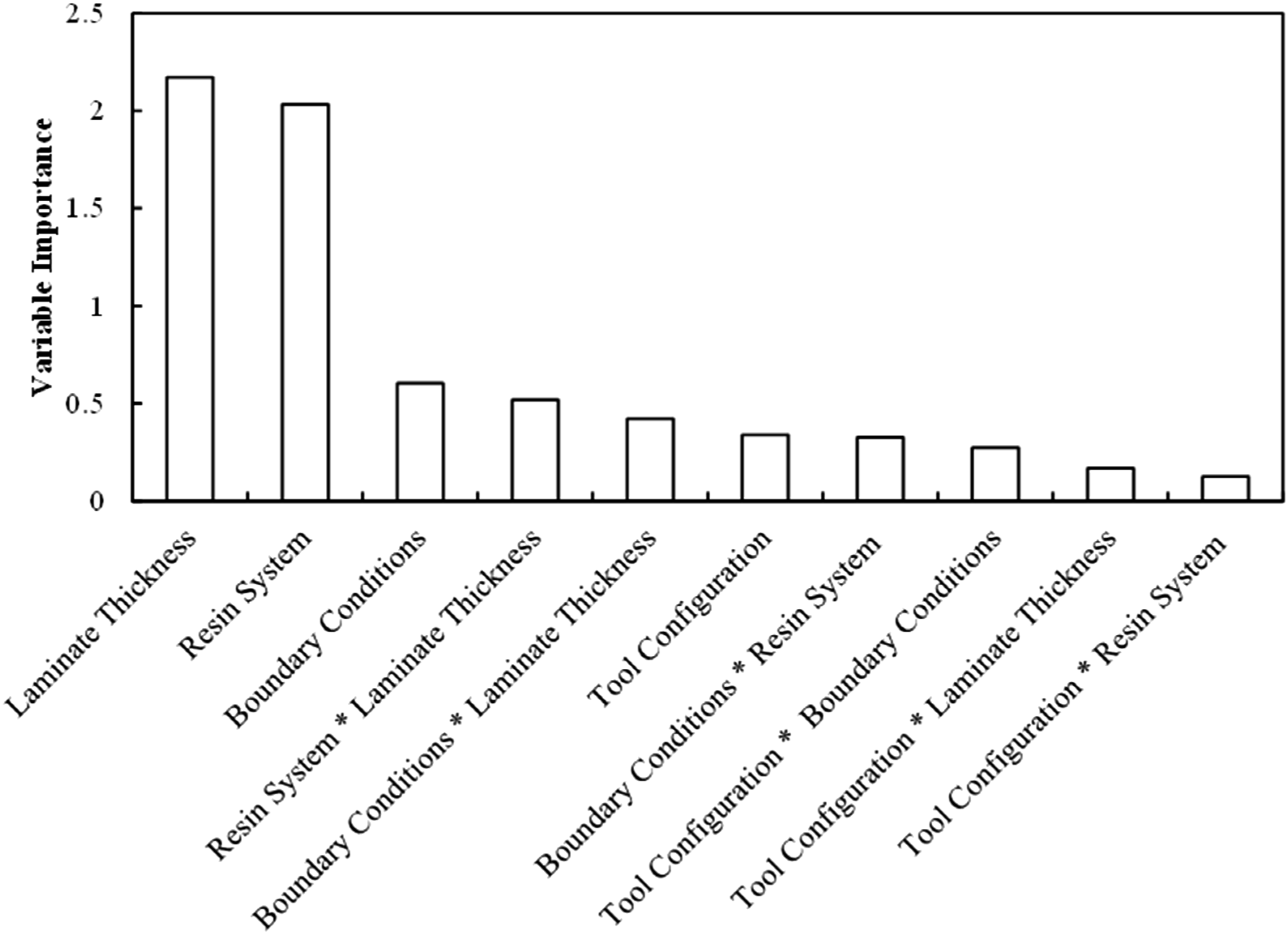
The regression model for the mechanical response variables is driven by the coefficients associated with the main effects of laminate thickness and stacking sequence as well as their interaction, cf. Figure 10. All other factors have significantly smaller importance than the average (VI ≤0.7). Importance of mechanical response variables.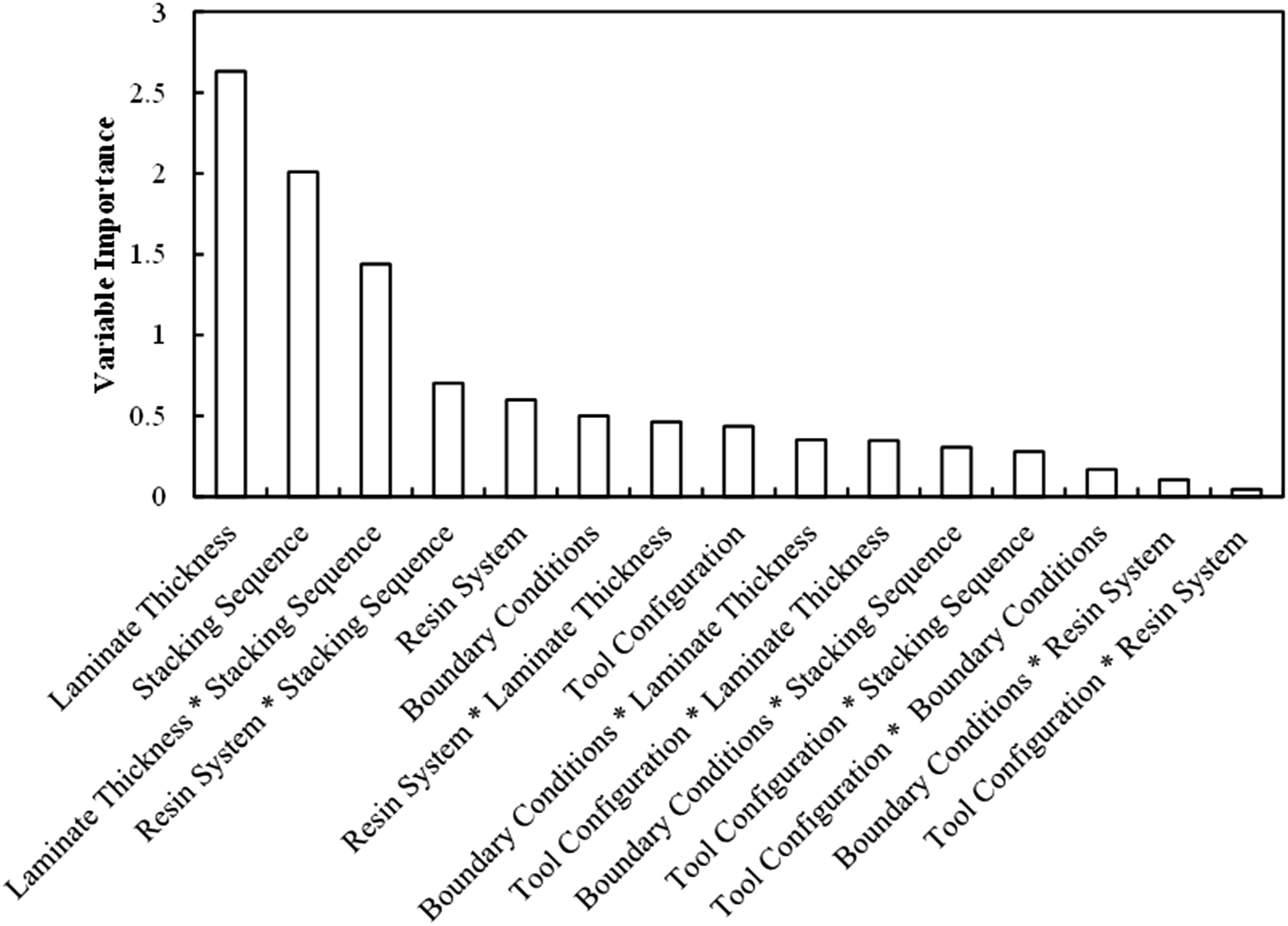
Effects on thermal response variables
Magnitude of the exotherm (maximum temperature overshoot) occurring on the virtual processes and its position through-thickness provide insight into the asymmetry in temperature distribution and its criticality, Figure 11. Apparently, the laminate thickness drives the maximum difference between peak laminate A/C air and laminate temperature. Exotherm measures - main effects DoE.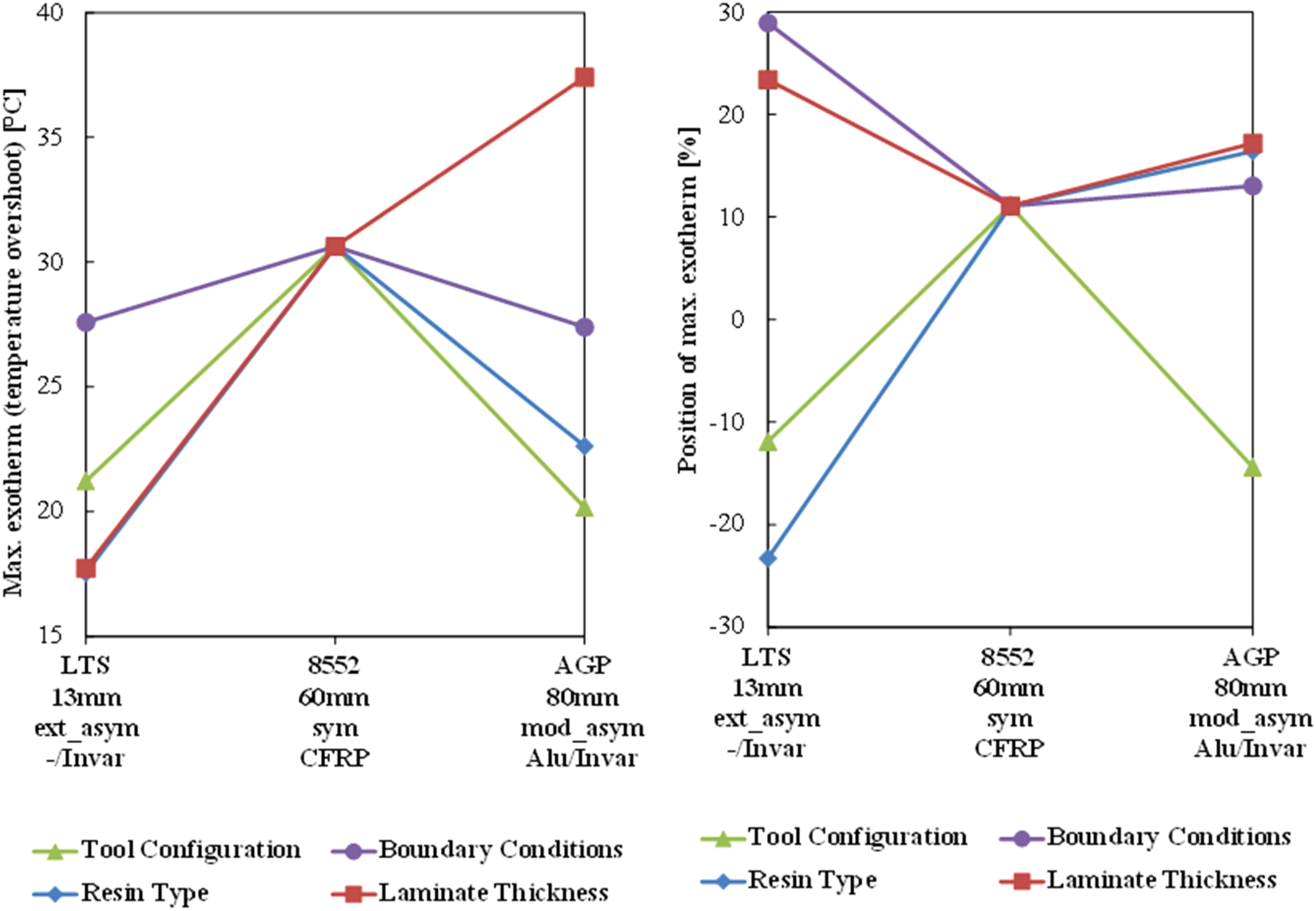
The tool configuration has one of the most important effects on the exotherm: for the symmetric CFRP tooling the peak temperature overshoot is approximately 10 °C higher compared to the metallic tooling configurations. This is to be expected given the low thermal conductivity of the CFRP tool and the comparably low heat flow into the tooling, acting as a heat sink as the exotherm occurs. Exactly this characteristic generates an additional, less expected effect: the temperature gradient through-thickness during processing is lowest for the CFRP tooling on investigated configurations, see Figure 12. This translates into an average DOC gradient of approximately 0.05 when the laminate has gelled compared to 0.15 to 0.2 for the other two tooling configurations. As a result, the residual curvature after processing is smaller as will be shown in the subsequent section. Temperature and DOC gradient measures - main effects DoE.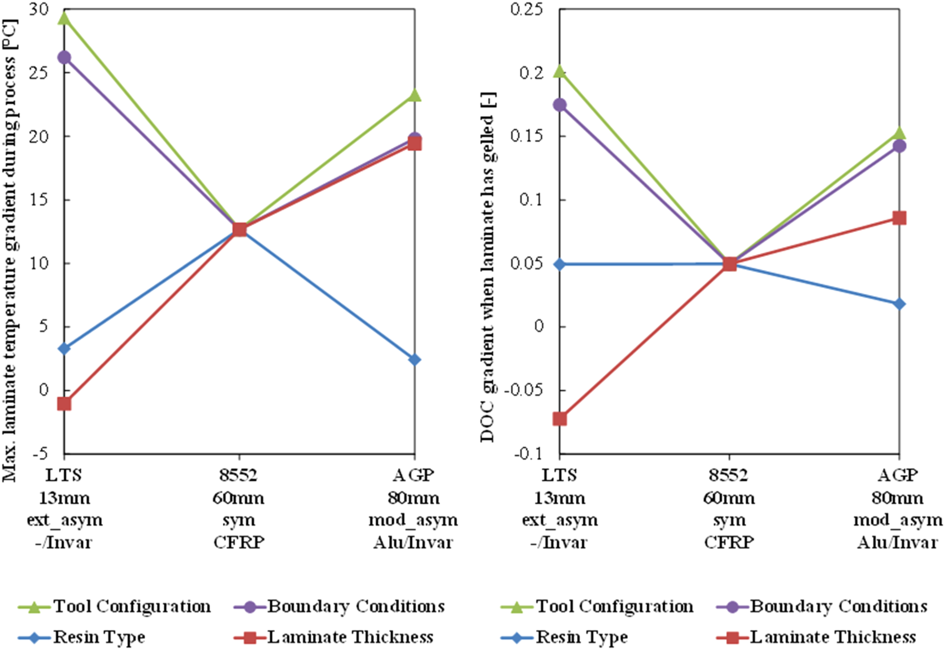
Both the magnitude and the position of the exotherm are strongly dependent on the resin system, cf. Figure 11. For standard processing conditions applied in this study, the Hexcel 8552 resin system as characterized by Johnston 13 generates the highest exotherm and a larger temperature gradient during processing compared to the other two resin systems investigated. Key in understanding this behavior is the cure characteristic discussed in the following.
The thermal boundary conditions and particularly the degree of asymmetry dominate both the maximum through-thickness temperature and DOC gradient at gelation to a similar extent as the tool configuration, cf. Figure 12. They also have an important effect on the position of the exotherm, as plausible given the degree of asymmetry in HTCs translating into a respective temperature distribution prior to the exotherm. Once the major fraction of cure reaction occurs in the vicinity of the peak cure rate, the thermal mass of the tooling becomes the most important factor driving the exotherm and only a small influence of the thermal boundary conditions is present, see Figure 11, left side.
Effects on mechanical response variables
Two groups of factors of influence dominate the system response in terms of maximum curvature after de-tooling: material and stacking sequence related factors as well as tooling and thermal boundary conditions configurations, see left side of Figure 13. Curvature and rigging moment measures - main effects DoE.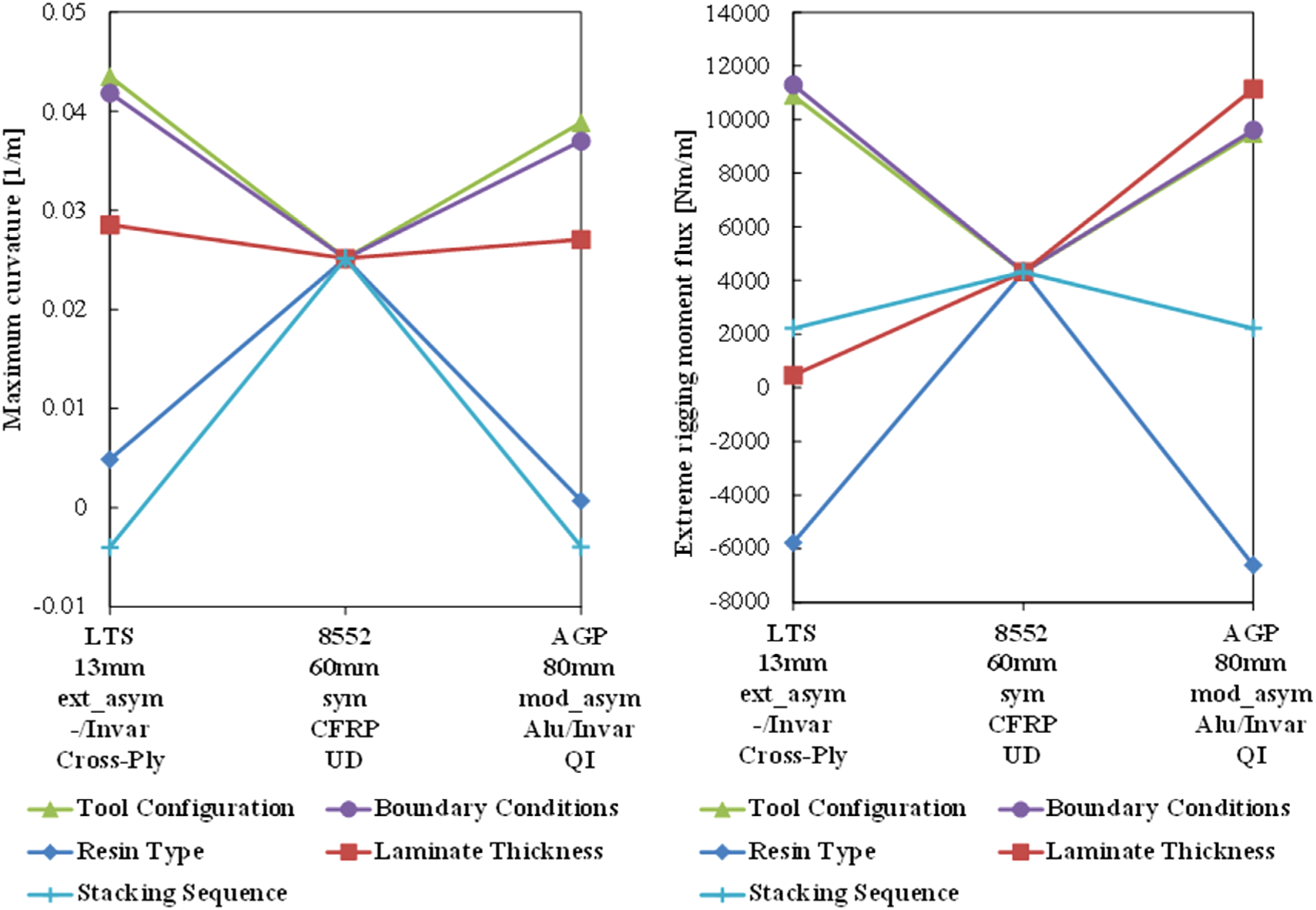
The choice of the material system indicates a much-increased residual curvature for the Hexcel 8552 resin system over LTS and AGP. A similar trend is noticeable for the stacking sequence: the unidirectional laminate generates on average by a factor of five increased residual curvature with an opposite sign compared to cross-ply and QI laminates.
Tool configuration and thermal boundary conditions also show a very similar trend with the symmetric HTC and tooling material configuration resulting in approximately 30% reduction of average residual curvature compared to the other two configurations respectively.
These trends largely convert into the effect on residual moment fluxes required to flatten the cured laminate, cf. right side of Figure 13. Contrary to the curvature, rigging moments dramatically increase with increasing laminate thickness, which is evident given the increase in moment of inertia with the thickness cubed.
Most interestingly, the choice of Hexcel 8552 resin system involves the highest curvatures and rigging moments among the three material systems investigated and the thickness levels tested. There is no obvious reason and therefore further investigations into the interactions of simulated properties during processing are promoted. Contrary to the AGP and the LTS system, the CTE in glassy and rubbery state is the same for the Hexcel 8552 system according to the characterization from Johnston. Compressive stresses “stored” during heat up of the material after gelation can compensate a significant fraction of residual stress and warpage arising during cool down, reported for instance by Spröwitz et al. 19 as the factor between CTE in gelled and glassy state amounts approximately 2-3 for typical epoxy resin systems. 20 Relevant for the difference in CTE being effective is the timing when the laminate is fully gelled, which has been probed for all configurations utilizing the AGP and LTS material. It was found that gelation of the whole laminate is accomplished for both relevant material systems on all configurations investigated within the final hold phase (at target cure temperature level), which starts after 13,800s and 5600s for the AGP and the LTS system respectively.
As the balance between expansional strains during heat up and thermal contraction during cool down has been ruled out to explain considerably higher residual deformations for the Hexcel 8552 resin system, the interaction between cure progress and modulus development was studied. Figure 14 shows cure rate and modulus rise after gelation for an isothermal cure at the respective designated cure temperature, i.e. 180°C for Hexcel 8552 and the AGP system and 85°C for the LTS. For the AGP and the LTS system, the modulus starts to significantly develop around 85-90% DOC, where the cure rate is as low as 2*10−5 [1/s] to 5*10−5 [1/s]. By contrast, the cure rate for the Hexcel 8552 resin systems is still at a level of about 1/3 of the maximum cure rate and amounts approximately 1.6*10-4 [1/s] when the modulus development sets in. According to the characterization from Johnston, modulus development is accomplished well before glass transition takes place, i.e. when the model glass transition temperature is still below the ambient temperature. The outcome of this is, that cure gradient induced shrinkage differences through-thickness (as the only relevant strain contribution here, see above), generate an appreciable through-thickness stress gradient as the modulus is already advanced and translate into elevated curvature and rigging moments. On the AGP and the LTS system, the major fraction of cure gradients occur in the gelled state and the resulting stress gradients are comparably moderate, even though the absolute DOC gradient through thickness may be similar or even slightly higher as for the LTS system, see Figure 12. To illustrate the high spread of cure rates and the effect on the modulus development, model predictions for an isothermal cure at 45°C (first hold phase) are shown for the LTS. In sum, the interplay between cure rate and modulus development as fundamental resin properties drive the criticality with respect to the degree of cure gradient induced warpage contrary to classifying the problem solely with the reactivity. Property development model comparison for isothermal cure: Cure rate and modulus progression.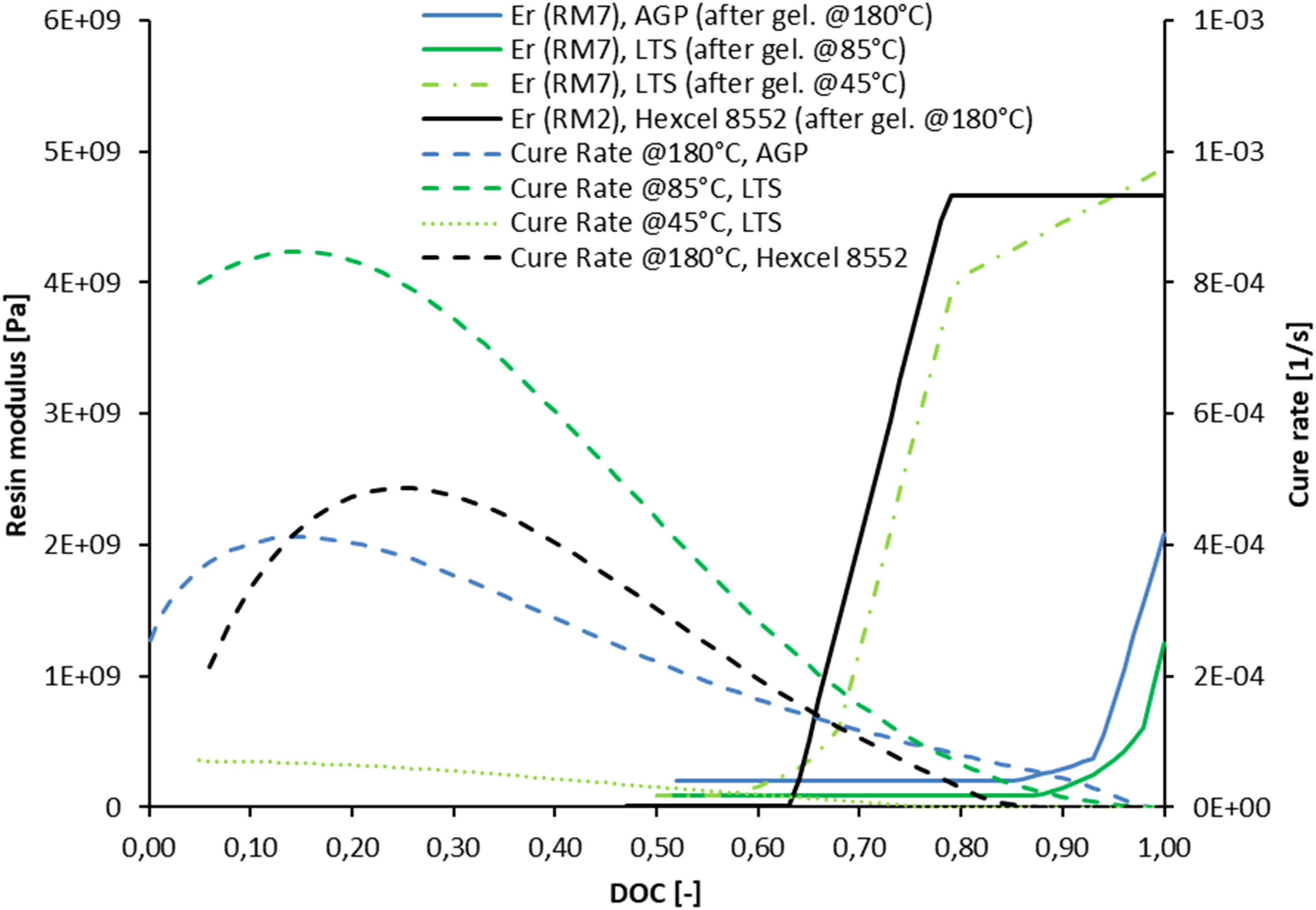
Implications on thickness limit estimates
All curvatures generating a significant bending moment were found to be negative, i.e. result in a convex down bending. This is not surprising given the choice of setups with a generally higher heat flux on top of the laminate. Either because of a higher HTC applied directly on top of the laminate for the single sided tooling or because of the lower conductivity of Invar compared to Aluminum, effectively a delay in temperature history at the bottom of the laminate is generated.
The higher the curvature, obviously the bigger the deviation from a tooling surface “as designed”. However, thin laminates can be bent back easily while the compensation of small displacements on already moderately thick laminates is impossible by hand. Therefore, a heuristic approach is proposed to determine a lower thickness limit for resulting process-related deformations by answering the following question: Can the given deformation be compensated for during manual assembly? Little information is available from literature to quantify an upper limit for manually applicable moment fluxes. Thus, a value has been estimated by testing a conveniently applicable force of the thumb on a hand shut situation, which was found to be approximately 100 N. This fits well with average force values applied in treatments for mobilization
21
and presents a value well below reported cut-offs of hand grip strength reported by Vaisha et al.
22
(> 160 N). The lever arm between thumb and remaining fingers is approximately 150 mm and the moment is distributed on a width of 250 mm, representing two hands within 50 cm. The resulting moment flux is estimated as:
This value has been taken as a threshold for the critical rigging moment flux. By no means this simple estimate for the rigging moment fluxes requires applicability for all mounting situations but is an attempt to quantify mountability.
The higher the degree of asymmetry on the thermal boundary conditions, reflected by the HTCs and the thermal properties of the tooling materials, the higher is the level of rigging moments. Figure 15 shows the progression of maximum calculated rigging moments for unidirectional laminates utilizing the 8552 resin system on -/Invar, which represents the extreme case among all configurations. Also, the estimate for the bound on moment fluxes is plotted. Maximum rigging moment fluxes were found to excellently follow a power function with thickness for all configurations. Maximum rigging moments for 8552 UD laminates, -/Invar tooling configuration.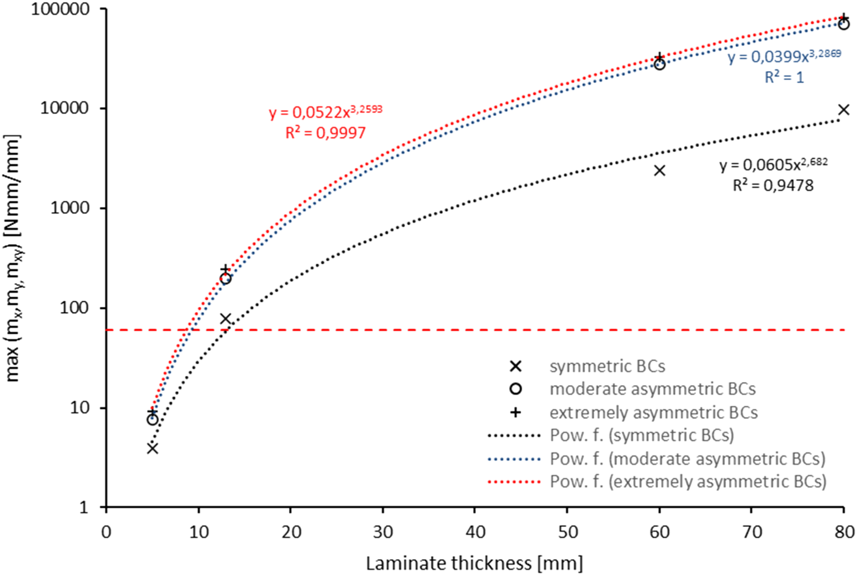
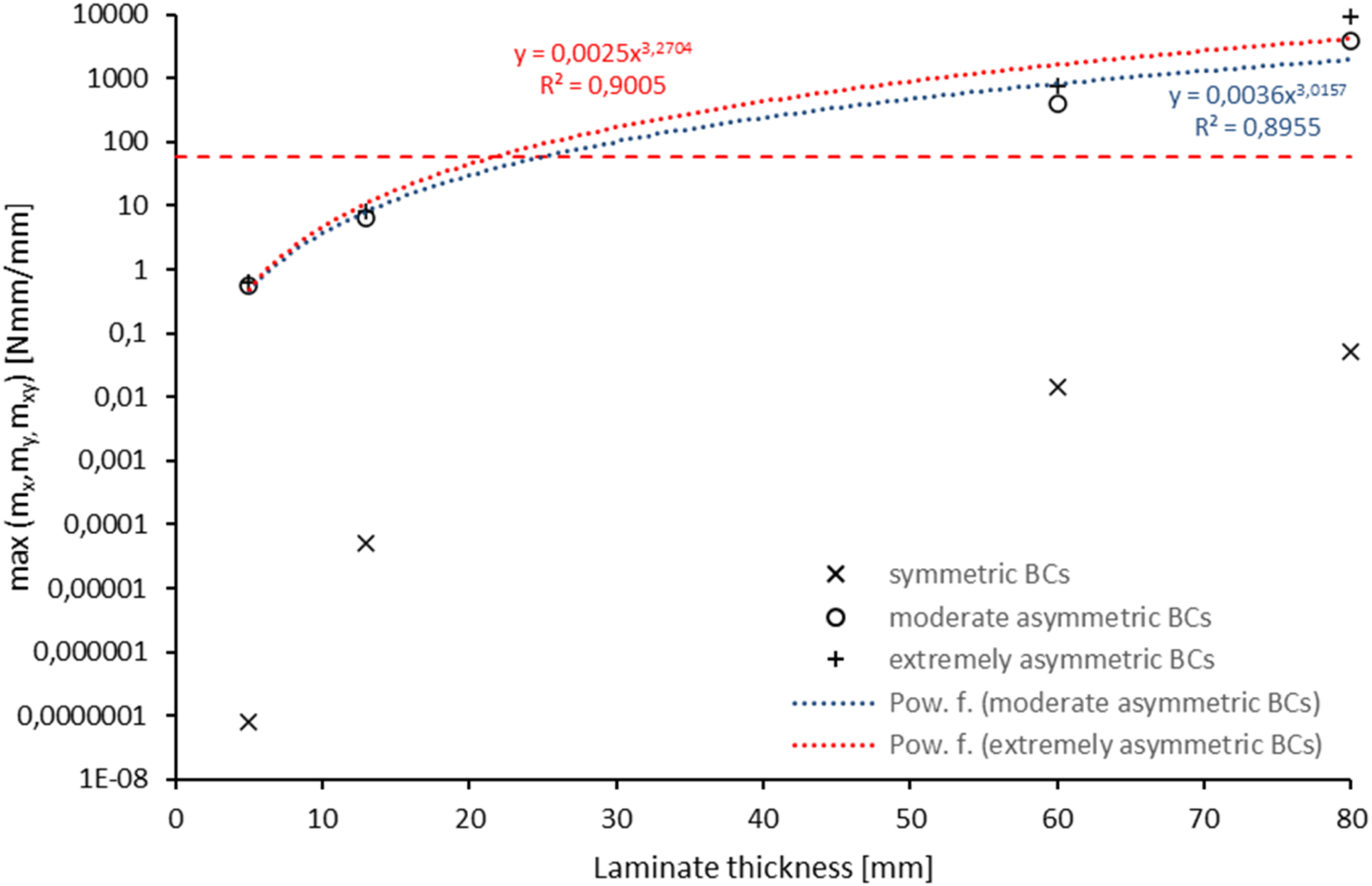
Apparent rigging moments are dominated by the tooling configuration and at least an order of magnitude lower for the two relevant asymmetric HTC boundaries on the symmetric CFRP tooling compared to the asymmetric metallic tooling setups, cf. Figures 16 and 17, respectively. While the threshold rigging moment on metallic tooling configurations is reached at a minimum thickness below 10 mm, on the symmetric CFRP tooling configurations this value is well above 20 mm. Besides smaller deformations, the increased exotherm for the CFRP tooling should be kept in mind. The progression for the fully symmetric CFRP tooling configuration reflects the model numerical accuracy, as a zero rigging moment would be expected for all laminate thicknesses: a maximum moment flux of 0.05 Nmm/mm on one of the extreme cases (80 mm laminate) was calculated. Maximum rigging moments for 8552 UD laminates, Aluminum/Invar tooling configuration. Maximum rigging moments for 8552 UD laminates, CFRP/CFRP tooling configuration.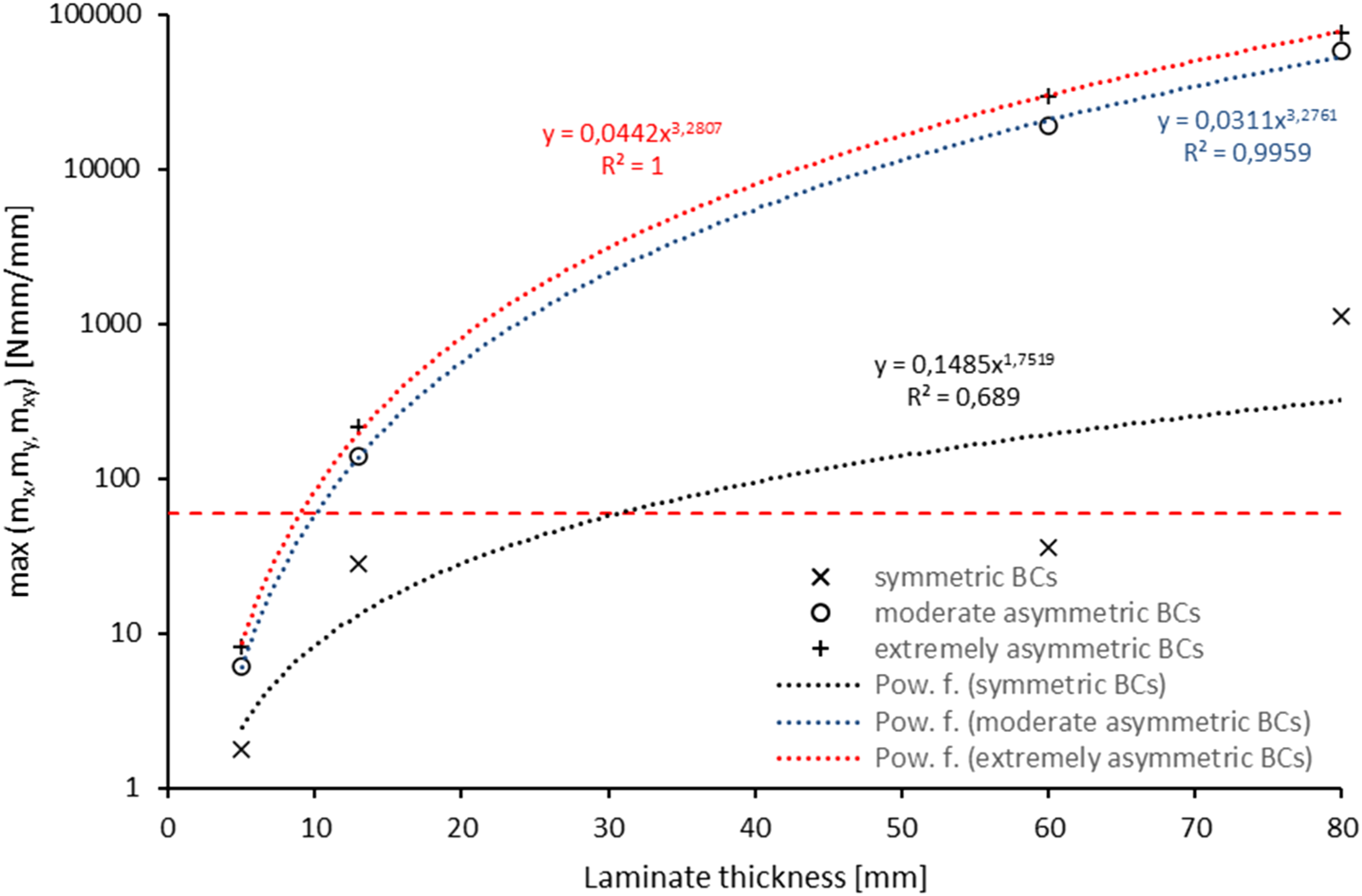
Much more of relevance are cross-ply and quasi-isotropic laminates investigated, which virtually delivered the same results in terms of moment fluxes. As the strain incompatibility between the plies drives the stress build-up and the cross-ply configuration is also quasi-isotropic concerning the in-plane laminate coefficient of thermal expansion, this is plausible.
The level of maximum rigging moments for cross-ply laminates of the AGP system virtually processed on the single sided Invar tooling (cf. Figure 18) is significantly lower compared to the 8552 system. Interpolating the power function trend, a laminate thickness of 18.8 mm is found for the extreme asymmetric case while for the most relevant situation of moderately asymmetric HTCs, this value amounts 20.3 mm. Maximum rigging moments for AGP cross-ply laminates, -/Invar tooling configuration.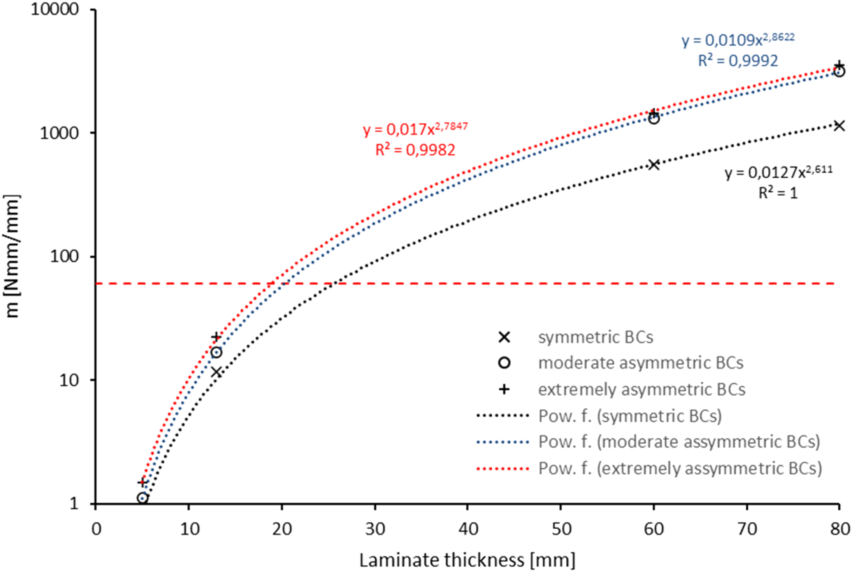
Power functions from regression on data points for all asymmetric HTC boundary conditions were utilized to calculate a minimum thickness where expected rigging moments are still below a given bound, results are presented in Figure 19. Applying a limiting moment flux of 60 Nmm/mm, unidirec-tional laminates up to a thickness of 8.65 mm were found to be within the bound, for QI laminates this limit amounts 9.85 mm. Laminate thickness versus maximum rigging moments, UD and QI laminates.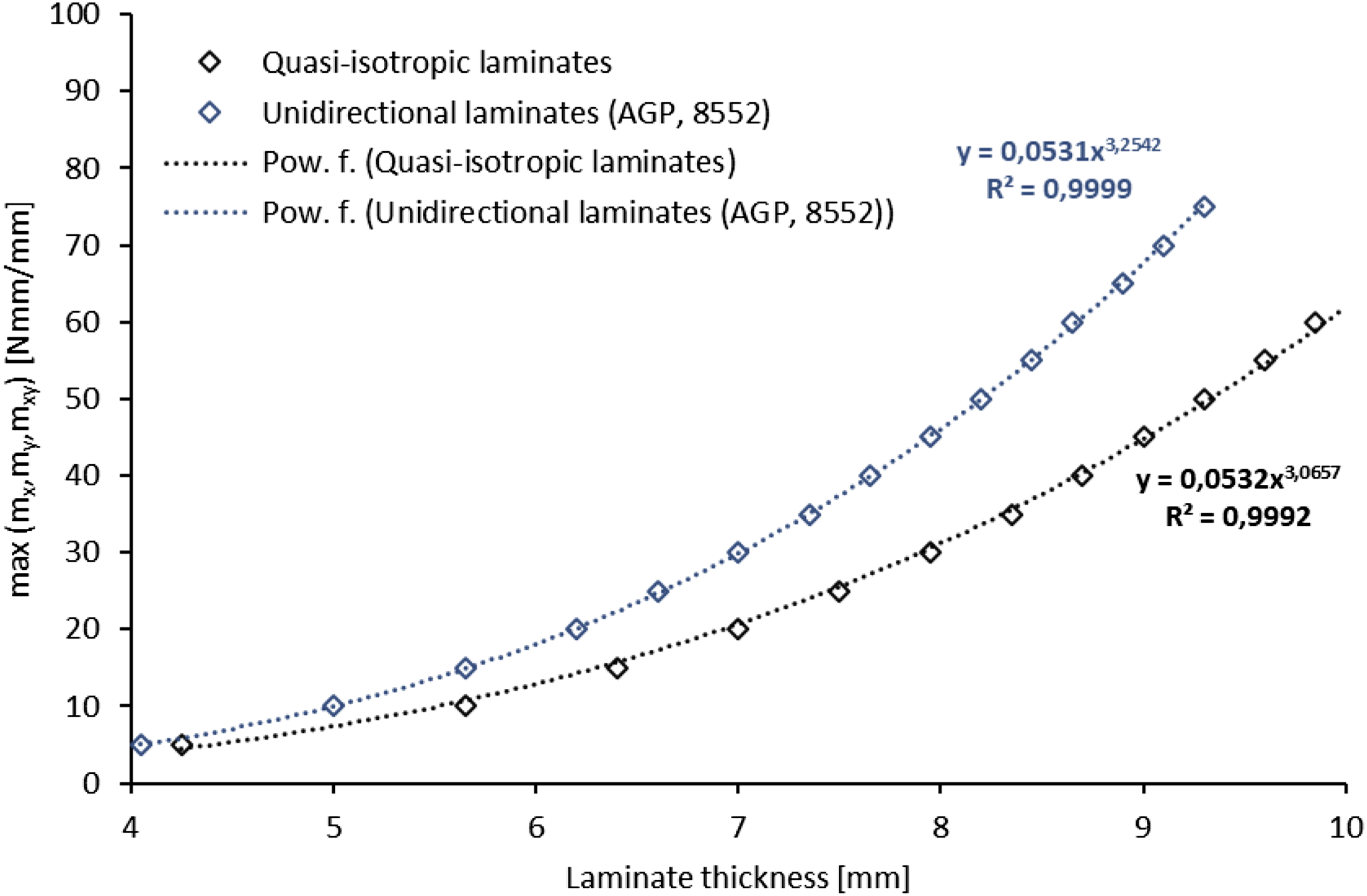
Summary and conclusions
A finite differences scheme to solve the through-thickness heat conduction equation in conjunction with adequate mechanical boundary conditions reflecting the tooling constraint during processing in a CLT formulation has been implemented. Extensive validation of the routine has been carried out: a convergence study on the thermal behavior and comparison between Matlab tool and FEA predictions on mechanical response variables, particularly expected curvatures and rigging moment fluxes.
The main limitation of applying the CLT is naturally that through-thickness effects are neglected, namely both coupling between through-thickness strains with in-plane stresses and out-of-plane shear deformation. As a result, an overestimation of the curvature predictions of up to a factor of approximately 3 in extreme cases has been obtained in comparison with FEA, characterizing the simple process model as being conservative. A full factorial design was applied on virtual manufacturing configurations representing setups across typical applications from aerospace and wind turbine rotor blades. While the thermal response variables were dominated by the laminate thickness and the resin system, the laminate stacking sequence and its interaction with the laminate thickness have shown highest importance in conjunction with the laminate thickness on the mechanical response variables including residual warpage.
In search of a simple measure to evaluate the effect of cure gradient induced warpage as being critical, manually applicable rigging loads have been used to formulate a limit where the laminate could still be bent back into a flat shape. Considering cure gradient induced warpage as a single mechanism for process induced deformations, the lower bound for critical rigging moments in terms of thickness was quantified for cross-ply, quasi-isotropic and unidirectional laminates. Applying this criterion on typical aerospace manufacturing setups, the limit appears to be consistent with the well-known 20 mm rule of thumb. Adding the data of configurations involving a high reactivity low temperature resin system and extremely asymmetric thermal boundary conditions, this limit drops to approximately 8.5 to 10 mm. If additional mechanisms, for instance tool/part shear interaction, are active, combined effects need to be considered accordingly, cf. 23
Supplemental material
Supplemental material - Cure gradient induced warpage: Bounding critical thickness
Supplemental material for Cure gradient induced warpage: Bounding critical thickness by Mathias Hartmann, Christoph Loy in Journal of Composite Materials.
Footnotes
Ethical considerations
This article does not contain any studies with human or animal participants. There are no human participants in this article and informed consent is not required.
Funding
The authors disclosed receipt of the following financial support for the research, authorship, and/or publication of this article: The project was carried out as a side project within the framework of the first author’s doctoral thesis. There is no funding specifically allocated to the work presented.
Declaration of conflicting interests
The authors declared no potential conflicts of interest with respect to the research, authorship, and/or publication of this article.
Data Availability Statement
Data and routines are provided on request.
Supplemental material
Supplemental material for this article is available online.
References
Supplementary Material
Please find the following supplemental material available below.
For Open Access articles published under a Creative Commons License, all supplemental material carries the same license as the article it is associated with.
For non-Open Access articles published, all supplemental material carries a non-exclusive license, and permission requests for re-use of supplemental material or any part of supplemental material shall be sent directly to the copyright owner as specified in the copyright notice associated with the article.