
Abstract
While natural fibres may not match the mechanical properties of synthetics ones, they offer the environmental benefits. Hybridisation is one approach to enhance the mechanical performance for relatively moderate strength applications. In this investigation, the characteristics of sandwich composites with carbon fibre reinforced laminates as the skin structure with core materials of hemp fibre, Nomex honeycomb, and 3D Core infusion foam under quasi-static loading have been investigated and compared with the response of plate using flax fibre reinforcement for the skin laminate and the core materials remains the same. The samples were manufactured by hand layup and autoclave curing for the skin laminate and then glued to the core material. They were conducted using the universal testing machine at the loading rate of 10 mm/min. Two different fibre orientations, [0°/30°/60°/
Introduction
Materials are integral part of our society and daily lives. They play a significant role in defining the performance, durability, and functionality of manufactured products and structures. In recent years, carbon fibre-reinforced polymer composites (CFRPs) have gained significant attraction in some of the industrial application including the aerospace industry. 1 The aircraft manufacturers, like Boeing and Airbus, emphasised the use of CFRPs for secondary aircraft structures that do not compromise flight safety. About 30%–40% of modern airframes are now composed of composites, with this percentage steadily rising owing to ongoing technological advancements in the field. 2 This surge is primarily attributed to the impressive mechanical characteristics of fibre reinforce composites, which include low density, high tensile strength, and high modulus.
The samples used in this investigation were sandwich composite panels consisting of fibre reinforced composite skin of different configurations and different types of core materials. The primary objective in manufacturing sandwich structures was to achieve optimal stiffness and strength while minimising the overall weight, which is attributed to the core structure. These kinds of structures are used by several industries including the civil, marine and aviation industries. Composite sandwich structures are lightweight, strong and termite resistant making them favourable for civil construction. They are also accepted in flooring systems because of the lightweight and strength properties, as with the reduction in weight smaller supporting members can be used. Sandwich composite panels with honeycomb core materials are widely used in the aerospace sector because of the stiffness-to-weight and strength-to-weight efficiencies and hence savings on the fuel consumption.
Research was conducted by Sadeghian et al. 3 on sandwich composite beams manufactured with flax fibres reinforced polymer and glass fibre reinforced laminate as the skin material. Their findings indicated that sandwich composites featuring flax fibre reinforced polymer skin and natural cork core materials showed a comparable structural performance with respect to their counterparts made of glass fibre reinforced polymer skin and synthetic honeycomb core materials. Islam and Aravinthan 4 tested sandwich composite panels made of glass fibre reinforced polymer skins and phenolic core material under point loading and distributed loading separately. The samples were supported at two edges and then on the four edges. They observed that the results were similar in both loading conditions. In addition, Malcon et al. 5 reported about the compression characteristics of composite sandwich structures made of corrugated core with foam inserts and woven glass z-yarn fibres infused with epoxy skin.
Jin et al. 6 tested sandwich structures with new integrated woven corrugated cores under compression, shear and bending loads to study the failure modes and mechanical properties; and observed that because of the anisotropic characteristics of the core the resistance to shear was improved. Also, Zhang et al. 7 created corrugated sandwich composite structures and investigated on how to improve strength and stiffness by controlling the parameters of types of fibres, corrugation angle, core thickness and the bonding between the core the skin. They observed that hybridised glass fibres and carbon fibres (50:50) of the skin showed the same equivalent specific bending strength as that of carbon fibre composites only; also increase in the corrugation angles and thickness of the core enhanced the specific bending strength.
Furthermore, Hou et al. 8 manufactured sandwich panels made of aluminium skin and trapezoidal aluminium cores and tested under crushing load. The core configurations of the samples varied as regular-arranged, stagger-arranged and cross-arranged (0/90). Their results revealed that the cross-arranged (0/90) panels performed better for the peak load and the energy absorbed. Then, Ruan et al. 9 subject sandwich panels made of aluminium foam core and aluminium skin to static loading and concluded from the results obtained that thick face sheet structures resulted in higher load levels and peak load. In another related study Farrokhabadi et al. 10 concluded that multilayer sandwich composite structures improved the strength and energy absorption significantly.
Sayahlatifi et al. 11 tested hybrid composite made of aluminium as the face sheet and the combination of balsa wood with E-glass fabric as the core under four points bending load and found the behaviour suitable to avoid catastrophic failure. While Mahmoudabadi and Sadighi 12 conducted quasi-static punch test on sandwich panels of honeycomb metallic core and aluminium plate face sheet. Some failure modes such as face sheet wrinkling, debonding, tearing, core crushing were noted and concluded that increase in the thickness of the core improves the energy absorbed compared to increase of the skin thickness. Fan et al. 13 in their study on quasi-static compression and three-point-bending tests on the woven textile sandwich material discussed about the failure mechanism of the structure.
Jackson and Shukla 14 reported that high velocity impact on sandwich composite structures has the most effect on the exit face sheet compared to the core and impact face, while damage effect by low energy impact concentrated on the impact face sheet the side of the core attached to it. Chen et al. 15 have developed a numerical model to interpret the damage characteristics of carbon fibre composite sandwich structures with honeycomb core subjected to impact loading and the finding were validated by comparison with the experimental data. In addition, Zhang et al. 16 performed quasi-static loading test on sandwich composite beam made of carbon fibre-reinforced plastic skin and aluminium foam core to examine the failure characteristics and observed face-sheet fracture, indentation and core shear.
Hachemane et al. 17 manufactured sandwich panels made of natural cork materials available in Algeria and jute/epoxy composite skin and tested them for impact loading and indentation to study the damage characteristics. The cork density and impact energy were key parameters influencing the maximum force and damage level. In another related study, Zhao et al. 18 performed static loading test on pyramidal lattice stitched foam sandwich composite and compared the results to that obtained from foam sandwich structure and found significant improvement on the mechanical properties using the lattice stitched foam. In the study conducted by Mazzuca 19 it was revealed that homogeneous polyethylene terephthalate (PET) sandwich panels demonstrate higher ultimate loads compared to their counterparts using polyurethane (PUR) foam, which was attributed to the superior shear strength of PET foam in contrast to PUR foam.
This study is about the characteristics of flat plate sandwich composite structures under quasi-static loading using flax fibre reinforce polymer and carbon fibre reinforced laminates as the skin structure with various forms of core materials (i.e., hemp fibre, honeycomb core, and recycled PET foam). The effect of various skins laminates of various stacking sequence was considered. Strength parameters extracted from the test data were compared to evaluate the effect of the core materials on the characteristics obtained from the composites under the low-speed loading. In addition, the structures with flax as part of the skin material makes them less expensive than synthetic fibres due to their abundance and renewability.
Materials selection
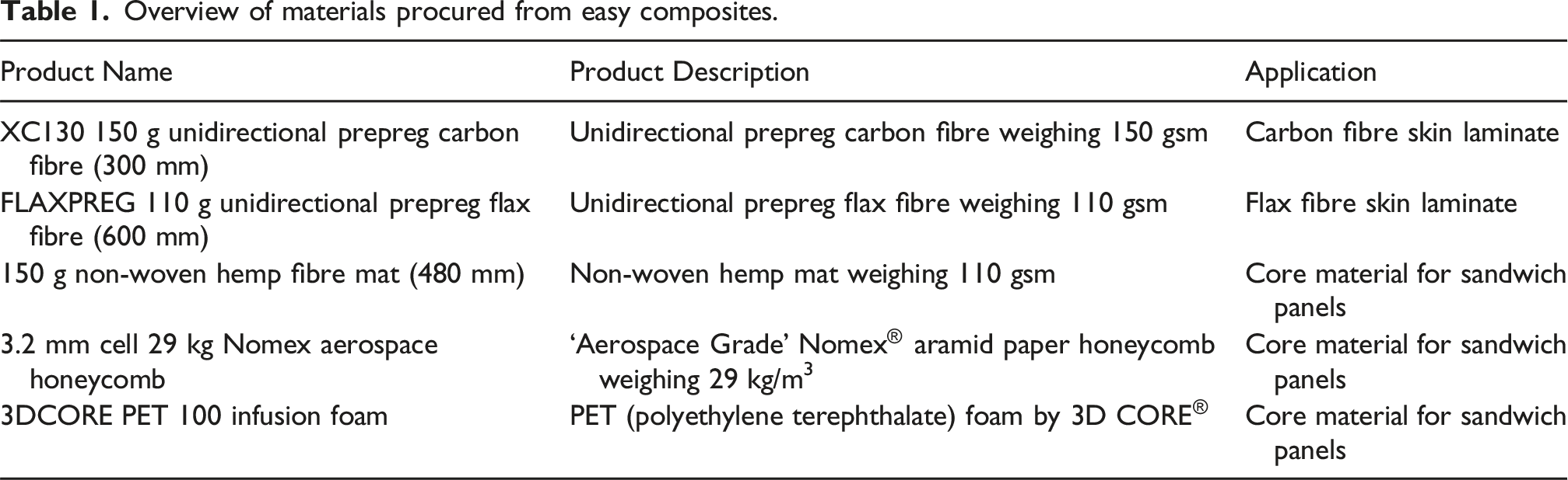
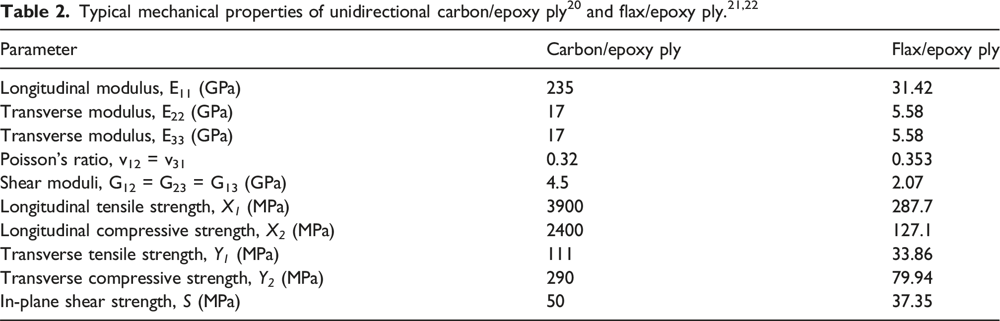
Overview of materials procured from easy composites.
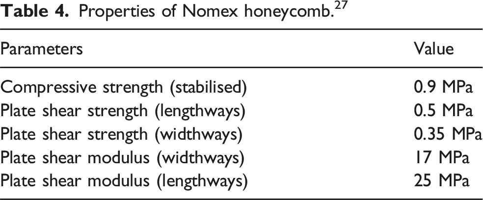
Properties of Nomex honeycomb. 27
Structural design of composite is intended to meet specific requirements. The materials selected for the manufacture of the sandwich panels of various configurations in this investigation are used in the industries. The results about the damage management and characteristics of these engineered structures are to serve as pointers for the user of composites.
Manufacture of panel face sheet laminates and the configurations
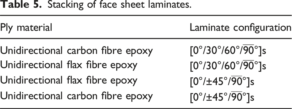
Stacking of face sheet laminates.
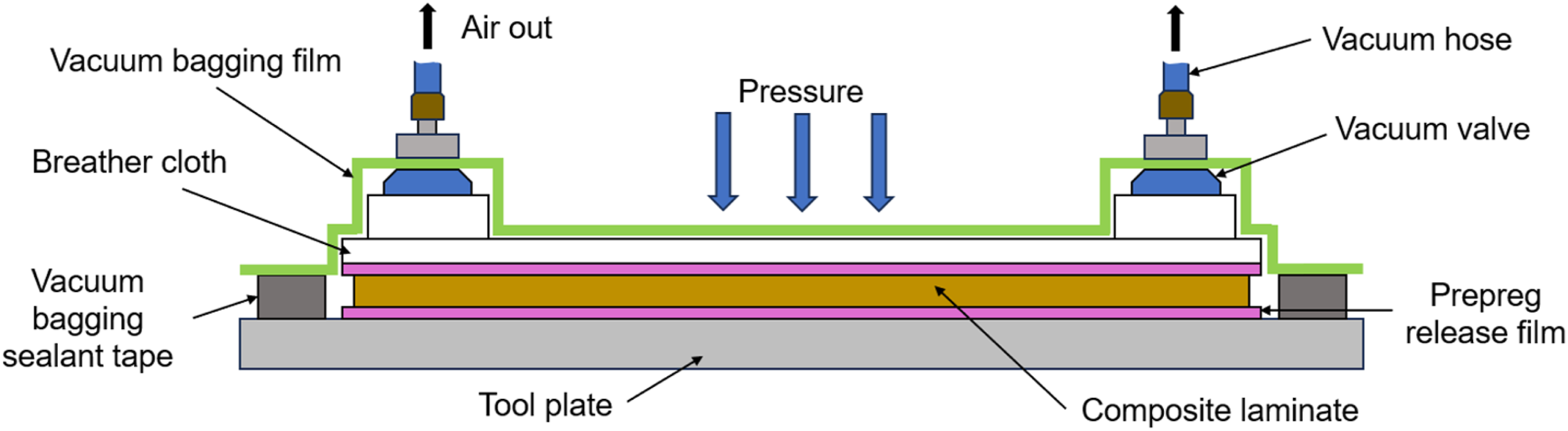
The laminates were cured with the autoclave product of vacuum furnace engineering (VFE) to attain the structural strength before combined with the core material to form the sandwich structure. The process applies the combination of pressure and vacuum on the samples. The vacuum tries to eliminate air in the bagging and entrapped within the plies during the layup, while the pressure helps to suppress vapour within the resin and prevent voids. In Figure 1 is the photograph of the autoclave with the samples bagged and placed on the bed of the autoclave and the bagging of the samples illustrated with schematic diagram of Figure 2. Autoclave loaded with laminate for curing. Cross-sectional illustration of laminate bagged and under pressure in the autoclave.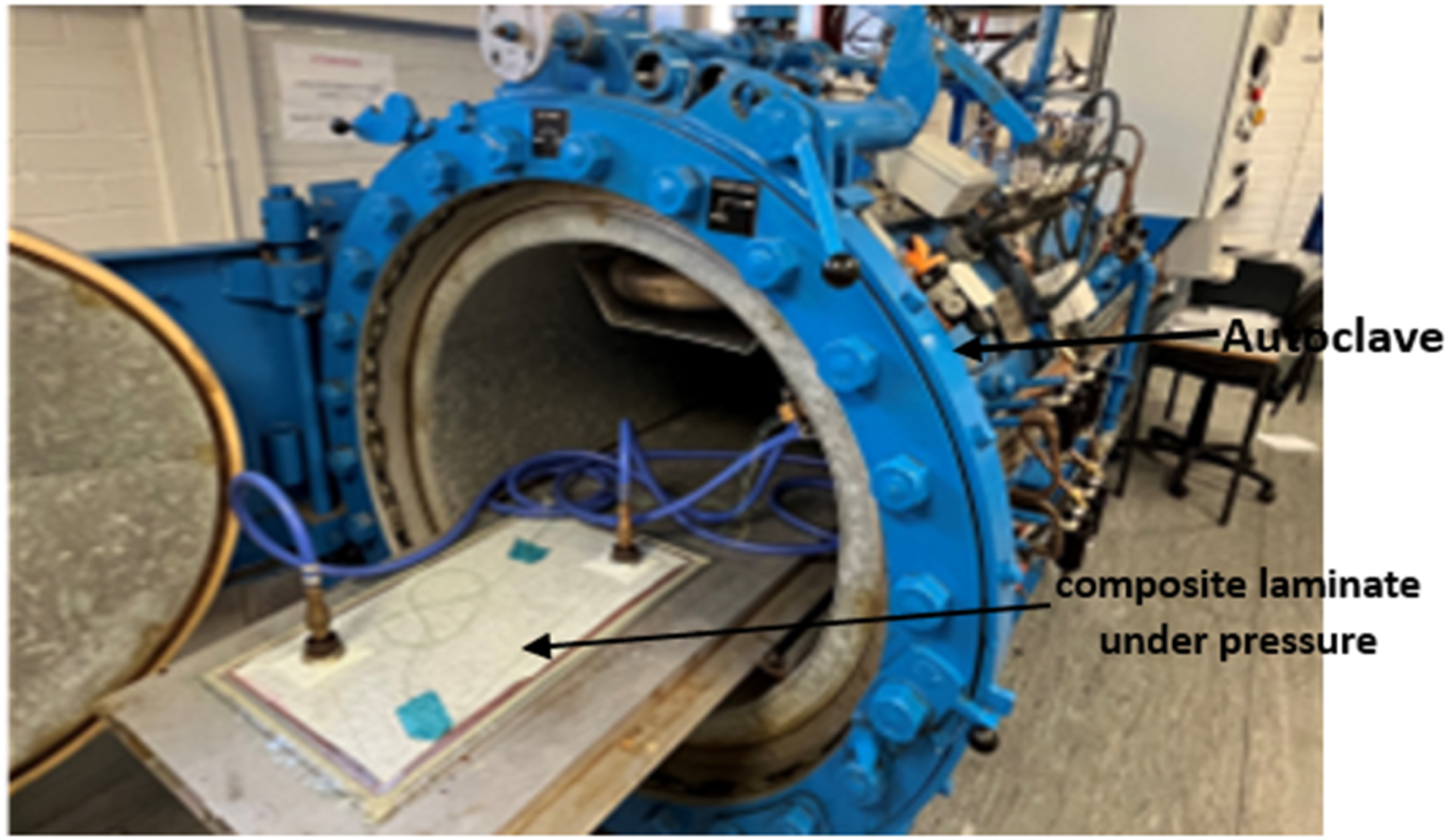
The cycle used to produce laminates is illustrated in Figure 3. It was heated gradually from room temperature to 123°C at the rate of 1.5°C/min and maintained at this temperature for a period of 60 min. After which it was cooled at the rate of 5°C/min to 70°C and 50°C; held at these temperatures for 2 min and then allowed to cool gradually to room temperature. The samples were under a pressure of 4.14 bar during the process. After completion of the curing process in the autoclave, the assembly was carefully taken out of the unit; the sealant and bagging material removed, followed by the breather cloth and release film before taking it out. The removal of subsidiary material and cutting of the samples with a guillotine was carried out with great care to maintain test coupons quality. Laminate cure cycle.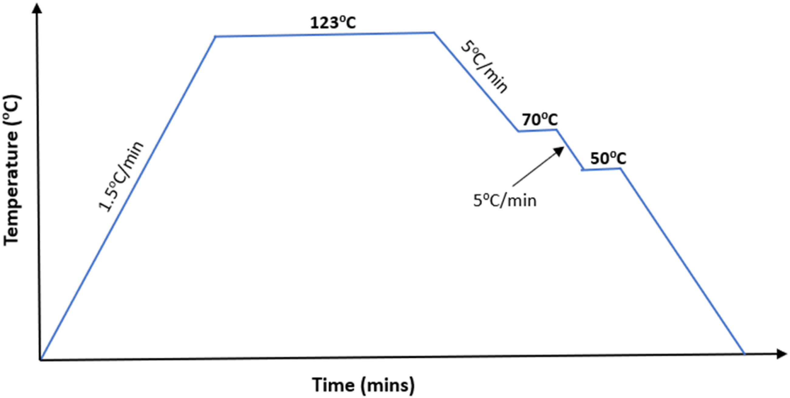
Fabrication of the sandwich panels
The sandwich panels consisted of three layers, that is top face-sheet, core material and bottom face-sheet. For the fabrication of sandwich panels, the core material was affixed between the skin laminates using thin film of epoxy resin mixed with the hardener in a ratio of 3:1 following the manufacturer’s specifications. The assembly was subjected to compression under weights and allowed to cure at room temperature for a duration of 48 h.
The process initiates with the preparation of the core material. Each core material was cut into standardised sizes of 100 mm by 150 mm, mirroring the dimensions of the skin samples. During fabrication, a single layer of PET foam or Nomex honeycomb was applied for each sample, while three layers of unwoven hemp fibres were employed for sandwich composites with hemp fibres as the core material. This decision was made because the hemp fibre layers were relatively thin, and increasing the number of layers was anticipated to enhance the performance of the composite. The non-woven hemp fibre mat product has the thickness of 0.29 mm and with the use of three layers stacked together makes the core thickness 0.87 mm. The Nomex honeycomb and PET infusion foam were of the same thickness of 3 mm. Sufficient volume of the resin was used to ensure the thorough wetting of the hemp fibres. In Figure 4 is the representative image of the manufactured test coupons. Representative images of sandwich samples manufactured.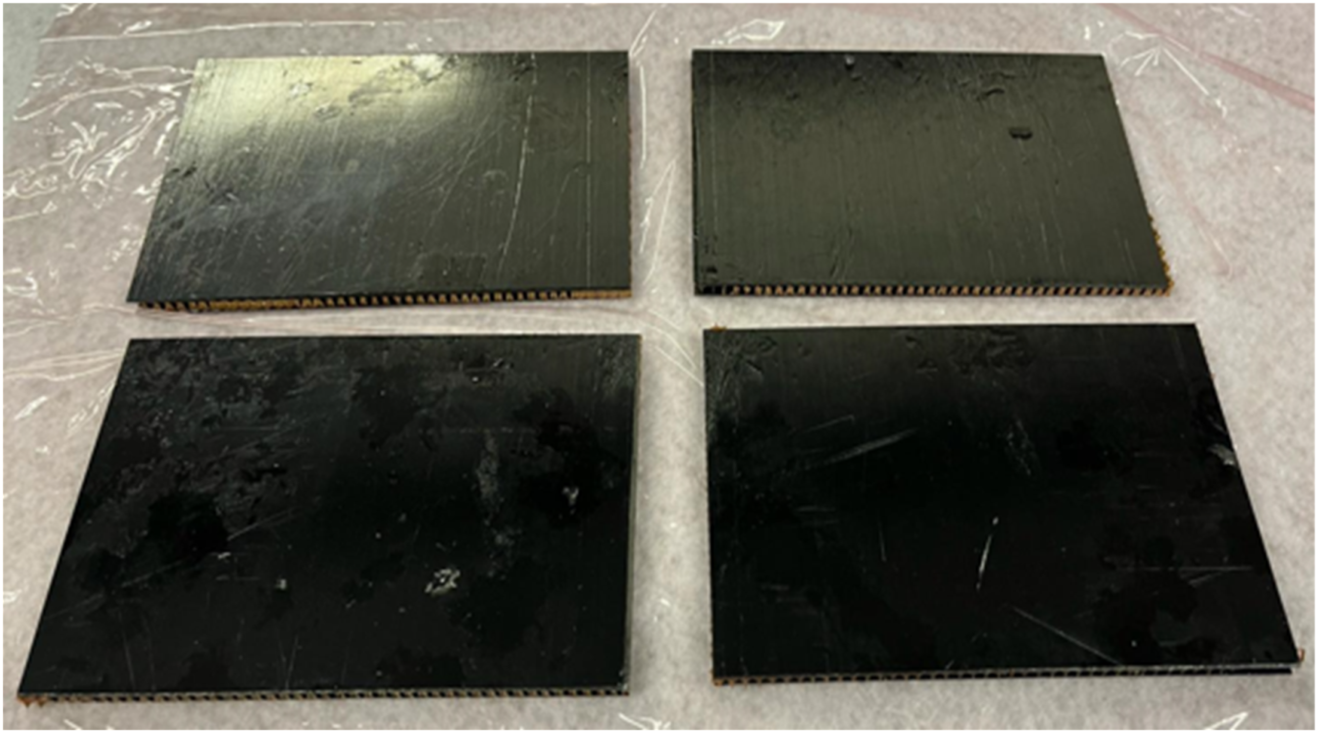
Test set-up and procedure
The most frequently conducted mechanical tests on sandwich composites are measurements of compressive strength, three-point bending test, and impact tests. 29 Quasi-static loading or penetration tests, falling under the category of compressive strength measurements and are pivotal in analysing the mechanical behaviour of sandwich composite panels.
To conduct this test on the fabricated samples, a Tinius Olsen universal testing machine (UTM) equipped with an indenter, as illustrated in Figure 5 was utilised. A standard 12 mm diameter indenter was employed to ensure uniform distribution of the load exerted by the machine. To secure the sample in place during the test and prevent any movement, a dedicated test rig, depicted in Figure 6 was employed. This rig provided stability and ensured consistent testing conditions throughout the duration of the experiment. For safety precautions, a protective shield was positioned in front of the test section to shield against any potential debris ejected during the experiment. Quasi-static loading test set up. Test rig.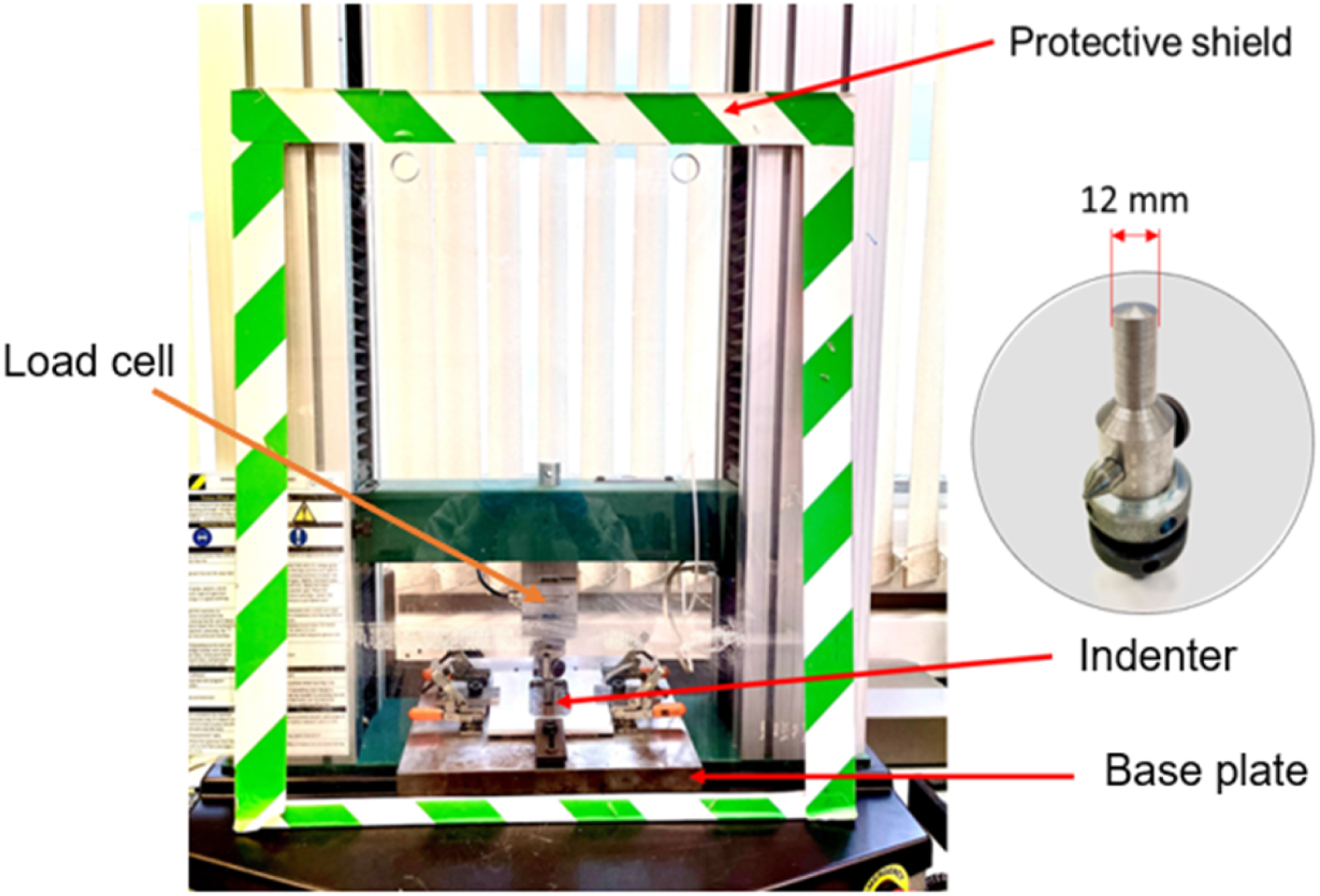
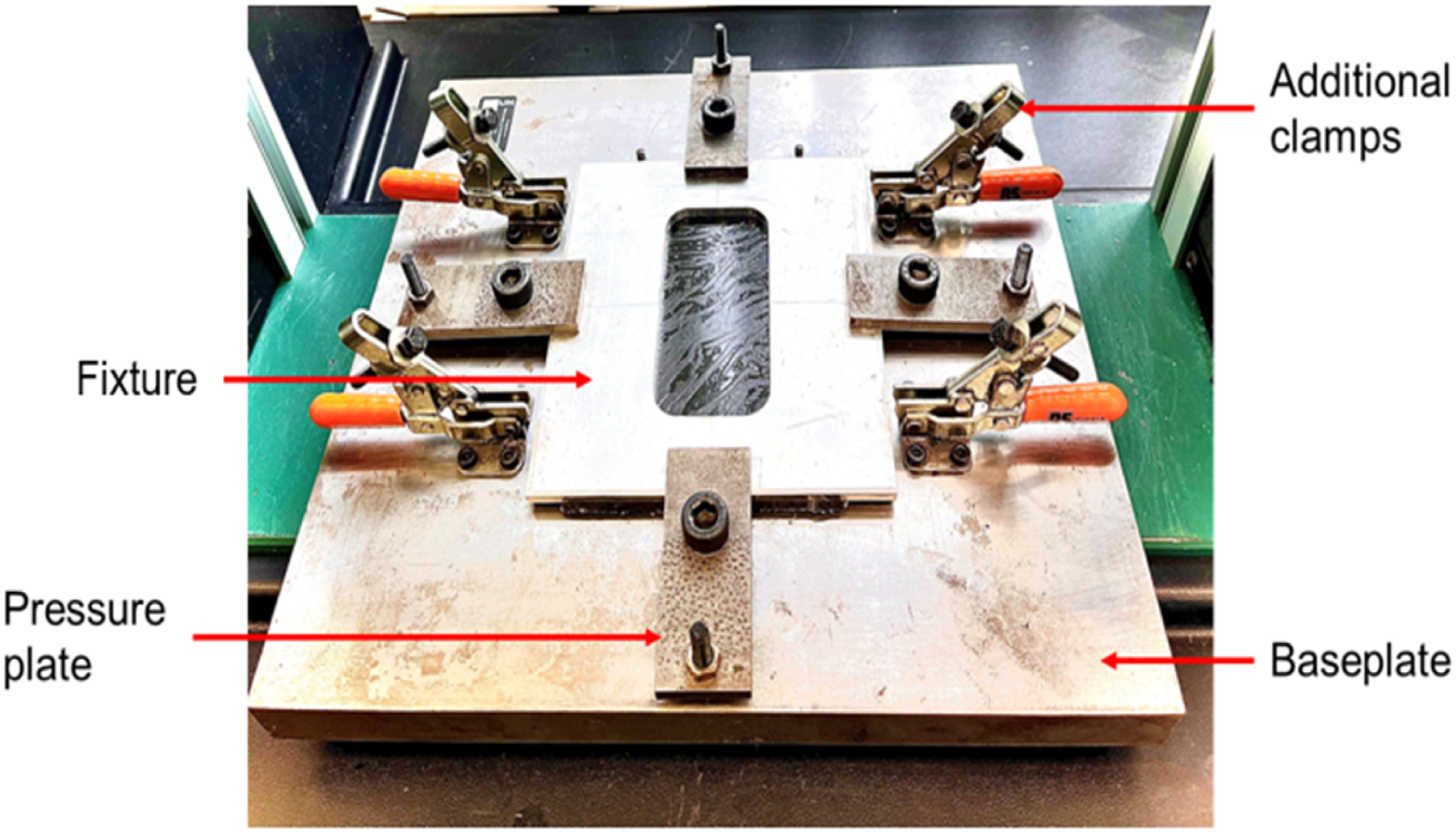
The test rig comprised of a baseplate for supporting the test sample, featuring a central rectangular aperture. On top of the test sample is a fixture with rectangular hole held by four pressure plates applied through screw bolts. Additionally, the test rig has extra toggle clamps. Before testing, the thickness of each sample was measured using a digital vernier calliper. Five readings were taken at different locations on the surface, and the average value was calculated. Subsequently, the indenter was gently lowered closer to the surface of the sample, and it was ensured that the indenter was centrally aligned with the sample.
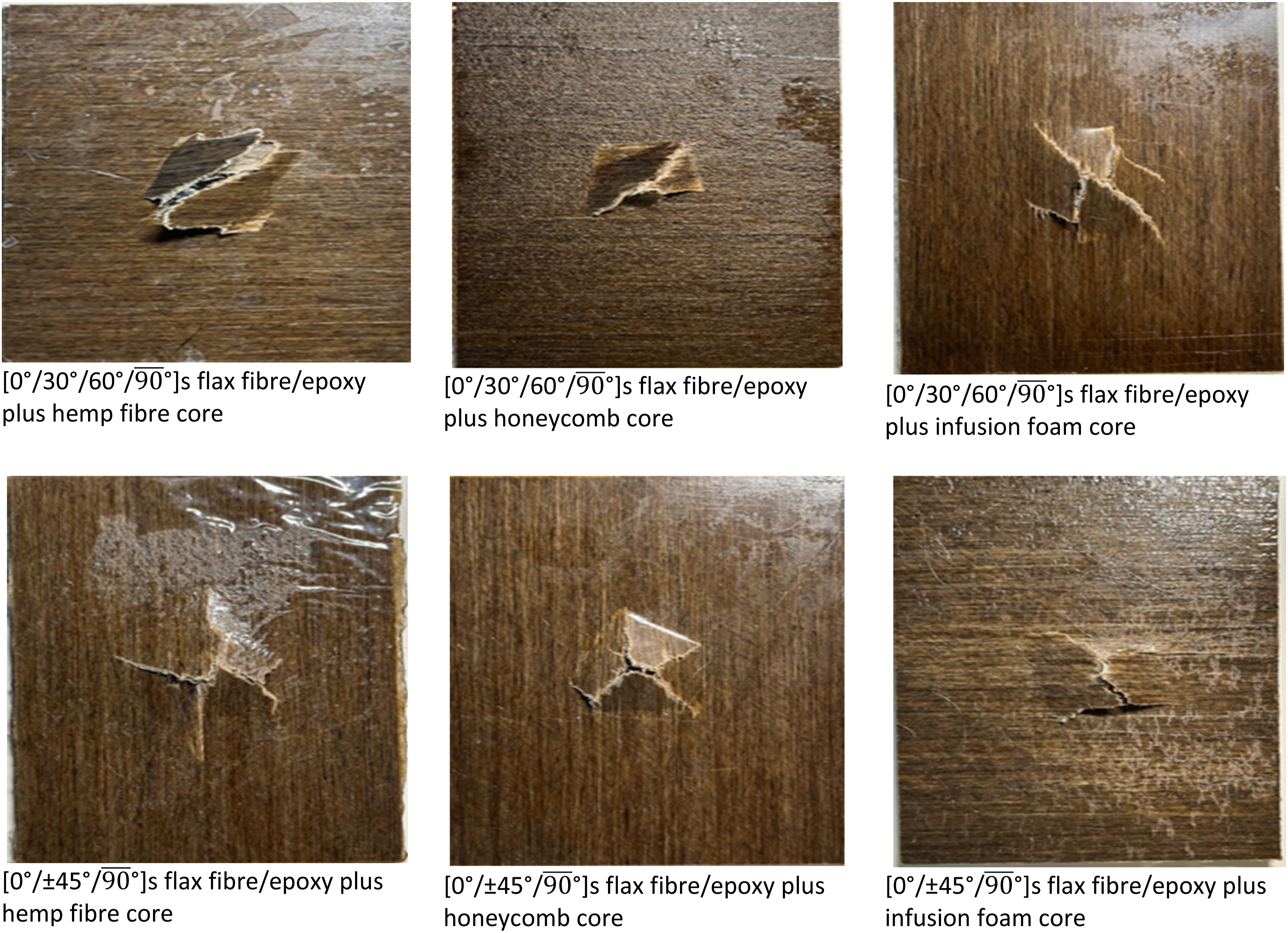
The test machine has a maximum loading capacity of 25 kN and the samples were loaded at a crosshead speed of 10 mm/min. During the test the resistive force exerted by the sample on the indenter is detected by the load cell and is measured as a function the displacement of the loading point. The indenter was loaded on the sample till penetration. The complete puncturing of the material was indicated by a distinct noise. The indenter was then halted from further penetration and gently retracted. This process was repeated for all the manufactured samples. The tested samples were examined through visual inspection and macro-photographs of the fracture zones.
Typical test result data analysis and phases of failure
The data collected by the software included the reactive forces on the indenter by the test sample, measured in Newtons, in relation to the position of the intender, measured in millimetres. The collected data was subsequently normalised based on the thickness of the corresponding sample. The data was normalised to facilitate a comparative analysis of the mechanical properties per unit millimetre of the manufactured material. The typical normalised values for force and displacement data plotted on a graph, is illustrated in Figure 7, depicting the phases of the penetration and perforation process that is elastic deformation, damage, and friction. Illustration of force versus displacement graph, with indenter position indicated, for each phase.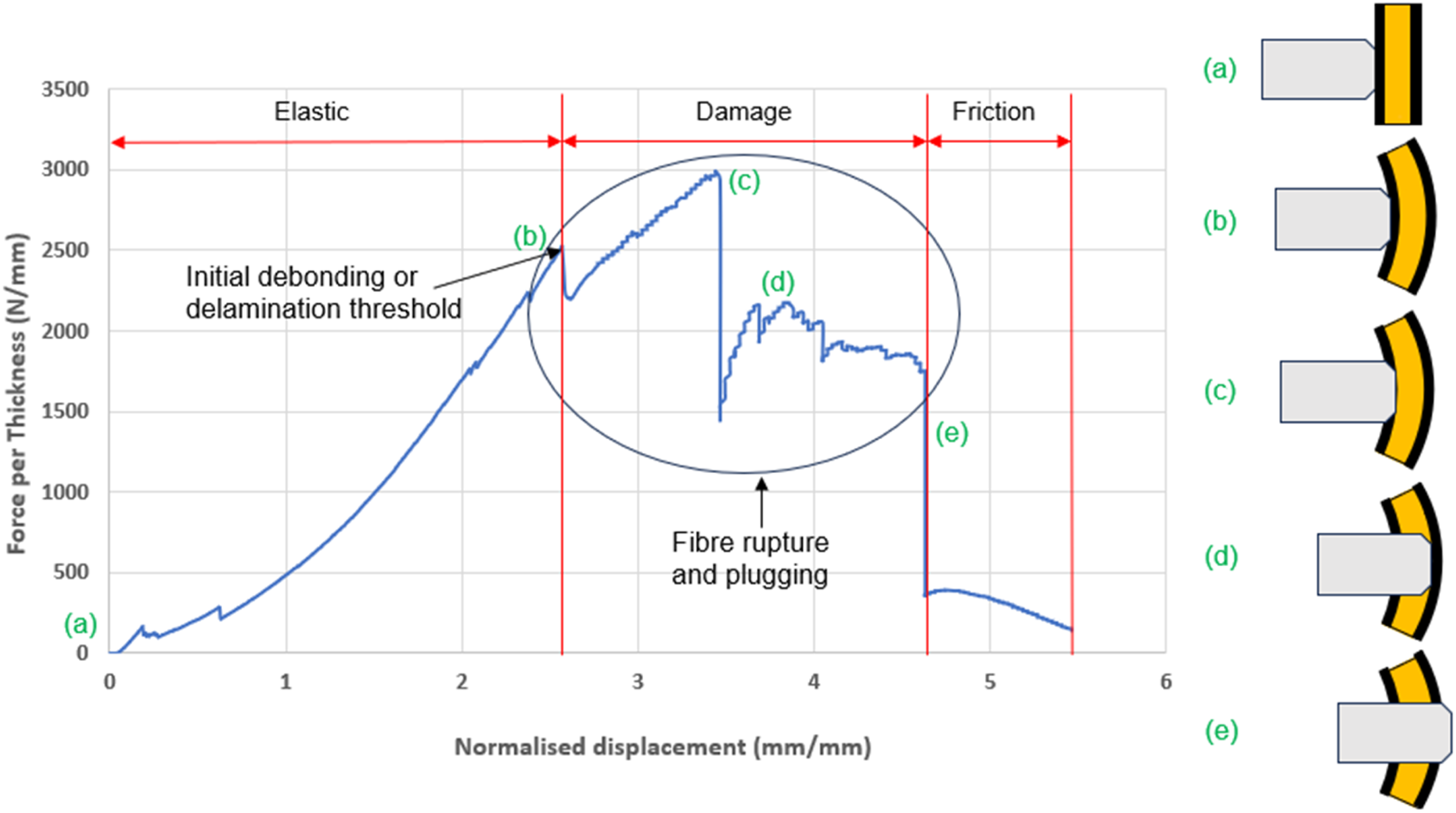
During the elastic phase, characterised by a linear or near-linear increase in force with displacement, the material is likely to undergo matrix cracking and deformation as the intender penetrates. As the loading progress the material reaches its maximum load-bearing capacity. Subsequently, in the damage phase, further penetration leads to material fracture and failure. This is often accompanied by fibre rupture and plugging, where fibres obstruct the indenter’s path. Figure 7 depicts the different intender positions. Initially, at position (a), the indenter closely aligns with the material’s surface. As force increases, the indenter bends the material causing some damage likely to be delamination at (b). The indenter penetrates the first layer of the sandwich composite at position (c), where it reaches its ultimate force. The loading on the structure keeps increasing until the indenter fully penetrates the core material at (d), and the lower skin at (e), thereby completing the test phase, where is seen the final drop in the load depicting the friction between the indenter surface and the test material.
Fibre breakage is expected in the second stage of the loading response history and is associated with the sudden load drop. This failure is also accompanied by fibre pull out 30 occurring after fibre fracture and is seen as the fibre leaves the matrix if viewed by a cut through the section damage. To quantify the total energy absorbed by the material up to complete penetration during the loading test, the trapezoidal rule was used to calculate the area under the force-displacement curve.
Experimental results
To investigate the characteristics of the sandwich panel under the low speed loading the sample was clamped round the boundaries and under the indentation load through the central point using the universal testing machine. The movement of the cross head applying the loading was 10 mm/min. The system measures the load – displacement response from the resistive force of the test sample to the loading.
Figures 8–11 shows the load-displacement graphs of the composite plates. It provides insights into the material’s stiffness, strength, and failure behaviour under load. The graph typically shows a near linear relationship initially, depicting some elastic behaviour, followed by a nonlinear region as damage evolves the structure and it eventually fails. The plotted data were normalised with the sample thickness for better comparison of the various characteristics. Caprino et al.
31
highlighted the significance of these curves as they give useful information about the damage phenomenon and the response of the structures. Representative loading response for [0°/30°/60°/ Representative loading response for [0°/±45°/ Representative loading response for [0°/30°/60°/ Representative loading response for [0°/±45°/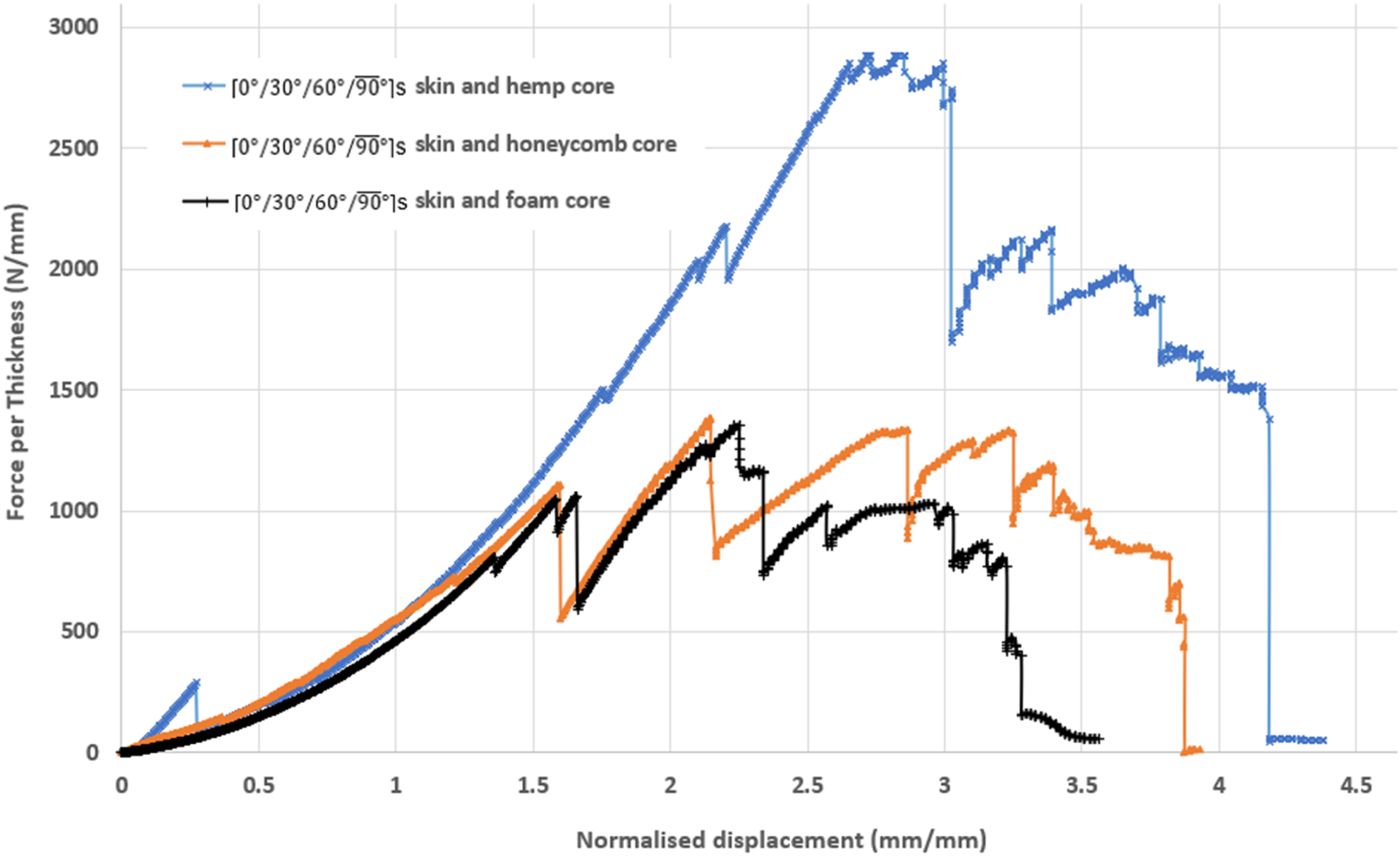
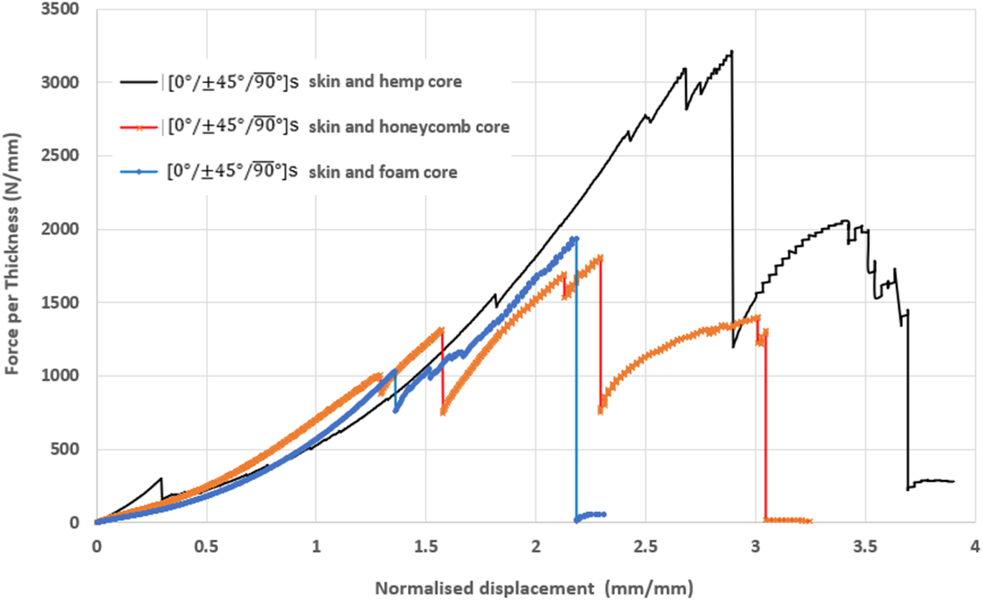
The load – displacement graphs of the sandwich plates of [0°/30°/60°/
Comparing the response in Figures 8 and 9 shows the difference between the half layup spiral configuration [0°/30°/60°/
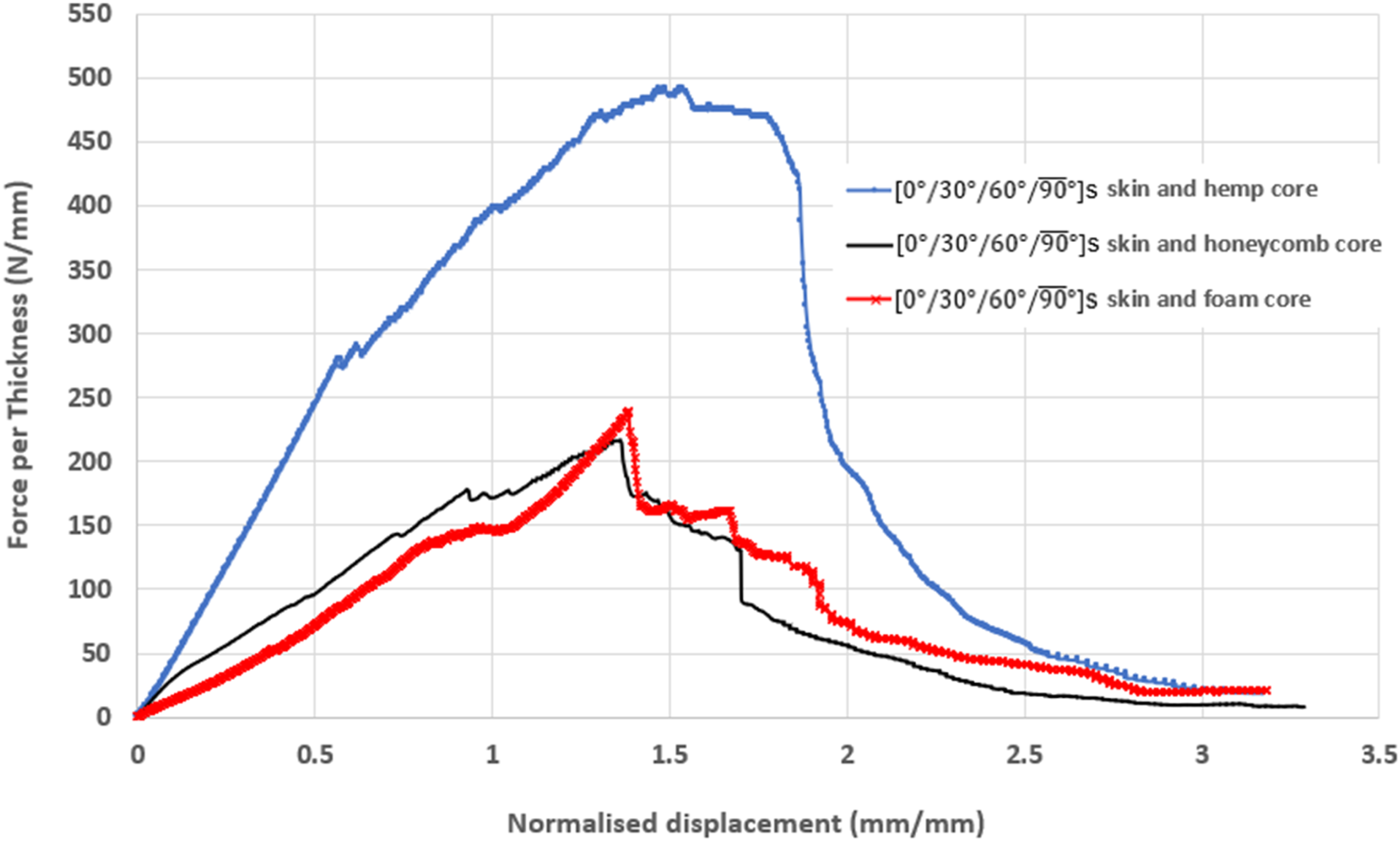
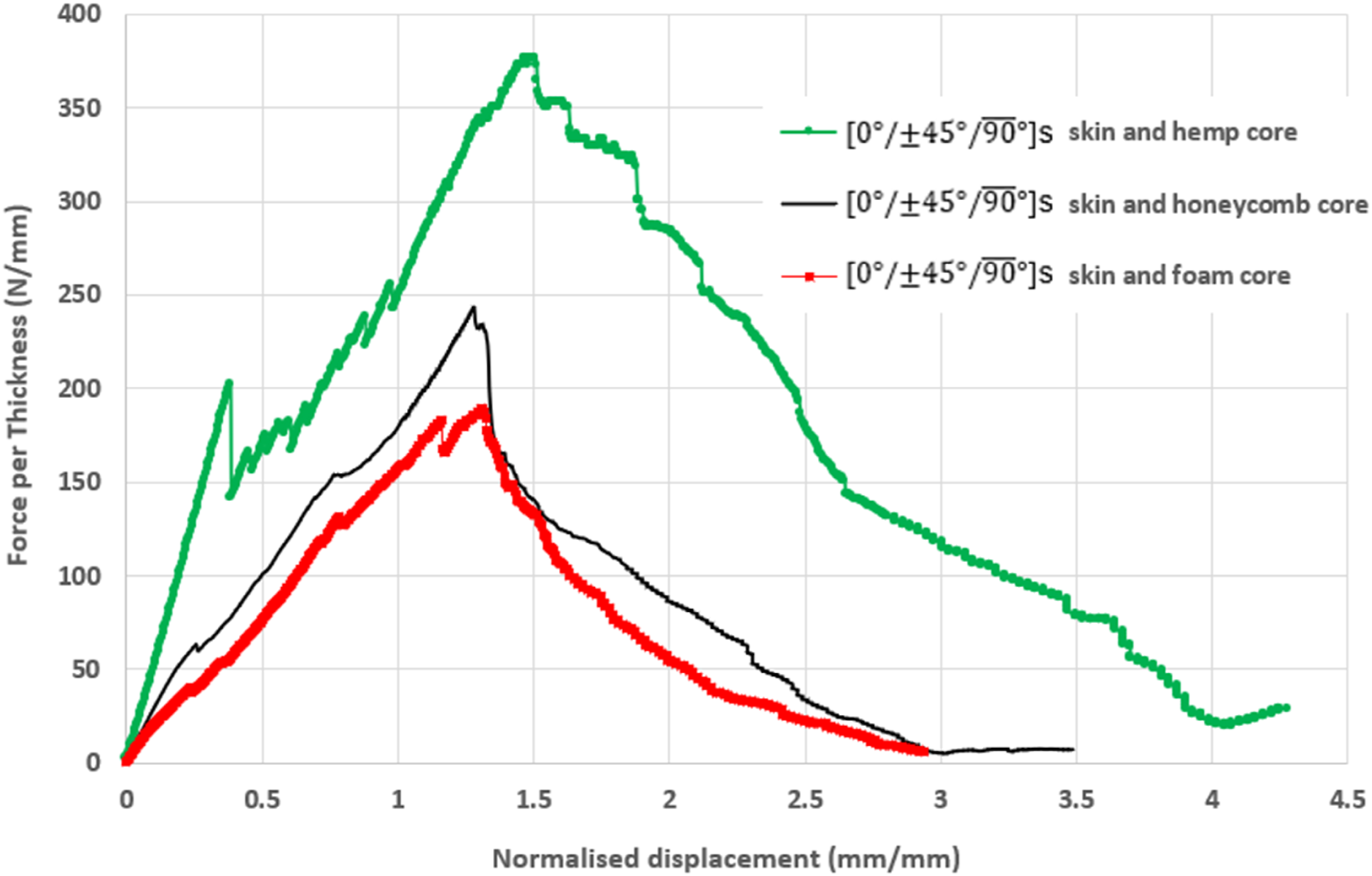
The response of the sandwich plates with flax fibre reinforced polymer laminate skins are quite different compared to the ones with carbon fibre as reinforcement on the skin structure as shown in Figures 10 and 11. This is likely because of the relatively better ductility of the natural fibres compared to synthetic ones. Carbon is mainly designed to withstand high rigidity and strength at the cost of ductility, while the use of natural fibres has the advantage of reducing the environmental impact at end of the life cycle.
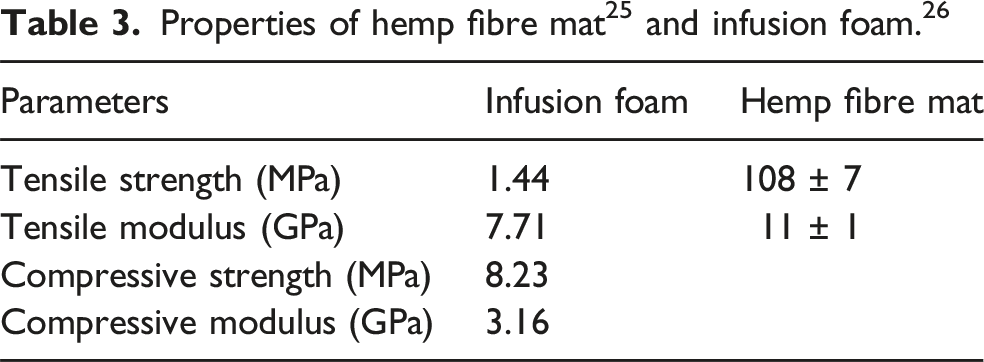
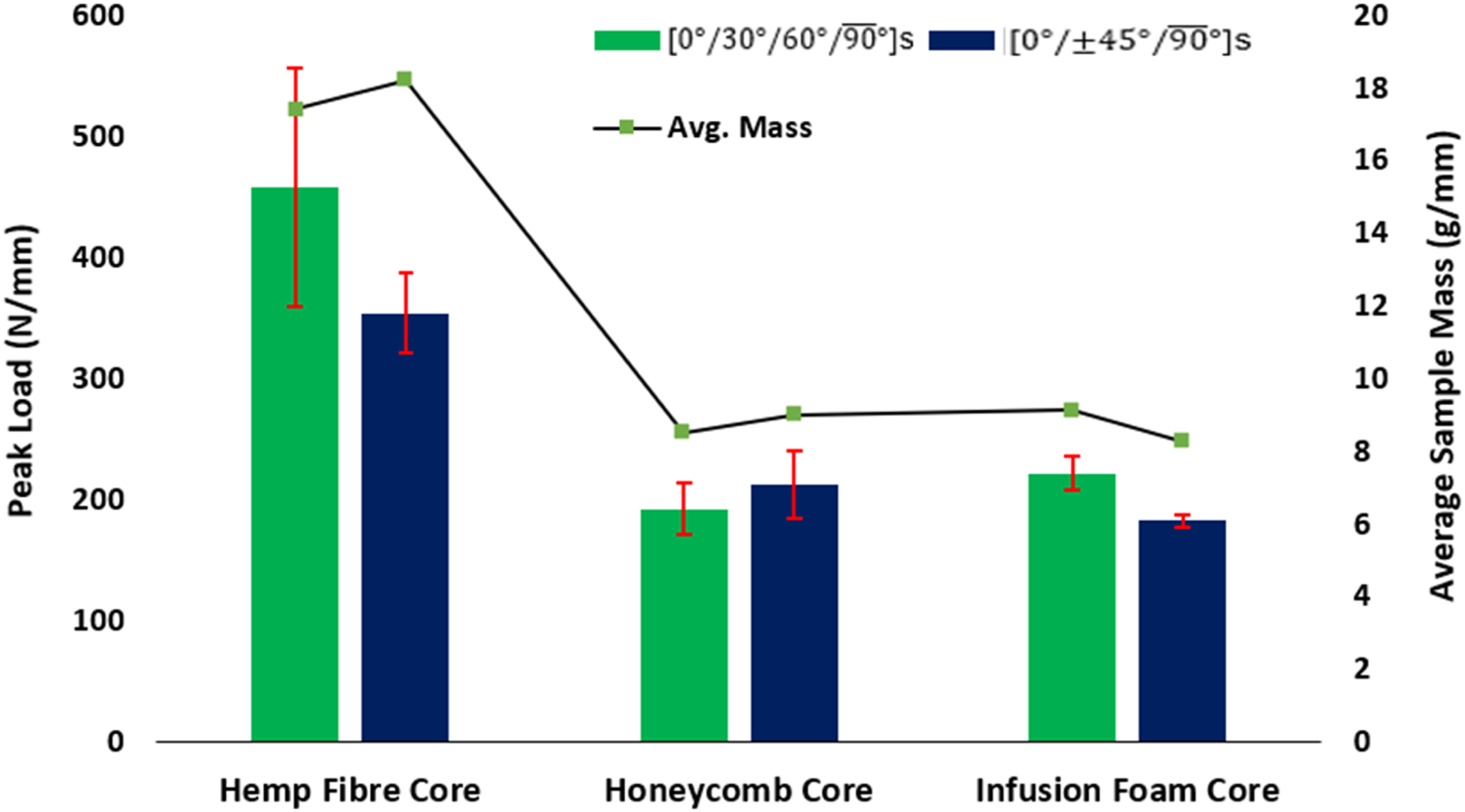
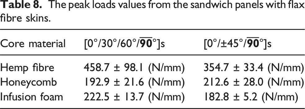
In Figures 10 and 11, the graphs rise to some peak value and then gradually drops to zero force value with little or no sharp drop of the loading indicating no major damage in the structure but lose of strength. The characteristics of the plots are of course because the different stacking configurations of the laminates and the different core materials of the sandwich structure. The average peak loads of [0°/30°/60°/90°]s flax fibre reinforced skin with hemp as the core as shown in Figure 10 is significantly higher than the ones with foam and aramid paper honeycomb materials. The values are respectively 459 N/mm, 222 N/mm and 193 N/mm this is because of the high strength of hemp (108 MPa) compared to the foam (1.44 MPa) and honeycomb (2.4 MPa) materials as obtained from the data sheet on the manufacturer’s website.25–27 In Figure 11 is the comparison of the response of the sandwich plate with the quasi-isotropic lay-up and the different core materials. The one with [0°/±45°/
Strength analysis of the structures
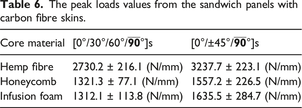
The mean values for peak loads and energy absorption determined from force-displacement curves of sandwich composites were plotted in a bar chart. In addition to displaying mean values, the graphs also present the error bars of four repeat test per sample indicating the standard deviations (Figures 12 and 13). Peak loads observed in sandwich panels with carbon fibre skins. Peak loads observed in sandwich panels with flax fibre skins.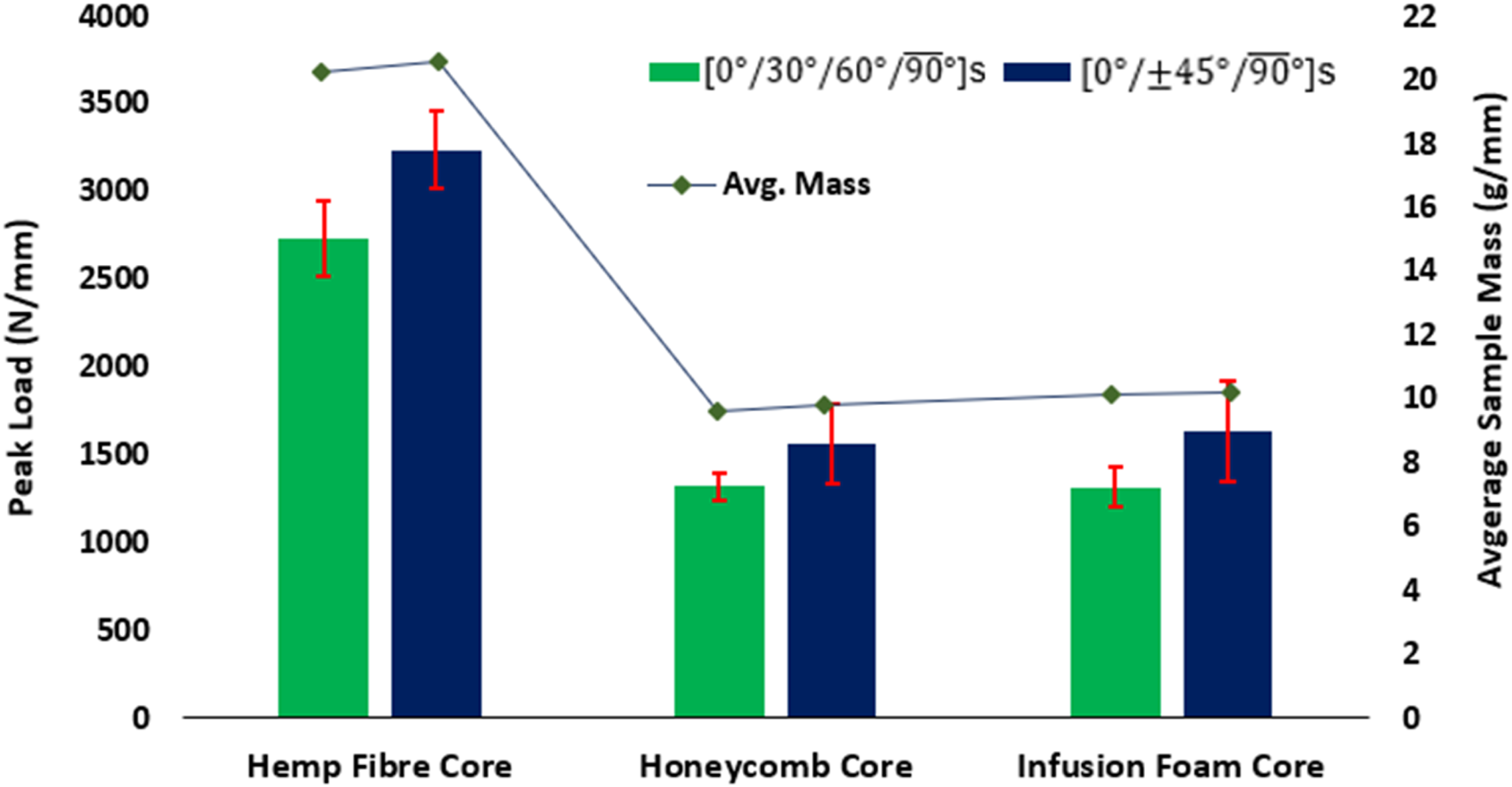
The peak loads values from the sandwich panels with carbon fibre skins.
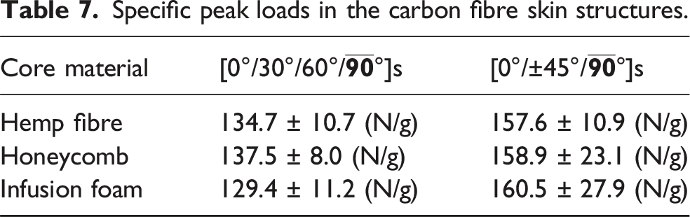
Specific peak loads in the carbon fibre skin structures.
The peak loads values from the sandwich panels with flax fibre skins.
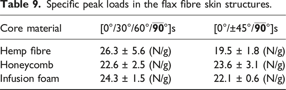
Specific peak loads in the flax fibre skin structures.
Comparison of the energy absorption
The data obtained from the quasi-static loading test on the samples were plotted as force-displacement curve and the area under these graphs were estimated using trapezoidal approach, which represents the work done by the indenter on the samples. This is equivalent to the energy absorbed and dissipated by the samples.
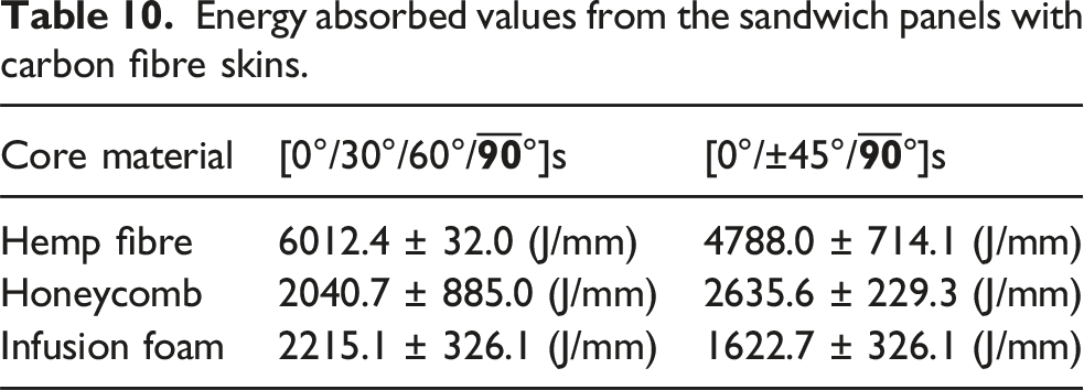
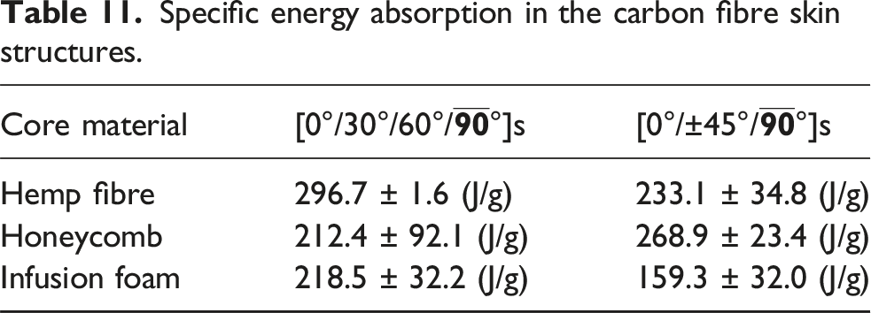
Figure 14 presents the data for the energy absorbed by samples with carbon fibres as reinforcement in the skin structures and the values of the absorbed energy shown in Table 10. Specific energy absorbed data known as the energy absorbed/dissipated per unit mass of structures are presented in Table 11. The structure with hemp as the core and [0°/30°/60°/ Energy absorbed by sandwich panels with carbon fibre skins normalised with the sample thickness. Energy absorbed values from the sandwich panels with carbon fibre skins. Specific energy absorption in the carbon fibre skin structures.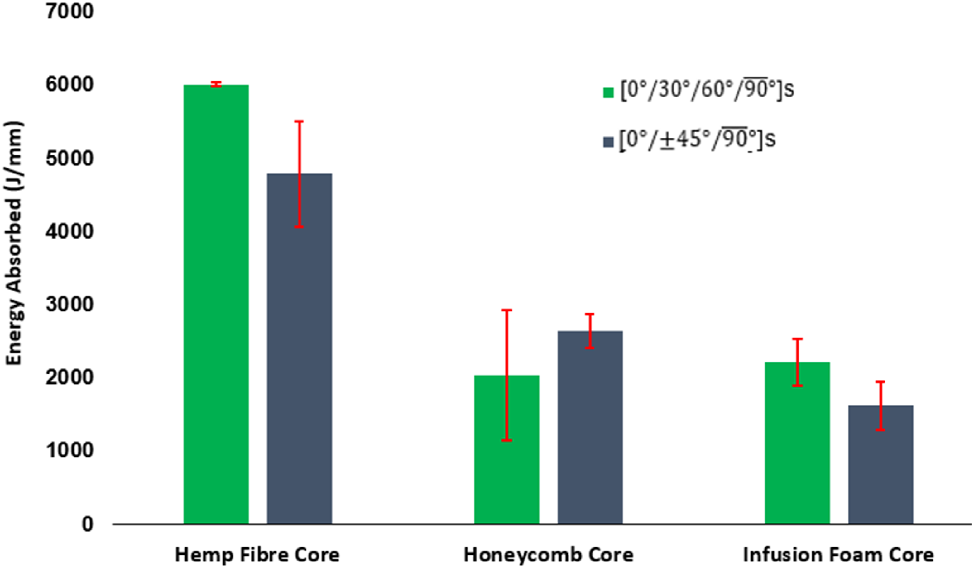
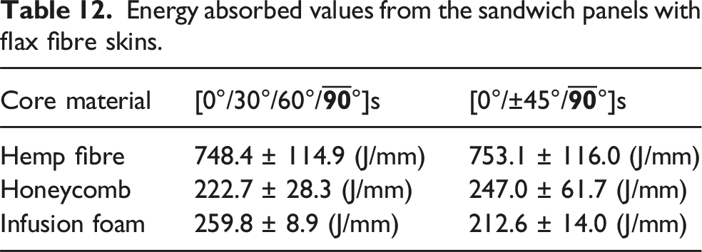
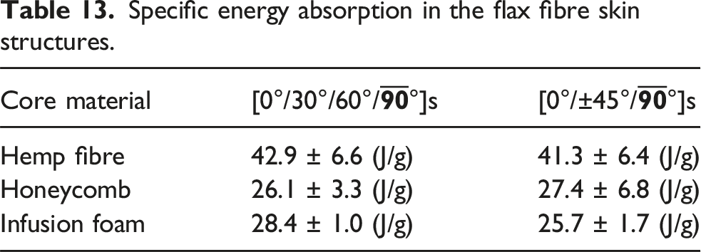
In Figure 15, the energy absorbed by samples with flax fibre as reinforcement of the skins is illustrated and the energy absorbed values presented in Table 12; also shown the Table 13 are the specific energy absorption data. A notable difference was observed between the energy absorbed values for flax fibre reinforced epoxy laminate skins with hemp fibre and those with other core materials. The energy absorbed by the flax fibre skin samples with foam and honeycomb core followed a different trend compared to the other one. The difference in the mean value of the energy absorbed is small [24 J/mm] for the honeycomb core sandwich samples. Energy absorbed by sandwich panels with flax fibre skins normalised with the sample thickness. Energy absorbed values from the sandwich panels with flax fibre skins. Specific energy absorption in the flax fibre skin structures.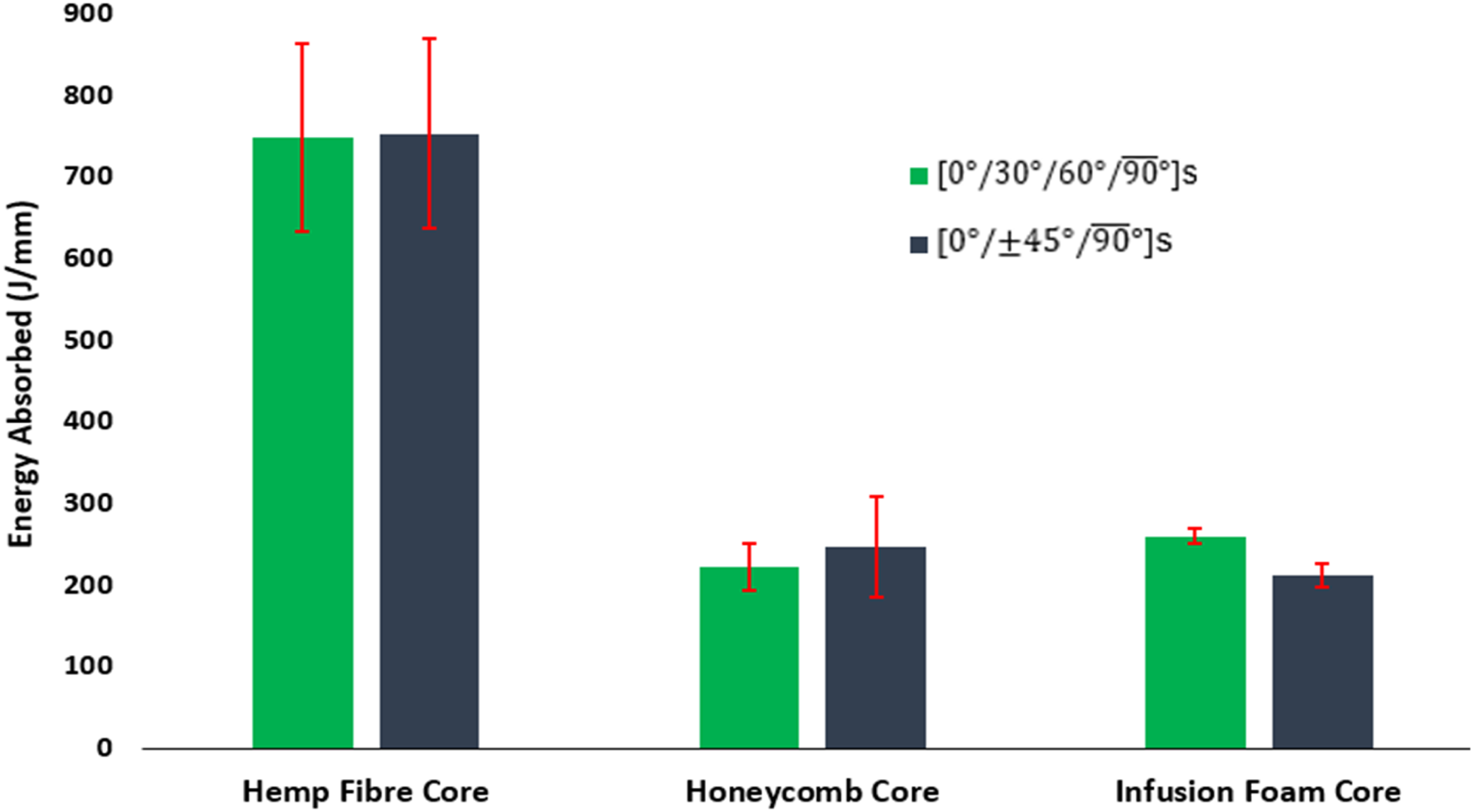
Examination of failure modes
Understanding the modes of failure will help in the optimisation of the composite design and drive innovation with the applications. Figure 16 show cases different failure modes observed in the cross-sectional view of the damage region of the sandwich panels. Predominantly, samples of stacking sequence [0°/30°/60°/ Cross section view photographs of the damages in the tested samples.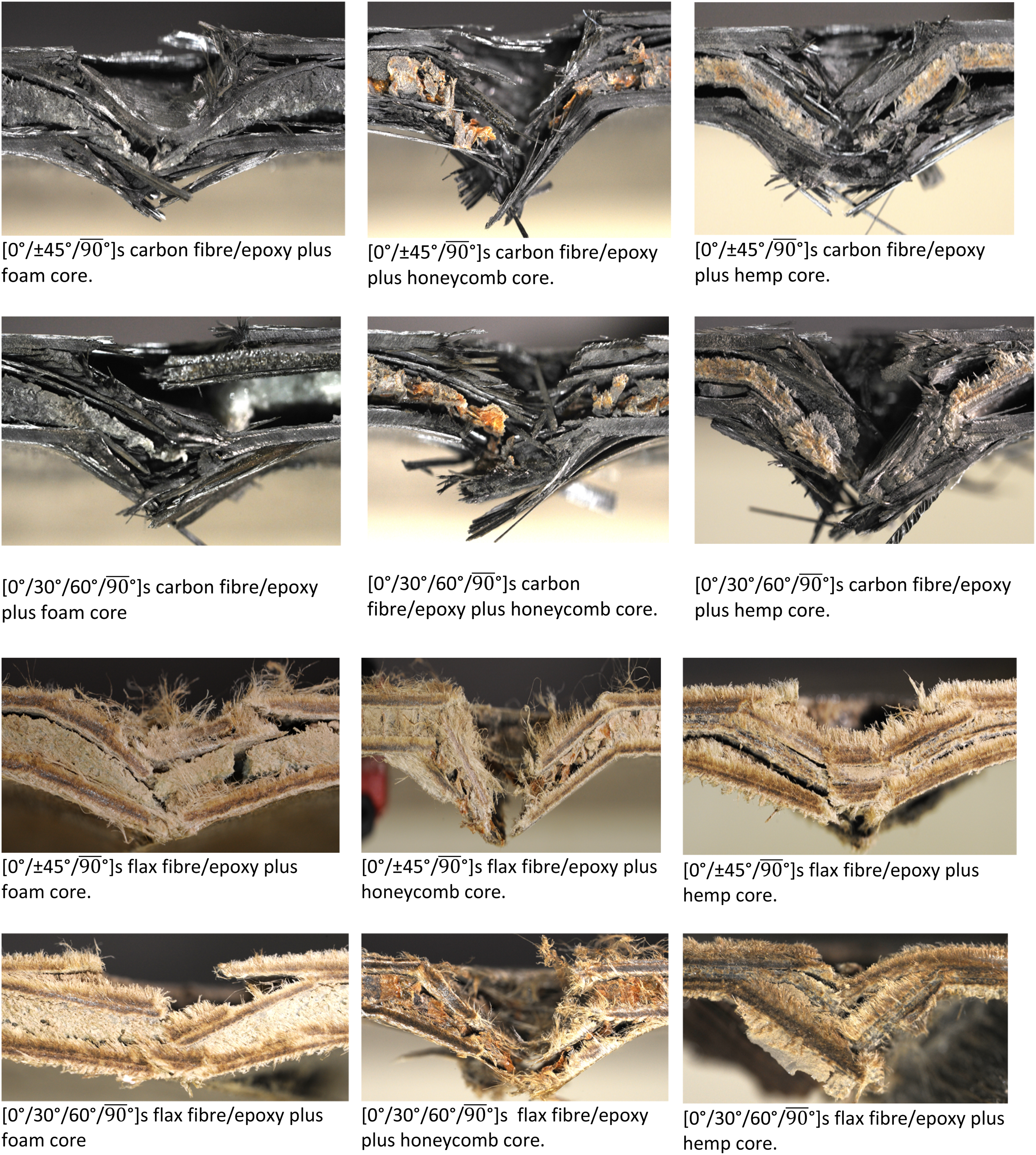
When a composite is loaded on a surface the resulting damage on the structure varies depending on the configuration, material type and the loading energy. This usually result to the front surface showing dents or indentations and matrix cracking. The indenter compresses the surface, cracking the matrix and breaking some of the fibres. In Figures 17 and 18 is illustrated the various failure modes on the rear surfaces of the tested sandwich structures. The rear surfaces are usually in tension due to the loading and failure modes shown include fibre breakage, fibre peel-out and matrix crack. Matrix cracking is one of the damages induced during quasi static loading and it is because to high stresses at the location of loading.
34
Comparing the rear surface damage characteristics of the sandwich plates with carbon fibre reinforce laminate skin in Figure 17 and the ones with flax fibre as reinforcement shown in Figure 18 the later was more localised. This is thought to be because of the strength carbon fibre, which is much higher than flax fibre. Rear surface damages of samples with carbon fibre reinforcement as the skin structure. Rear surface damages of samples with flax fibre reinforcement as the skin structure.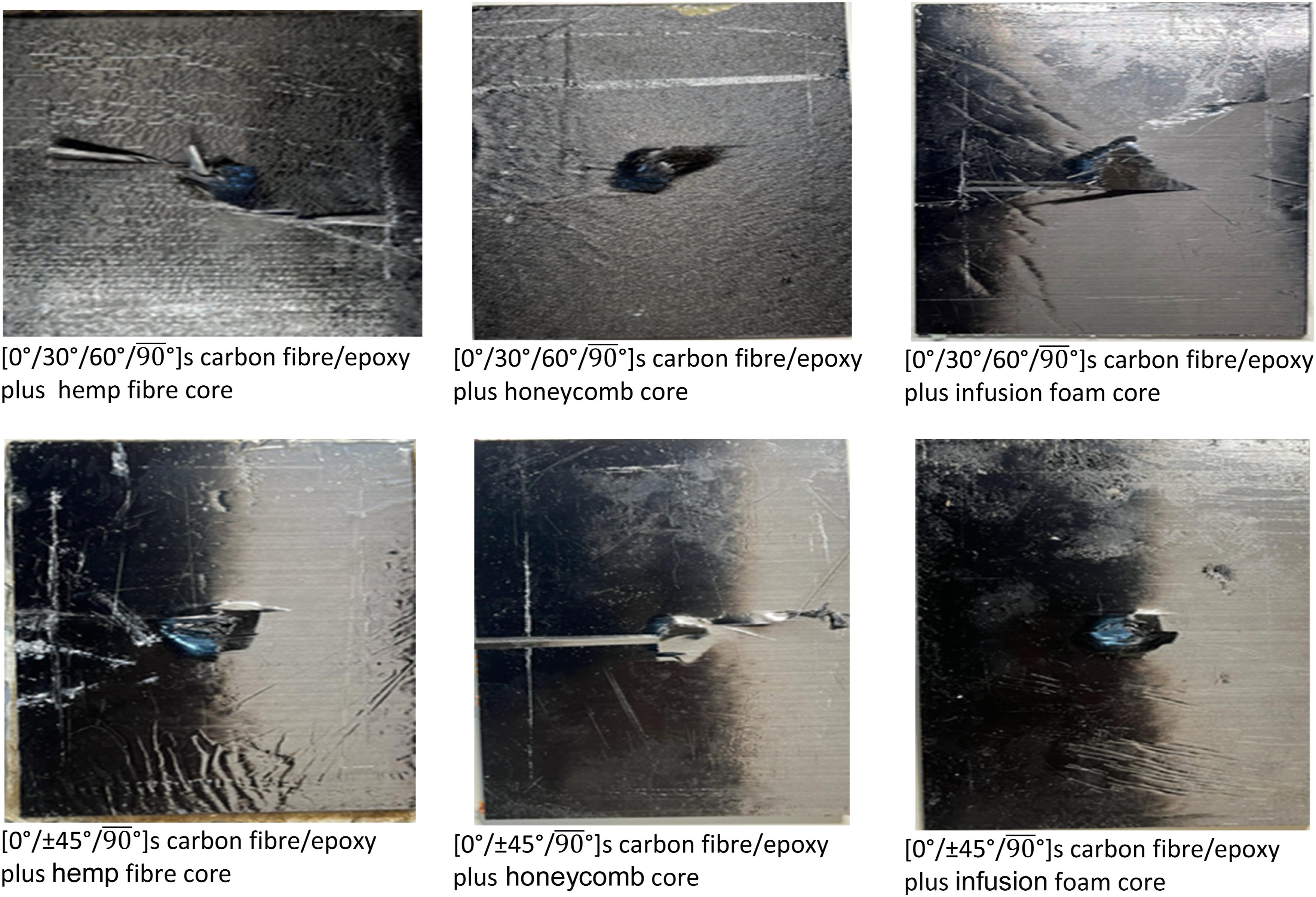
Debonding between core materials and skins was a common occurrence across all samples. The primary mode of failure for the samples with [0°/±45°/
While carbon fibre reinforced composites are brittle and linear elastic to failure, and this is depicted by the load – displacements graphs from the panels in Figures 8 and 9 by the sharp drops in the load. The panels with the skin reinforced with flax fibres shows gradual loss of the load from the peak to final failure (Figures 10 and 11). This distinction is evident in Figures 17 and 18 where the failure modes of the rear surfaces are illustrated.
Conclusion
The selection of materials, layup configuration, load path and stress distribution help engineers to optimise the structural design of the multi-layered panels for specific applications. With the purpose to contribute to development of sustainable structures, in this work sandwich composites with some percentages of biodegradable materials were manufactured and tested. These samples were tested under quasi-static loading to understand the behaviour of structures under slowly progressing load. The peak load and energy absorbed were estimated from the test data. Additionally, the tested samples were halved through the damage region, and the failure modes were observed.
Following the analysis of the test results, it was evident that the mechanical properties of composite sandwich panels largely depend on the characteristics of the reinforcement fibre being used for the skin laminates, stacking sequence of the laminate, choice of core material, and adhesion between the two. The mechanical properties of the samples featuring carbon fibre skins demonstrated superior characteristics such as the maximum load-bearing capacity and energy absorption compared to samples with flax fibre skins. The following inference was drawn from the results. • Different core materials exhibit distinct performance characteristics depending on the stacking sequence of the skin with which they are paired. For instance, honeycomb core demonstrated superior performance when paired with flax fibre skin in the stacking orientation [0°/±45°/ • Composite samples incorporating hemp fibre core demonstrated better performance across all samples when compared to those with other tested core materials. • It was evident that honeycomb and foam cores exhibited relatively better performance when paired with carbon fibre skins compared to flax fibre skins. • The samples incorporating honeycomb and foam core exhibited similar mechanical properties, indicating that either option could be utilised depending on the specific application requirements. However, it’s worth noting that samples with foam core tend to be slightly heavier than those with Nomex honeycomb core. • Delamination and fibre breakage emerged as the primary failure modes across all samples, with flax fibre samples exhibiting fibres pulling out in groups, in contrast to the individual pulling observed in carbon fibre samples. • Core crushing was observed in samples with honeycomb and foam cores.
Notably, the structures with flax fibres reinforced skin having 30° and 60° angle plies demonstrated good load bearing strength compared to the ones with ±45° fibre orientation, this could because of the spiral nature of the arrangement in the former.
Footnotes
Acknowledgements
The authors would like to acknowledge the University of Hertfordshire, which supported this study.
Funding
The authors disclosed receipt of the following financial support for the research, authorship, and/or publication of this article: This work was supported by the University of Hertfordshire.
Declaration of conflicting interests
The authors declared no potential conflicts of interest with respect to the research, authorship, and/or publication of this article.
Data Availability Statement
The raw and processed data that support the findings of this study are available from the corresponding author upon reasonable request.