
Abstract
The present contribution is concerned with enhanced strategies for the integrity analysis of filament wound CFRP pressure vessels. In order to account for the effect of statistically distributed manufacturing induced imperfections, a probabilistic strategy is implemented. The imperfection location, size and geometry together with the corresponding probability distributions are determined in non-destructive evaluations of different reference vessels using X-ray computed tomography. The impact of a set of selected relevant imperfections onto the strengths in the different material directions is analysed numerically in a multiscale analysis. For assessment on the structural level, a stochastic procedure is introduced which maps the imperfections according to their probability distributions onto a macroscopic finite element model of the pressure vessel under investigation. The structural response till failure is evaluated using a customized continuum damage mechanics material model. In a sampling procedure, repeated analyses with different prescribed imperfection distributions are performed. The results are evaluated statistically, taking the individual probability of occurrence of the underlying imperfection situations into account. The method is applied in both, static burst and cyclic fatigue loading situations. The results are validated against an experimental data base concerning coupon experiments and full-scale burst experiments on reference vessels.
Keywords
Introduction
Filament wound type 3 and 4 pressure vessels with metallic or polymeric liner and a load-carrying CFRP overwrap form essential elements for a developing hydrogen technology. They may serve as fuel vessels in all areas of road, rail and other types of ground transportation or as propellant vessels in aerospace technology. Further, they may be used as transport vessels or for road, rail, and sea transport or as stationary storage vessels. Due to the low volume specific energy content of gaseous hydrogen at ambient pressure and temperature, high pressures are required for storage at ambient temperature, imposing high requirements on the structural assessment during the design process in order to guarantee structural integrity at reasonable weights (Lenoe and Neal 1 ). Indeed – although this technological field requires rather high standards – the use of filament wound CFRP pressure vessels is not restricted to hydrogen technology but may include storage and transport of other gaseous and liquid substances as well.
As for other fibre reinforced composites, filament wound composites contain specific inherently manufacturing induced imperfections which cannot be avoided and are considered in structural safety factors. These inherent imperfections need to be considered in a high-precision numerical analysis in order to achieve the full utilization of the materials light weight potential. Among the manufacturing induced imperfections, fibre waviness of the inner plies might be induced by winding of the outer plies. Hörrmann et al. 2 showed in an experimental and numerical study that this waviness might trigger the development of matrix agglomeration with pronounced effects on the fatigue resistance. Further, they might affect the tendency towards delamination as shown by Lemanski et al. 3 Altmann et al. 4 proposed an analytical model based on Puck’s criterion to assess the effect of wavy fibres on the material integrity. Further to wavy fibre orientations, overall misorientations may occur. In this context, for example Falcó et al. 5 showed that already misalignments of a few degrees may result in a significant loss in stress carrying capacity. These misalignments may be induced by inaccuracies during the manufacturing process and may cause secondary imperfections such as undesired overlaps and gaps in the CFRP stacks as it has been shown by. Croft et al. 6 or Lan et al. 7 for tape laying processes.
Other relevant inherent imperfections may be the formation of fibre or matrix agglomerations or pores due to incomplete matrix wetting or infiltration. The effects of fibre agglomerations have been studied on the micromechanical level for example by Fast et al. 8 or Gommer et al. 9 using a microstructural simulation of the effect of the observed imperfections on the macroscopic material response. A similar study concerning the effects of pores had been provided before by Huang and Talreja. 10 Effects of incomplete infiltrations were studied by Baranger et al. 11 Further to the mentioned imperfection types, other types of specific manufacturing induced imperfections may develop in the filament winding process. In the present study, worm pores and fiber misalignments were detected as the most important imperfections for filament wound material.
All mentioned imperfections have in common that they are statistically distributed through the material. Depending on the imperfection type, the distribution can be uniform or non-uniform following other types of probability distribution. The need of probabilistic assessment in order to avoid unnecessarily large safety factors and thus over-conservative results with suboptimum utilization of the material has been pointed out by Lenoe and Neal 1 already in 1975. This finding is confirmed in more recent review papers on stochastic modelling of composite materials by Sriramula and Chryssanthopoulos 12 as well as by Mesogitis et al., 13 the latter especially directed to stochastic effects in composite material response induced by manufacturing imperfections. Nevertheless, only few contributions are available in the literature which really utilize stochastic methods. The few studies available include the already mentioned micromechanical studies by Fast et al. 8 and Gommer et al. 9 Chamis 14 analysed the material response of laminates with uncertain ply orientations, thicknesses, and constituent properties. Sutcliffe 15 provided a stochastic finite element analysis of compression tests on specimens with distributed uncertain fibre waviness. The present authors contributed a proposal for a stochastic material model for discontinuously fibre reinforced materials with uncertain fibre orientation distribution (Hohe et al. 16 ).
The uncertainties in material level lead to uncertainties in the structural response. Again, only few studies are available exceeding direct Monte-Carlo type approaches such as used by Cai et al. 17 for the simulation of filament wound composite sub-sea blow-out preventers. Lee et al. 18 provided a stochastic analysis of the effect of imperfections on the structural performance of stringer-stiffened shells. Approaches for the analysis of composite structures based on a Karhunen-Loève expansion of the material properties have been proposed by Soize 19 The present authors provided a probabilistic multiscale analysis from the material microstructure up to the macroscopic structural level for foam core sandwich structures (Beckmann and Hohe 20 ).
The present study is concerned with a stochastic approach for the analysis of the static and fatigue failure loads of filament wound CFRP pressure vessels. Based on a microstructural investigation using X-ray computed tomography, a catalogue of relevant imperfections has been elaborated in a previous contribution by part of the authors (Jatzlau et al.
21
). The effect of the most relevant among these imperfections on the local strength is determined here in a multiscale analysis of volume elements containing these imperfections. Subsequently, a mapping procedure is implemented to map these material inhomogeneities onto a structural (finite element) model of the pressure vessel, based on a predefined discretization of the (hyper-) space of the random variables as proposed earlier (Beckmann and Hohe
22
,
23
) in conjunction with the observed probability distributions of the random variables defining the imperfection distribution. The numerical results are validated against burst experiments on a reference vessel. The workflow for the stochastic integrity analysis is compiled schematically in Figure 1. Probabilistic simulation strategy.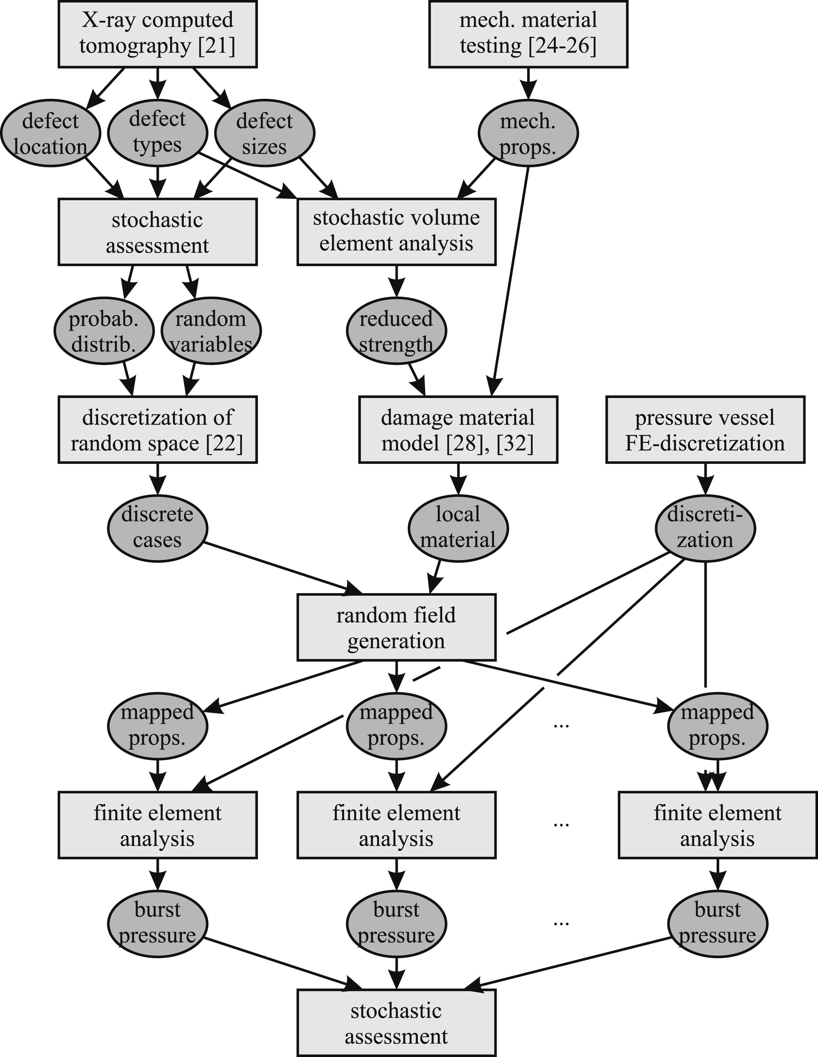
Material
Filament wound reference material
The reference material considered in the present study is a filament wound carbon fibre reinforced epoxy matrix material. The material was manufactured in an industrial filament winding process in order to ensure to ascertain the presence of relevant manufacturing induced imperfections to a realistic extent. Due to the filament winding process, the material consists of non-separable [±α] helical plies with different angles α.
The material for manufacture of coupon specimens for the basic characterization was supplied in form of large hoops with an inner diameter of 610 mm and a thickness of 10 mm. For the manufacture of unidirectionally fibre reinforced coupons, hoop winding only was used. Further, a hoop with [±45°] winding only was supplied for the manufacture of specimens for [±45°] tensile shear tests.
For validation experiments on structural level, two reference pressure vessels with a simplified stacking sequence were manufactured. The reference vessels had an internal diameter of approximately 290 mm and a length of approximately 800 mm, using a liner made of a polyamide material. The simplified stacking sequence consisted of an inner and outer hoop ply on the cylindrical part with an intermediate helical [±α]-ply over the cylindrical part and the caps with a nearly axial fibre orientation. The winding angle for this layer results from the length if the pressure vessel in conjunction with the width of the wound filaments together with the boss diameters. In the present case, the angle in the cylindrical portion of the vessel was approximately α ≈ 6° towards the axial direction. Over the domes, varying angles according to the dome geometry were obtained.
Manufacturing induced imperfections
The material was investigated for manufacturing induced imperfections using X-ray computed tomography. The investigations were performed on the reference vessels according to the last section as well as similar ones with different stacking sequence. Full details on the X-ray CT system are provided in a previous contribution (Jatzlau et al. 21 ).
Among the manufacturing induced imperfections of different type and size as detected in this study, worm pores according to Figure 2 were identified as the most relevant ones for the assessment of strength and integrity. The worm pores were of different lengths and diameters. They appear aligned with the fibres in the respective plies as observed in Figure 2. The worm pores were distributed randomly throughout the entire pressure vessel shell. Regarding their distribution through the shell thickness, a probability distribution with a clear preference towards the outer plies was detected. In addition to the worm pores, non-negligible fibre undulations and misalignments were detected. Exemplary results for the orientation density distributions are presented in Figure 2. Further to the worm pores and fiber misalignments, a variety of smaller imperfections were detected. However, compared to the large worm pores and the non-negligible fiber misalignments, they were considered as inherent material features and thus are not considered explicitly in the numerical study. Manufacturing induced imperfections in the reference material detected by X-ray computed tomography.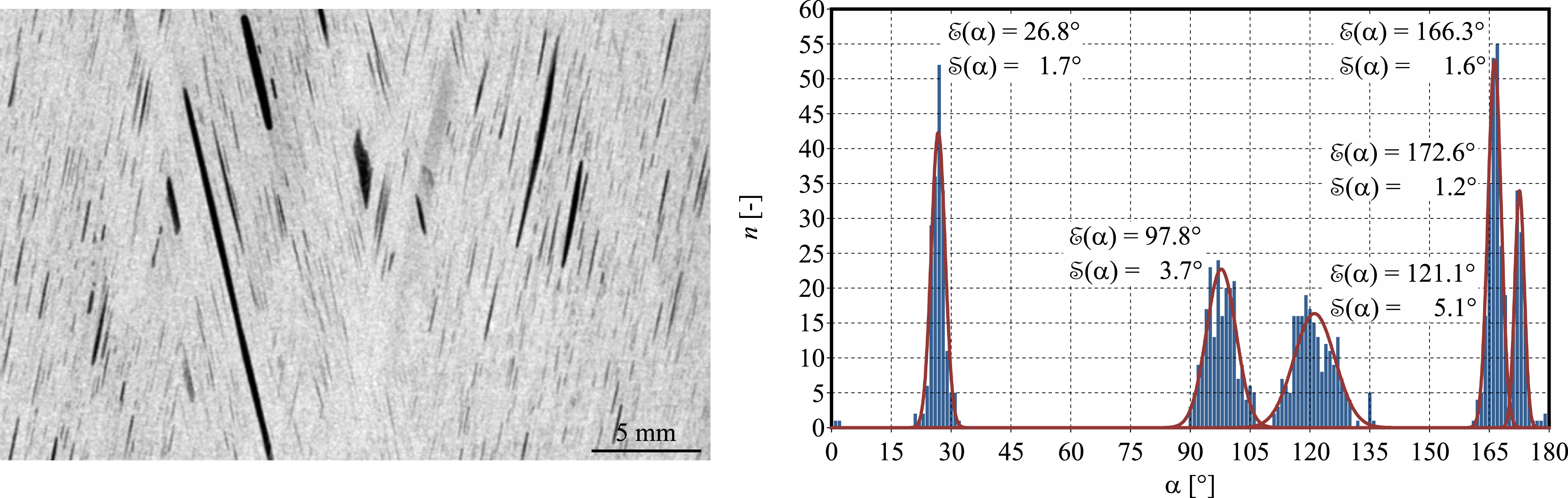
The size and the amount of worm pores identified in Figure 2 gives evidence for the necessity of a damage mechanics modelling of the material of the pressure vessel shell. The size and the amount of worm pores on one hand do not allow for accounting for them explicitly in a model for structural analysis. On the other hand, they cannot be neglected or considers as a homogeneously distributed material feature. Hence, a damage mechanical model considering them in a smeared manner appears to be advantageous.
The obvious stochastic distribution of the worm pores through the pressure vessel shell with an essentially non uniform probability distribution through the shell thickness together with the stochastic distribution of the local fibre angles around their nominal values strongly suggests the use of a stochastic approach for the numerical simulation of the structural response.
Experimental methods
Coupon experiments
The quasi-static mechanical response of the reference material was determined experimentally in tensile experiments within and perpendicular to the fibre direction as well as in [±45°] tensile shear experiments. The fatigue response was determined in tensile fatigue experiments perpendicular to the fibre direction. For the manufacture of the specimens, plane platelets were milled from the provided filament wound hoops. After milling and grinding the platelets to their desired thickness, the specimen contours were manufactured using waterjet cutting. The specimen dimensions and their positions in the provided filament wound hoops are sketched in Figure 3. To avoid specimen slip in the mechanical clamping system, the specimens to be tested at higher loads, i.e. the specimens to be tested within the fibre direction were supplied with tabs. Prior to testing, all specimens were conditioned to normal climate 23/50 according to ISO 291.
24
Specimen geometry and manufacture for characterization on coupon level.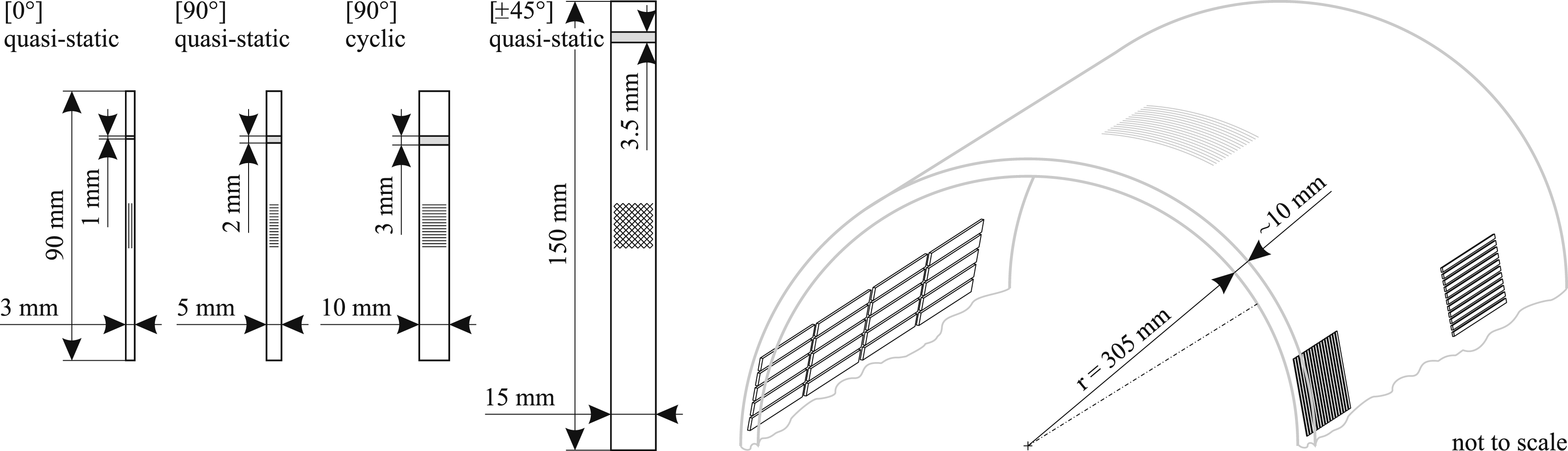
The static experiments within ([0°]) and perpendicular ([90°]) to the fiber direction were performed as far as possible according to or similar as described in ISO 527, 25 using an electromechanical Hegewald & Pescke inpekt 250 testing machine with a mechanical grip system. The same equipment was used for the [±45°] tensile shear experiments according to ISO 14129. 26 The specimens were loaded displacement controlled till failure at a constant cross-head velocity of 0.2 mm/min. Lower cross-head velocities than in the standards had to be used since the specimens had to be shorter than the standard specimens (Figure 3) in order to avoid curvature effects of the filament wound precursor as far as possible. Also, due to the smaller cross-section compared to the standard specimens, the stiffness ratio between the specimens and the loading device is smaller. Both effects would result in an increased strain rate if the standard cross-head velocity would be used. These effects are at least approximately compensated by the lower cross-head velocity used here. During the experiments, the longitudinal and transversal strain as well as the resulting force were continuously recorded using a biaxial clip-on extensometer and the internal load cell, respectively. The results were evaluated in terms of engineering stress-strain curves and the parameters derived thereof according to the respective test standards (ISO 527, 25 ISO 14129 26 ). A total of 10 specimens were tested in the individual test series, thus doubling the requirements of the respective test standards in order to provide a statistically more reliable data base. However, a few experiments did not provide valid results and therefore were excluded from the evaluation. All experiments were performed at ambient temperature.
The fatigue characterization was performed in tensile fatigue experiments similar to ASTM D 3479/D3479M. 27 The experiments were performed in a servo hydraulic MTS 858 Mini Bionix II under force control at individually determined load levels with a load ratio of R = σmin/σmax = 0.1. Since fatigue of pressure vessels is predominantly induced by filling cyles, the tests were performed in the low to intermediate cycle fatigue range between 100 and 105 cycles. Tests reaching more than 105 cycles were considered as run-outs. A total of 10 specimens was tested. All experiments were performed at a test frequency of 5 Hz. Again, the experiments were performed at ambient temperature. The results were evaluated in terms of a S-N curve. All static and cyclic coupon test results are provided in the resulrs section.
Burst experiments
In the burst experiments, two reference vessels were tested under internal pressure to provide a validation test for the numerical methods. Although the restriction to two tests only definitely limits the results in their statistical significance, the tests will provide at least a validation of the general method. The reference vessels were loaded by internal fluid (water) pressure, increased linearly till burst failure. During the experiments, the applied internal pressure was increased at a constant loading rate of approximately 1 bar/s. The burst experiments were performed at ambient temperature. In Figure 4, one of the reference vessels is presented prior to and after the burst experiments. Reference pressure vessel before and after burst test.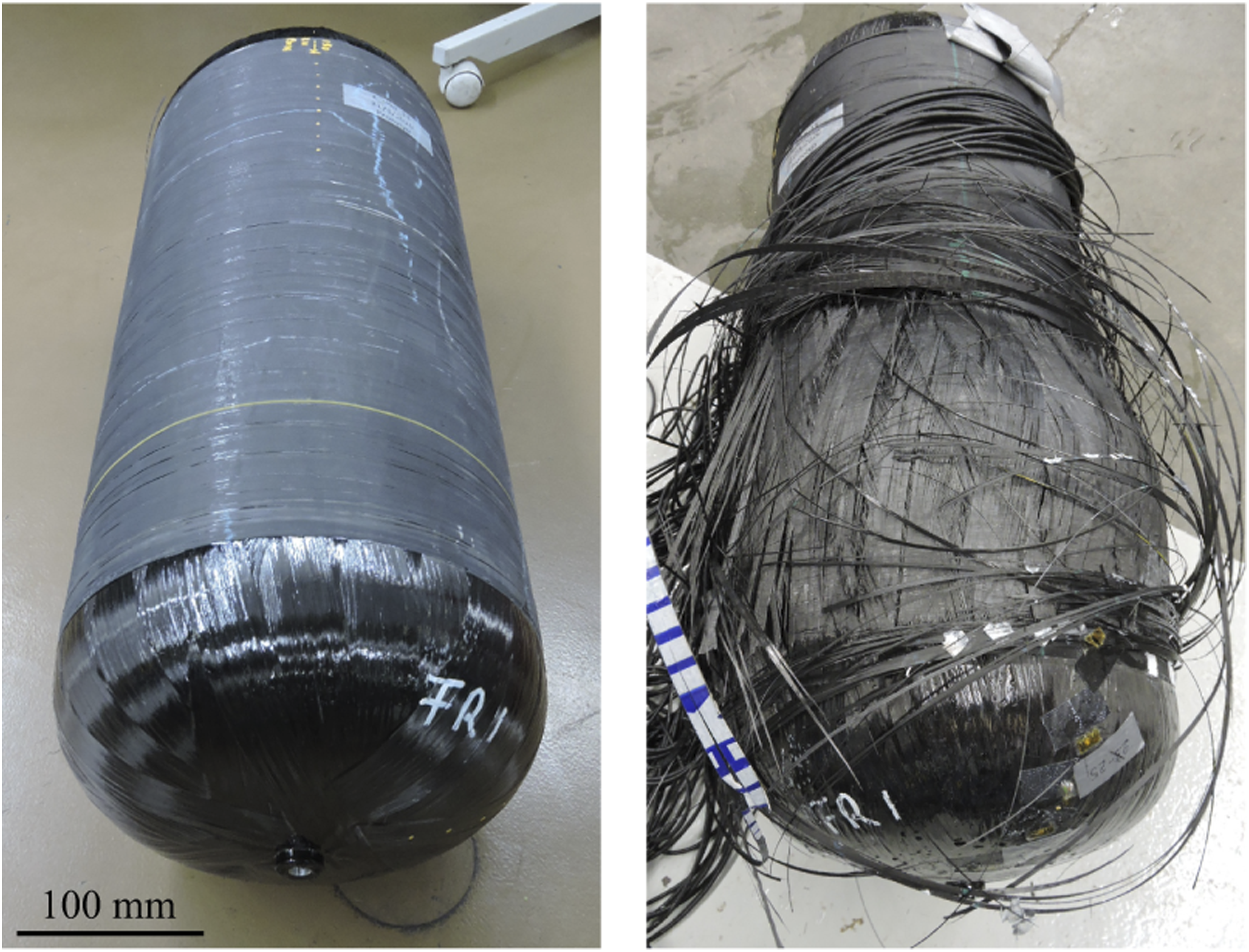
For the burst experiments, the reference vessels were instrumented with a total of 31 resistance strain gauges at different positions along the cylindrical part of the vessels as well as on their domes with a special interest directed to the transition region between the cylindrical part and the domes at both vessel ends. In order to enhance the statistical significance limited by the restriction to two experiments, the strain gauge positions were chosen such that a number of nominally similar positions, that is having the identical distance to the dome and cylinder interface at both vessel ends, were investigated. The strain gauges were applied in the axial and circumferential directions as well as under 45° to these directions. The test results are presented in the results section.
Numerical methods
Damage mechanics material model
The numerical integrity assessment of the pressure vessel was performed by means of a customized damage mechanics material model. The model has been derived in a similar version for short fibre composites (Abdul Hamid et al. 28 ). Here, the model is adopted and customized for application to filament wound unidirectionally fibre reinforced materials.
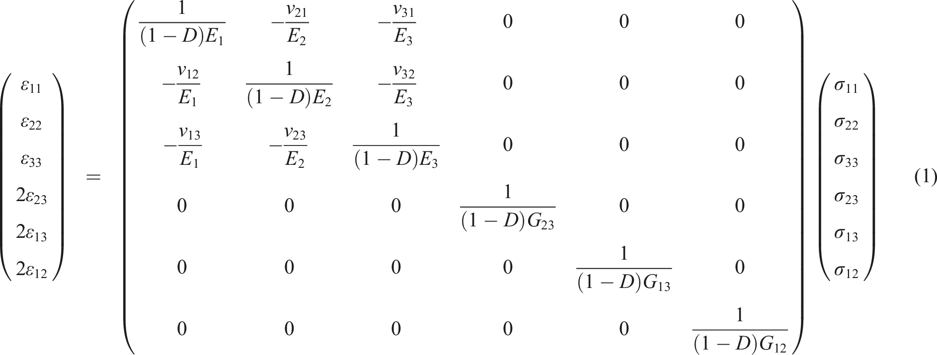
Considering the inherent predominantly linear and brittle response, the model is based on the classical linear elastic Hooke’s law in the orthotropic form. Thus, the formulation is related to the principal axes system of the material, requiring symmetry in all three spatial directions of a Cartesian coordinate system x
i
where x1, x2, and x3 are the axial, circumferential, and shell transversal directions respectively. Introducing damage effects in a similar manner as in Matzenmiller et al.’s
29
model, however, using a single damage variable D, results in

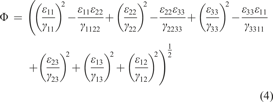
Static failure is assumed if any of the failure strains reaches a critical value. To account for interaction between the different failure modes, a strain-space version of the now classical Tsai-Hill failure envelope is employed, assuming an ellipsoidal surface in the six dimensional strain (hyper-) space to bound the uncritical elastic region. Thus, critical and uncritical strain states are classified according to Tsai-Hill type failure envelope re-formulated to two-dimensional strain space.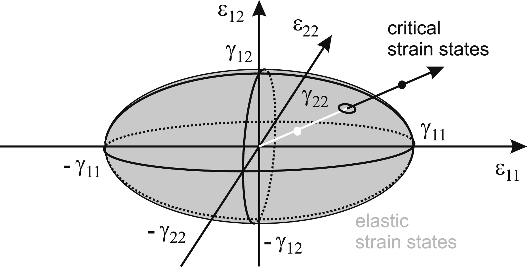
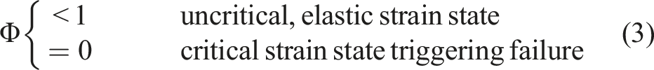
In the proposed damage mechanics material model, the approach of the strain state point ɛ
ij
at a specific material position towards the failure envelope (Figure 5) is assumed to drive the damage evolution. Thus, in the sense of Maimí et al.’s30,31 the damage evolution has to be a function


Assuming further that on the micromechanical level, the development of damage is related to the dissipation of microplastic work that is, a type of contained plasticity active well below the static yield limit and related with rather small plastic strain levels, and assuming that the microplasticity can be modelled by a Ramberg-Osgood type power law (Hohe et al.
32
), the damage evolution needs to be a power law functions of the strains. Therefore, a damage evolution function in the form
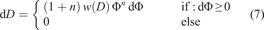
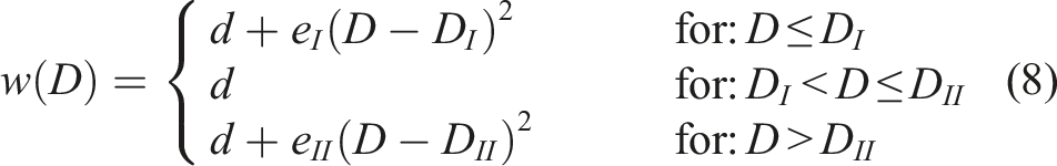
In the formulation (1) to (8), the proposed damage material model involves the elastic constants E i , G ij , and ν ij as well as the failure strains γ ij and – if applicable – γ ijkl as material parameters required anyway for a linear elastic simulation. Additional material parameters due to the damage formulation are the damage evolution exponent n as well as the parameters e I , e II , D I , and D II entering the warping function (8). The damage evolution exponent n is easily determined from the slope of a fatigue S-N curve. The parameters in the warping function derive from the stiffness degradation during a fatigue experiment till failure. Thus, material model requires a minimum number of additional material parameters.
Probabilistic simulation strategy
The effect of manufacturing induced imperfections can be modelled either by defining nonzero initial values D = D0 to the damage variable or by assigning reduced values
In general, the stochastic analysis using random fields requires the analysis of a sufficient number of realizations of the random fields with an individual finite element analysis for each realization together with a stochastic assessment of the entire set of results. In order to avoid the numerical effort of a direct Monte-Carlo analysis, the present study adopts a stochastic analysis based on a pre-defined discretization of the space of the random variables (Beckmann and Hohe 22 ).
For this purpose, consider a system which is described in terms of a set of q random variables ξ(i) with i = 1, …, q. These random variables could for example be the initial values D0(x
p
) or the (reduced) failure strains ɛ
ij
(x
p
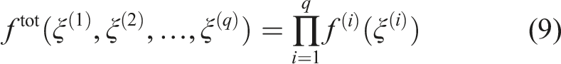
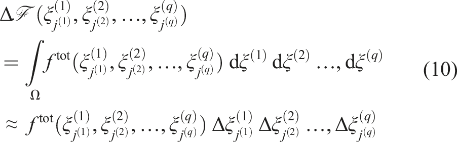
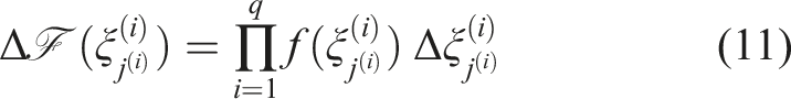
) at each spatial position or any other set of variables defining the effects of the initial imperfection distribution in the pressure vessel. In case of a finite element simulation of the pressure vessel the random variables might be defined individually at each integration point for each finite element in the model. Each of the random variables ξ(i) is provided with an individual probability density distribution f(i)(ξ(i)). As a consequence, the total probability distribution is given by the product
In a numerical analysis, the use of a continuous distribution of the random variables defining the simulation model – here the material properties of a finite element model for the pressure vessel – is problematic. Therefore, the space of the random variables ξ(i) is discretized by considering a sufficient number of discrete values Discretization of the space of the random variables for the special case of q = 2.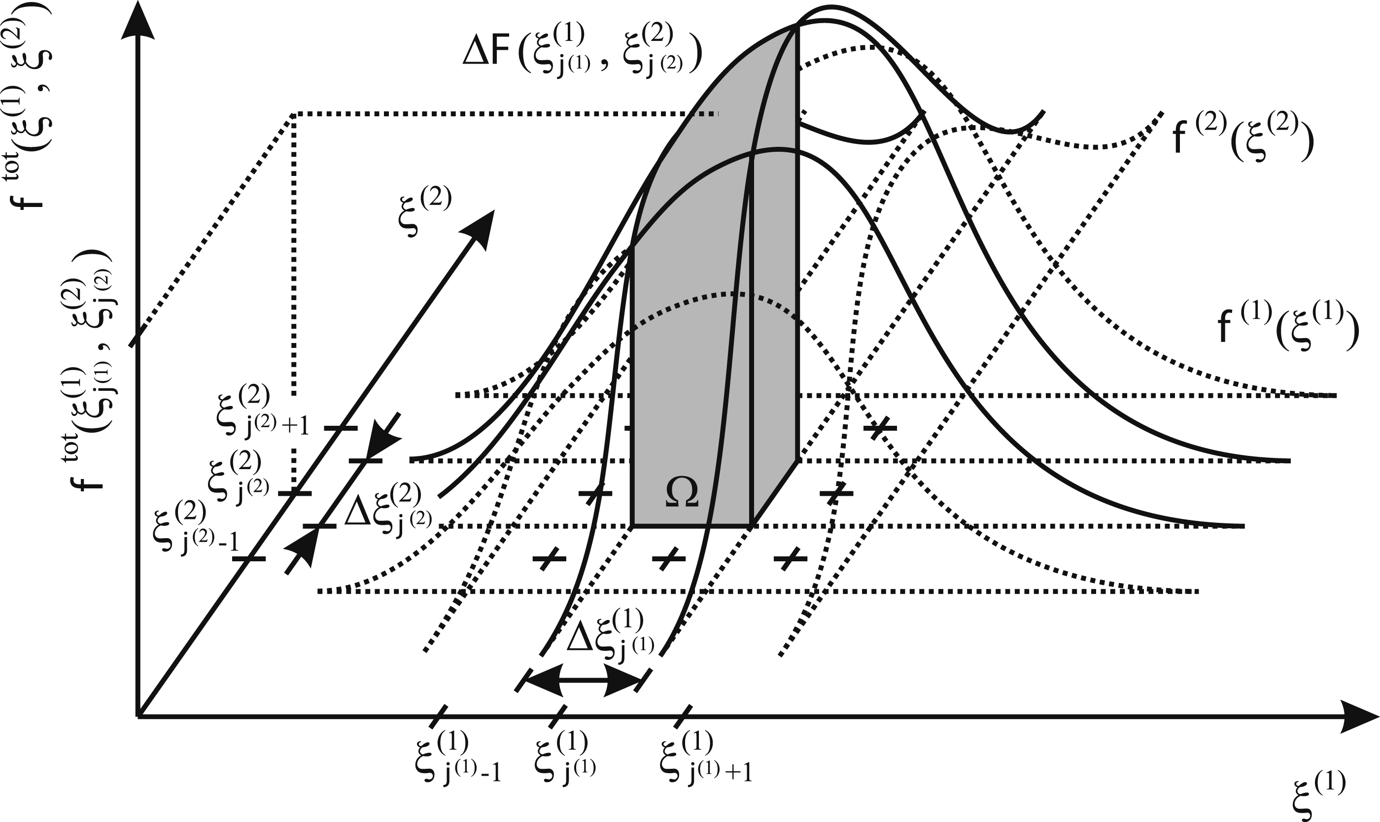
In the general (q-dimensional) discretized space of the random variables ξ(i) with i = 1, …, q, the individual probability for occurrence of the discrete combination
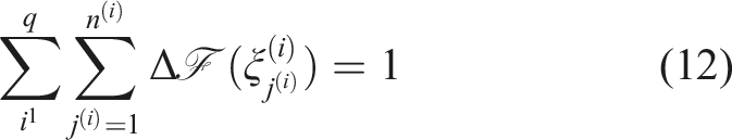
Naturally, the result
Thus, the strategy for the probabilistic vessel assessment requires the definition of appropriate random variables ξ(i) describing the inherent imperfection situation and the identification of their probability density distributions f(i)(xi(i)) based on experimental observations of the distribution of the inherent manufacturing induced imperfections. Subsequently, the space of the random variables is discretized according to Figure 6. For each set
For this purpose, the respective results
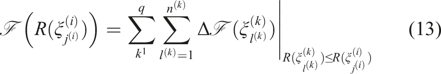
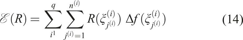
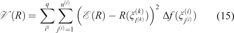
Alternatively to the direct assessment in terms of the probability distributions (13), a simplified stochastic assessment can be performed in terms of basic stochastic parameters such as

Finite element analysis and random variables
For the structural analysis, the reference pressure vessel is discretized by standard displacement based three-dimensional 8-node finite elements with a tri-linear displacement interpolation. Through the thickness, the pressure vessel shell is discretized such that the element boundaries coincide with the boundaries of the individual [±α]-plies. Therefore, the material response is modelled on the ply effective level defined by the fibre angle α of the respective plies using the damage mechanics material model defined by equations (1) to (8). The liner is discarded in the finite element model since, due to the low stiffness of its polyamide six material compared to the CFRP overwrap and the essentially similar strains due the bond between liner and overwrap, the liner cannot substantially contribute to the overall load carrying capacity of the pressure vessel shell. The finite element model consisting of 580,167 nodes and 426,520 elements is presented in Figure 7. The model is provided with statically determinate displacement boundary conditions in the range of the boss section in order to prevent rigid body motions, however, not inducing the development of any artificial local stresses and strains. The model is loaded by an internal pressure, induced through a prescribed normal stress on the internal surface of the vessel. For proportional burst analyses, the internal pressure is increased proportionally until failure whereas a harmonically varying internal pressure is applied for fatigue analyses. The discretization had been validated in preliminary parametric studies using different discretization densities. Finite element model and random field approach for probabilistic integrity analysis.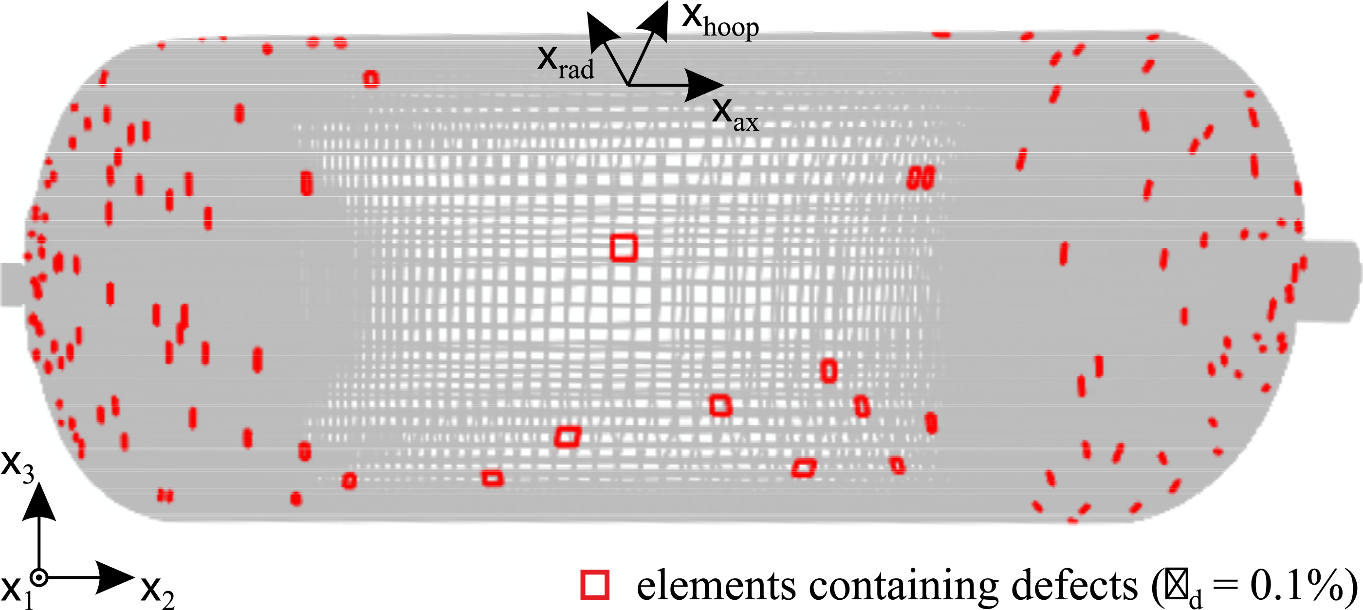
In the probabilistic analyses, two sets of random variables are considered. The primary random variables describe geometry, size, and distribution of the inherent manufacturing induced imperfections through the pressure vessel shell. Secondary random variables are employed to describe the effects of the manufacturing induced imperfections on the strength of the material forming the pressure vessel shell. Both sets of random variables are interrelated by deterministic, although not explicitly defined correlations, i.e., the secondary random variables are functions of their primary counterparts rather than being true independent random variables. The qualitative and quantitative interrelation between the primary and secondary random variables, that is between the uncertain quantities themselves and the parameters describing their effects on the mechanical performance of the material are established numerically by the multiscale analysis.
As secondary random variables, the failure strains γ11, γ22, γ33, γ23, γ13, and γ12 in equation (4) are considered. The coupling components γ1122, γ2233, and γ3311 therein are neglected. In the finite element analyses, the primary random variables form random fields γ ij (x k ), describing the effect of inherent imperfections depending on the spatial position within the vessel shell. The interrelation of the failure strains γ ij and the primary random variables is determined numerically by means of a multiscale analysis.
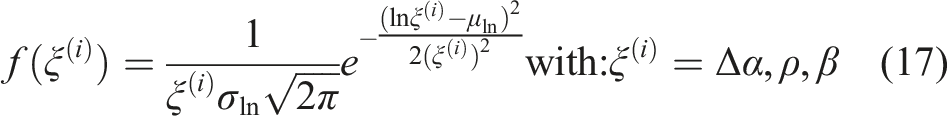
In the present case, worm pores as well as a fibre misalignment were identified as the most relevant manufacturing induced imperfections (Figure 2). Based on this observation, the deviation Δα of the fibre angles from their nominal values, the average volume fraction ρ of the finite elements containing worm pores, and a parameter describing the distribution of the worm pores across the shell thickness are chosen as primary random variables. For the variation of the imperfection volume fraction through the vessel shell thickness and thus its deviation from the average imperfection ρ the tomographic investigations revealed a preference towards a location in the outer plies. The effect is caused by the pressure applied to the inner plies during winding of the outer plies, compressing initial worm pores in the inner plies and thereby leading to a partial closure of the worm pores in the inner plies. Assuming that the total pressure applied to the inner plies increases proportionally with the number of plies wound on top of them, a linear distribution of the worm pores through the thickness is assumed. The linear distribution is characterized by the ratio β of the imperfection density ρout on the outer shell surface to the imperfection density ρin on the inner shell surface.
The variables Δα, ρ, and β form the first three random variables ξ(i), i = 1, 2, 3 in the probabilistic simulation strategy defined by equations (9)–(16). For the finite element analysis, imperfections are distributed randomly across the finite element model of the pressure vessel such that the prescribed discrete values of the random variables ρ and β are attained. An example for the spatial distribution of the finite elements containing imperfections, that is, a realization of the random field, is presented in Figure 7.
For each set of discrete values for the random variables Δα, ρ, and β, a total of 10 generations of the random field are used whose identifier r with r = 1, …, 10 forms a fourth random variable ξ(4). A total of six classes of worm pores with different length and diameter is considered. Their identifier s with s = 1, …, 6 finally provides the fifth random variable ξ(5).
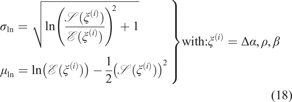
All random variables are provided with corresponding probability density distributions. For the first to third random variable Δα, ρ, and β, respectively, logarithmic normal distributions
Effects of manufacturing induced imperfections
Within the proposed scheme for probabilistic integrity assessment, the effect of fibre angle variations Δα are considered directly by using the material data for [±(α + Δα)]-plies instead of the data for [±α]-plies.
For the worm pores, the secondary random variables γ ij describing their effects on the effective strength on the level of the [±α]-plies need to expressed in terms of the primary random variables that is, the pore geometry. The interrelation between the primary and secondary random variables is established numerically using a multiscale analysis of stochastic volume elements (SVE) containing imperfections with preselected geometries.
As sketched in Figure 8 the stochastic volume element consist of parallelepiped-shaped cut-outs of the microstructure with a square base of 1 mm × 1 mm in the laminate plane stretching across a [+α]- and a [−α]-ply each with a total thickness of 0.24 mm in the transverse (x3-) direction. The [+α]-ply is assumed to contain a worm pore of length l and diameter d oriented in its local fibre direction and located centrally at the interface between the two plies. For modelling purposes, the fibre orientation of the [+α]-ply and thus the worm pore is chosen such that it coincides with one of the SVE edge directions. Hence, the coordinate system Voxel-based stochastic volume element analysis for determination of reduced strains to failure in presence of imperfections.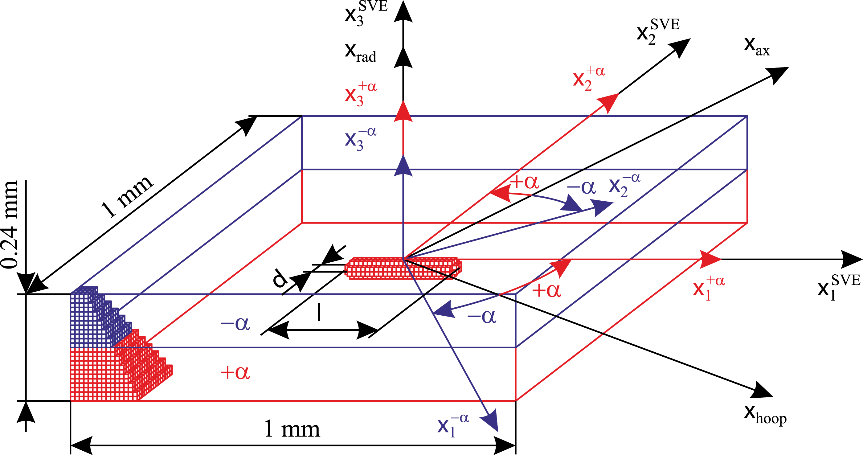
The stochastic volume elements are meshed in a voxel-based approach by 100 × 100 × 24 cuboidal finite elements with 10 µm edge length. Standard 8-node displacement based elements with tri-linear shape functions are employed. The material response of all finite elements is described by Hooke’s law assuming transversal isotropy with respect to the respective fibre direction in the
In order to determine the global material parameters for the [±α] plies together with the failure strains γ
ij
related to the (xhoop, xax, xrad) coordinate system, the stochastic volume elements are loaded by uniaxial applied macroscopic strains
Results
Material parameters
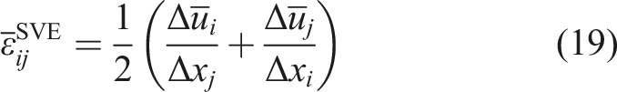
The results of the quasi-static tensile experiments on coupon level are presented in Figure 9, concerning loading within and perpendicular to the fibre direction of the unidirectionally fibre reinforced material – [0°] and [90°], respectively – as well as the [±45°]-laminates. For the unidirectionally fibre reinforced material, an almost linear response is observed in both the 0°- and 90°-directions. Failure occurs in a sudden brittle mode without relevant preceding nonlinearities in the stress-strain response. However, all 0°-specimens are found to fail by a mixed-mode sub-tab failure rather than by fibre fracture in their gauge sections. This effect is due to the (although small) residual curvature of the fibres towards the specimen ends, enabling a failure in a shear mode along the slightly curved inter-fibre planes. Thus, the resulting failure stresses and strains provide highly over-conservative lower limits to the tensile strengths of the material. An alternative could be to machine plane specimens from filament wound precursors with plane sections. However, this method in general has the implication of the development of non-negligible residual stresses and thus specimen distortion as well as – due to vanishing filament pressure onto the winding core in its plane sections – deviations of the fiber volume fraction from its desired value (Hohe et al.
32
). The use of NOL ring experiments or similar experiments using circular specimens as the other alternative is also problematic since here the strain measurement might be affected by friction in between specimen and the split disk type loading device. Therefore, these parameters are substituted with literature values for a similar material (Hohe et al.
32
) in the subsequent numerical computations. In this context, the failure strain was chosen such that the failure stress measured in this study,
32
that is in average Results of coupon experiments under quasi-static loading conditions.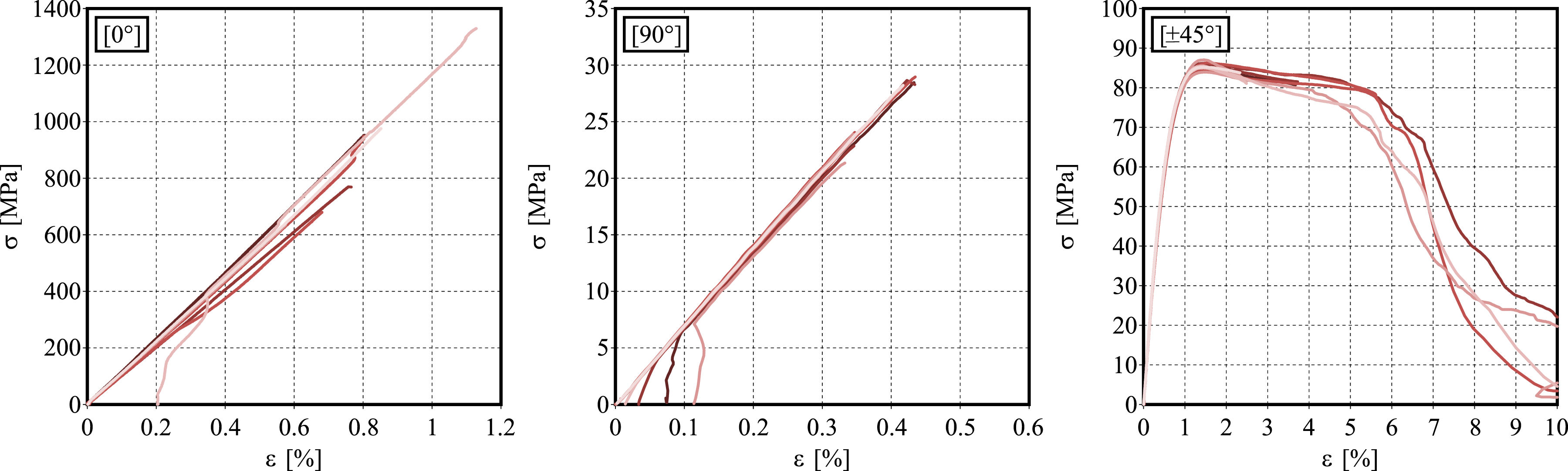
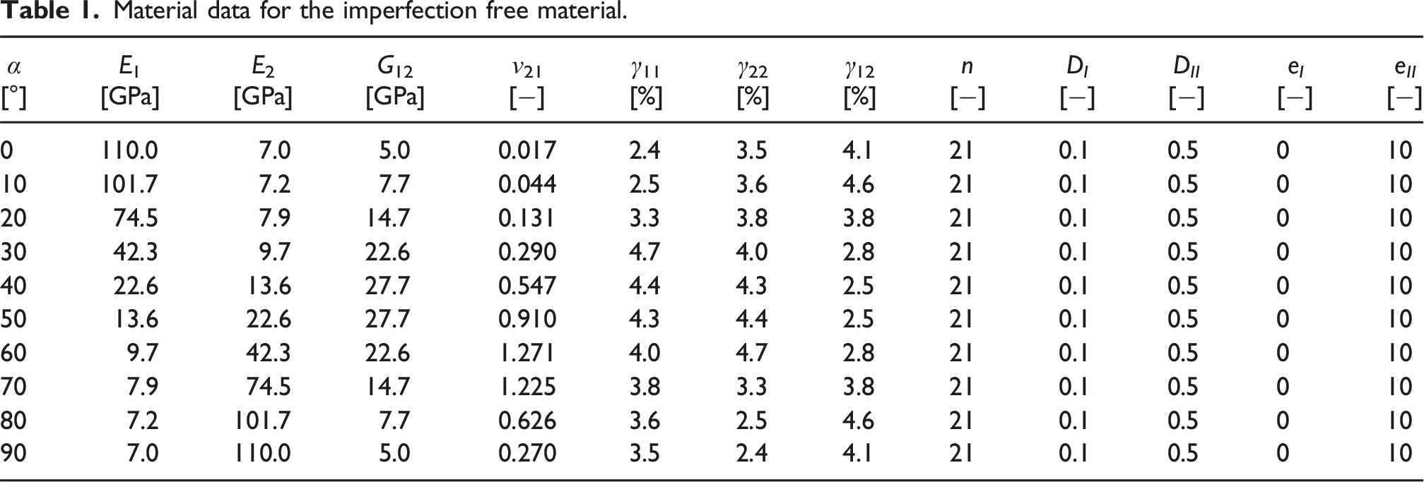
Material data for the imperfection free material.
The results of the fatigue experiments on 90°-specimens at a load ratio of R = 0.1 are presented in Figure 10. The experimental results are approximated by a linear regression line in the double logarithmic representation as a S-N curve together with the 5%- and 95%-quantiles assuming a Gaussian distribution with respect to S-N curve. For information, the static results are added to Figure 10, concerted into “pseudo-load ranges” for R = 0.1 (i.e., 90% of the static strength). In line with previous studies on fatigue of unidirectionally reinforced carbon-epoxy material (e.g., Hohe et al.
32
), a S-N curve with rather low slope is obtained. In the static limit for Nf → 1, the S-N curve approaches the (converted) static strength. Throughout the considered failure cycle range, a limited scatter is observed. From the experimental results, the damage exponent n is determined by a numerical simulation of the fatigue experiments in conjunction with reverse engineering. For simplicity, the parameters D
i
, D
II
, e
I
, and e
II
describing the “warping” of the damage evolution equation (7) are kept constant, in line with the findings in previous studies using similar models (Hohe et al.,
32
Abdul Hamid et al.
28
). Using the fitted parameters, the numerical predictions are found in a perfect agreement with the experimental observation. Notice that the damage law proposed by Abdul Hamid et al.
28
perfectly reproduces the characteristics of the S-N curve as a straight line in the double logarithmic representation. Results of coupon experiments under cyclic (fatigue) loading conditions.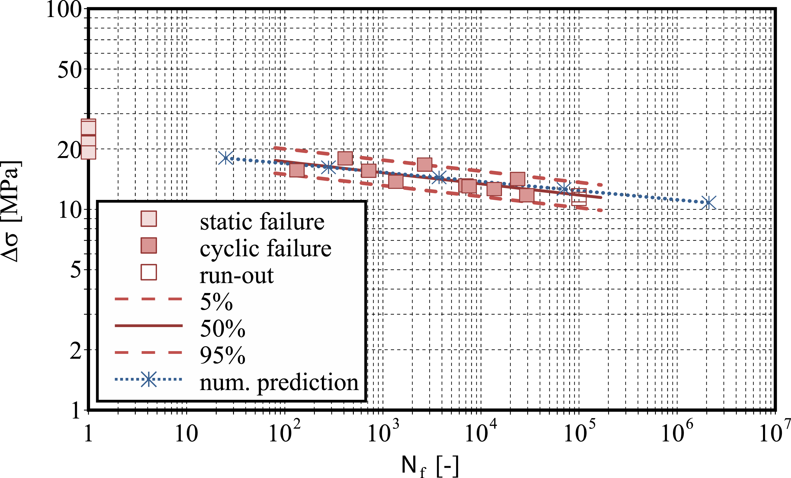
Using the results for the unidirectionally fibre reinforced material coinciding with the parameters of the [±α]-laminate for α = 0°, the parameters for other fibre angles are determined numerically by means of the homogenization procedure under the assumption of an imperfection free volume element. The results are compiled in Table 1.
Subsequently, the effects of imperfections with different sizes and shapes are analysed for different fibre angles to provide the input data base for the stochastic finite element analysis of the pressure vessel. For this purpose, the failure strains γ
ij
are determined for volume elements according to Figure 8 with different winding angles α, containing worm pores with different predefined lengths and diameters. For each volume element, the individual reduced in-plane failure strains γ11, γ22, and γ12 are determined as described above. The results are presented in Figure 11. For reasons of a more comprehensive presentation, a representation as a function of the resulting imperfection volume fraction ρdef as a single variable rather than the pore length and diameter as the two direct variables is chosen. It is observed that in general, increasing imperfection volume fractions result in decreasing failure strains. A distinct decrease in the local strength is observed especially in the initial range of ρdef in the transition from the imperfection-free state at ρdef = 0 to the situation in presence of small imperfections at ρdef > 0. Increasing defect sizes where both diameter and length of the worm pores are increased, indicated by increasing imperfection volume fractions ρdef degrade the local material strength in terms of the failure strains γ
ij
further. However, no rigorously monotonic effect is obtained, since worm pores with different size and shape are considered in a combined manner in single diagrams. Stochastic failure analysis on volume element level.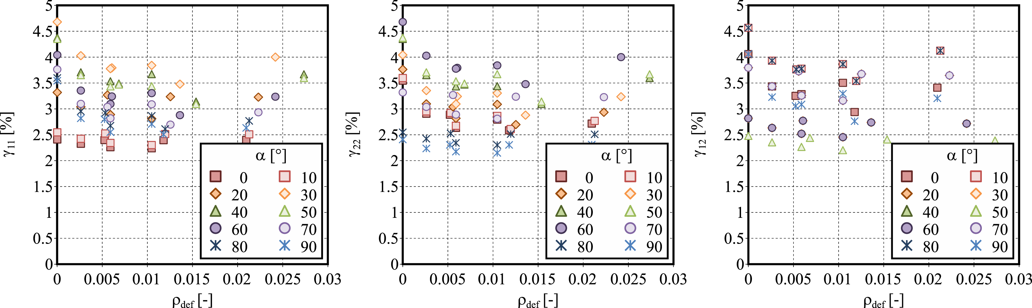
Burst analysis
On two reference vessels, physical burst experiments were performed. The two vessels failed at burst pressures of 158.4 bar and 185.2 bar, respectively. In both cases, failure was initiated at the intersection of cylindrical section and dome. The failure mode can be observed in Figure 4, showing one of the reference vessels prior to and after the instrumented burst test. An extract of the local strain measurements during the experiments is presented in Figure 12, showing the axial and hoop strains measured on the dome and cylindrical sections approximately 10 mm apart from their intersection, i.e., close to the section triggering burst of the vessels. Strain data were acquired on both ends of each of the two vessels, resulting in a total of four measurements at nominally identical positions. Since the strains on the vessel surfaces partially exceeded the failure strain of the adhesive bond of the resistance strain gauges no strain data is available for part of the measurement positions at higher pressures when approaching the burst events. Results of burst experiments.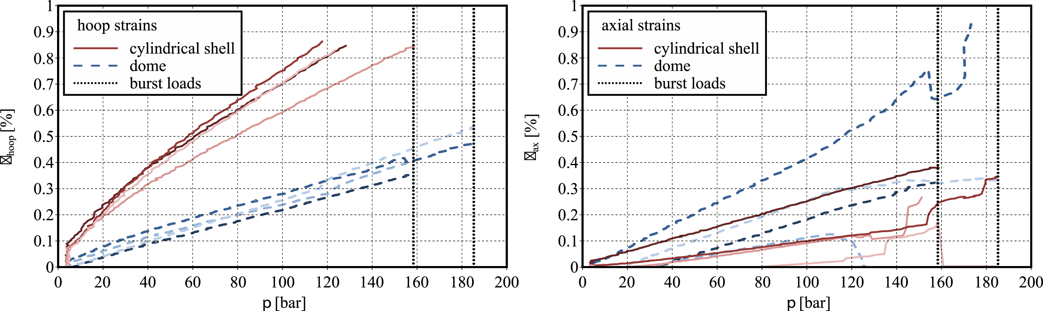
Smooth strain-pressure curves are obtained for the hoop strains on both, cylinder and domes. In both cases, a limited but not negligible scatter between the individual measurements is observed, indicating uncertainties in the material response. For the axial strains, more distinct variations between the individual measurements are observed for both positions, indicating possible strain localizations and thus development of damaged zones. When approaching the respective burst loads, a development of distinct, non-monotonous variations in the strain versus pressure curves is observed. This observation indicates the development of first, locally restricted failure events prior to the final catastrophic burst event. The different characteristics of the strain versus pressure curves for the hoop and axial strains respectively also indicate a burst initiation in the axial direction rather than a circumferential tear failure. This indication is in line with the failure mode observed in Figure 4, where one of the domes is found to be blasted off in the axial direction.
The results of the stochastic simulations of the burst experiments are presented in Figure 13. In the first subfigure on the left hand side, the development of the damage variable D with increasing internal pressure is presented for the respective finite element finally triggering burst. The results are presented for all discrete sets of the random variables considered in the stochastic analysis. In addition, results obtained on a finite element model without any imperfection are presented, forming an upper bound to the simulation of the defective vessels. In all cases, a slow-growing damage development is observed during most of the load history, turning into a rapid increase when the respective failure load level is approached. Due to the brittle material response and the force-driven loading conditions, the failure of the first element results in sudden catastrophic failure of the entire vessel. The predicted burst loads are in the range of the two burst experiments in Figure 12. Simulation of burst experiments.
Concerning the spatial distribution over the pressure vessel shell, the damage development is found to localize in narrow zones along the intersections of the cylindrical shell and the domes of the pressure vessel due to the stress concentration in this region induced by the development of bending stresses on top of the membrane stresses present everywhere in the vessel shell. An example at the instant prior to burst is presented in the central subfigure of Figure 13. The exact location of the predicted burst initiation is evaluated in detail in the subfigure on the right hand side where the predicted burst pressure is plotted as a function of the axial position of the predicted burst location. The predicted burst locations are found in the vicinity of both cylinder-dome intersections at xax = ±289 mm. In most cases, burst is predicted to be initiated in the helical layer or the outer hoop layer whereas failure initiation at locations in the inner hoop layer is predicted only in a few cases. Whereas the failure spots in the hoop layers are essentially located in the cylindrical shell (since only the cylindrical shell is provided with hoop winding), the vast majority of the failure spots predicted in the helical layer is located in the domes. For lower predicted burst loads, the predicted failure position is in all cases located rather close to the cylinder-dome intersection. For larger predicted burst loads and thus larger stress and strain levels in the shell, even local imperfections located farther from the intersection at xax = ±289 mm might trigger failure. The more probable failure locations farther from the intersections result in a widening of the scatter band for the failure locations with increasing predicted burst pressure.
The results for the considered discrete sets of the random variables as presented in Figure 13 serve as the raw data base for the stochastic evaluation using the discretizing sampling procedure. For this purpose, the three random variables Δα, β, and ρ are provided with logarithmic normal distributions in terms of the expectation values Parametric studies – burst probability distribution for different imperfection probability distributions.
In all cases, the green solid lines indicate the reference case. For the reference case the median burst pressure is
In a final analysis, a case study considering the fatigue failure of the pressure vessel is performed. The results are evaluated in terms of structural S-N-curves. In this context, the cases of the imperfection-free vessel as the upper bound and the case with the minimum static burst pressure prediction as the lower limit are considered. In the same manner as under proportional loading, these two limit cases provide an envelope to the different imperfection states considered. The results are presented in Figure 15. Case study – envelope of the pressure vessel fatigue strength.
As for the analysis on material level (see Figure 10), the resulting S-N-curves form straight lines in the double logarithmic representation. Identical slopes are obtained in the fatigue analyses for the different imperfection states considered. This effect is caused by the basic assumptions of the damage model adopted here, together with the weakest-link theory as it is common for failure analysis of components consisting of brittle materials loaded in force-driven modes such as the internal pressure load considered here. The underlying damage theory of the adopted damage model (Abdul Hamid et al. 28 ) assumes that the approach of the strain state ɛ ij towards the static failure envelope defined by Φ = 0 according to equations (3) and (4) drives the development of damage, irrespectively of the loading history. Thus, in accordance with the experimental observations on specimen level, static failure appears as an extreme case of cyclic failure in a single loading cycle, provided that the upper stress limit is considered. Further, the power-law type damage evolution equation (7) deriving from the assumption of microplasticity driven damage evolution (Abdul Hamid et al. 28 ) essentially results in a straight S-N-curve in the double logarithmic representation where the parameter n – although not being the slope – is directly related to the slope of the material’s S-N-curve. Since the considered pressure vessel, consisting of an elastic, brittle material, is loaded in a force (here internal pressure) driven mode, failure of the first material point essentially triggers failure of the entire component due to the immediate overloading of neighbouring material points due to the essential re-distribution of stresses from the initially failed material point. Consequently, the component essentially exhibits the same cyclic failure characteristics as the material in consists of. Since the presence of local imperfections result in a shift in the failure strains γ ij , the presence of imperfections shifts the S-N-curve in total. This observation indicates that the same burst pressure distributions obtained under quasi-static, proportional loading, that is, in the limit case of a fatigue loading history consisting of a single load cycle, will be obtained also for all other fatigue life cases as well.
Conclusions
The present study has been concerned with numerical methods for the prediction of uncertainties in the burst pressure of filament wound CFRP pressure vessels. Uncertainties in the burst pressure are induced by stochastically distributed manufacturing imperfections. Both, quasi-static proportional loading as well as cyclic fatigue loading were considered.
The numerical scheme is based on a time domain damage mechanics material model for CFRP materials capable for both, static and fatigue loading conditions. The model utilizes a Tsai-Hill failure envelope in strain space, assuming the approach of a strain state point towards the failure envelope to drive the damage evolution. Based on the assumptions that the development of material damage is caused by microplastic deformation below the macroscopic yield limit and that the microplastic deformation can be estimated from a Ramberg-Osgood type approach, an incremental power law type damage evolution equation is obtained. For the stochastic analysis, a sampling procedure utilizing a pre-defined discretization of the space of the random variables is employed.
In an application to an experimental data base on coupon level, the utilized damage models is found to provide accurate predictions under both quasi-static and cyclic loading conditions. Especially, the characteristic of the Wöhler type S-N-curve as a straight line in the double logarithmic representation is predicted exactly. The application of the probabilistic scheme to instrumented burst experiments on two reference pressure vessels is found to provide a good approximation of both the range and the scatter band width of the burst pressure probability distribution. Nevertheless, it should be pointed out that the uncertainty in the experimental results consists of both, aleatoric, that is true physical uncertainties and epistemic uncertainties caused by measurement or model inaccuracies. Although the strain in the instrumented burst tests were obtained by means of resistance strain gauges as the in general most accurate strain measurement devices, the involvement of epistemic uncertainties in the measured scatter band cannot be completely excluded.
In a parametric study concerning the uncertainty propagation from the uncertainties in the random variables as the input to the uncertain system onto the uncertainty of the burst pressure as the system response shows distinct effects of the uncertainty in the micro imperfection density whereas the uncertainties in the uncertainty distributions of the imperfection locations through the shell thickness and the fibre misalignments are found to be of minor importance.
The findings of the present study are based on the observation of worm pores and fibre misalignments being the most important imperfections for filament wound material as it was observed for the reference material investigated here. Depending on the manufacturing process other types of imperfections such as for example fibre agglomerations (Fast et al., 8 Gommer et al. 9 ), pores (Huang and Talreja 10 ), incomplete infiltrations (Baranger et al. 11 ) or others might be relevant for other components or composite material types. In these cases, the present approach can easily expanded to cover these imperfection types as well.
Footnotes
Acknowledgements
The authors are fully responsible for the contents of the publication. The financial support is gratefully acknowledged.
Funding
The author(s) disclosed receipt of the following financial support for the research, authorship, and/or publication of this article: The present work has been funded by the German Federal Department of Education and Science (BMBF) under Grant No. 03ZZ0743D as part of the project HYPOS-H2HD.
Declaration of conflicting interests
The author(s) declared no potential conflicts of interest with respect to the research, authorship, and/or publication of this article.
Data Availability Statement
The data of the present contribution forms part of an ongoing study and cannot be shared at this time.