
Abstract
A comprehensive study on the impact behaviour of patch repaired composites with different impact locations has been performed. Specimens were impacted at three different locations relative to the patch repair, recreating different impact scenarios that occur in service. For the first time, high-speed digital image correlation was used to reveal impact behaviour of patch repaired composites, including the identification of failure modes. This was further supported through the use of post-impact ultrasonic C-scans. Patch repaired composites were found to improve impact damage tolerance, with a 40% reduction in damage area when impacts occurred directly on the patches. However more failure modes were observed when impacts were close to the repair location, this complexity decreased as impact location was positioned further away from the repair patch. Residual strength for repaired specimens was found to be greater than the pristine specimens, regardless of their impact locations and repair methods, underlining the effectiveness of repair patches. This study contributes to a deeper understanding of how repaired structures respond to impact loading, suggesting that patch repair approaches may be overly conservative.
Introduction
Aircraft structures are likely to incur damage in service, necessitating repair or replacement. Repair of damaged components is a preferred practice in the aviation industry to restore initial structural performance of partially damaged structures that are suspected to have low residual strength. 1 This is because it is considered more economically advantageous to repair components than replace them, whilst still maintaining structural capabilities under different types of loading. 2 This approach balances cost efficiency with the need to ensure safe operation of repaired aircraft. Furthermore, repair approaches reduce the scrap rate of damaged composite components and thus is environmentally beneficial given most composite components are currently sent to landfill. 3 However, repair processes can increase structural complexity in components, potentially leading to different structural behaviour. They also involve applying additional stresses on the material such as heat and pressure during the repair process. Therefore, several factors must be considered during the repair of components, including stiffness, strength, stability, operational temperature, repair durability and aerodynamic smoothness. 4
The two most common bonded repair methods for composite structures used in industry are: patch repairs5–8 and scarf repairs.5,9 In both methods, an adhesive layer acts to transfer load from the original structure to new material in order to relieve stress. Scarf repairs involve removing a tapered area of the structure, resulting in a sloped conical surface for repairs. They result in lower stress concentrations and are more aerodynamically favourable compared to other repair methods. 10 However, scarf repairs are far more complex to implement, require removal of substantial amounts of undamaged material, and require intensive skilled labour. In contrast, patch repairs only require removal of damaged regions, resulting in an open hole. A pre-moulded patch, larger than the hole is then adhered over it, known as single patch repair or if on both sides of the hole, is known as a double patch repair. Hence, patch repairs are more favourable since they are less complex, leading to better cost-efficiency whilst still improving component durability. 11 Both repair methods have different damage behaviour due to their distinct repair performance and stress concentrations near the repaired regions. For example, Mahdi et al. 5 found scarf repairs have weaker compressive strength than patch repairs, achieving 90% and 100% of the undamaged strength respectively. 5 They also concluded both repair methods had higher bending stiffness compared to pristine specimens with all failures occurring outside the repaired region, showing the effectiveness of the repair. These prior studies have only focused on simple experimental evaluations, limited to bending or compressive strength measurements.
Impact of composites remains a highly researched topic due to concerns about its effect on structural integrity.12–14 Repaired composite structures are still susceptible to impact15–17 during their service life. However, experimental studies on the impact response of repaired composites remain limited in comparison to those on unrepaired composites.2,10,18–21 This is possibly due to the complexities involved in manufacturing repaired specimens, hence more experimental studies are required to improve the knowledge of repaired composites as they were being impacted. Rezasefat et al. 22 found that the presence of an open hole significantly changed the stress distribution during impact in composites based on simulation results, resulting in a larger predicted delamination area. Such behaviour was also reported in another study, which identified the effect of distance between impact location and hole position. 18 Liu and Yan 9 found that impacting near adhesively bonded regions resulted in more severe damage. It was found that cracks were initiated at the adhesive which then propagated within plies, resulting in larger delaminations. This was also found in some studies where composites were impacted near the repair patch boundaries, significantly affecting composite damage behaviour.2,19 In these studies, impact energies, damage areas and compressive strength after impact were analysed to identify damage behaviour of the repaired specimens. This shows the importance of understanding the effect of impact location corresponding to the repaired regions to ensure composite structures can operate safely. However, none of these studies have performed detailed identification of damage initiation and propagation during impacts due to the complexity of the experiments. Impacts are fast events that require high-speed cameras to capture the entire impact process in order to identify the occurrence of different failure modes. This means impact behaviour of repaired composites, particularly damage mechanisms near the repair, remains poorly understood.
The parameters used when performing patch repairs can influence a structure’s post-repair performance, including: adhesive thickness, 23 patch thickness, 24 stacking sequences, 10 shape, 25 and size of the repair patches. 26 Therefore, previous studies have only identified damage tolerance and residual strength of repaired composites with different parameters, aiming to optimize the dimensions of repair patches.23–29 Tie et al. 26 concluded a circular patch with a radius 2 to 2.5 times that of the covered hole is the optimal size for repair patches. As this design resulted in a better impact resistance when comparing absorbed energy for repaired and pristine specimens. Another study has investigated the contribution of patch thickness and adhesive thickness to the effectiveness of repaired composites. 23 The study found that increasing adhesive thickness had negative effects, and that ideal patch thickness was around 40% of the parent laminates thickness. This was supported by Gong et al., 24 who suggested a thinner patch can actually result in a stronger repaired structure.
This study explores both single and double-sided repair patches on carbon-fibre composites specimens at three different distances between repair patches and impact locations. The repair patches were located at 10 mm, 25 mm and 40 mm from the impact locations. This means the specimens were impacted directly on the patch, beside the patch, and away from the patch respectively. Studying the effect of distance between repair patches and impact locations is crucial as it is expected to influence damage behaviour during impact. Most previous studies on impact of repaired composites have only impacted directly on the patch, resulting in a lack of understanding of composite impact behaviour when they are impacted at other locations. Therefore, experiments must be carried out to further understand the effect of repairs as the impact locations are varied. This study is also the first to use a high-speed DIC system to observe damage initiation and propagation as the distance between patch repair and impact location is varied. Unlike prior studies limited to standard strength characterization, this study for the first time integrates impact testing of repaired specimens with high-speed digital image correlation, allowing an in-depth analysis of the effectiveness of repair patches when impacted at different locations. Finally, compression after impact tests were performed to identify residual strength of the specimens and understand how repair patches affect damage morphology when loaded to failure in compression. This presented work offers a comprehensive investigation that addresses impact behaviour of repaired composites under realistic conditions, which has not been reported in any previous studies.
Methodology
Specimen preparation
Cross-ply carbon-fibre composite laminates were first prepared using unidirectional prepreg (RP507UT210, PRF, UK) where the moduli of elasticity in the longitudinal and traverse directions of the cured prepregs were 129.7 GPa and 7.76 GPa, respectively. These moduli were determined by conducting tensile tests on six unidirectional specimens for each direction, fabricated using the same prepreg and complying with ASTM D638. The laminates had a stacking sequence of [02/902/02/902]s with an uncured nominal thickness of 4 mm. All laminates were cured under 6 bar pressure using a hot-press (APV-2525, Meyer, Germany), complying with the prepreg manufacturer’s recommendations. They were heated to 120°C from room temperature at a ramp rate of 2°C per minute and cured for an hour once at desired temperature. These specimens were then allowed to cool down naturally to room temperature within the hot press before pressure was released. Cured laminates were cut to a size of 150 mm by 100 mm, representing parent laminates in this study. A 15 mm diameter hole was then removed at various locations (10 mm, 25 mm and 40 mm from centre) of the laminates to replicate the removal of damaged material. This was achieved by first creating a 6 mm hole using a carbide crown point drill (29.0080 B, Karnasch, Germany), followed by a 4 mm carbide fibreglass router end mill (11.6003, Karnasch, Germany) to enlarge the hole to 15 mm diameter. This method was used to minimize the chance of delamination, which is a concern during machining of composite materials. 30 All specimens were then assessed using a pulse-echo ultrasound machine (Midas-NDT, UK) to confirm that no delaminations were formed near the hole due to machining.
Repair patches were prepared using the same prepreg and similar stacking sequence to the parent laminates, [0/90/0/90]s, resulting in a nominal thickness of 2 mm. The repair laminates were cured using the same process as the parent laminates. They were then machined into 30 mm diameter round patches using an abrasive waterjet machine (MAXIEM 1530, Omax Corporation, USA). The contact surfaces between both parent laminates and patches were roughened using 60-grit sandpaper and cleaned with acetone. All patches were positioned to ensure that the top surface fibre orientations of both parent laminates and patches remained parallel. Adhesive layers (XPREG XA120 Epoxy Resin Film, Easy Composites, UK) with a nominal thickness of 0.2 mm were placed between parent laminates and repair patches. They were cured using the same curing parameters as the laminates mentioned above, which also complied to the adhesive manufacturer’s recommendations. Two different repair methods were implemented in this study, single patch (where one patch is on the top of the specimen) and double patch repairs (where the patches are on either side). A schematic diagram for both single and double patch repair specimen where the patches are 25 mm from the impact location is shown in Figure 1. In this study, six specimens were prepared for each of the three different repair locations: 10 mm, 25 mm and 40 mm from the impact location. Resulting in a total of 18 repaired specimens. Six pristine specimens were also used where no holes or repair patches were present in order to serve as a benchmark for impact tolerance. Three different distances between repair and impact were used in this study: 10 mm, 25 mm and 40 mm. The three repair locations were chosen based on the following considerations. 10 mm from the impact location was selected as numerous studies have already focused on impacts at the centre of the patch. For the 40 mm from impact location was the maximum permissible offset within the ASTM D7136 support fixture and impact at 25 mm from the impact location is the mid-point between the two limits. Plan and side views of (a) single and (b) double patch repaired specimens, 25 mm away from the impact location marked as red. The dashed line indicates the edge of the open window on which the specimen sat during the impact.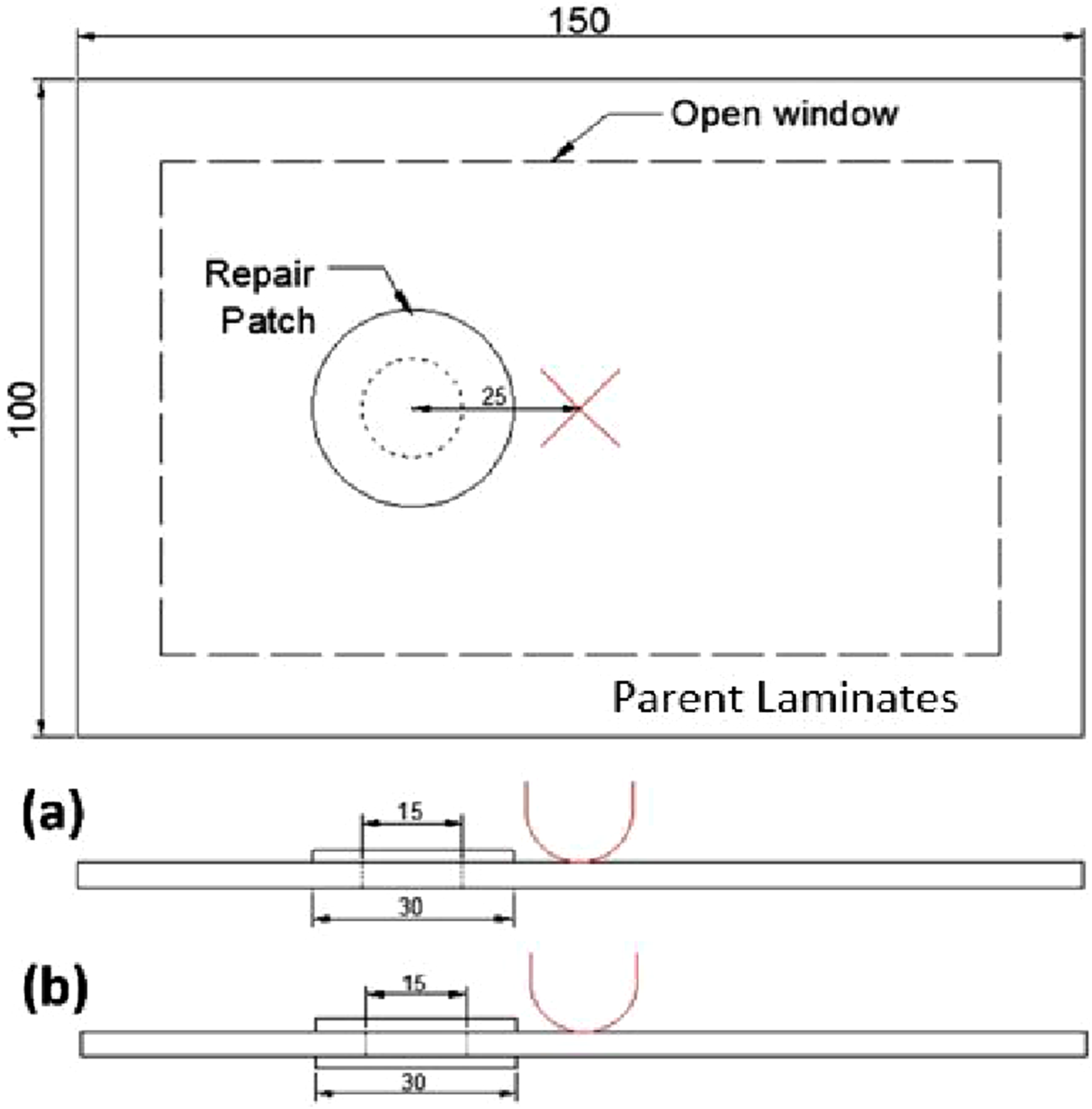
Impact testing with post-impact assessment
Impact testing was carried out using a drop-weight impact machine (CEAST 9340, Instron, Italy), compliant with ASTM D7136. The machine was equipped with a 16 mm hemispherical tup with a mass of 4.215 kg in this study. All specimens were impacted at an energy level of 30 J to ensure comparability. The drop-weight impact machine was measuring load-time data. In order to measure surface strain on the specimens, high-speed DIC cameras (Phantom v711, Vision Research) were recording the bottom surface of the specimens at a frame rate of 10 kHz during the impact. This high frame rate ensured all impact moments were captured, allowing the monitoring of changes in strain fields on the bottom surface of the specimens using the DIC system. The DIC setup consisted of a pair of cameras equipped with 100 mm focal length lenses (Makro Planar 2/100 T*, Carl Zeiss, Germany) and set to an aperture of f8.0. All captured images were processed using Istra4D (Dantec Dynamics, Germany) to calculate displacement data using a facet size of 25 pixels and grid spacing of 10 pixels. All displacement data was smoothed with a grid reduction factor of 2.7 and smoothness factor of 0.1 to obtain strain fields. These parameters were chosen as they were found to give a good balance between spatial resolution and measurement uncertainty of strain fields. 31
Post-impact assessments were then carried out on all specimens to have a better understanding of damage formed in the specimen. Time-of-flight C-scans were performed using a pulse-echo ultrasound machine to identify damage formed in the specimens due to impact. All specimens were scanned with a frequency of 6 MHz and the ultrasonic transducer was moving at a speed of 100 mm/s along a raster pattern grid spacing of 0.2 mm to ensure optimal sensitivity. 31 In addition, microscopy images were captured using a stereoscope microscope (Wild M8, Wild Heerbrugg, Switzerland) to observe damage on the top surface of the specimens. Images were taken near the patches for all specimens as damage formation at these locations is far more complex and can occur near the surface.
Compression after impact
To determine each specimen’s residual strength (i.e. the applied strength at which the impacted specimens failed), compression after impact tests were conducted after they were subjected to 30 J impact. A compression after impact rig complying to ASTM D7137 was used to support the impacted specimens as they were loaded in a 250 kN universal testing machine (6800 Series, Instron, United States). A platen was attached to the load cell and was in contact with the top specimen edge during the tests. All specimens were compressed until a 30% drop from the peak load to avoid complete failure, as described in the ASTM standards. The entire loading process was recorded using a stereoscopic DIC system (Q-400, Dantec Dynamics, Germany), located in front of the testing machine. The standoff distance between the specimens and cameras was 1900 mm to measure three-dimensional displacements. Both cameras (Manta G-505B, Allied Vision Technologies, Germany) had a resolution of 2452 by 2056 pixels and were equipped with a pair of 50 mm lenses (Xenoplan 2.8/50, Schneider, Germany). Both cameras were operating at a frame rate of 5 Hz with an aperture of f8.0 and the distance between both cameras was 540 mm. The specimens were illuminated with a single LED light array (Dantec Dynamics, Denmark) located between the cameras to ensure well-exposed images. The cameras were recording what was the bottom surface of the specimens when they were impacted. Therefore, the same speckle patterns used during the impact tests were used to track surface deformation during the compression tests. The described experiment setup is shown in Figure 2. Captured images were processed using Istra4D (Dantec Dynamics, Germany) with identical parameters as those used for the data from the impact tests. Time-of-flight C-scans were also performed after the tests using the pulse-echo ultrasound machine with identical parameters to those measurements done for specimens after impact. This provided a better understanding of how repair patches affected the final damage morphology. Experimental setup of the compression after impact test with a DIC system located in front of the test machine to record the loading process. The inset shows a close up view of the CAI rig.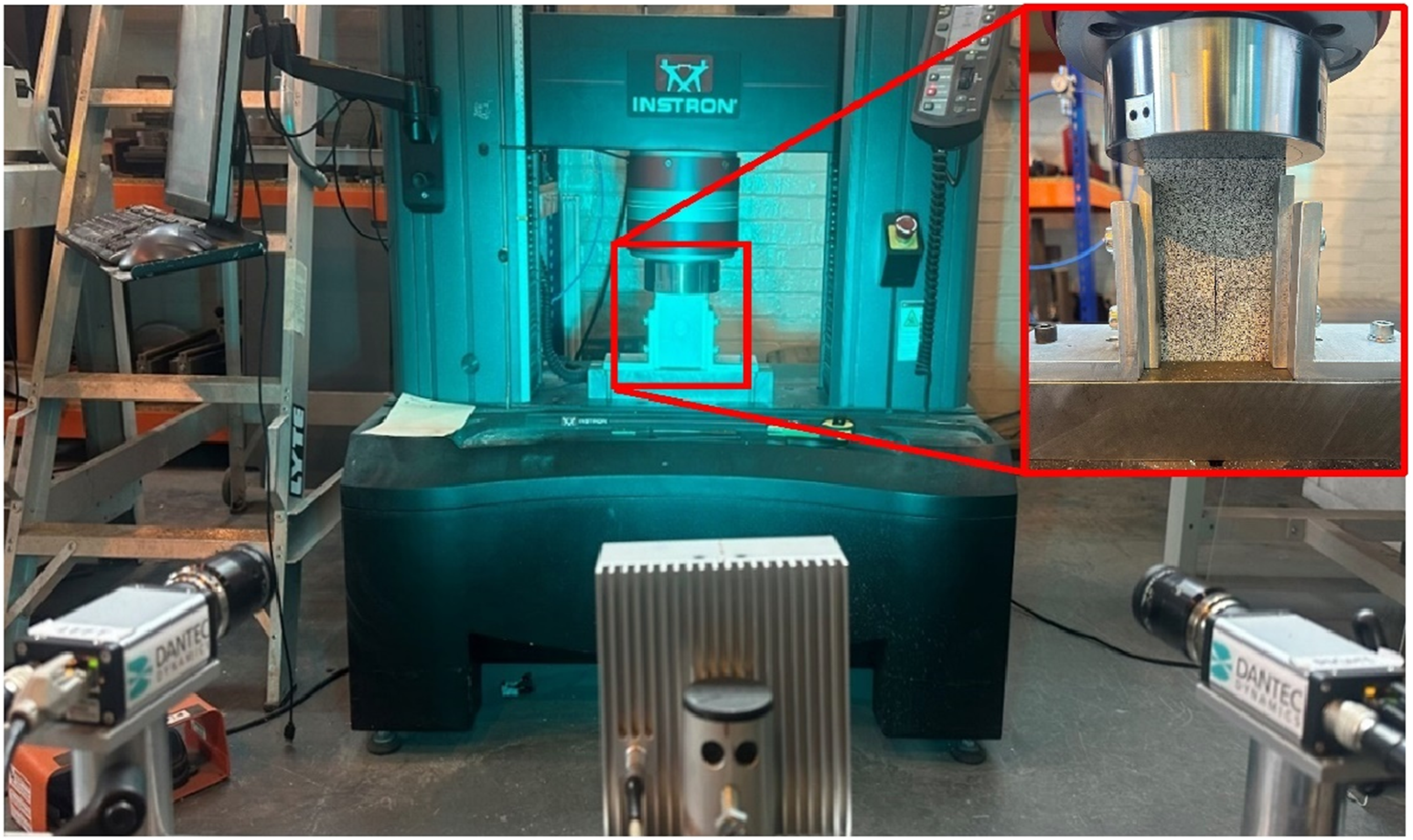
Results
All specimens were impacted at their centre with the patch different distance from the centre. This resulted in impacts directly on the patches, beside the patches and away from the patches respectively. For each location, three specimens had single sided patch repairs and three had double sided patch repairs. The single patch repaired specimens were impacted on the same side as the patch. All repaired specimens were then compared to the pristine specimens. Different experimental approaches such as pulse-echo ultrasound, impact load-time data, and analysis of surface strain fields during the impact were used in this study to gather information about the impact. This detailed information provided a better understanding of the effects on impact behaviour of varied impact locations with different repair methods.
Impact damage behaviour
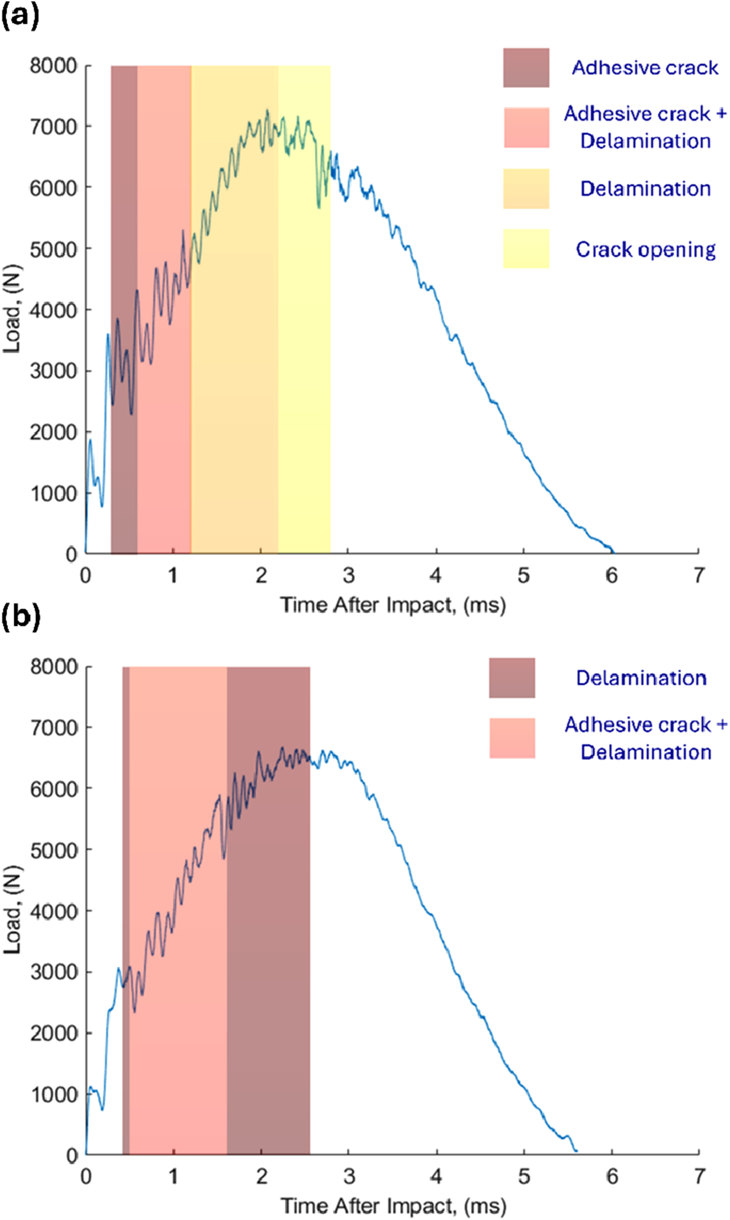
After examining the high-speed images for all specimens, three different failure modes were identified. Figure 3 shows the examples of the different failure modes. These images are from one of the double patch repaired specimens, with the patches located 10 mm away from the impact location. These failure modes were identified manually based on the recordings from the high-speed cameras. Adhesive cracking was the first failure mode found on the top patch at 0.5 ms after the impact began. This type of failure was identified by looking for cracks near the patch region with an example shown at Figure 3(a) and was found to be followed by delamination in the parent laminates. According to the captured images, two types of failure occurred simultaneously between 0.5 ms and 1.2 ms. Delamination was the dominating failure mode out of all since it lasted for 1.5 ms, and was found in all specimens. It was found to result in the largest damage area for all specimens, regardless of their repair methods and location. Delamination was identified by observing the moment when the bottom ply started to buckle during the impact process shown in Figure 3(b). Both adhesive cracking on the top patch and delamination were found in all six specimens with the repair patch located 10 mm from the impact location. One exception was noted where the bottom patch of a specimen had de-bonded. The final failure mode, crack opening, was found towards the end of the impact phase and lasted for 0.7 ms. This was identified by looking for cracks on the parent laminates and tracking their enlargement over time during impact, Figure 3(c). This scenario was only found for the double-sided patch repaired specimens located 10 mm from the impact location but not in any of the single patch repaired specimens. This process was repeated for all specimens and the occurrence of failures were shaded in their corresponding load-time graph. An example is shown in Figure 4(a) for a double patch repaired specimen with the patch located 10 mm from its impact location. This graph shows the entire process, including the impact and bounce-back phase that has lasted a total of 6 ms. The observed failure modes were shaded with different colours in the load-time graph to classify when each mode occurred. The shaded region between 0.5 ms and 1.2 ms indicated two different failure modes, adhesive cracking and delamination, occurred simultaneously. Captured images of three different failure modes: adhesive cracking identified by a red arrow (a), delamination located between both red dashed lines (b) and crack opening identified by a red arrow (c) observed in a double patch repaired specimen. These occurred at 0.4 ms, 2.2 ms and 2.8 ms respectively. Example load-time graphs with different failure modes (shaded) for a specimen with repair patch located 10 mm from its impact location subjected to a 30 J impact (a) and a specimen with a repair patch at 25 mm from impact location with two different failure modes (shaded) occurring during impact (b).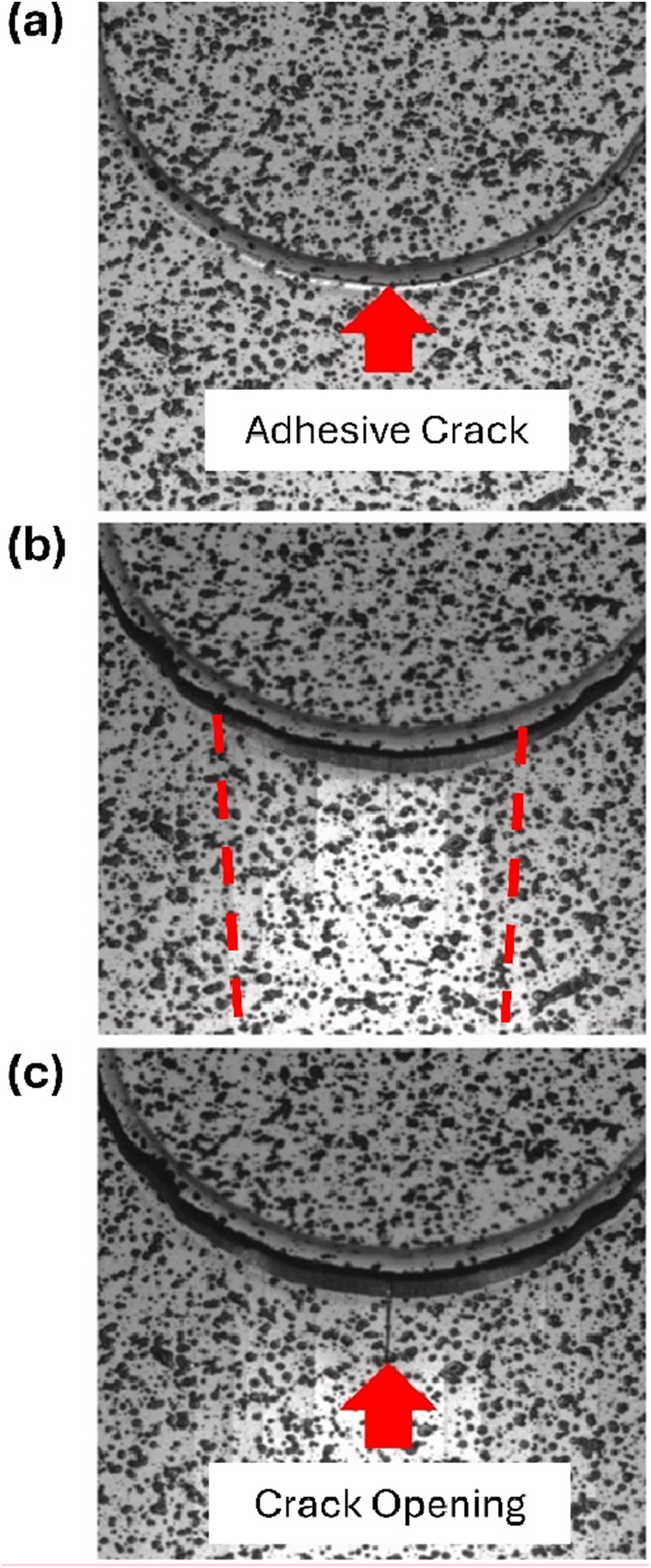
All impacted specimens were then assessed using ultrasonic pulse-echo C-scans to identify their damage location, size and shape after impact. Both patches and parent laminates were scanned separately to confirm the presence of damage in different parts. This approach ensured that the spatial resolution was not compromised along the z-axis. The average damage area in the parent laminates for both single and double patch repair specimens was 1071 mm2 and 1049 mm2 respectively. Figure 5 illustrates two examples with different repair methods where patches were located at y = 10 mm. The first 2 mm of the colour bars indicates damage detected in the patch on the top surface whereas the remaining 4 mm indicates damage found in the parent laminates. The maroon region indicates damage formed in the top patch, which was partially damaged after being subjected to a 30 J impact, shown in Figure 5. This was found for all specimens with repair patches at 10 mm from the impact location, regardless of their repair methods. However, differences in damage morphology were identified in the parent laminates for different repair methods. Two damage strips were found near the bottom surface in the negative y-direction for specimens with a single patch repair, see Figure 5(a). These are shown in yellow indicating they are the bottom most ply interface of the specimen. This behaviour was consistent across all single patch repair specimens where the impact was on the patch. For double patch repair specimens, delaminations were found on the other side of the patch, located in the positive y-direction based on Figure 5(b). This behaviour was confirmed by monitoring crack formation during the impact in the high-speed camera data. Ultrasonic C-scans for a single (a) and double (b) patch repaired specimen, subjected to 30 J impact with the patches located 10 mm from the impact location.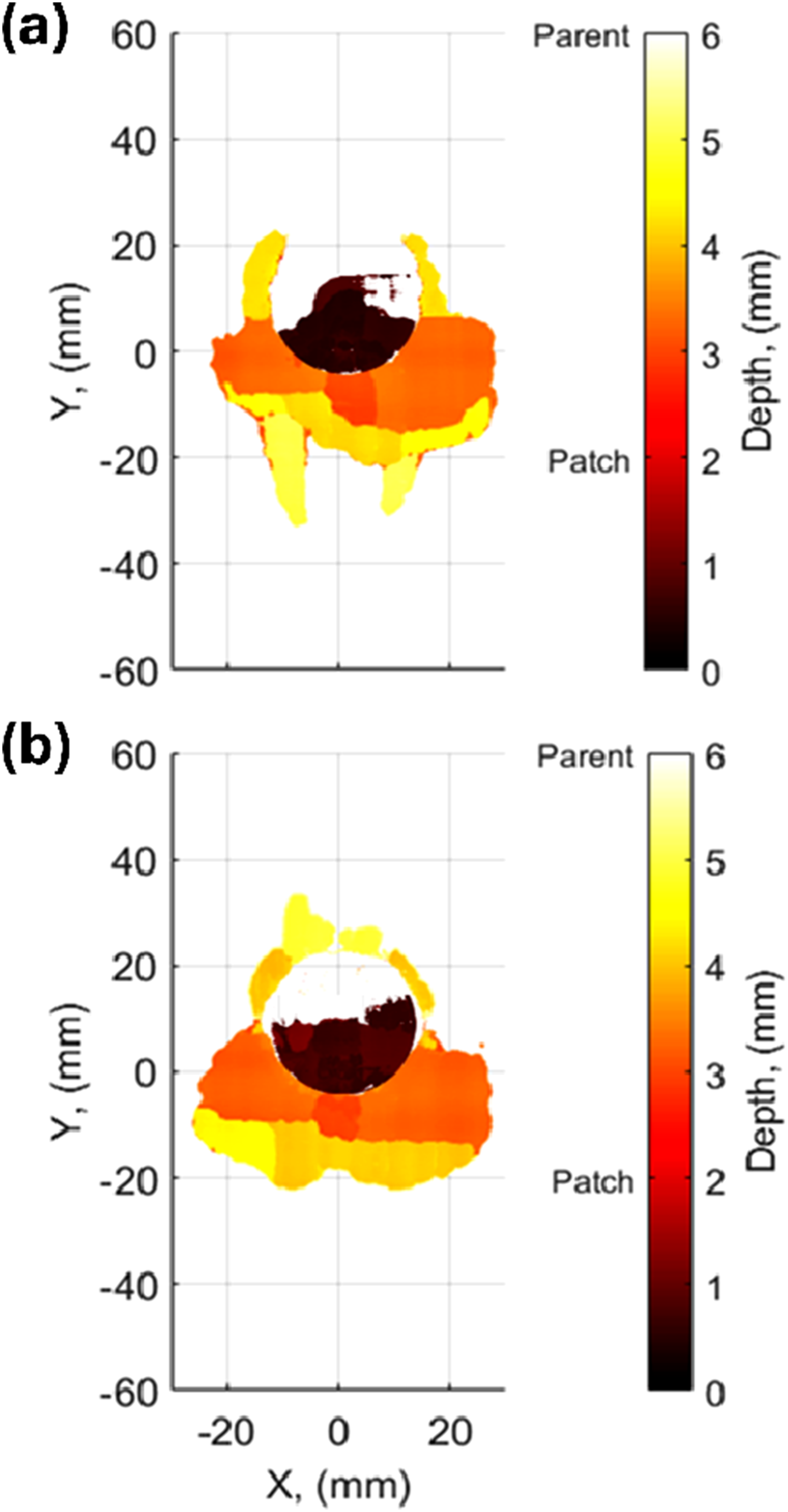
For specimens with repair patches located 25 mm from their impact location, delamination was the first failure mode observed, regardless of their repair methods. An example of a load-time graph with two different failure modes for an impacted specimen is shown in Figure 4(b). Delamination first occurred at 0.5 ms after impact and followed by adhesive cracking 0.1 ms later. As the specimens were impacted beside the patch where the parent laminates have experienced the impact. Both delamination and adhesive cracking occurred at the same time when delamination had propagated towards the repaired region. These observations found the adhesive cracking phase ended 1 ms before the delamination phase, showing delamination remained the primary failure mode for these specimens. The average damage area for both single and double patch repaired specimens were 1290 mm2 and 1225.6 mm2 respectively. Figure 6(a) shows the damage scan of a specimen with a single repair patch at 25 mm from the impact location. The repaired region is outlined using a black dashed line and no damage was found in the patch. None of the specimens with repair patches at 25 mm from the impact location contained damage in the patches. Damage was found on the top-most layer of the parent laminates along the negative y-direction, shown as orange patches in the damage scan. Microscopy was used to confirm that damage was present on the top surface of the specimens. As a crack was found on the top surface of the parent laminates along the y-direction with an example shown in Figure 6(b). The remaining delaminations, coloured in yellow indicating they are nearer to the bottom surface, were relatively small compared to the damage found near the top surface. This was confirmed by repeating the ultrasound C-scans with the specimens flipped upside down. This behaviour was found in five out of the six specimens with patches at 25 mm from the impact location, regardless of the repair methods. Most of the damage in the specimens with patches located 25 mm from the impact location was located nearer to the top surface of the parent laminates. Ultrasonic C-scan (a) for a 25 mm single patch repaired specimen with the patch region (dashed line) and the corresponding microscopy image (b) of the top surface taken at around y = 10 mm.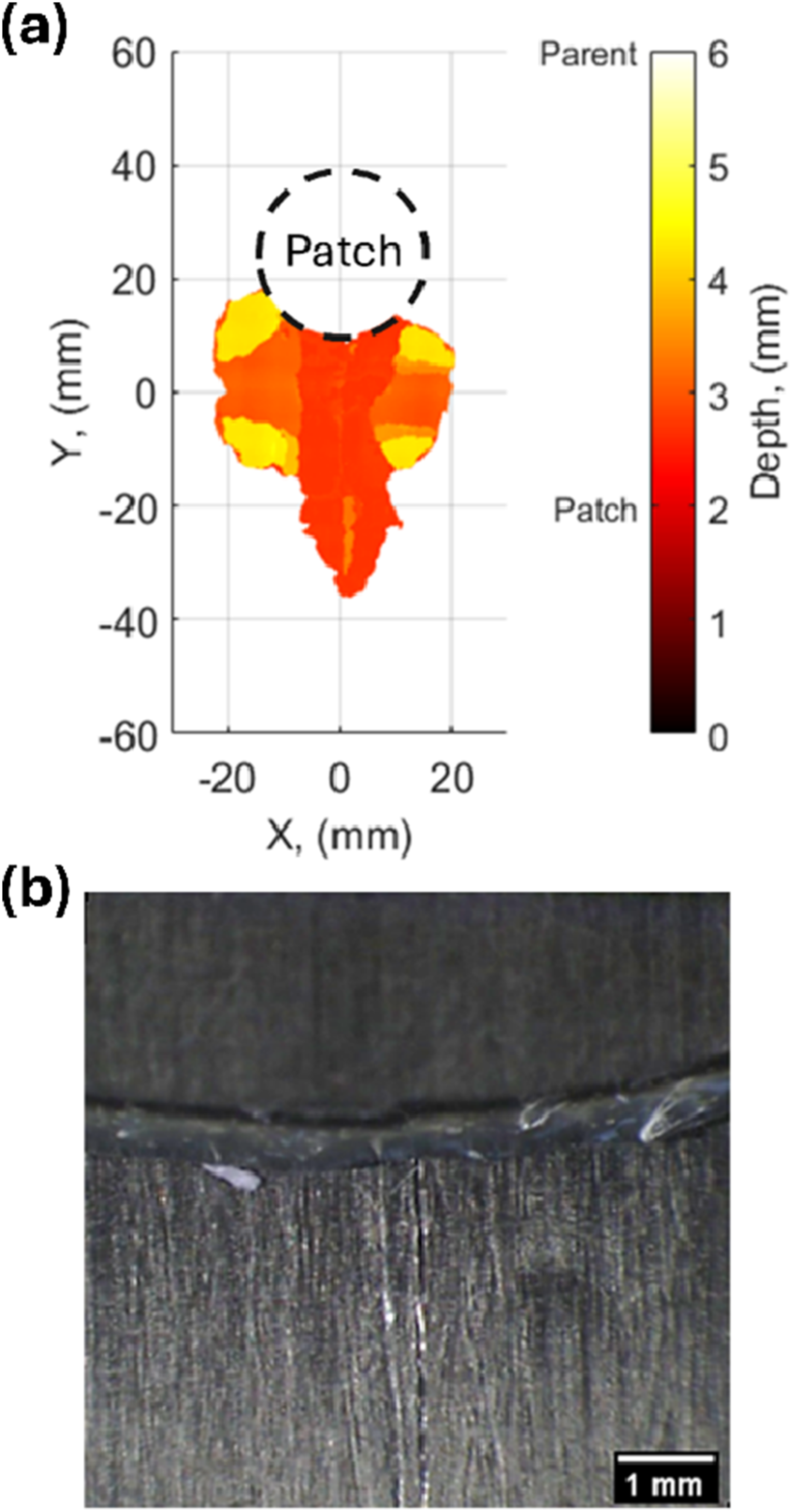
Strain fields on the bottom of all specimens were recorded during the impacts to understand the effect of distance between impact and repair location for both single and double patch repairs. An example of first and second principal strain fields on the surface of a 25 mm single patch repair specimen are shown in Figures 7(a) and (c). They were captured at 1.4 ms after the impact began, showing a strain concentration was near the repaired region in both strain fields. For single patch repair, negative strain values were found between the impact location and repaired patch in the second principal strain field. This scenario was similar for all three specimens with single patch repairs 25 mm away from the impact location. Strain fields for specimens with double patch repairs have some similarities to the single patch repaired specimens, as shown in Figures 7(b) and (d). The shape between both first principal strain fields was similar, a halved elliptical shape. However, the magnitude of the strain fields was significantly smaller for the 25 mm double repair patch specimens. For second principal strain fields, the strain concentration between impact location and repaired patch was also found. Positive strain values were observed for specimens with double patch repairs at 25 mm from the impact location. First principal strain fields and second principal strain fields for a 25 mm single patch repaired specimen (a and c) and a 25 mm double patch repaired specimen (b and d) at 1.4 ms after the impact began.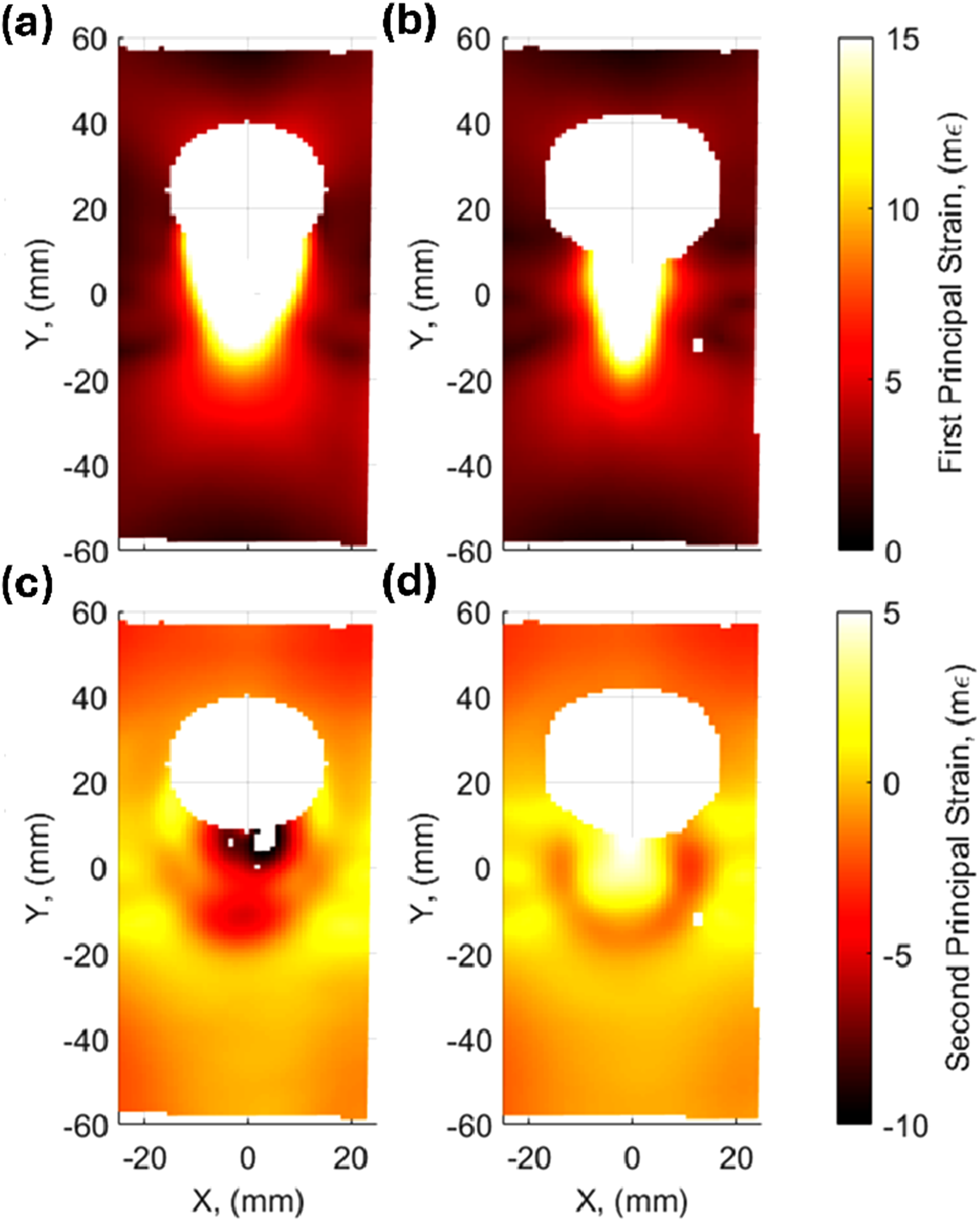
Delamination was the only failure mode found in specimens with single patch repairs located 40 mm away. This failure mode lasted for more than 2 ms during the impact phase. No adhesive cracks were found in any of these single patch repair specimens, confirmed using a microscope. However, this was not the case for the 40 mm double patch repaired specimens where adhesive cracks occured on their bottom patches. Two different failure modes were identified in the double patch repaired specimens: adhesive cracks on the bottom patches and delaminations on the parent laminates which can be observed in the supplementary data (Figure S1). The average damage area for both 40 mm single and double patch repaired specimens were 1467 mm2 and 1714 mm2 respectively. The main difference between both damage morphologies was their damage length, which was the cause of the 15% difference in damage areas. However, no damage was found in the patches or extended beyond y = 25 mm in the y-direction due to the impact for either repair method, see Figure S2. Strain fields for both single and double patch repaired specimens were also assessed to better understand the effect of repair patches since their damage areas had a 15% difference. First and second principal strain fields for all six specimens were identical to each other regardless of their repair methods. These include the size, shape and magnitude of the strain fields. However, the bottom plies for both repair methods reacted differently, resulting in visual differences. The bottom plies were peeled off the rest of the laminate for all single patch repaired specimens but not for any of the double patch repaired specimens. These results were compared to pristine specimens to identify their similarities. The presence of the patches makes it difficult to assess the damage area beneath them, thus for the pristine specimens a cicular region of data located 40 mm from impact location was removed. This corresponded to the area in the patch repaired specimens where data was unavailable. With this region removed for the pristine specimens the average damage area was 1710 mm2, making them comparable to the specimens with double repair patch 40 mm from the impact location.
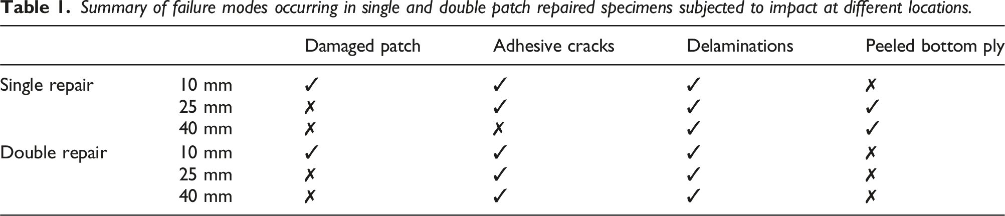
Summary of failure modes occurring in single and double patch repaired specimens subjected to impact at different locations.
Compression after impact tests
Compression after impact tests were conducted on all eighteen repaired specimens, but crushing effects were found for two of them and thus have been excluded from the analysis. Such effects are localized failure of the material near the contact surface with the platen due to the dimensions of the specimen being imperfect. Figure 8 shows the residual strengths of all patch-repaired specimens in comparison to the pristine specimens after 30 J impact. The shaded region was calculated based on the 95% confidence interval of the residual strength of the pristine specimens to identify how impact location affected residual strength. Most of the specimens with impacts located 10 mm and 40 mm from the repair patches fell within the confidence interval, indicating they had similar residual strengths to the pristine specimens. However, two-thirds of the specimens with impacts located 25 mm from the repair patches were above the range, suggesting these specimens had higher residual strength compared to the others based on Figure 8. Residual strength of specimens with both single (circles) and double patch repairs (crosses), impacted at three different locations with the 95% confidence interval (CI) of the residual strength for pristine specimens shown (grey shaded region).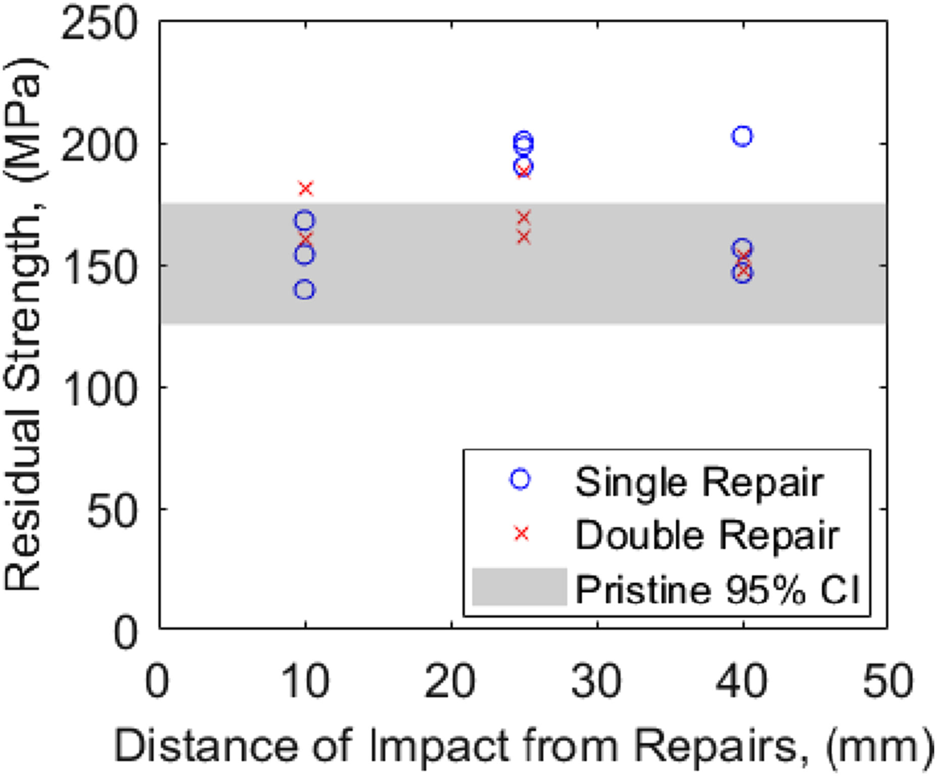
Ultrasound C-scans were performed again after the compression tests to identify their damage morphology. Horizontally aligned fibre breakage was found on the top surface, propagating along the x-direction near both repair patches and impact locations for all 10 mm repaired specimens. A larger delamination was found to surround the patches, regardless of their repair methods. This damage morphology was found for all specimens with impacts located 10 mm from the repair patches with an example shown in Figure 9(a). For specimens where the impact occurred 25 mm from the repair patch, horizontal fibre breakage on the top surface was identified near the repair patch. This was followed by a large patch of delamination propagating towards the positive y-direction, occurring on either side of the patch. These were specimens where the impact occurred beside the patches and such scenario was found in five out of six specimens. This showed pre-existing impact damage did not propagate during the compression after impact tests. An example of this damage formation due to compression is shown in Figure 9(b). Ultrasound scans after compression test for patch repaired specimen with patch region (dashed line) located 10 mm (a) and 25 mm (b) from the impact locations.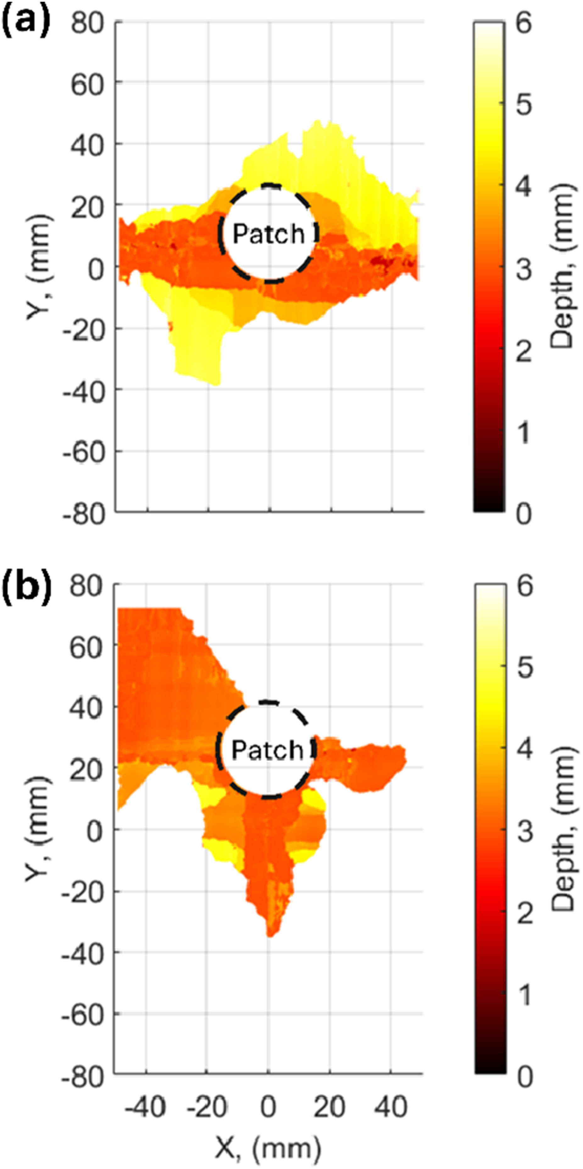
Damage morphology between both single and double patch repaired specimens when the patch was located 40 mm from the impact location were analysed after they had failed in compression. Specimens had large amounts of fibre breakage around their impact locations after they were tested in compression, a similarity observed for both repair methods and all pristine specimens. However, the 40 mm single patch repair specimens has larger delaminations on the bottom surface of the specimen due to the propagation of pre-existing damage from the impact events. Such scenario was not found in any of the 40 mm double patch repair specimens. In contrast, no significant changes were observed for delaminations observed near the bottom surface of 40 mm double patch repaired specimen.
Discussion
This study has impacted both single and double patch repaired specimens at various locations to further understand their effects. Different damage scenarios were observed in this study due to the complexity of impact behaviour for repaired specimens. To fully assess their impact damage behaviour, different approaches were used. This included capturing 300 images using high-speed cameras for each specimen and analysing them manually to gain in-depth knowledge on impact dynamics, allowing the identification of different failure modes between 0.5 and 3 ms after impact. Adhesive cracks, delamination and crack opening were the only failure modes observed in this study, though not all modes occurred in every specimen. Such approach was not performed in any of the previous studies due to the time needed to analyse all images manually. The occurrence of failure modes in composites did not necessarily happen sequentially but two or more failure modes could happen at the same time as shown in Figure 4. The number of observed failure modes decreased as the repaired patches moved away from the impact location, as summarized in Table 1. Specimens with the same combination of repair type and location were found to behave similarly, except for a couple of de-bonded patches. These de-bonded patches were possibly due to variations in bonding surface quality during the manufacturing process, resulting in poor adhesive bonding between the patches and parent laminates.
Since previous studies have only focused on impacting the patches of repaired specimens, three different repair locations were involved in this study to understand their effect on impact behaviour. The damage area for specimens which were impacted on the patches are the smallest among all. They were around 40% smaller than the damage area measured in pristine specimens. This has shown the effectiveness of patch repaired composites, resulting in a better capability of resisting impact damage. As the patches provided more rigidity locally and thus higher impact tolerance. For impacts that occurred beside the patches and away from the patches, the average damage areas was around 25% and 6% smaller than the pristine specimens respectively. This shows the effect of the patch reduces as the impact location moves away from the repair patches. Such behaviour was also confirmed by comparing strain fields, damage size, and damage shape to the pristine specimens. Hence, impact damage which occurs further than 40 mm from the patch repair will have similar behaviour to the pristine specimens.
In addition, both single and double patch repair composites were introduced in this study to understand their effectiveness. Patches located on the bottom surface have provided an alternative load path, allowing damage to propagate through the adhesive when impact occurred on the patches. This caused unexpected small delaminations on the other side of the patch relative to the impact location, as shown in Figure 5. Similar mechanisms have also been reported by Liu and Yan 9 when impacting scarf repaired composites. The propagation of damage for these specimens was confirmed by monitoring the raw images from the high-speed cameras. This occurrence was only found in double patch repaired specimens when patches were directly impacted. This damage propagated further during the compression after impact tests and caused larger amounts of damage compared to the others. This was found by comparing both Figures 5(b) and 9(a). Both ultrasound scans are from the same specimen where the former was measured before the compression test and the latter was after the test. For specimens impacted beside the patches, the location of strain concentration, damage size, and damage shape were similar for both repair methods. The only difference between them was the magnitude of the strain concentration in the second principal strain fields. For specimens with single patch repairs, negative strain values were found whereas positive strain values were observed on the double patch repaired specimens. Despite the magnitude difference in strain values, there was no variation in damage behaviour between both repair methods, as damage was consistently found on the top surface. Specimens being impacted next to the patches had distinct strain distributions where strain concentrations were found near the patches instead of impact location. This behaviour was not observed in specimens impacted elsewhere, and resulted in different impact damage for these specimens. Previous studies18,22 have primarily reported the occurrence of strain concentration near open holes during impact. However, no prior studies have examined how these influence the post-impact failure mechanisms and damage morphology of patch repaired composites. The present findings highlight how impact locations affect composite damage mechanisms due to stress redistribution, particularly impacts that are close but not directly on the repair patch. This suggests engineers should not only account for the location of repairs but also consider the likelihood of future impact events in surrounding regions of the repaired component.
One advantage of double patch repairs is their effectiveness in preventing the bottom plies from peeling from the patched hole during impacts. The bottom plies for specimens with single patch repairs at 25 mm and 40 mm were found to have peeled post-impact. In contrast, double patch repairs effectively prevented the bottom plies from peeling and inhibited delamination growth on the opposite side of the patch to the impact location. This was confirmed using both ultrasound scans and microscopy, which showed no damage beyond the patched regions. The average damage area for 40 mm double patch specimens was similar to the pristine specimens but 15% smaller for 40 mm single patch repaired specimens. This suggests that damage formed in single patch repaired specimens were more localized and severe compared to the double patch repaired specimens. This was found by comparing the damage found before and after the compression tests. The 40 mm single patch repaired specimens resulted in a larger delamination area after the compression tests compared to the 40 mm double patch repaired specimens, suggesting they are weaker in comparison. These findings show that single and double patch repaired specimens have different impact behaviour.
Compression after impact tests were conducted on all specimens in this study to identify how different impact locations could affect residual strength after being subjected to 30 J impact. Some variations in residual strength were observed which are likely due to a combination of factors, such as manufacturing imperfections in the composite and variability in repair patch quality. Repaired specimens with patches located 10 mm and 40 mm away from the impact location had similar residual strength as the unrepaired specimens, resulting in the average residual strengths of 162 MPa and 160 MPa respectively. However, the average residual strength for specimens with patches located 25 mm away from the impact location was 185 MPa, around 15% higher than the others. These specimens have a larger delamination area on the top surface but smaller area closer to the bottom surface. This suggests the severity of the impact damage formed in these specimens was less than the others and hence resulted in higher residual strength when tested in compression. This might be due to the differences in strain distribution in comparison to specimens with other impact locations. Based on the experimental results, all repaired specimens had similar or higher residual strength compared to the unrepaired specimens, regardless of their impact locations. This shows the effectiveness of the repairs since it is expected that repaired components should have the same load-bearing capacity as pristine components.
Damage morphologies of all repaired specimens were studied after they were loaded to failure in compression. Large amounts of fibre breakage propagating horizontally across the width of all specimens were found but the location of this crack varied. For all 10 mm specimens, fibre breakage was found near the repair patches, which was also near to the impact location. This is because this location was the weakest among all specimens that also contained impact damage. However, most of the specimens with repair patches located 25 mm from the impact location had fibre breakage around the patch region. This means the stress concentration due to the repair patches was higher than that induced by the impact damage, supported by lower amounts of total damage measured in these specimens. For 40 mm specimens, all fibre breakage was found near the impact location, similar to the pristine specimens. This shows that the impact locations significantly affected composite residual strength and damage morphology during the compression after impact tests.
This experiemental investigation has provided significant insights into the impact tolerance of patch repaired components. This includes a different impact behaviour when patch repaired specimens were being impacted next to the patches which resulted in a higher residual strength. Other studies only focused on impacting at the centre of repair patches, this is an unlikely scenario in real-life as impact events can occur anywhere on a structure. Hence, a wider range of impact locations were introduced in this study, with impacts on the repair patches, impacts next to the patches, and impacts away from the patches. This study has demonstrated that impacting specimens 40 mm from their repaired locations resulted in similar impact behaviour to that found in prisitine specimens. For impacts closer to the patches, different impact behaviour and damage shapes were observed, this significantly affected the damage tolerance of repaired composites. Such detailed information related to the effect of impact locations on repaired composites has not been reported in other studies.
Conclusions
This study has explored the effect of single and double-sided patch repairs with multiple repair locations on specimens during impact events. For the first time, quantitative comparisons between eighteen repaired specimens were carried out using high-speed digital image correlation (DIC) data to understand their damage behaviour. The distance between impact location and patch repair significantly influenced the impact behaviour. This resulted in different damage size and shape despite being impacted at the same incident energy. Patch repaired composites were found to improve material impact damage tolerance, with a 40% reduction in damage area for impacts occurring on the patches. This was supported by monitoring their strain fields, damage size and shape, failure modes, residual strength and their damage morphologies after the compression test. The presence of an extra patch on the bottom surface was also found to cause distinct impact behaviour. This has the primary benefit of preventing bottom plies from peeling, but also allowing damage propagation through the adhesive located at the bottom surface that was not expected. This comprehensive experimental study provides a better understanding on both damage evaluation and behaviour during impact of repaired components. This information is important for effective risk management of patch repaired structures, providing valuable data on their performance under realistic service conditions.
Supplemental Material
Supplemental Material - Experimental study on the effect of distance between impact and patch repair location in carbon fibre composites
Supplemental Material for Experimental study on the effect of distance between impact and patch repair location in carbon fibre composites by E.Y.H. Chai, W.C. Wang and W.J.R. Christian in Journal of Composite Materials.
Footnotes
Author contributions
EYHC performed the experiments, processed the experimental data and wrote the first draft of the manuscript. WJRC and WCW supervised the project. All authors contributed to the final manuscript.
Declaration of conflicting interest
The author(s) declared no potential conflicts of interest with respect to the research, authorship, and/or publication of this article.
Funding
The author(s) disclosed receipt of the following financial support for the research, authorship, and/or publication of this article: EYHC received a scholarship from the University of Liverpool and National Tsing Hua University dual PhD programme.
Ethical statement
This article does not contain any studies with human or animal participants.
Data Availability Statement
Data available upon request.
Supplemental Material
Supplemental material for this article is available online.
References
Supplementary Material
Please find the following supplemental material available below.
For Open Access articles published under a Creative Commons License, all supplemental material carries the same license as the article it is associated with.
For non-Open Access articles published, all supplemental material carries a non-exclusive license, and permission requests for re-use of supplemental material or any part of supplemental material shall be sent directly to the copyright owner as specified in the copyright notice associated with the article.