
Abstract
Over the past decades, the importance of lightweight structures in the aircraft and automotive industries has steadily increased due to regulations aimed at reducing global warming. Work hardened steel alloys are commonly used for lightweight applications, but they face stability issues when the material thickness reaches certain thresholds. Fiber Reinforced Plastics (FRP) offer a viable alternative due to their high strength-to-weight ratio, but they are often expensive due to long production cycles and high material costs. A feasible solution lies in hybrid lightweight designs that utilize expensive FRP materials only in highly stressed areas, achieving a balance between low mass and acceptable cost. These hybrid structures are lighter than metal components and more cost-effective compared to fully FRP structures, without compromising mechanical properties. This study focuses on producing rotationally symmetrical hybrid structures using Resin Transfer Molding (RTM) combined with vacuum assistance in a single-stage process. The research examines the effects of injection pressure, mold temperature, and the interface between metal and FRP. The mechanical characterization of these hybrid structures was conducted to assess their performance under torsion, compression, and interlaminar shear strength (ILSS) loading conditions. The results indicate that hybrid designs can offer a lightweight alternative without compromising mechanical properties.
Keywords
Introduction
Hybrid manufacturing techniques have gained importance because of their ability to produce lightweight structures with optimized properties. The main concept of hybrid manufacturing is using multiple materials to create structures that compensate for each other’s weakness without compromising their original properties, resulting in superior components that cannot be made from a single material.1–3 Metal-FRP hybrid structures have been widely studied over the past few decades due to their desirable characteristics, including a high strength-to-weight ratio, improved fatigue performance, corrosion resistance, and vibration damping.2,4,5 FRP-metal hybrid structures were first introduced for aerospace fuselage structures to replace the aluminum alloys for further weight reduction. 6 Metal-FRP hybrids are now used in various car body parts due to their lightweight properties, with a potential application in the automotive sector for crashworthiness systems. 7 Normally, FRP alone cannot be used for crashworthiness because its failure mode is characterized as brittle when loaded in the fiber direction due to unstable interlaminar layers under dynamic conditions. However, the failure behavior of the complete structure can be modified to a ductile failure by integrating metals, leveraging the plastic deformation phase of metals.8–10 Given these benefits, Metal-FRP hybrids have been widely adopted in high-performance and luxury vehicles for applications requiring high impact resistance, energy absorption, and enhanced mechanical performance.11,12 These hybrid structures not only meet the stringent safety requirements but also contribute to weight reduction, which is crucial for improving fuel efficiency and reducing emissions in modern vehicles.13,14 Consequently, extensive research and development have been directed toward optimizing Metal-FRP hybrids for use in automotive systems, making them a promising solution for future vehicle designs including electrical configurations.15–20
Resin Transfer Molding (RTM) is a well-established technique for manufacturing complex FRP structures and can also be used to produce hybrid structures.
21
The RTM process begins with preparing a mold, which is coated with a release agent to prevent sticking and ensure easy removal of the final product. A fiber preform, typically made from materials such as glass, carbon, or aramid fibers, is then placed within the mold cavity. Thermosetting resin is injected into the mold under controlled pressure, ensuring thorough impregnation of the fiber preform. This step is crucial to avoid defects such as voids or dry spots. The mold is then maintained at elevated temperature to cure the resin, solidifying it and binding the fibers into a rigid composite structure. After curing, the mold is opened, and the finished composite part is demolded, often requiring further finishing processes like trimming or machining to meet specific requirements. Figure 1 shows the block diagram for the RTM process that produce Metal-FRP hybrid structures. RTM is favored for its ability to produce complex shapes with high fiber volume fractions and excellent surface finishes, though it demands careful management of resin infiltration and curing cycles to ensure high-quality outcomes.
22
Block diagram showing the process cycle of Resin Transfer Molding (RTM).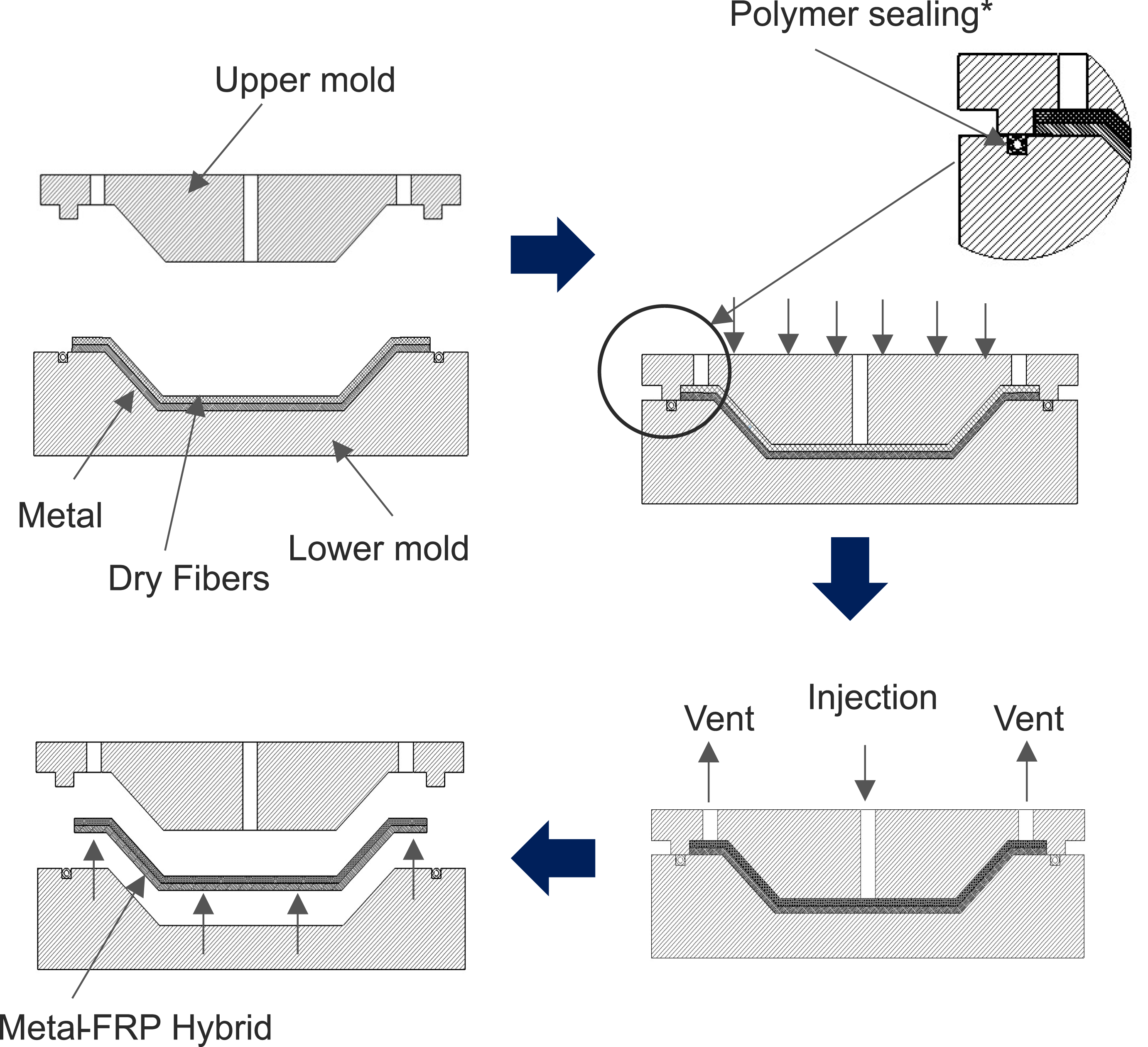
However, there are challenges in the RTM process, especially for parts with high fiber content (typically greater than 40%), which decreases the permeability of the preform, leading to long filling times, incomplete impregnation, and high void content.23–25 Several strategies have been developed to modify the conventional RTM process.26,27 High Pressure Resin Transfer Molding (HP-RTM) was introduced to inject resin at pressures as high as 500 bars, reducing filling time but causing voids due to insufficient time for trapped air to escape.
28
Vacuum Resin Transfer Molding (VA-RTM) addresses this by evacuating the mold before and during the injection phase. Another improvement is Compression Resin Transfer Molding (CRTM), where the mold is partially opened until the end of resin injection and then closed, squeezing the resin into the preform. Therefore, instead of going through the entire fiber stacking length as in RTM, the CRTM process wets the fibrous reinforcement by penetrating in the thickness direction.29,30 However, CRTM came with a new challenge, as the wetting of fiber is not homogeneous along the thickness.
30
Light Resin Transfer Molding (LRTM) was developed to reduce filling time for large molds by first circulating resin around the mold’s circumference and then impregnating the fibers in a convergent phase. Despite these advancements, the selection of appropriate process parameters remains crucial.
31
Parameters such as injection pressure, mold temperature, location of inlets and vents, fiber volume, fiber layup, vacuum application, and injection mass flow rate all influence the mechanical properties of the final composite.32–34 These parameters significantly impact the flow front path of the matrix, which is the most critical aspect of the RTM process.
35
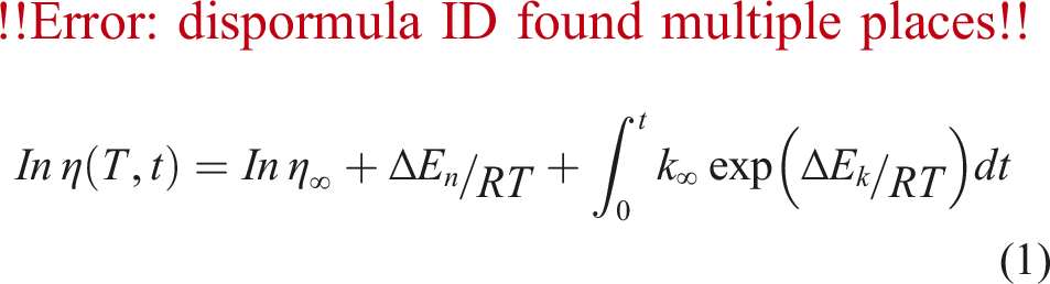
Effective management of these variables is essential to achieving high-quality composite structures. To study the relationship between these parameters and the fluid front concerning materials, many mathematical models have been proposed that account for time and temperature dependencies. The relationship between the fluid flow front and process parameters is described by the Arrhenius equation as shown in equation (1).
36
Where η(T, t) represents the viscosity at temperature T, at a time t, ʽ

Another critical factor in producing hybrid structures is the interface between metal and FRP. The interface plays a major role in metal-FRP hybrids as it is crucial for transferring loads between them, directly influencing the component’s mechanical properties.38–41 Modifying a suitable polymer to increase bonding strength at the interface between metal and FRP is highly challenging and costly due to the differing physicochemical properties of the two materials. However, increasing the interlocking strength through modified metal surfaces can be easily and efficiently implemented.42,43 These surface treatments are classified into three categories: mechanical, chemical, and energy methods. Mechanical methods include techniques such as grit blasting, sanding, and creating micro-grooves on the metal surface. These techniques increase the roughness and surface area, providing more contact points for the FRP to adhere to. Chemical methods involve treatments like anodizing or applying chemical primers that enhance the chemical bonding at the interface. 44 Energy methods, such as laser ablation or plasma treatments, modify the surface properties through energy application, creating a more reactive surface that improves bonding with FRP. For instance, laser ablation, an advanced energy method, uses laser beams to precisely remove material from the metal surface, creating micro-scale features that significantly enhance the bonding area. 45 This method is highly controllable and can be tailored to create specific surface patterns that optimize the mechanical interlock between metal and FRP. In the current study, mechanical methods based on sandblasting were used for altering the metal surface to increase the surface area and create undercuts. This approach ensures better mechanical interlocking, leading to improved load transfer and enhanced mechanical properties of the hybrid structure.
Materials and methods
In the current study, various structures of an automobile were studied to find the potential application of hybrid structures that results in weight saving and at the same time improved properties. Based on literature, some of potential areas that can use hybrid structures in an automotive are A-pillar, B-pillar, C-pillar, Crash-box, and Drive shaft. One of the common challenges in hybrid structures is residual stresses generated due to different thermal expansion coefficients of metals and FRPs. However, this can be reduced with tailoring the fiber directions or can be used to increase the adhesive force between metal and FRP if the structure is cylindrical. Out of five structures mentioned above, drive shaft cross-section is cylindrical in shape that can use residual stresses for a better adhesiveness between metal and FRP. Based on this approach, a hollow cylindrical shaft geometry that resembles the cross section of vehicle’s drive shaft was selected. The suitability of the RTM process for producing such rotationally symmetrical parts is also highlighted, as these cannot be effectively manufactured using methods like prepreg pressing.
The dimensions of the hybrid drive shaft were selected based on the literature survey. Diameter, thickness, and length are three different dimensions that should be determined. The thickness of the drive shaft should be as minimum as possible so that the inertia is kept to minimum. The typical thickness of shafts ranges from 3 mm to 15 mm depending on the type of vehicle. Diameters range from 42 mm to 60 mm depending on the material used and type of vehicle. Length of the dive shaft depends on the type of drive shaft configuration and material used that ranges from 850 mm to 2000 mm. The configuration of the drive shaft is classified based on the number of segments it’s made from. For example, a three-part drive shaft is dived into three segments and is connected using universal joint to reduce the bending loads when the length of power train is too long. In the current work, the thickness of the drive shaft was kept to minimum that is 3 mm and a mid-value of 54 mm was selected for the outer diameter. The thickness of the metal is 1 mm, whereas CFRP is 2 mm thick. The selected 2 mm thickness ensures proper distribution of stresses across the CFRP layer while maintaining adequate bonding with the underlying metal, contributing to optimal load transfer. This balance of material thickness also helps in reducing manufacturing complexities and achieving a uniform resin flow during the RTM process, which is critical for preventing voids and ensuring consistent fiber wetting. Since the length of the drive shaft has lesser influence as they can be made from, number of segments was kept to a minimum value, which is 320 mm.
Materials
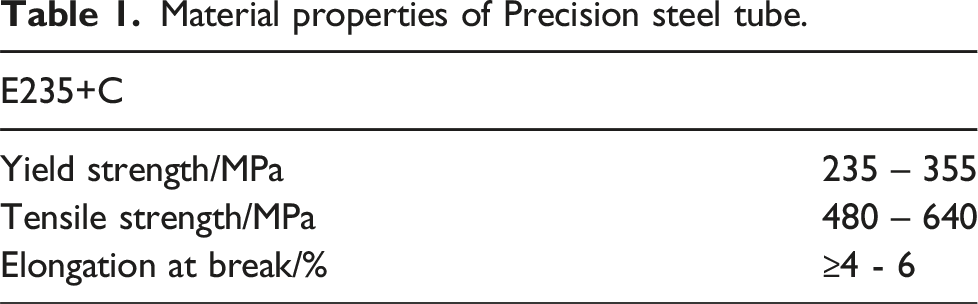
Material properties of Precision steel tube.
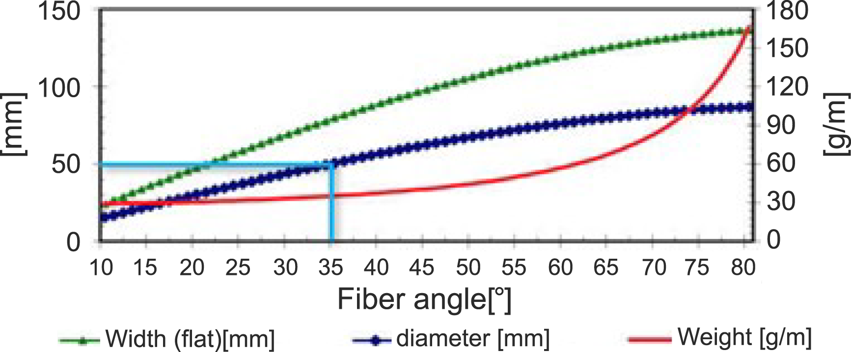
Angle of fibers with respect to different diameters.
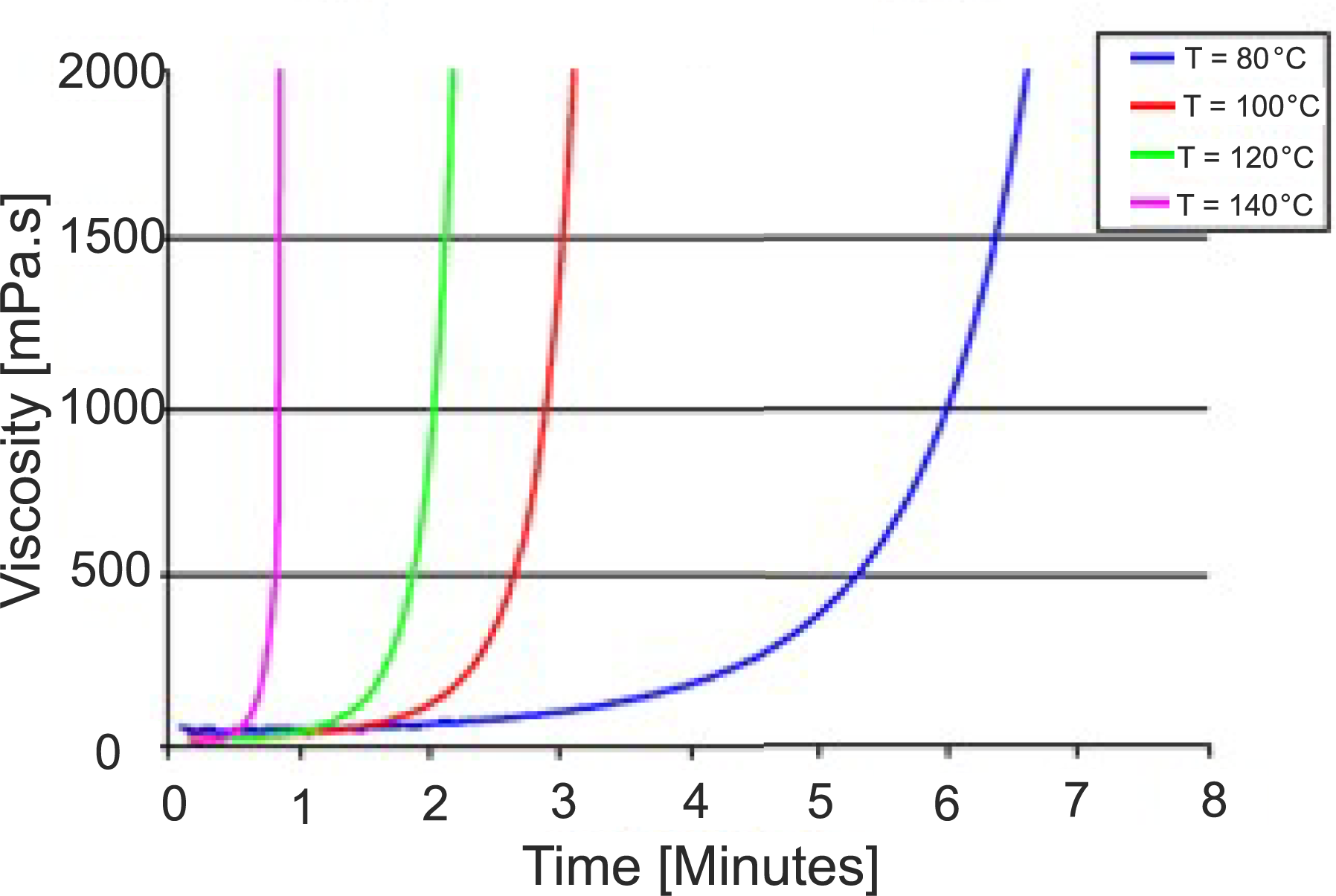
Viscosity with respect to time at various temperatures of epoxy based Epikote Resin 05,475 and Curing Agent 05,443.
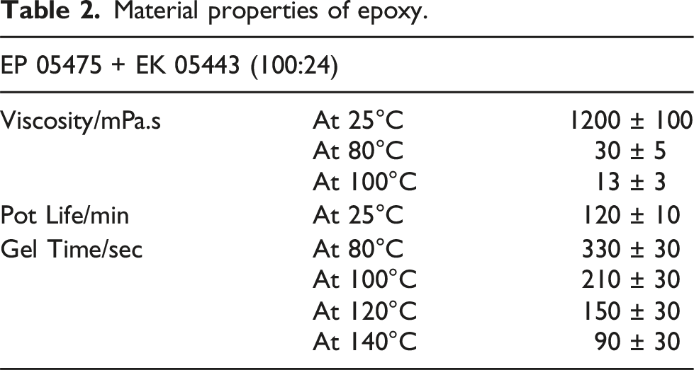
Material properties of epoxy.
Hybrid sample production
Sample types based on Taguchi L9 array for parameter study.
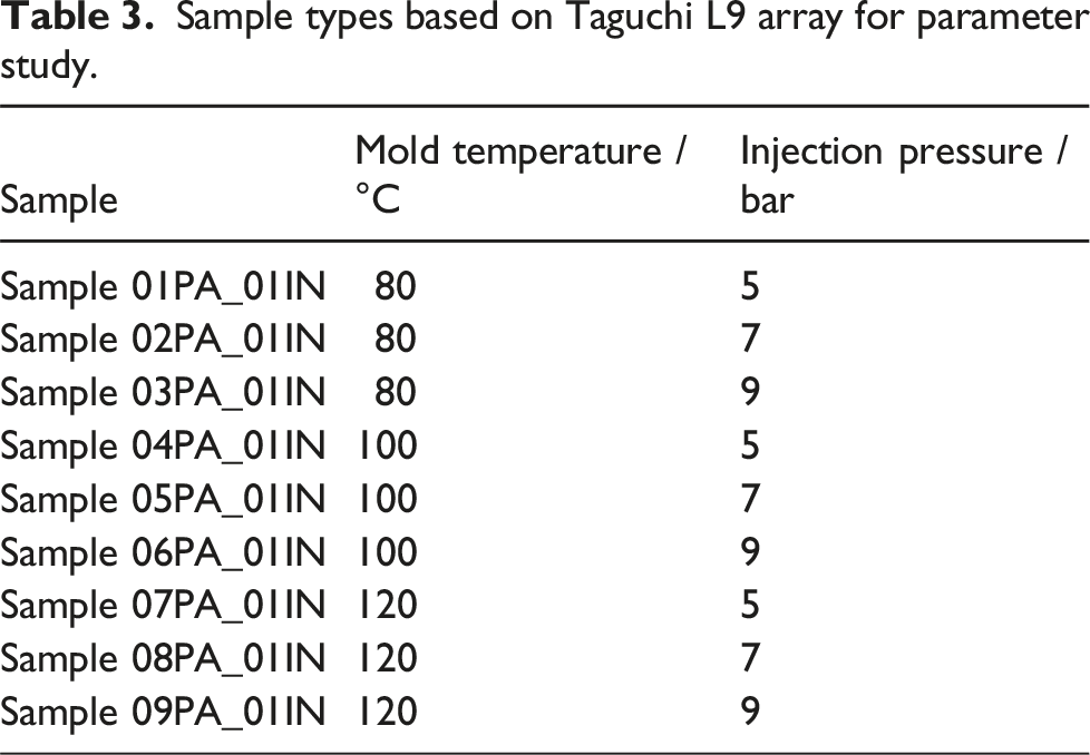
The production of samples starts with cutting the dry fibers based on the dimensions required. A total of six layers of dry fibers are cut to form a 2 mm thick composite layer with 55 % fiber volume. The CFRP are stacked on the steel one by one with binders added for each layer manually. Once the fibers are stacked with binder, they are tapped with a special shrinkage tape of 0.05 mm thickness, as shown in Figure 4. The sample is moved to the mold for preforming, where a temperature of 140°C is applied for 10 min. Due to this step, the binder melts and then solidifies when kept at room temperature creating a bond between dry fibers of different layers. This preform stage prevents fiber deformation or fiber washout during injection phase. After discarding the release foil, the preform is placed in the mold. The mold is now closed, and the injection pressure is adjusted according to the sample number based on Table 3. Schematic diagram showing the production cycle of Hybrid sample; (a) adding glass fleece; (b) adding CFRP; (c) adding binders; (d) tapping the sample with shrinkage tape for preforming and (e) Hybrid shaft.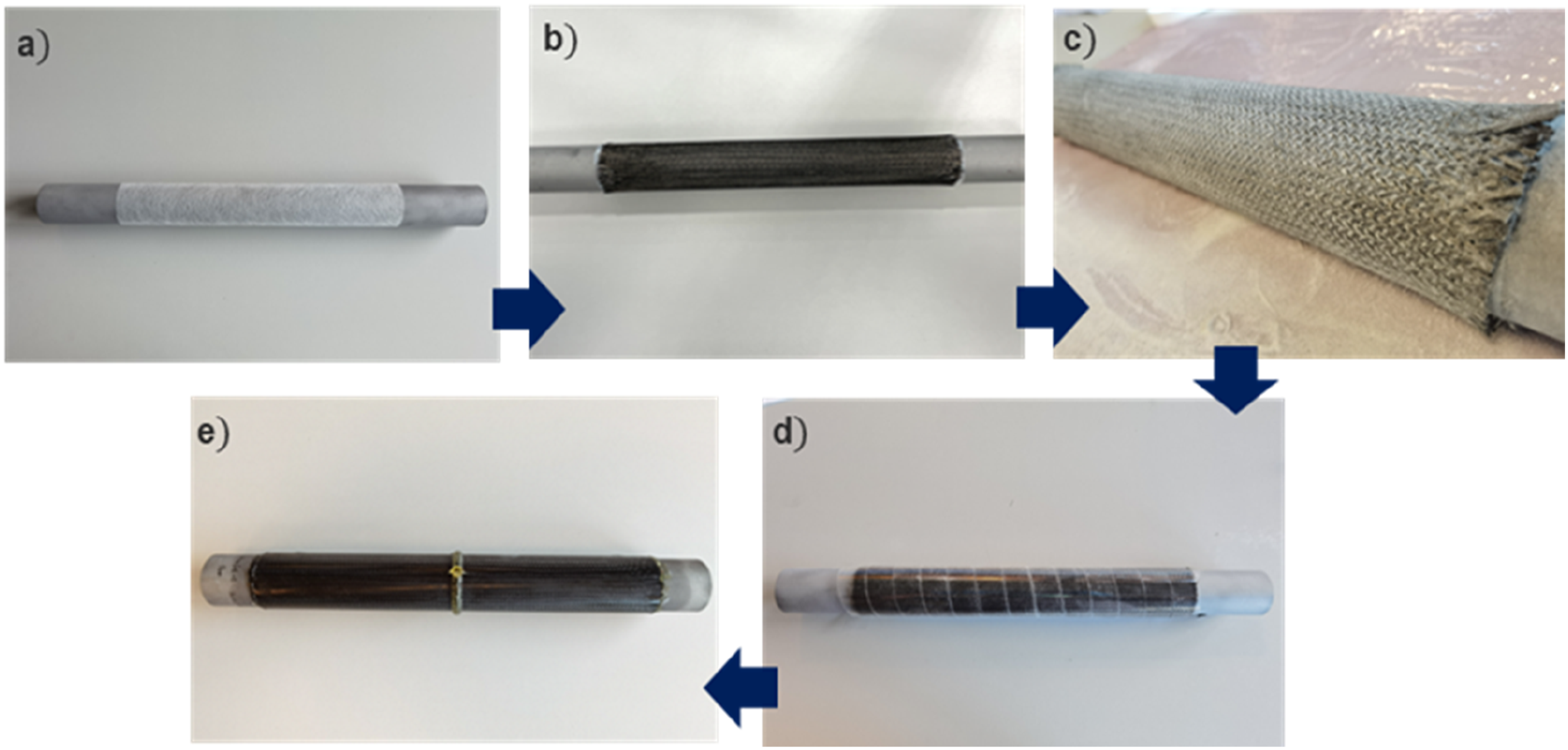
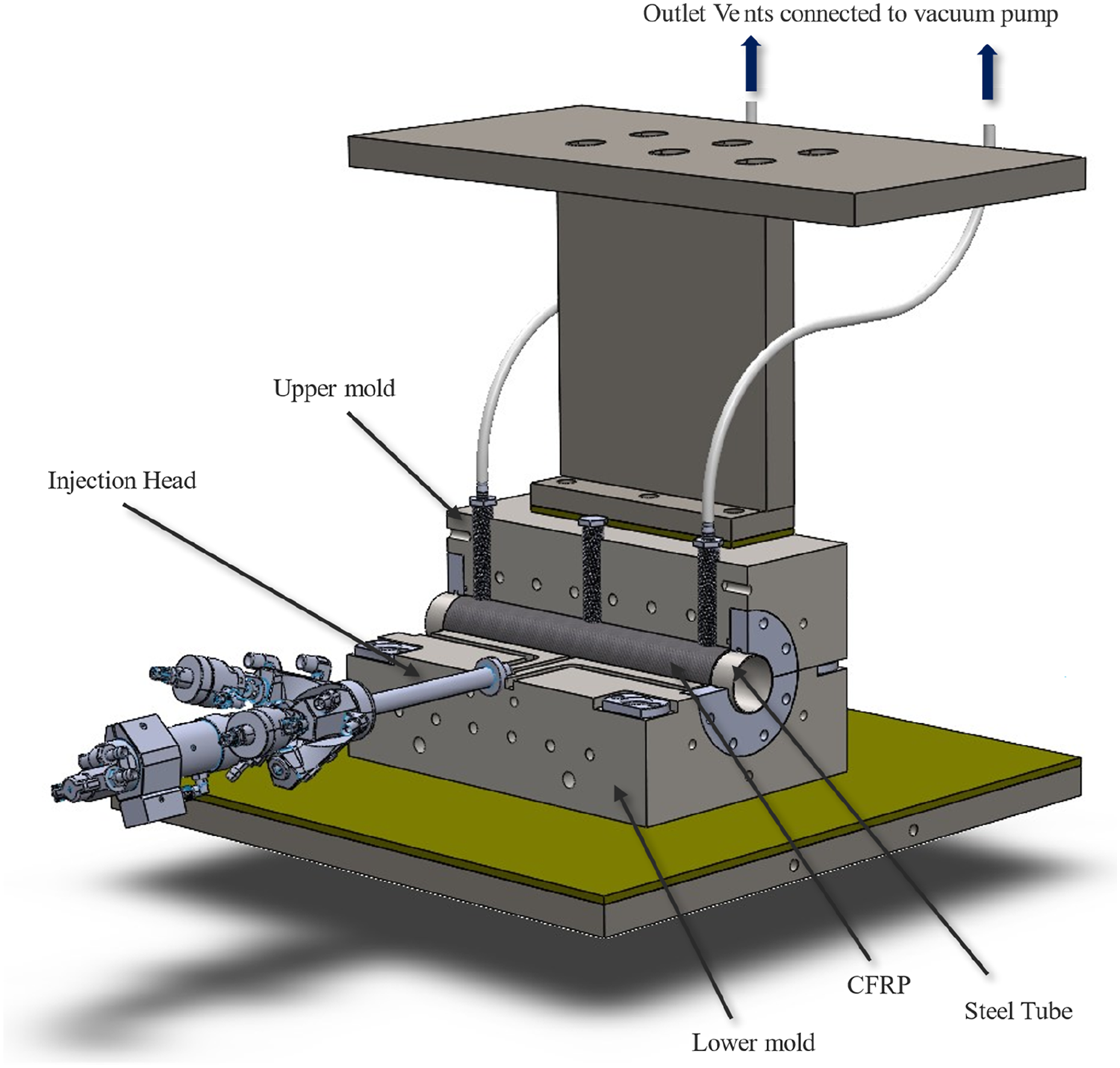
Another parameter that was controlled is the initial mass flow rate of the matrix system before the process reaches the injection pressure. Once the injection pressure is reached, the mass flow rate is automatically reduced to maintain the given injection pressure. An offset of 0.5 bar was given in the machine so that the pressure can range from 6.5 bar to 7.5 bar for 7 bar injection pressure. Figure 5 show the injection pressure and mass flow rate recorded over the time during the injection phase. The initial mass flow rate was kept at 0.15 kg/min for all hybrid samples. The machine has a record frequency of 1 Hz. Additionally, for all the hybrid samples, the machine was programmed to inject 0.21 kg of resin into the mold and stop automatically. Based on theoretical calculation, 0.14 kg of matrix system should be injected to maintain 55 % fiber volume for the hybrid samples produced. However, an extra 0.07 kg was added to offset the matrix wasted because of inlets head volume and to maintain a minimum of 90 sec on injection time. The excess resin is collected at the outlet vents that are equipped with resin trap pot. During the entire production cycle, the mold was connected to a vacuum pump via outlet vents at both ends of mold and maintained at ∼0.015 bar (absolute pressure). Figure 6 shows the production setup of the current study. Production data points when injection pressure was set to 5 bar and initial mass flow rate of 0.15 kg/min. Schematic diagram showing the production setup for VA-LRTM.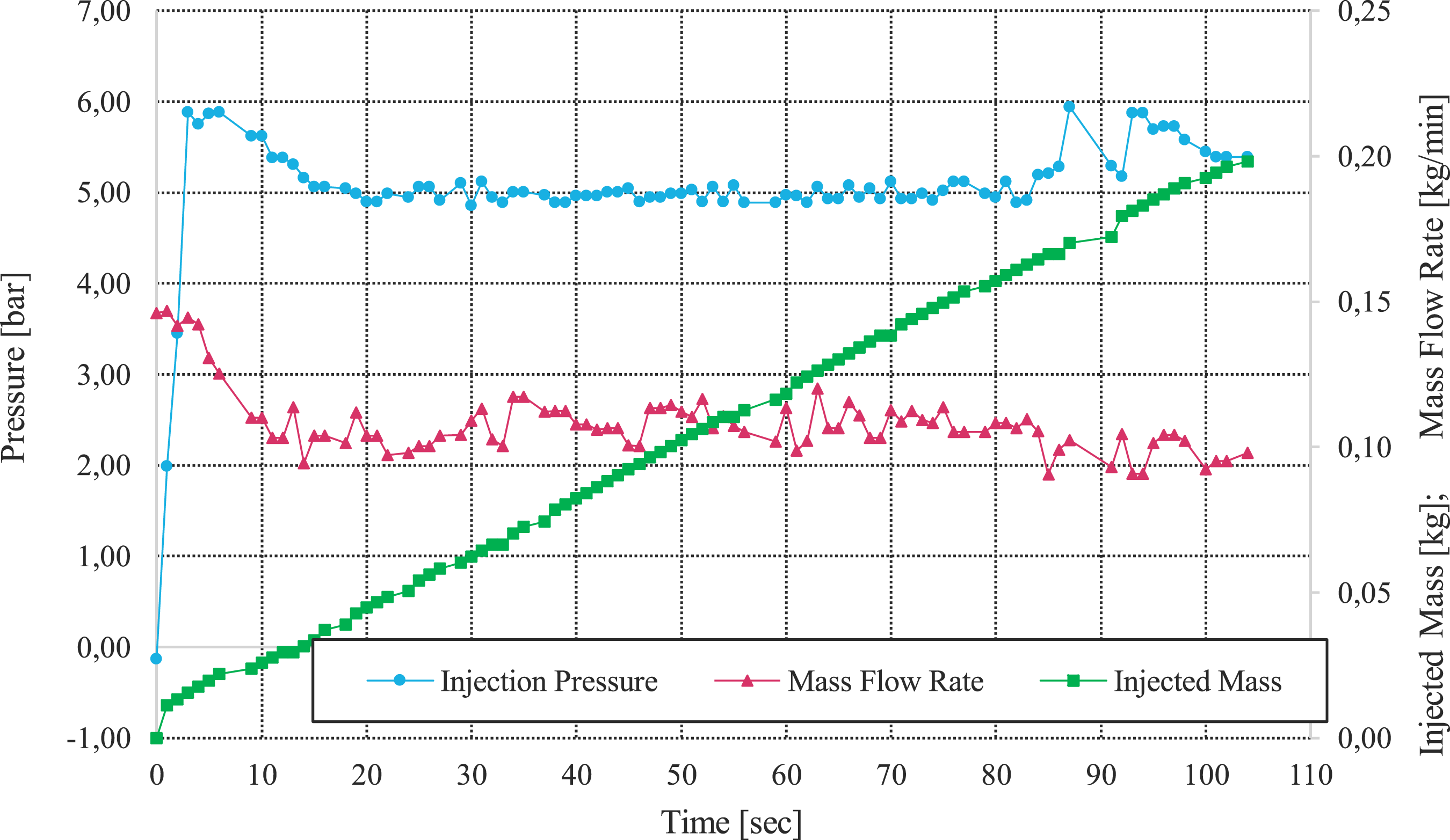
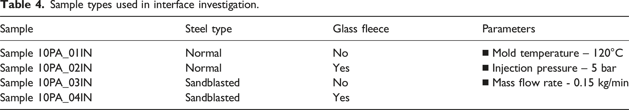
Sample types used in interface investigation.
Results and discussion
Interlaminar shear strength (ILSS)
Samples according to Table 3 were produced with respective injection pressure and mold temperature. To evaluate these samples, the interlaminar shear strength (ILSS) for the cylindrical shafts was assessed, based on the shear strength testing of flat composite specimens. The hybrid shafts were sectioned into 20 rings, each 5 mm thick, and subjected to shear testing using a shear-edge device, which pressed the steel ring out of the CFRP structure as shown in Figure 7. The recorded force was normalized against the steel/CFRP interface area to determine shear strength, reflecting the interfacial bonding quality. By designing the die and punch precisely, the force flow was directed through the interface, establishing a defined stress state, which accurately reflects the interfacial shear strength rather than simply adhesive strength. Schematic diagram showing sample sliced across its length into specimens for testing their respective interlaminar shear strength (ILSS).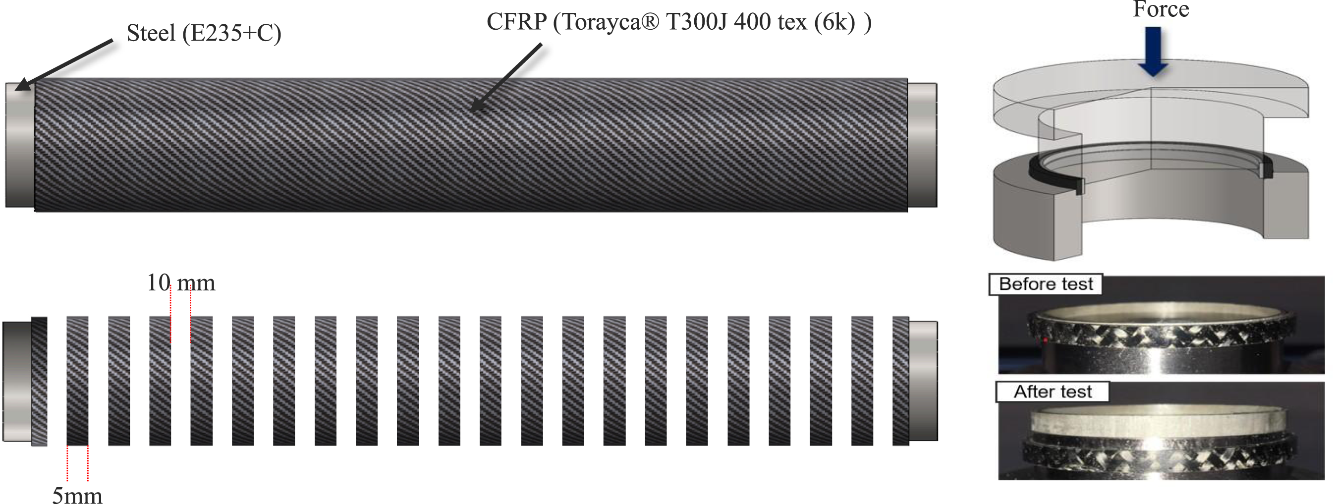
The samples were tested and grouped based on injection pressure and mold temperature as shown in Figure 8. The results are based on an average value of 20 specimens on each sample and their standard deviation is recorded as an error bar. A difference of 26 % in ILSS can be noted between stronger samples (injection pressure – 5 bar & mold temperature 120°C) and weaker samples (injection pressure – 9 bar & mold temperature 80°C). Based on mold temperature, a liner trend can be spotted across the nine samples. Even with different injection pressures, higher mold temperature has better ILSS values. This phenomenon can be derived from the temperature versus viscosity of the matrix system. Higher temperature results in lower viscosity that makes the matrix flow better between fiber tows and increases its wetting property of the fibers. Further increase in mold temperature from 120°C can’t be considered for the selected resin as the Gel time is reduced to 90 ± 30 sec at 140°C affecting the injection time. Injection time is the total time the machine needs to pump the 0.21 kg of resin into the mold. ILSS results of samples with respect to mold temperature.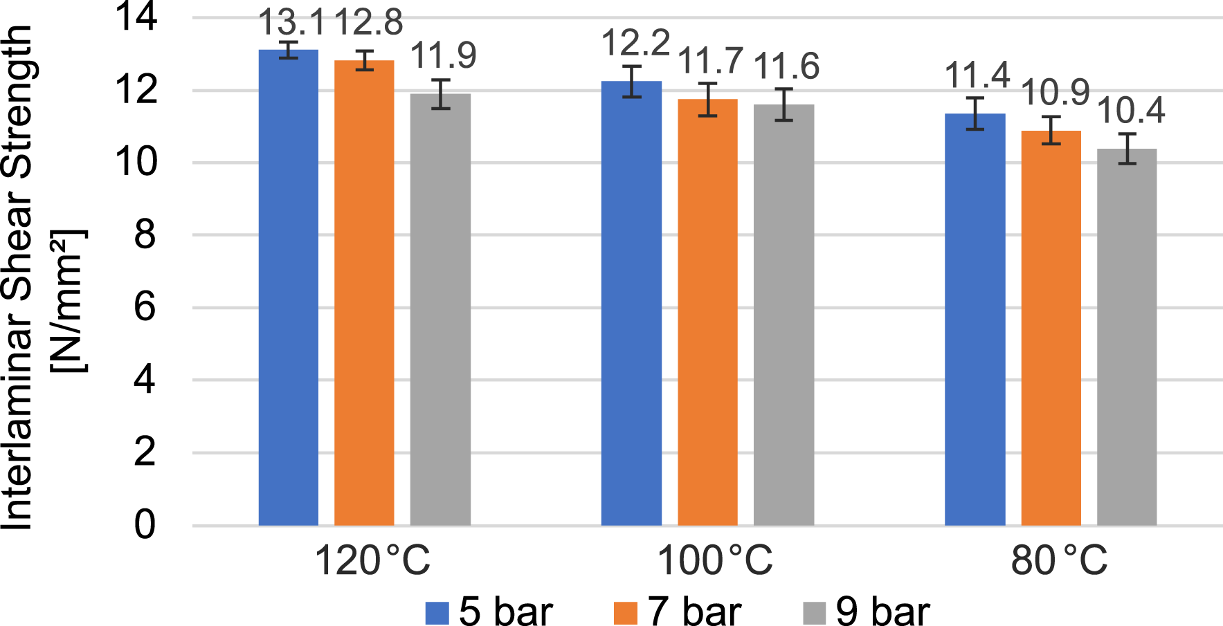
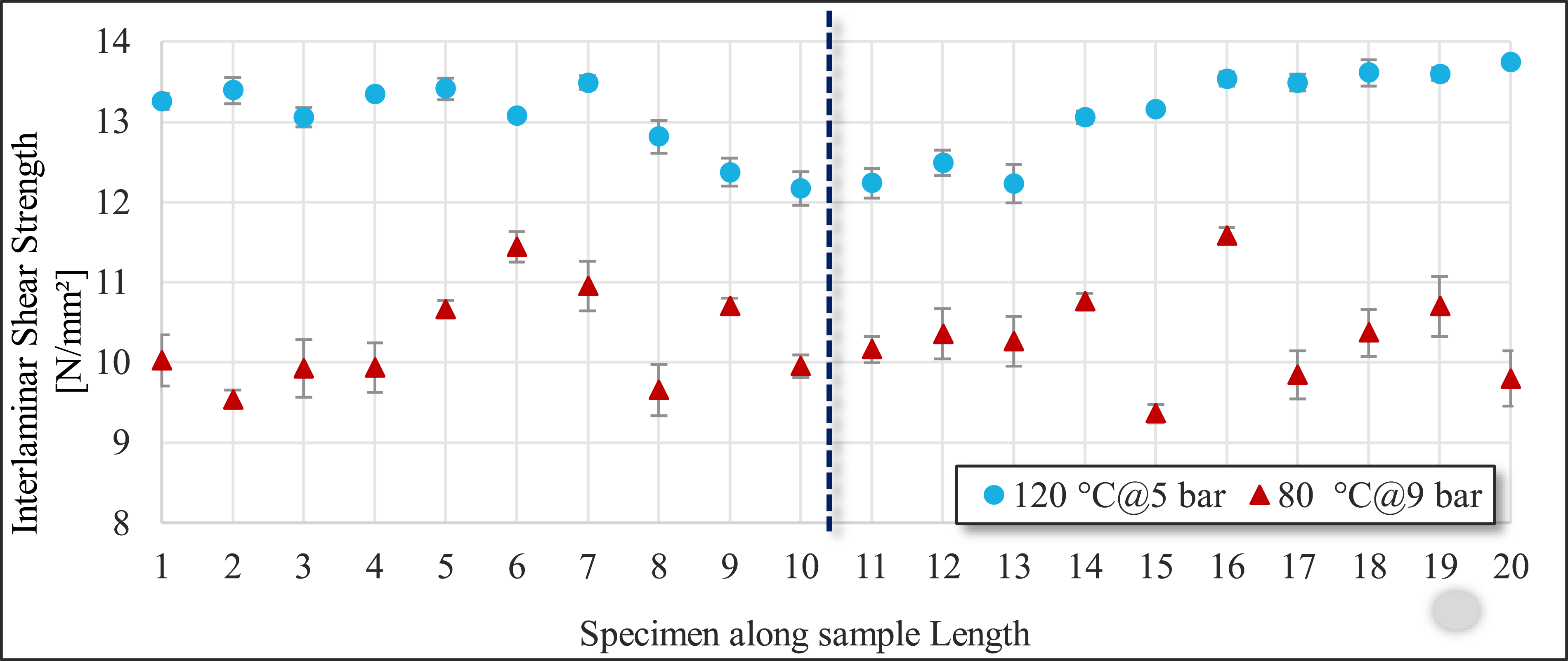
Like mold temperature, a linear trend can be observed across all nine samples when grouped based on injection pressure. Change in ILSS value with respect to injection pressure can be possibly related to two factors, i.e., fill time and fiber deformation near injection area. Fill time is the time recorded when resin enters the mold and spotted at the outlet vents for first time. Figure 9 shows the fill time recorded for the samples with respect to injection pressure and mold temperature. The data is averaged based on three samples for each case. The sample with the longest fill time of 58 sec has an ILSS value of 11.4 MPa, which is 15 % less than the maximum ILSS value recorded for a sample that has a fill time of 52 sec. However, sample with shortest fill time of 43 sec has an ILSS value of 11.4 MPa that is same ILSS value of the sample with longest fill time. Based on this statistical analysis, a proper relation could not be concluded on the fill time. Another factor that depends on the injection pressure is fiber deformation that occurs near injection area. To check this influence factor, the ILSS value across each sample’s length was investigated. Three different trends were observed based on this analysis. The first noticeable factor is that for all samples, the ILSS value near the injection area is lowest, that lies between specimen 10 and specimen 11. The second notable factor is the standard deviation near the injection zone is high in comparison with the end specimens of the sample, which implies that the values near the injection zone are inconsistent. The third notable factor is that the ILSS value across the sample tends to decrease, and the standard deviation tends to increase with decrease in mold temperature. Figure 10 shows the ILSS value recorded across the two samples that had maximum ILSS value and minimum ILSS value. The values are based on three samples for each location and standard deviation is recorded as the error. Based on these data, it was concluded that a pressure of 5 bar and a mold temperature of 120°C for current geometry and mold design is suitable based on ILLS property. Fill time of samples with respect to injection pressure. ILSS values across sample length based on three specimens averaged for data point.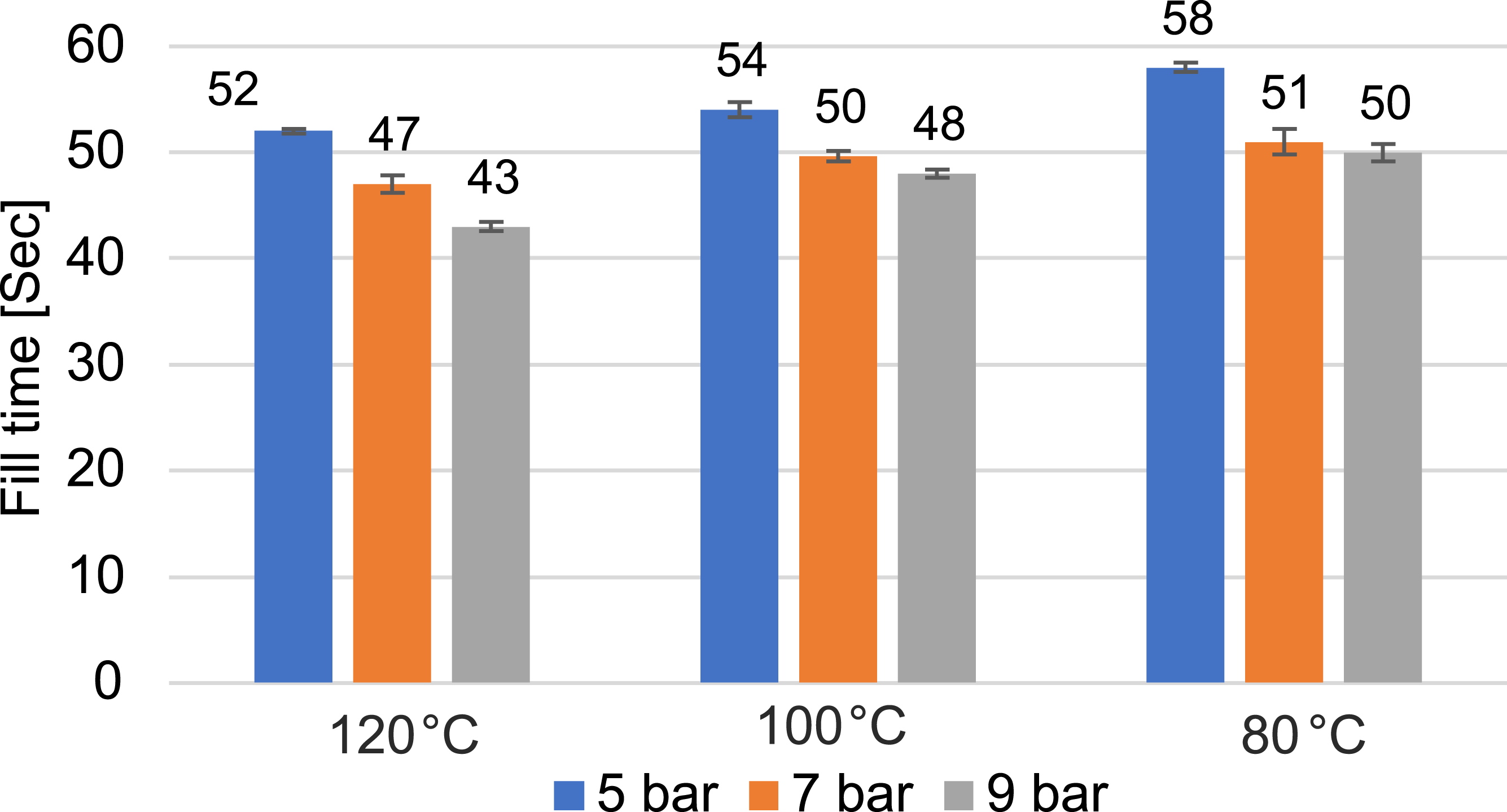
Similarly, the interface-modified samples were tested, and the results are presented in Figure 11. A significant increase of approximately 40 % in ILSS was observed when both sandblasting and glass fleece were used in combination, compared to the baseline sample without any modifications. When comparing the effects of glass fleece and sandblasting separately, the glass fleece-modified sample showed a 33 % increase in ILSS, while the sandblasting-only approach resulted in a 14 % increase, both relative to the unmodified sample. The increase in ILSS for the sandblasted sample can be attributed to improved mechanical interlocking between the steel and CFRP surfaces due to the roughened texture. In the case of glass fleece modification, the higher ILSS is likely due to the increased resin content at the interface, which improves adhesion. The fiber content in the glass fleece sample is 51 % (46 % CF + 5 % GF), lower than the 55 % fiber content (all CF) in both the unmodified and sandblasted samples. This reduction in fiber content is due to the glass fleece layer replacing part of the CFRP, which may also contribute to reduced galvanic corrosion at the metal-composite interface. ILSS results of interface samples with same production parameter.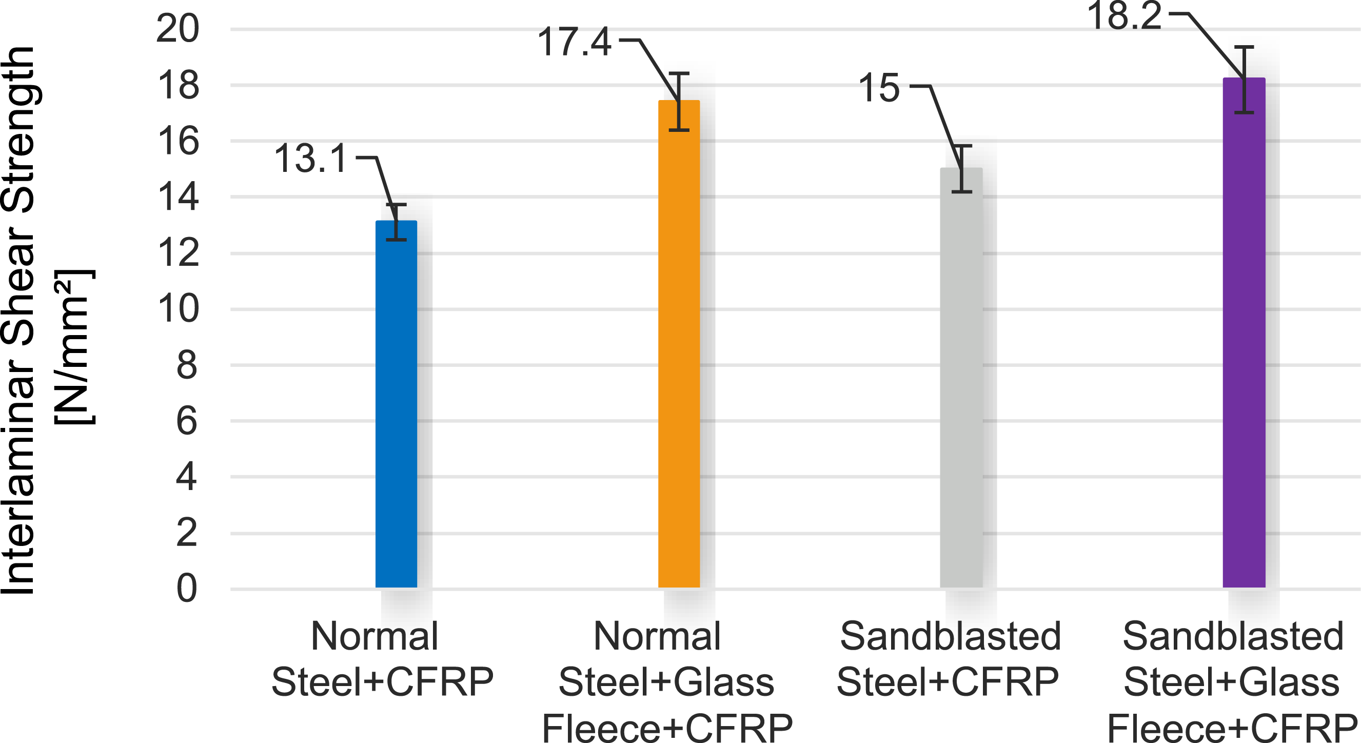
In conclusion, the combination of sandblasting and glass fleece significantly improves the ILSS, demonstrating the effectiveness of optimizing both mechanical interlocking and resin-rich interfaces for enhancing the performance of CFRP-steel hybrid structures. Building on these findings, further investigations were conducted to assess the behavior of the hybrid components under compression and torsion tests. The compression tests were designed to evaluate the energy absorption capacity of hybrid structures, which is critical for applications requiring high impact resistance or crashworthiness. By analyzing the hybrid components to absorb and dissipate energy, the study aimed to provide insights into their performance under dynamic loading conditions. Additionally, torsion tests were performed to evaluate the shear stress distribution and behavior under rotational loads, further assessing the structural integrity and mechanical performance of the components under torsional stress. These tests were conducted on two types of samples: the first being a baseline sample with an unmodified interface, and the second incorporating both sandblasting and glass fleece modifications. A steel-only sample was also included as a reference to compare the behavior of the hybrid structures against a traditional material under similar loading conditions.
Compression test
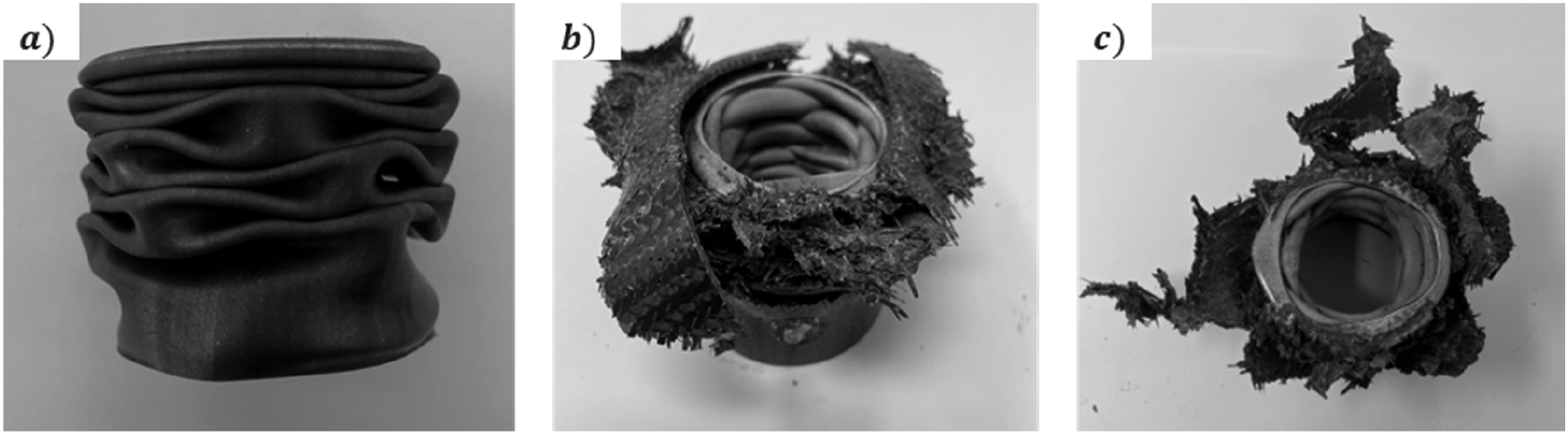
Compression tests were conducted using a servo motor spindle press capable of applying up to 300 kN of force. The samples, originally 320 mm in length, were cut down to 150 mm using a saw machine to ensure consistency. For each test, the same part of the sample, relative to the mold marking, was consistently positioned in the press, with the center of the sample always aligned with the moving part of the press, as illustrated in Figure 12. A specialized load cell was installed on the press to accurately measure both displacement and corresponding forces. The test speed was set to 5 mm/min, and samples were compressed until they were reduced by 90 – 100 mm of their length. Two types of samples were selected for the compression tests based on the interface study. The first, referred to as the normal hybrid sample, consisted of unmodified steel and six layers of CFRP. The second, known as the modified hybrid sample, had sandblasted steel combined with a glass fleece layer and five layers of CFRP. Additionally, a steel tube without CFRP was tested as a reference. The steel tube exhibited buckling and diamond buckling deformation modes (Figure 13(a)), while the hybrid shafts displayed diamond buckling along with shear cracking and wrinkling (Figure 13(b)). In addition, a common observation across all hybrid samples was the complete debonding of the steel and CFRP. Compression test setup of Hybrid shafts. Samples after compression test (a) Steel; (b) Normal Steel + CFRP and (c) Sandblasted Steel + Glass Fleece + CFRP.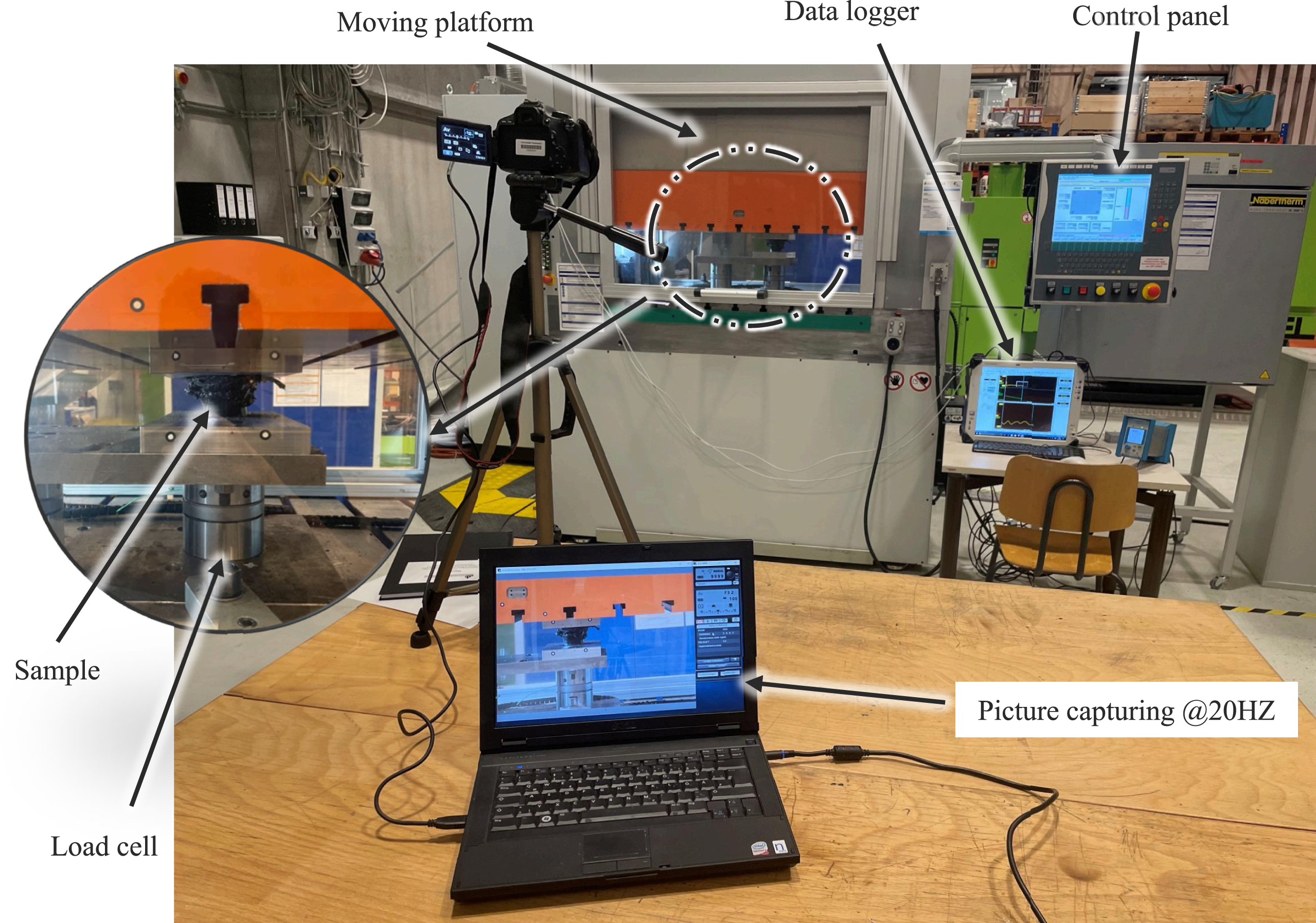
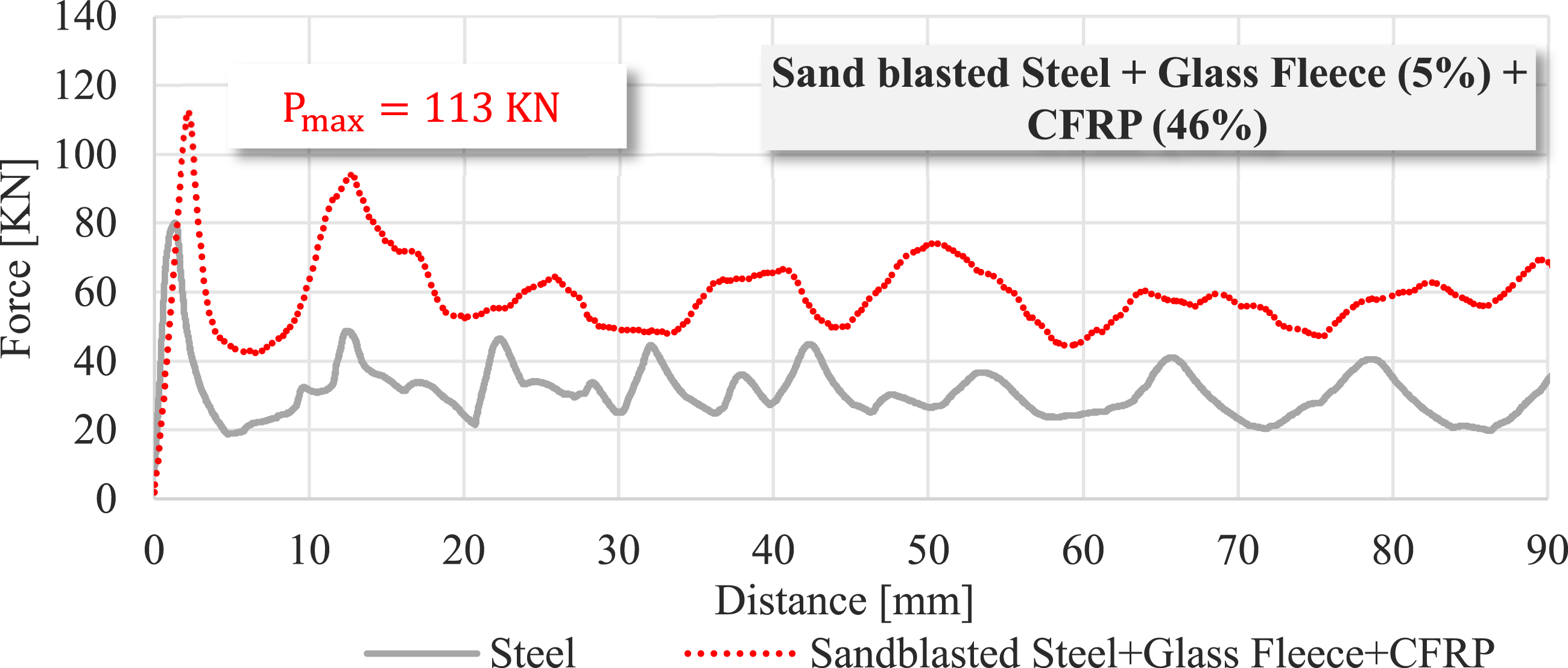
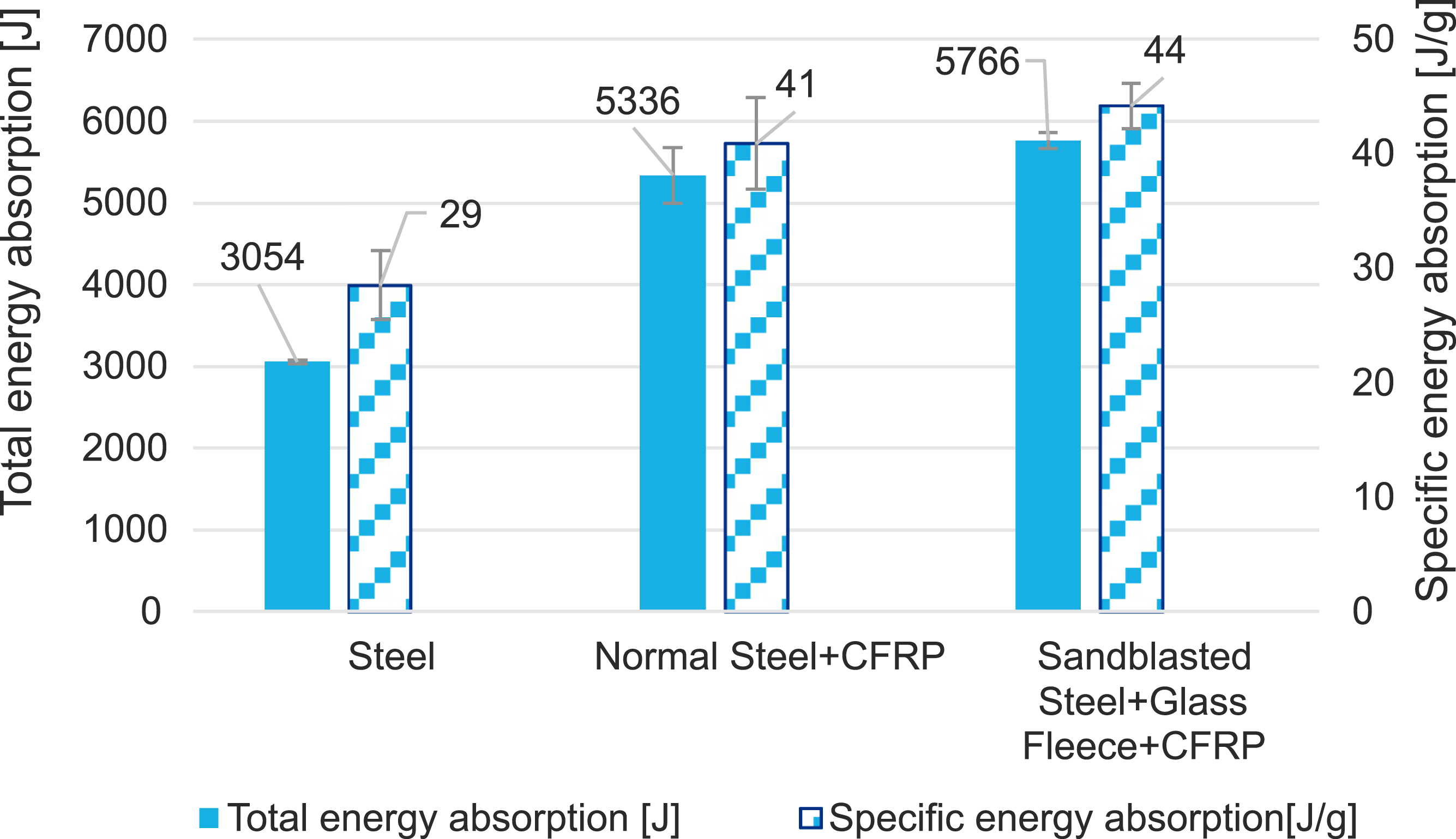
In terms of peak force, the hybrid tubes outperformed the steel reference tube, showing a 60 % increase in peak force. The average peak force for the hybrid samples increased by 88 % compared to the steel tube. The normal hybrid sample recorded a maximum peak force of 120 kN, while the modified hybrid sample achieved a slightly lower peak force of 113 kN, representing a 6 % decrease. However, the average force for the modified sample was 64 kN, which is 8 % higher than the normal sample’s mean force of 59 kN. Figures 14 and 15 shows the forces versus distance recorded during the compression test. Compression results of interface sample (Normal steel + CFRP) with respect to steel tube. Compression results of interface sample (Sandblasted steel + Glass Fleece + CFRP) with respect to steel tube.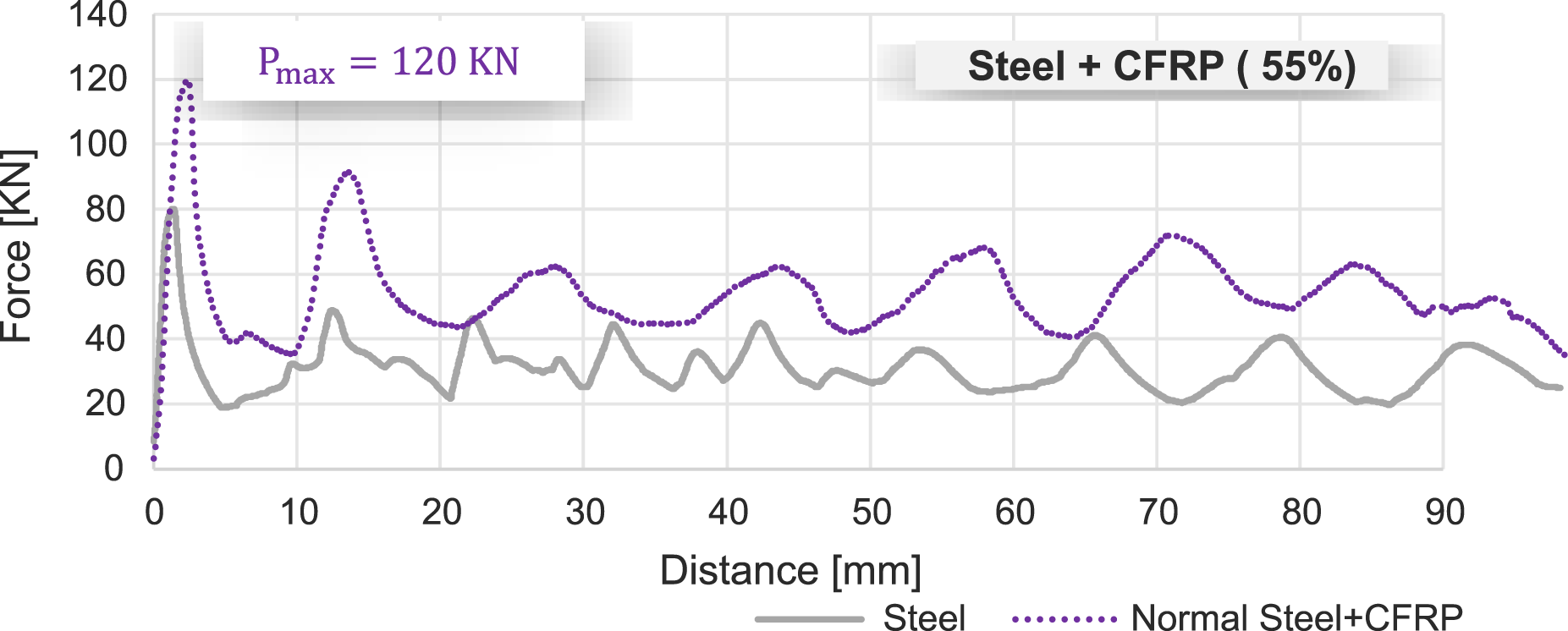
Key performance metrics for these compression tests were energy absorption and specific energy absorption, both of which are calculated using equation (3) and equation (4) that are plotted in Figure 16. Where EA is energy absorption, Total energy absorption and specific energy absorption of interface samples with respect to steel tube.

Torsion test
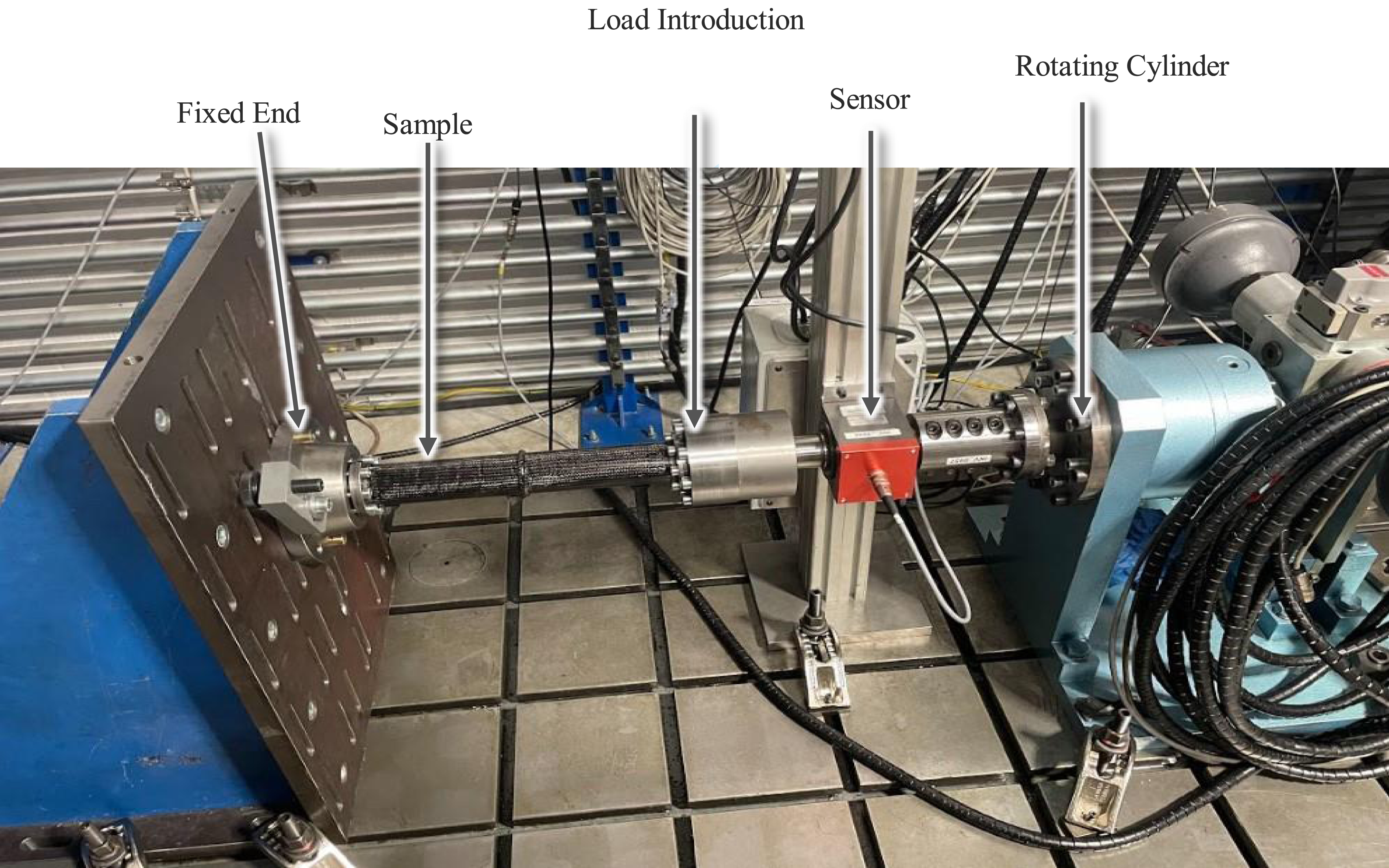
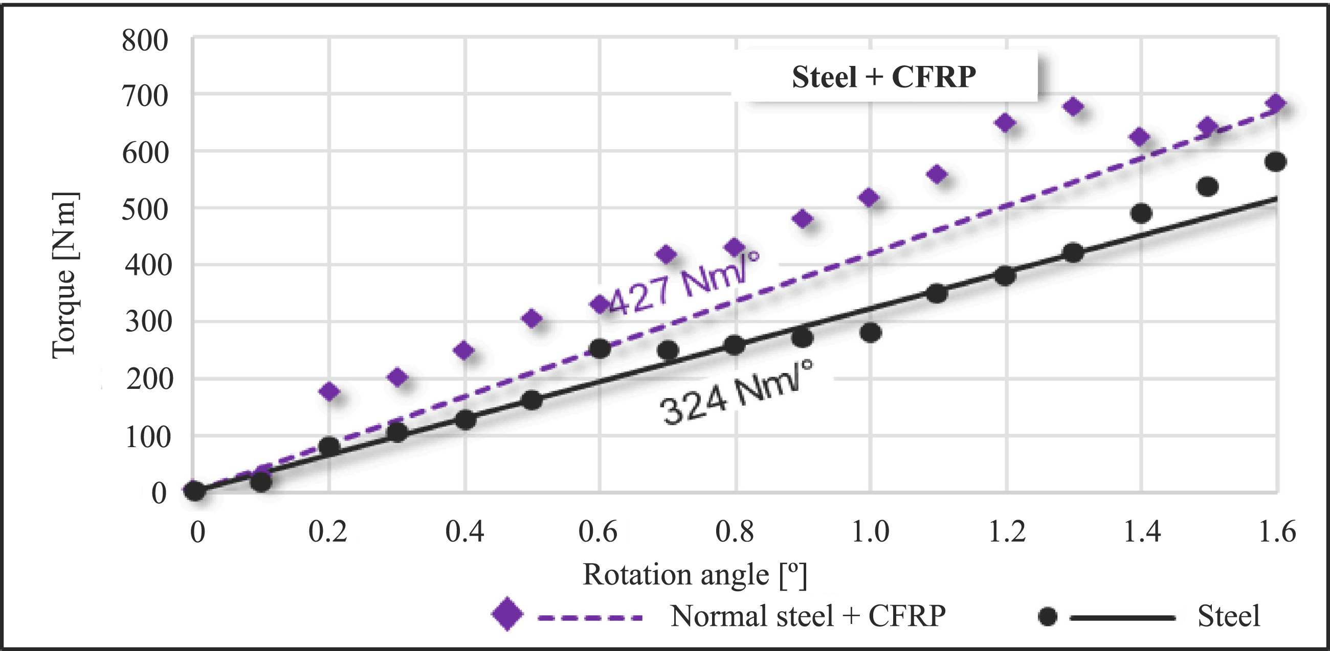
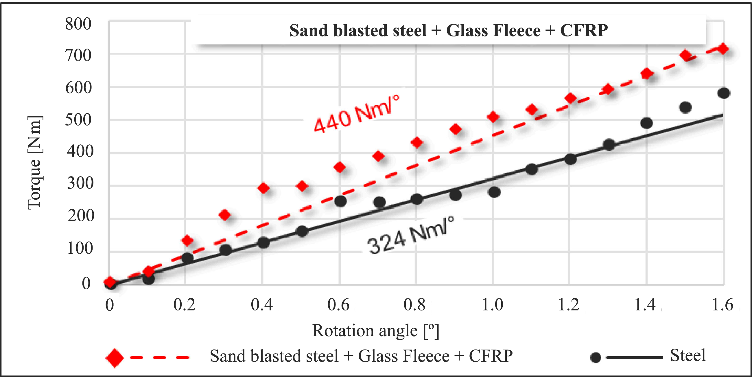
The torsional stiffness of the hybrid sample was determined using torsion setup based on the real load situation. A hydraulic rotary cylinder based on the double vane principle was used to introduce the torsional moment on the test samples. These valves can generate a torque of ±1000 Nm at a torsion angle of ±50°. The structure of the torsion test setup consists of rotating cylinder equipped with an angle of rotation and torque sensor. The clamps and load introduction are connected to the test specimen by means of a force-fit with the aid of annular springs as shown in Figure 17. The left side of the samples are fixed, whereas the right side of the samples is subjected to twist which is controlled by the sensors and the cylindrical values. Quasi-static tests were performed at 5°/min, for both normal and modified sample and data was recorded as shown in Figures 18 and 19. The points represent the data values recorded, and the line represents trend line. Torsional stiffness values of both hybrid samples are same with a small deviation of 3 % in their value i.e., normal hybrid samples had a torsion stiffness of 427 Nm/deg., whereas modified samples had a torsion stiffness of 440 Nm/deg. This indicates that interface modifications, such as sandblasting or the inclusion of glass fleece, have negligible influence on the torsional stiffness of the hybrid structures. For comparison, a reference torsion test was conducted on a steel tube without any CFRP reinforcement. The torsional stiffness recorded for the steel sample was 324 Nm/deg., which is 35 % lower than the hybrid samples. To validate the experimental findings, the torsional stiffness of the steel tube was calculated using equation (5) and equation (6). Where K is the torsional stiffness (Nm/rad); G is shear modulus (Pa); L is Length (m); J is polar moment of inertia (m4); D is outer diameter (m) and d is inner diameter (m). The torsional stiffness calculated for the steel tube was 18,488 Nm/rad, which can be equated to 323 Nm/deg. The input values used to calculate torsional stiffness are, polar moment of inertia of 92,440 mm4; Shear modulus of 70 GPa. In conclusion, while interface modifications did not significantly affect the torsional stiffness of the hybrid samples, the overall performance of the hybrid structures in torsion far exceeded that of the steel tube, demonstrating the superior mechanical properties imparted by the CFRP reinforcement. This makes the hybrid structures more suitable for applications requiring high torsional rigidity. Torsion test setup for interface samples. Torsion results of Normal sample (Normal steel + CFRP) with respect to steel tube. Torsion results of modified sample (Sandblasted steel + Glass Fleece + CFRP) with respect to steel tube.

CT investigation
As the next step in the study, a non-destructive test was performed using CT scanning to investigate the porosity within the CFRP-steel hybrid samples. CT scanning was selected due to its ability to provide high-resolution 3D models of internal structures without damaging the samples, making it ideal for detailed porosity analysis. The CT scan was conducted using a x|cube 225 device from GE, equipped with VG Studio Max 2022.1 software for the reconstruction and analysis of 3D models. The scans were performed at a voltage of 200 kV and a current of 2 mA. The X-ray gun used had a focus diameter of 0.4 mm, with an exposure time of 100 ms. To filter out weaker X-rays, a 2 mm copper filter was applied. The CT scan consisted of 1440 rotational steps to ensure optimal reconstruction of the 3D model. Based on the CT models, the total porosity in the hybrid samples was calculated to be 2.47 %, with a standard deviation of 0.04. The observed pore diameters ranged from 0.03 mm to 2.01 mm. Notably, most of the porosity was concentrated near the interface between the steel and CFRP layers, as shown in Figure 20. This suggests that factors such as resin flow or bonding processes may need further refinement to reduce void formation. Identifying porosity at the interface is critical, as it can negatively impact mechanical properties like shear strength and fatigue resistance. These results demonstrate that further optimization of the interface, through improved bonding techniques or material modifications, could enhance the overall structural integrity and reduce porosity in key areas. Pores distribution in Hybrid sample.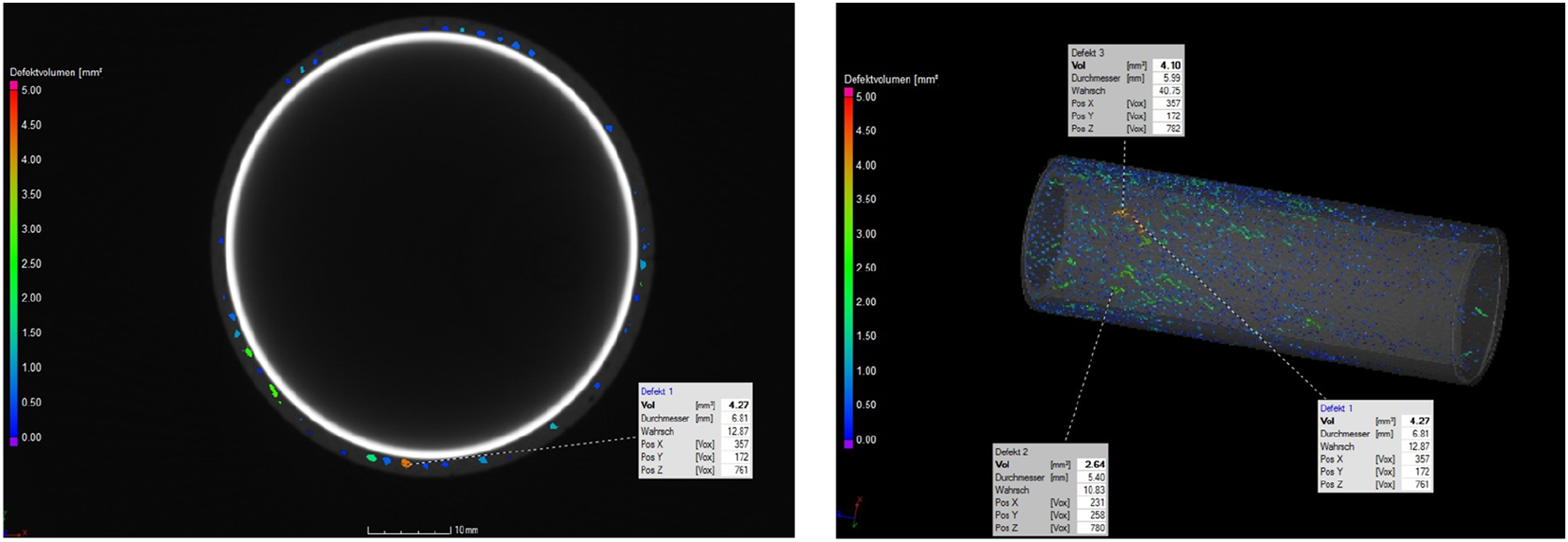
Conclusions
This study investigated the development and mechanical characterization of CFRP-steel hybrid structures produced via Resin Transfer Molding (RTM) with vacuum assistance. The influence of key process parameters, including injection pressure, mold temperature, and interface modifications, was evaluated in terms of interlaminar shear strength (ILSS), compression performance, torsional stiffness, and porosity. Optimization of the RTM process revealed that an injection pressure of 5 bar and a mold temperature of 120°C resulted in the highest ILSS values. This was attributed to better resin flow and fiber wetting due to lower viscosity at elevated temperatures. Furthermore, interface modifications combining sandblasting of the steel surface and the inclusion of glass fleece improved ILSS by 40 %, enhancing mechanical interlocking and increasing resin content at the interface. Compression testing showed that hybrid structures exhibited 60 % higher peak force, and 89 % greater specific energy absorption compared to traditional steel tubes. Torsional stiffness testing demonstrated that hybrid samples provided a 35 % improvement in stiffness over steel tubes, though interface modifications had minimal effect on torsional rigidity, suggesting that CFRP layers primarily contribute to increased torsional strength. Computed tomography (CT) scanning revealed that most of the porosity was concentrated near the interface, with an average porosity of 2.47 % and pore sizes ranging from 0.03 mm to 2.01 mm. This highlights a need for further refinement of the resin flow and bonding processes to minimize porosity at critical interfaces, thus improving overall structural integrity and fatigue resistance.
In conclusion, CFRP-steel hybrid structures present a highly effective alternative to traditional metal components, offering significant advantages in weight reduction, energy absorption, and torsional stiffness without sacrificing mechanical performance. The findings of this study provide a solid foundation for further optimization of hybrid structures, with a focus on reducing porosity and improving interfacial properties to enhance durability and performance in automotive and aerospace applications.
Footnotes
Acknowledgments
The authors would like to express their gratitude to the University of Paderborn for providing the research facilities and resources necessary for the successful completion of this study. Special thanks are extended to the technicians at LiA chair, for their invaluable technical support and assistance throughout the experimental phase of this research. Without their expertise and contributions, this work would not have been possible.
Declaration of conflicting interests
The author(s) declared no potential conflicts of interest with respect to the research, authorship, and/or publication of this article.
Funding
The author(s) received no financial support for the research, authorship, and/or publication of this article.
Data availability statement
All data generated or analyzed during this study are included in this published article