
Abstract
The present study is concerned with an experimental study into the effect of superimposed creep deformation, varying local fiber orientation distributions, and more complex multiaxial stress states on the fatigue of short fiber reinforced thermoplastics. The cross-interaction of these effects is a relevant feature in all fields of applications of short fiber composites since molding related variations of the local fiber orientation states cannot be avoided for injection molded structures. Long term loading will result in a combined occurrence of fatigue and creep and thus an interaction of the related effects. The study is based on a short glass fiber reinforced polyamide 66 as reference material which is a common material grade in many automotive applications. A basic characterization is performed by means of tensile and DMA experiments. Subsequently, creep and creep fatigue experiments are performed at ambient and elevated temperatures. In order to include the effects of locally varying fiber orientation situations and locally multiaxial loading situations, the coupon experiments are complemented by experiments on breadboard specimens featuring notches, holes, and structural component related external geometries. Superimposed creep deformation might accelerate fatigue failure, however, for notched specimens might also result in an increased fatigue lifetime due to creep-induced stress relief at the notch roots. The results reveal that care has to be taken when transferring the results on idealized coupon specimens to generalized, realistic problems. The results also serve as a development and validation data base for a continuum damage mechanics material model presented in an oncoming contribution.
Introduction
Short fiber reinforced plastics with disordered microstructure are popular materials in many fields of modern lightweight construction. Advantageous features are a reasonable stiffness and strength obtained at a rather low specific weight. Furthermore, these materials can easily be processed by injection molding as a standard and well-established manufacturing process for polymeric materials. The injection molding process also enables the easy manufacturing of highly integrated components with complex shapes. These advantages motivate the use of short fiber reinforced composites as materials for many semi-structural parts in the transport sector and other technological fields.
For short fiber reinforced composites, the use of thermoplastic matrix systems is advantageous due to their superior mechanical and manufacturing properties, their capabilities for inherent structural damping and the enhanced possibilities for material recycling at the end-of-life for the respective components. Nevertheless, a disadvantage is their tendency towards creep deformation due to the limited cross-linking of their molecular microstructure.
In engineering applications, the durability and fatigue lifetime of short fiber reinforced polymers are usually assessed in terms of classical Wöhler-Miner type
As an alternative approach to the mentioned uniaxial approaches, a number of multiaxial stress-based approaches have been proposed. Bernasconi et al,
12
De Monte et al.
13
as well as Mortazavian and Fatemi
14
presented
The micromechanics of fatigue degradation and failure of fiber reinforced composites have been extensively studied21,22 and compiled, 23 by Talreja for unidirectionally fiber reinforced polymers. For short fiber composites, it has been shown that the main degradation and damage mechanism consists of debonding of the fiber and matrix interfaces for the fibers oriented perpendicular to the principal loading direction. The evolving micro defects then trigger the cracking of the matrix. This finding has been confirmed by Corbetta et al. 24 and especially in tomographic analyses by Arif et al, 25 identifying debonding and pore formation at the fiber ends as the leading damage mechanism for short fiber reinforced polymers.
All of the cited studies are directed to fatigue degradation and failure only whereas superimposed creep effects are neglected. Creep effects become relevant especially for short fiber reinforced polymers with thermoplastic matrix systems due to the limited cross-linking of their macromolecular microstructure. The effect has been reported e.g., by Perreux and Joseph,
26
in a study on the fatigue of tubular specimens under biaxial loads. It is relevant, especially in tension-tension fatigue with positive
The present study addresses the interaction of creep and fatigue in an experimental approach. The interaction is studied on coupon level using unnotched and notched specimens as well as on breadboard specimens with more complex geometry and loading conditions. It is found that the interaction of creep and fatigue might accelerate the damage accumulation. However, contradictory effects might occur at notches and other stress and strain concentrations where creep might cause a stress and strain relief.
Material and methods
Material and test specimens
The reference material investigated in the present contribution was a short glass fiber reinforced polyamide 66 material with a fiber content of
From the raw material, plane plates with dimensions of Coupon specimens. (a) Injection molded plate, (b) Test specimens.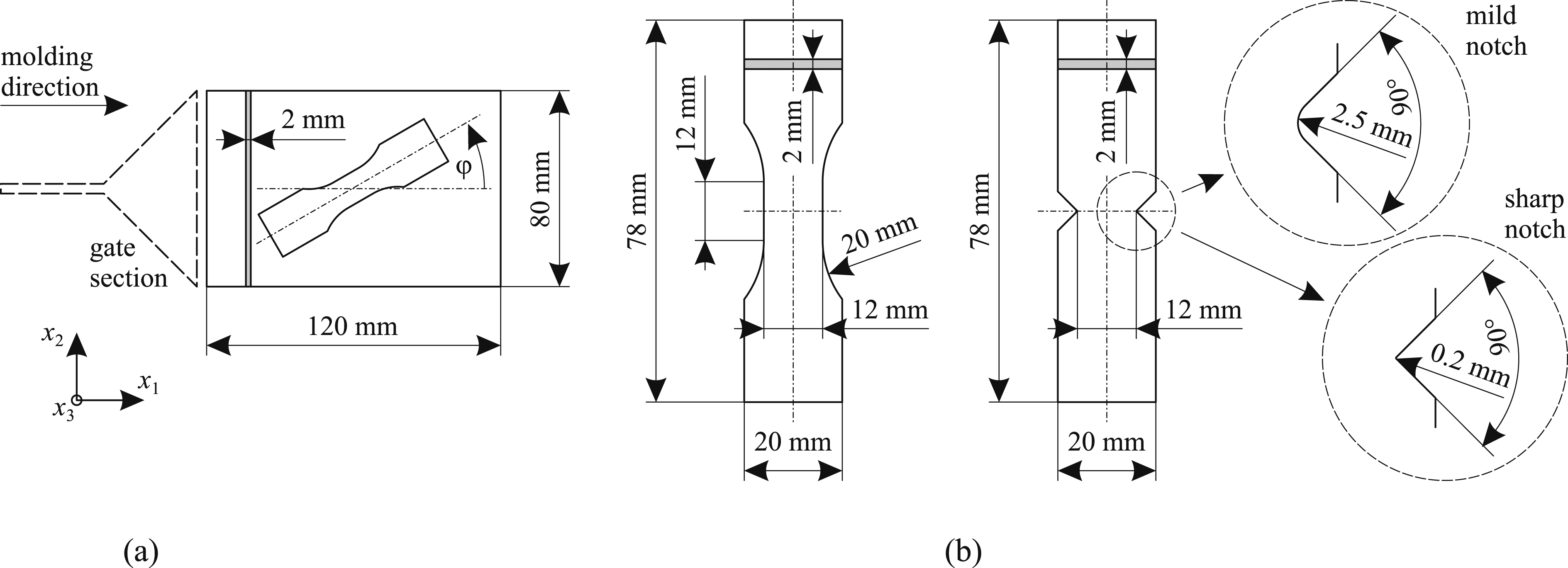
From the injection molded plates, plane test specimens according to Figure 1(b) were manufactured using waterjet cutting. Three different specimen geometries with and without notches were used. Both mild and sharp notches with notch root radii of
To secure comparable conditions and to prevent humidity effects due to the waterjet cutting process, the specimens were dried at
To investigate the effect of stress concentrations and general multiaxial loading conditions, three different types of breadboard specimens were considered. The first specimen type is the “T”-specimen according to Figure 2(a). The specimens were molded in either the longitudinal ( Breadboard specimens. (a) “T” specimen, (b) “Submarine” specimen, (c) “MultiTester” specimen.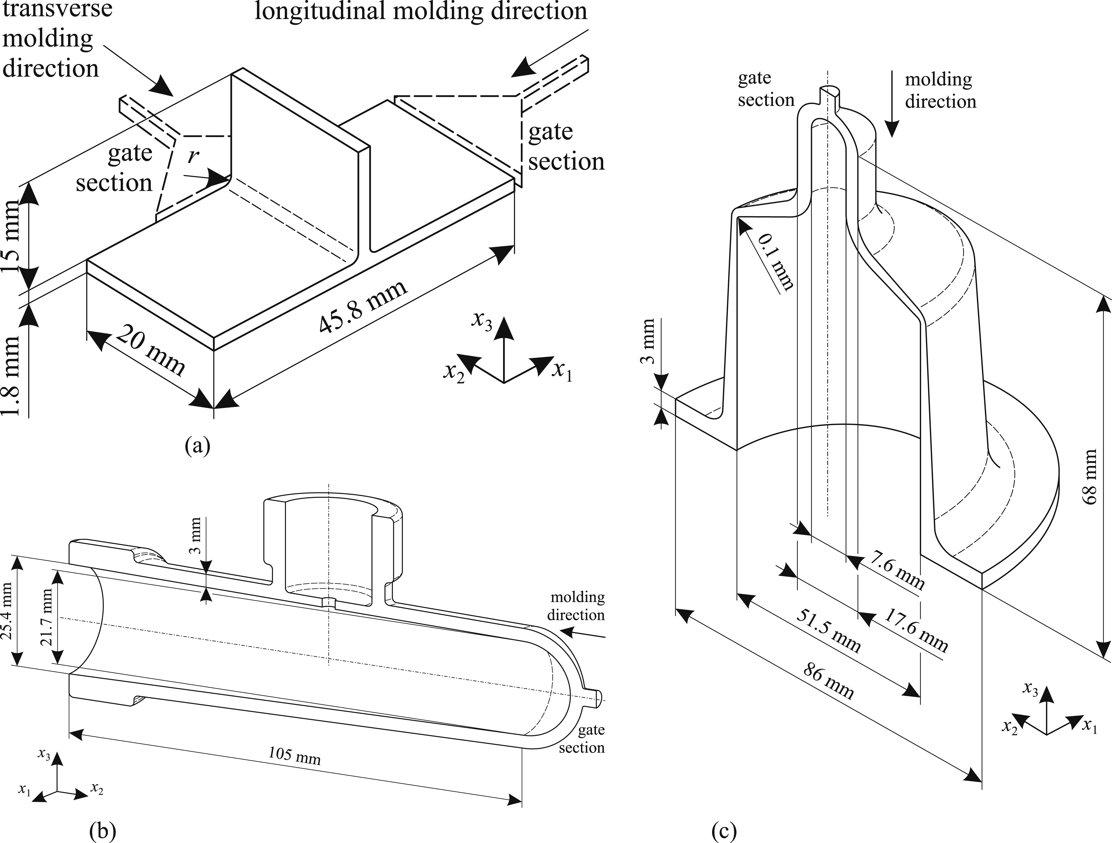
As specimens with even more complex geometry, “Submarine” and “MultiTester” specimens according to Figure 2(b) and (c) respectively were investigated. The specimens were injection molded from the right hand and top ends, respectively as sketched in Figure 2. The breadboard specimens were conditioned in a similar manner as the coupon specimens.
Test procedures
Microstructural investigation
Prior to mechanical testing the microstructure of the material has been investigated using both, metallographic sectioning in conjunction with optical microscopy and X-ray computed tomography. In-plane metallographic sections were taken from the center of three plates according to Figure 1(a) not used for specimen manufacture. Both near-surface locations and locations from the plate midplane were investigated. For an investigation of the fiber orientation distribution through the plate thickness, sections oriented in the
In addition, cuboidal specimens with
Basic mechanical characterization
A basic characterization of the mechanical response has been performed by tensile experiments on specimens oriented at angles of
For a preliminary characterization of the viscoelastic and damping properties, a dynamic mechanical analysis (DMA) was performed under three-point bending using a Netzsch DAM 242 E/1/G testing machine. The tests were performed at excitation frequencies of
Creep
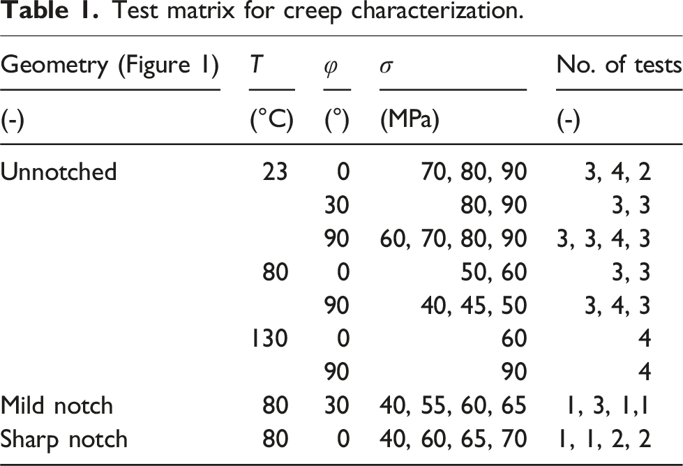
For evaluation of the creep response of the reference material, creep experiments were performed at constant temperature and constant applied stresses using a standard deadweight test rig in a climatic chamber to control temperature and humidity. The load levels were chosen related to the tensile strength of the material within the respective test direction. However, integer numbers were used rather than direct fractions of the ultimate tensile stresses, choosing identical creep loads for the different loading directions where feasible in order to provide comparable results.
Test matrix for creep characterization.
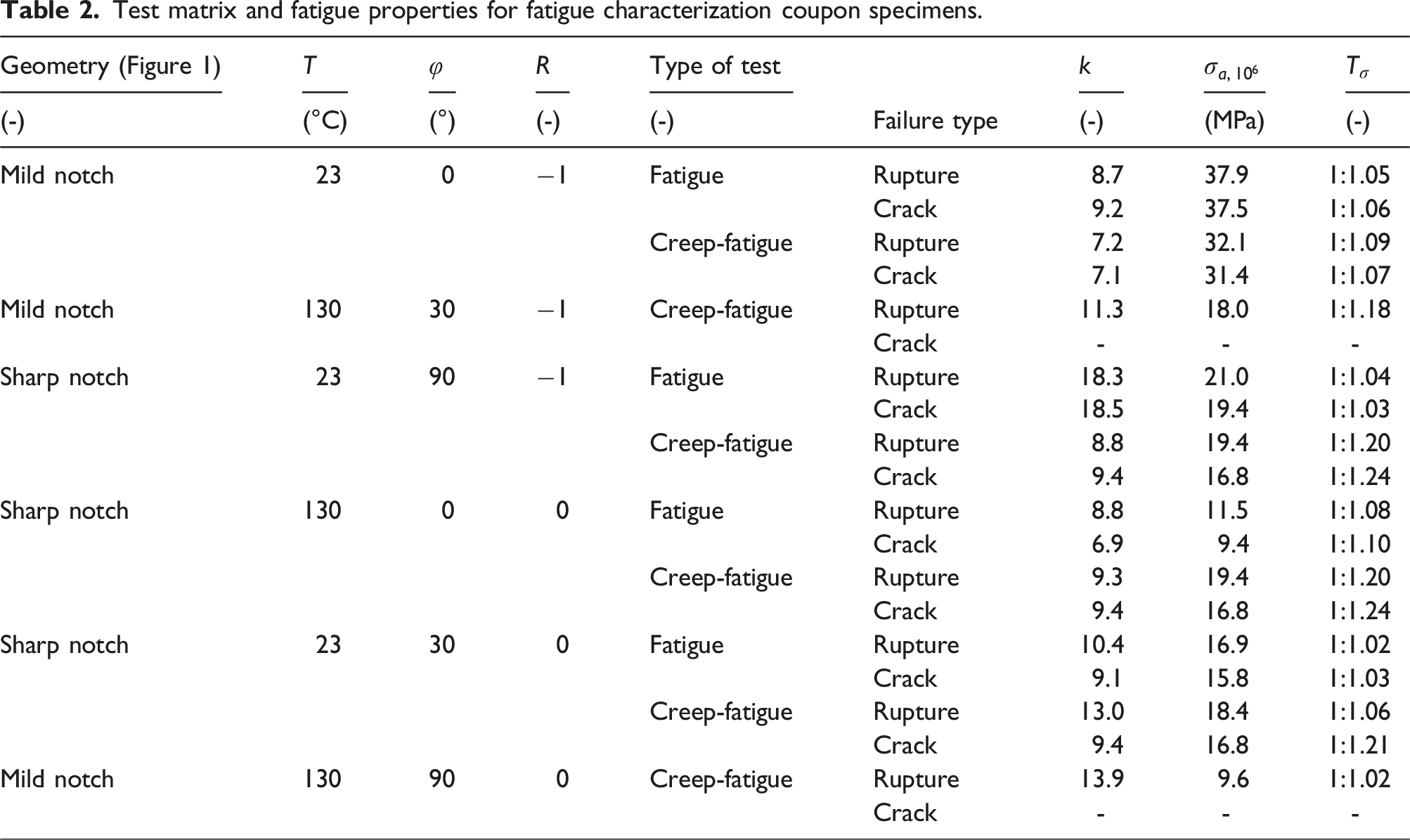
Fatigue and creep-fatigue
Test matrix and fatigue properties for fatigue characterization coupon specimens.
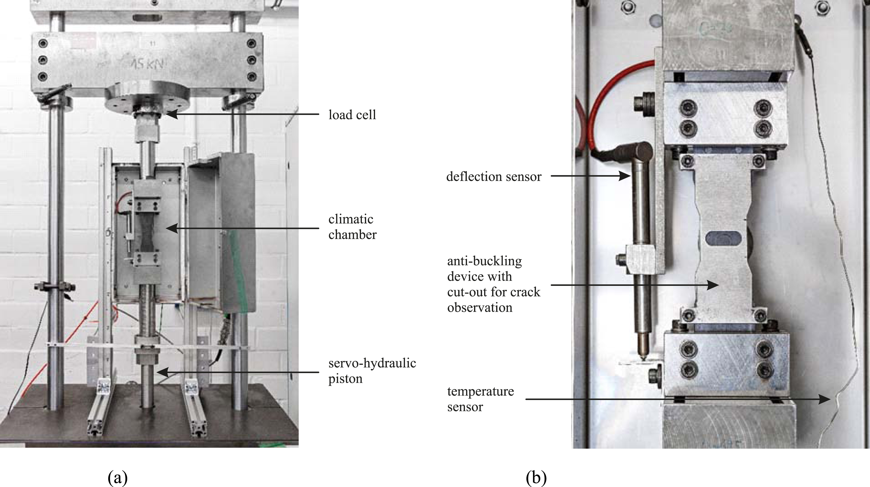
Generic test setup for fatigue experiments similar to those of the present study. (a)
In order to investigate the interaction between creep and fatigue damage, interrupted fatigue experiments were performed. In these experiments, harmonic sinusoidal loads were applied in blocks of
The fatigue and creep-fatigue experiments were performed on coupon specimens with mild and sharp notches according to Figure 1. All three test directions,
Fractography
To provide further details of the fracture mechanisms, the fracture surfaces of selected specimens were investigated in a fractographic analysis using scanning electron microscopy. For this purpose, the fracture surfaces were sputtered with a metallic coating of approximately
Fatigue under complex loading conditions
In order to assess the effects of more complex loading situations, breadboard specimens according to Figure 2 were tested. Three different types were considered. Different general specimen geometries being used in previous investigations were chosen. As generalization compared to the coupon specimens, geometries with different types of notches, cross-sectional variations, as well as general external geometries and loading conditions were considered.
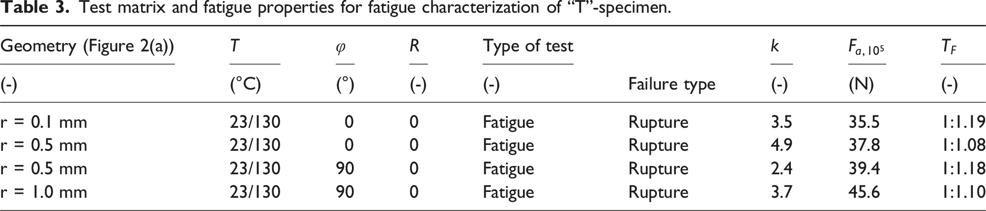
Test matrix and fatigue properties for fatigue characterization of “T”-specimen.
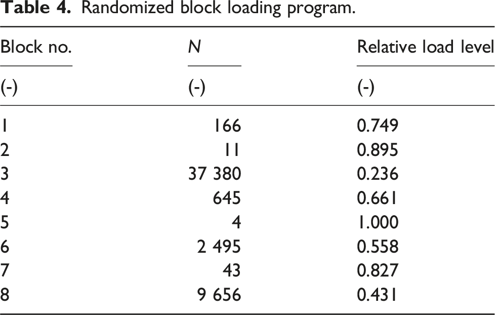
Randomized block loading program.

Test matrix and fatigue properties for fatigue characterization of “MultiTester” and “Submarine” specimens.
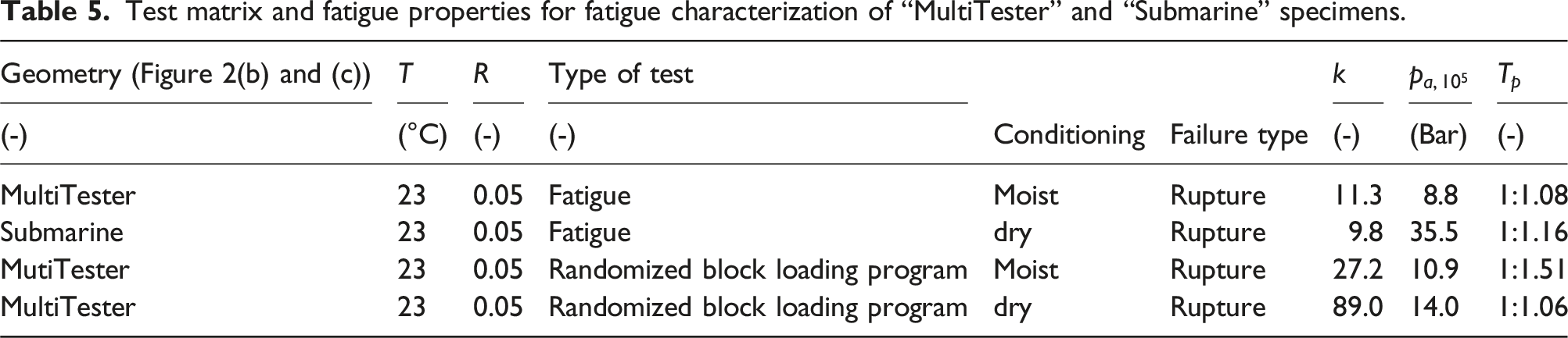
Further to the effect of complex loading conditions, the effect of humidity was examined in the experiments on the “MultiTester” specimens. For this purpose, a series of these specimens were conditioned in a wet environment in contrast to all other specimens being conditioned as described before. The different test conditions are compiled in Table 5.
In addition to the experimental investigations of the present study, the coupon and breadboard experiments also serve as development and validation data base for a damage mechanics material model accounting for short fiber composites presented in a companion paper (Abdul Hamid et al, 27 Spancken et al. 28 ).
Results
Microstructure
Selected results of the metallographic section investigation are presented in Figure 4, considering the in-plane fiber orientation distribution near the plate surface (Figure 4(a)) and in the specimen midplane (Figure 4(b)) as well as the transverse fiber orientation distribution (Figure 4(c)). No distinct differences are observed between the in-plane fiber orientation distribution in the specimen midplane and a plane near the plate surface. Consequently, only a slight formation of a central layer with a fiber orientation perpendicular to the flow direction ( Microstructural investigation. (a) In-plane section, near-surface position, (b) in-plane section, midplane, (c) transverse section, (d) transverse distribution of 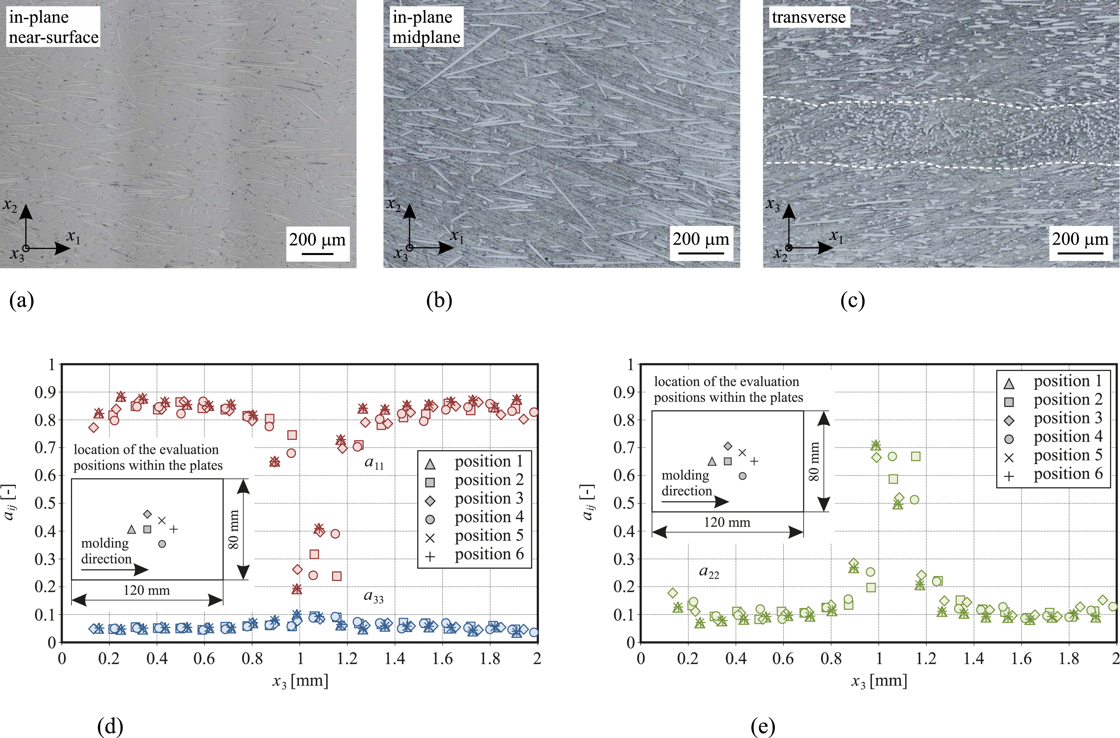
This result is confirmed by the results of the three-dimensional tomographic investigation. In Figure 4(d) and (e), the distribution of the main diagonal parameters
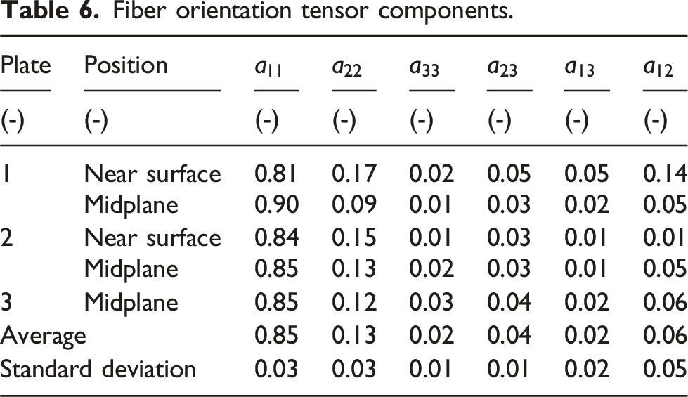
Fiber orientation tensor components.
Basic mechanical characterization
The results of the quasi-static tensile experiments are presented in Figure 5 for both, the Quasi-static tensile characterization. (a) Testing in 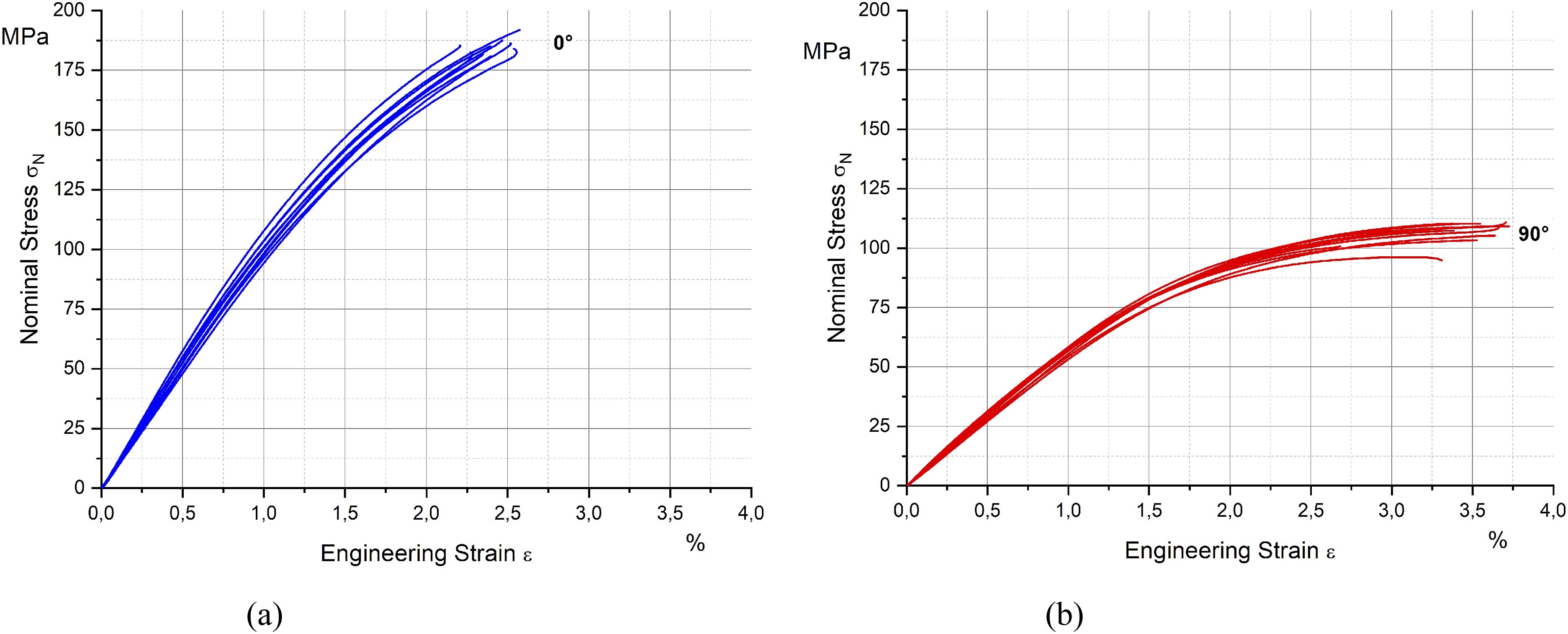
In Figure 6, the DMA test results for the storage and loss moduli Dynamic mechanical analysis. (a) Storage modulus, (b) loss modulus.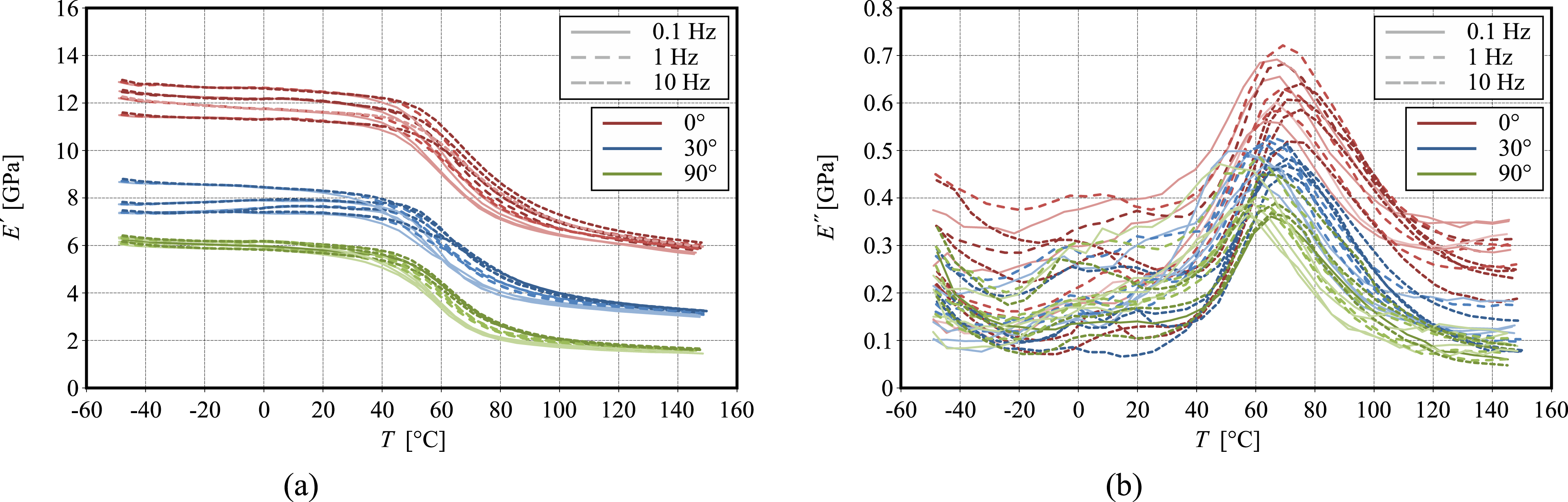
Creep
The creep curves obtained on unnotched specimens at ambient temperature are presented in Figure 7, considering test directions of Creep curves of unnotched specimens below, at, and beyond the glass transition. (a) Ambient temperature, test direction 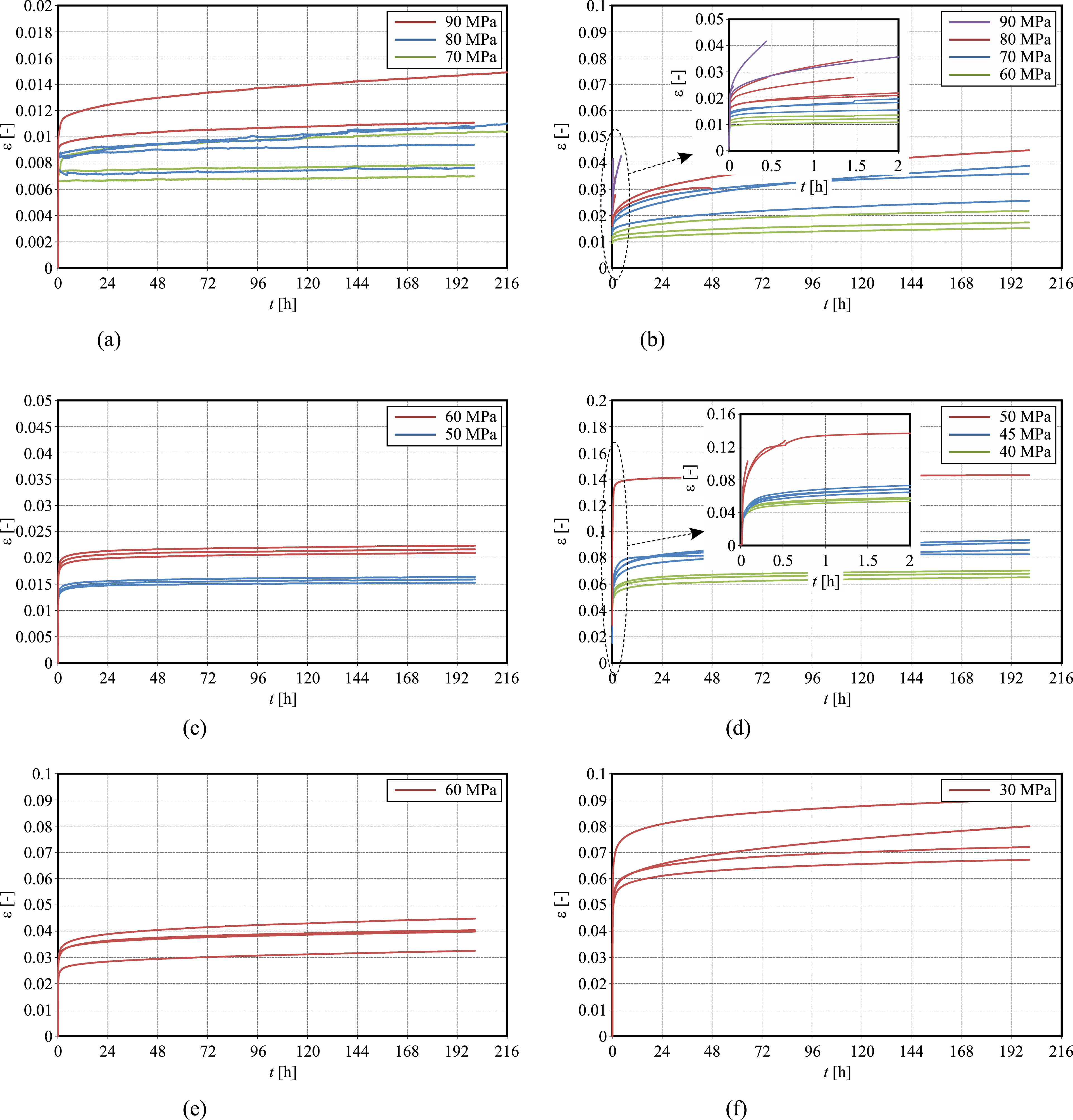
The creep response for a test direction of
The results of the creep experiments at
The creep results obtained at a test temperature of
Complementing the experiments on unnotched specimens, a limited number of experiments on notched specimens considering selected cases were performed. The results are presented in Figure 8(a) for mild notched specimens tested at an angle of Exemplary creep experiments on notched specimens at 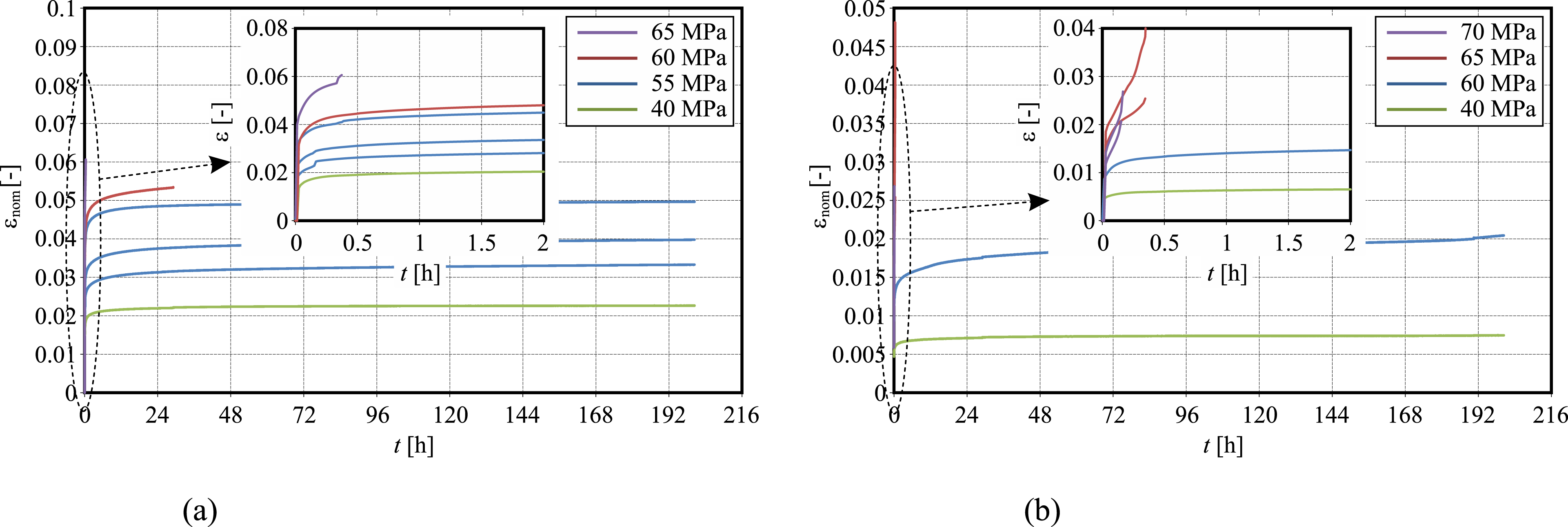
Fatigue and creep-fatigue
The results of the fatigue and creep-fatigue experiments on coupon specimens for the different conditions compiled in the test matrix in Table 2 are presented in Figure 9. The characteristic values of the Fatigue and creep-fatigue experiments. (a) Test direction 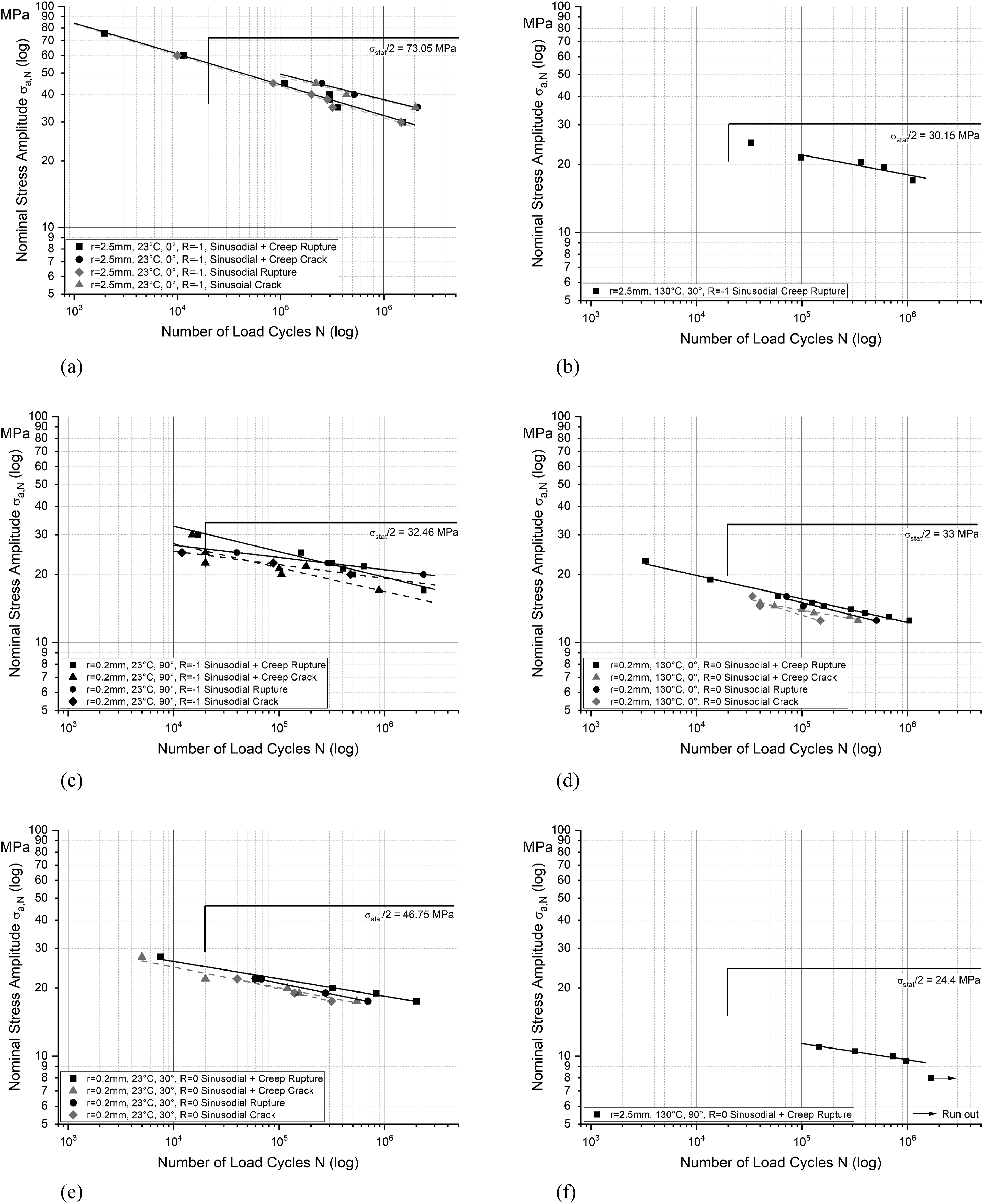
All 
By using the inclination 
Subsequently, any value of stress amplitudes concerning the number of load cycles can be calculated by
To evaluate survival probabilities and the scattering, the experiments of the 

With the parameter 

The scattering 
For the case of alternating fatigue loads applied in the fiber preference (
At a test direction of
The results for the fatigue experiments in the sharply notched specimen configuration are presented in Figure 9(c) to (e). For the specimens tested perpendicular to the fiber preference direction at ambient temperature and a load ratio of
Qualitatively similar results – although less distinct – are obtained in the experiments in
Fractography
In a first approach, the fracture surfaces of the ruptured creep specimens were investigated. Figure 10 presents the total fracture surface on the right side of a specimen tested perpendicular to the fiber preference direction at Creep fracture surface (unnotched, test direction 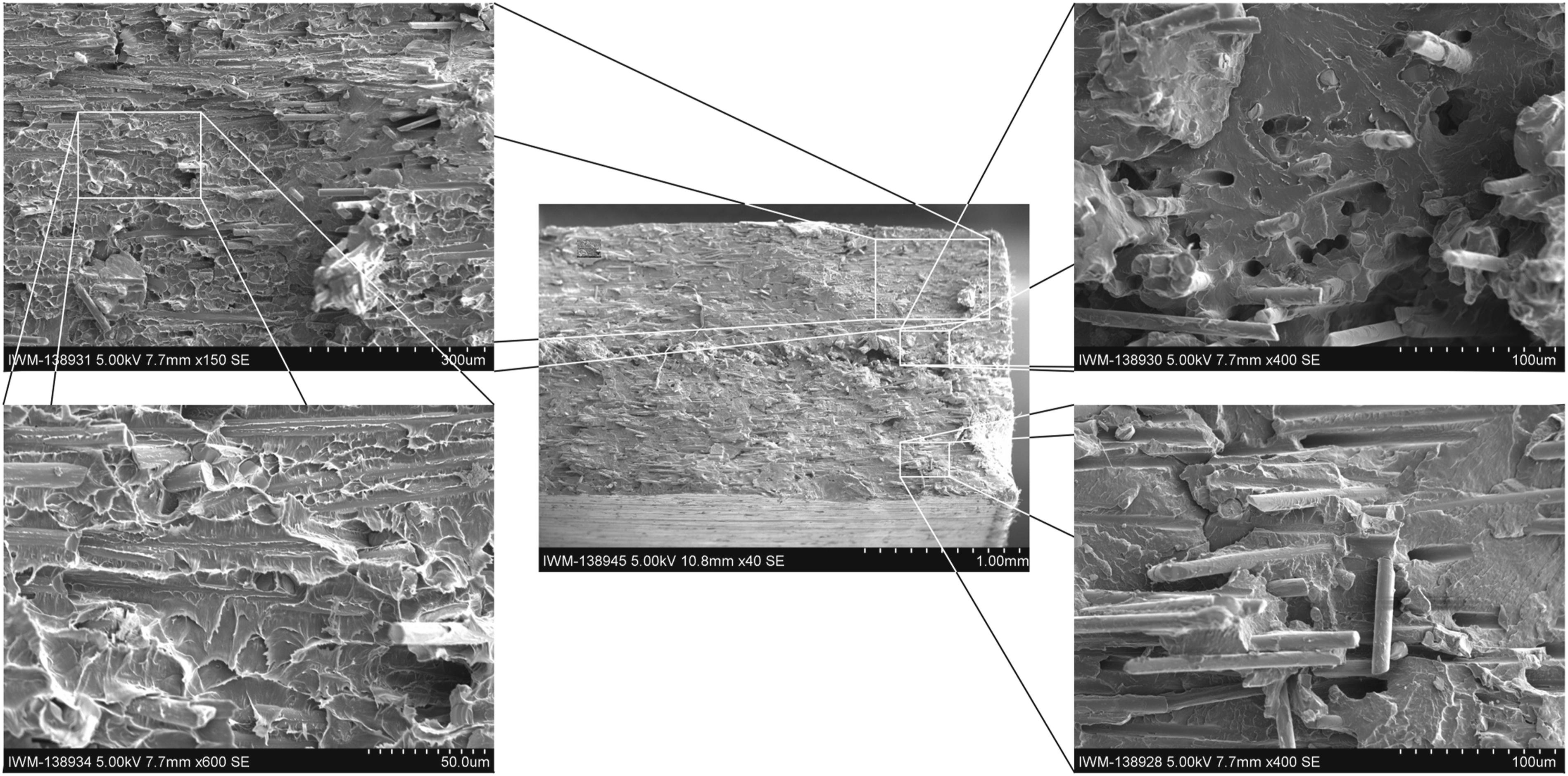
The matrix exhibits a mostly brittle fracture surface without relevant formation of ductile dimples. Due to the testing direction perpendicular to the fiber preference direction, most fibers are found within the fracture surface. To a large amount, rupture has occurred in an inter-fiber fracture mode with only a few visible fibers. In the – in the present material rather thin – central layer (see Figure 4) fibers are predominantly oriented normally to the fracture surface. Here, brittle matrix failure together with fiber pull-out is found to be the dominating failure mode. The fiber surfaces in most cases are free from matrix adherences, thus indicating fiber matrix interface failure as the most relevant microstructural failure mechanism. Together with the visible fiber pull-out, this finding indicates that void formation at the fiber ends might also play an important role in the damage and failure process, despite not being visible on the fracture surface. No evidence of fiber fracture during the specimen rupture is found. The visible fiber fracture surfaces are probably due to the fracture of the fibers during the manufacturing process.
Similar observations are made at the opposite end of the fracture surface. Nevertheless, the fracture surface on the left side in general exhibits a rougher appearance than on the right side presented in Figure 10. It is assumed that rupture was triggered in the smoother right side of the specimen whereas crack branching effects during crack propagation are assumed to have caused the rougher appearance of the fracture surface towards its left end.
The creep experiments in Section 3.3 indicate a different material response close to the glass transition temperature. For this reason, the fracture surface of a specimen oriented at Creep fracture surface (unnotched, test direction 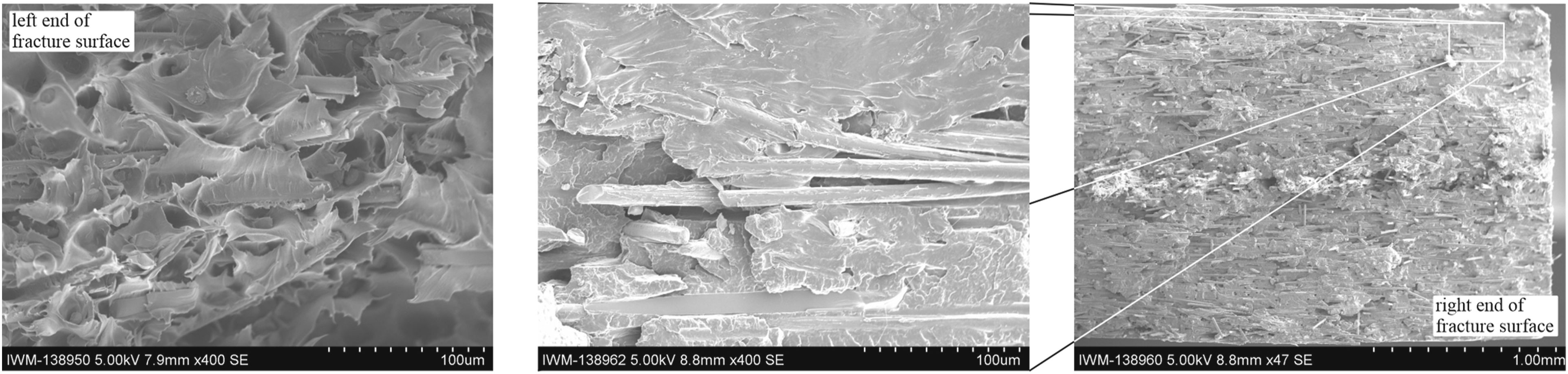
The fracture surface on the right side of the specimen – the side of the fracture initiation –indicates a brittle failure of the matrix together with fiber matrix interface failures, indicated by blank fiber surfaces without matrix adhesions. Already in this range, indications for crack branching are visible as in the case of the sub-surface crack in the detail from the right end of the fracture surface. In contrast to the observations on the specimen tested at ambient temperature, a predominantly ductile failure is observed at the opposite end of the fracture surface. Thus, a mixed failure mode with a brittle initiation but partly ductile propagation develops in the creep rupture at
A similar investigation has been performed for the specimens tested under fatigue loads. Figure 12 shows the left end of the fracture surface of a mildly notched specimen tested in Fatigue fracture surface (mild notch, test direction 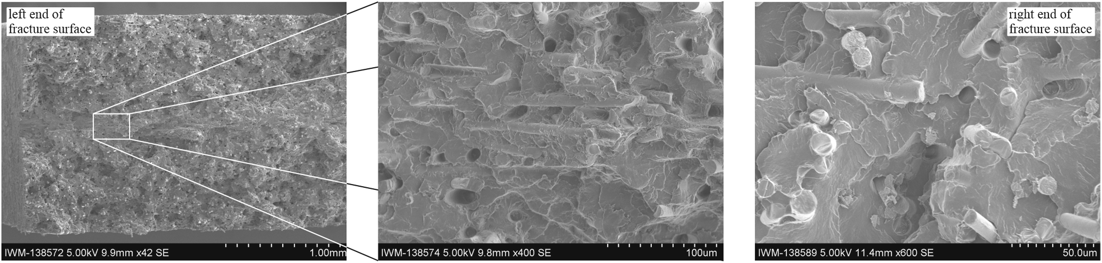
For comparison, the fracture surface of a specimen with mild notch tested under pure fatigue with Fatigue fracture surface (mild notch, test direction 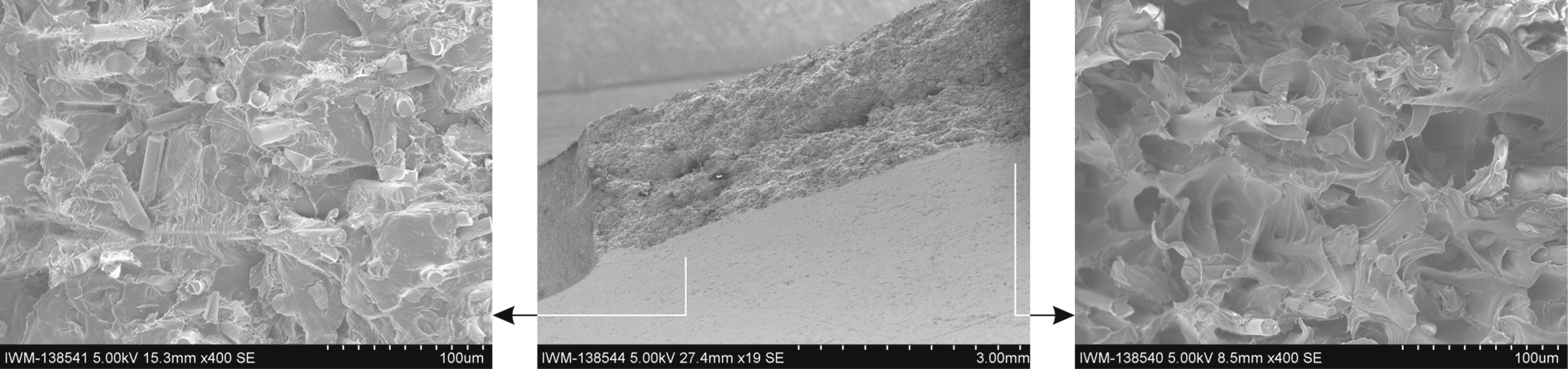
In order to assess the effect of the load ratio Fatigue fracture surface (sharp notch, test direction 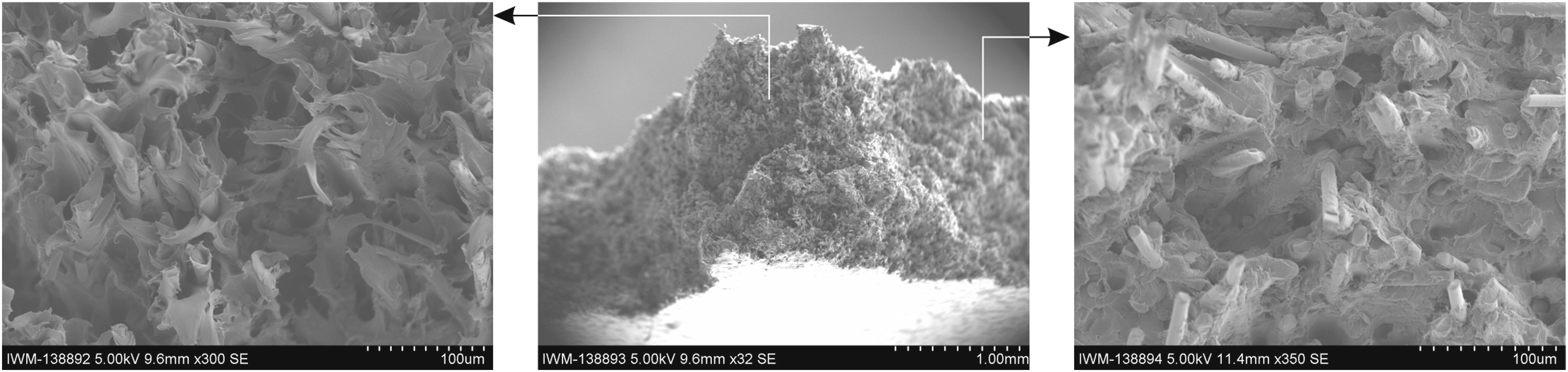
For a direct comparison, details of the fracture surfaces of specimens tested under creep, pure fatigue load, and creep-fatigue are presented in Figure 15. All specimens were tested at elevated temperature. Fatigue loads were applied as tension-tension fatigue with a load ratio of Fracture surfaces for different loading types.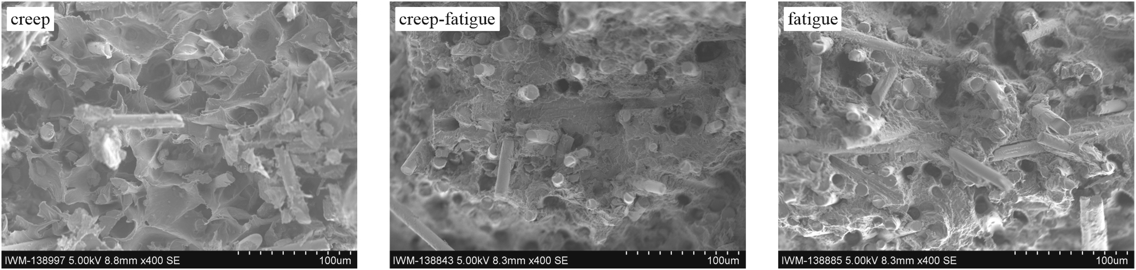
Fatigue under complex loading conditions
The results of the fatigue experiments on the “T”-specimens with intermediate change in the thermal conditions are presented in Figure 16(a) for all four specimen configurations considered. The characteristic values Fatigue under complex loading situations. (a) “T”-specimens, (b) “MultiTester”- and “Submarine” specimens.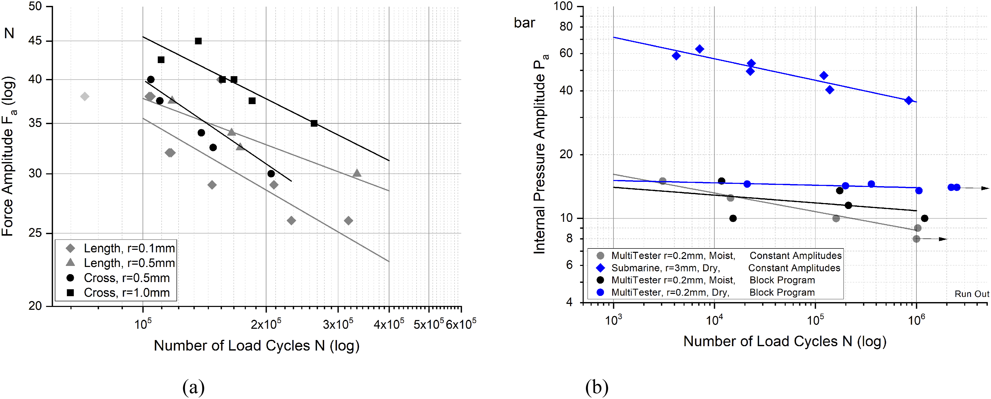
For all four test configurations,
The (structural component related)
Complementing the investigations of the present contribution, the experiments on the three types of breadboard specimens will serve as validation experiments for a continuum damage mechanics material model developed in an oncoming contribution (Abdul Hamid et al. 27 ).
Discussion
The results of the experimental investigation reveal a strong effect of the flow direction on the fiber orientation and thus the mechanical properties of the material, as to be expected. In this context, only a limited development of a layered structure as it would be usual for injection molded components is observed in the plates used for coupon specimen manufacture due to the special design of the gate section in the manufacture of the plates. Thus, the coupon specimens could be considered as specimens with a uniform fiber orientation distribution through the specimen thickness. In general, both stiffness and strength are found to correlate with the number of fibers oriented towards the loading direction. In this context, more pronounced nonlinearities are observed in the material response for 90° test orientation due to more pronounced matrix effects perpendicular to the fiber direction. Accordingly, the material response strongly depends on the flow direction during the molding process. This becomes obvious in the experiments on “T” specimens, where specimens with identical geometry were molded alternatively in two spatial directions.
The dynamic mechanical analysis revealed a distinct viscoelastic effect with significant loss moduli especially in the range of the glass transition temperature at approximately
The creep experiments featured a primary creep phase with decelerating creep rate with a subsequent secondary creep phase at an almost constant creep rate as expected. However, no tertiary creep phase with accelerating creep rate prior to creep rupture was observed in the experiments on unnotched specimens. Instead, creep rupture occurred in a sudden brittle failure mode without any preliminary indication. For the ruptured specimens, the failure strains were found in the same range as the failure strains in the quasi-static experiments. Nevertheless, in both cases, the failure strains depend on the fiber orientation state and the testing direction. This observation indicates a strain-driven failure mechanism.
Similar results were obtained in the experiments on notched specimens at elevated temperature, except for a minor development of a tertiary creep phase on specimen level prior to rupture. Nevertheless, the apparent tertiary creep is suspected to be related to a crack propagation process from one of the notch roots into the unnotched area rather than being a material creep effect. This observation is confirmed by the fractographic investigation which revealed a brittle failure mode in the crack initiation range of all specimens – whether notched or unnotched – whereas a mixed and ductile failure mode is observed on the fracture surfaces in the crack propagation ranges. A generally rougher appearance of the fracture surface in conjunction with breakouts gives evidence of a crack propagation process with crack branching induced by the fibrous microstructure, increasing the macroscopic fracture toughness further.
The crack propagation is observed to follow the fiber preference direction as far as possible and thus to occur in a matrix-dominated mode. For fiber orientation states and loading directions, where a failure in fiber direction is essential, a large amount of fiber pull-out is observed. In this context, the fibers are mostly found blank without matrix adhesions, indicating fiber matrix interface debonding as the leading micromechanical failure mode. In conjunction with the observed fiber pull-out, void formation at the fiber ends is also likely. No evidence of fiber breakage during the specimen rupture process is observed. Brittle failure surfaces on fibers are probably due to fiber breakages during the manufacturing process.
The creep curves feature a distinct scatter due to the disordered microstructure. The effect is found more pronounced in test directions other than the fiber preference direction, i.e., in the more matrix-dominated test directions due to lower creep constraint imposed by the fibers oriented in directions off the loading direction. In the range of the glass transition temperature, the scatter for the unnotched test configurations becomes much less pronounced. At the same time, secondary creep phases with rather low creep rates are observed even when creep strains in the range of the failure strain are reached. This effect could be caused by an easier local stress relief at stress concentrations on the microstructural level, making stress concentrations less severe and thus preventing them from triggering failure. For notched specimens, a distinct scatter is observed even close to the glass transition temperature due to the smaller size of the highly loaded (stressed and/or deformed) volume causing a much less pronounced self-averaging effect of the material.
The effect of crack propagation is also observed in the fatigue response. More pronounced differences between the
In the interaction of different deformation types, creep is found to have distinct, non-negligible effects on the fatigue resistance and lifetime of the material. The results indicate the simultaneous action of different and contradictory effects. Basically, intermediate creep phases – and thus also creep deformation developing during the high-stress phases of the cyclic fatigue loads – might accelerate the fatigue failure. The reason is the accumulation of additional damage due to the creep deformation. On the other hand, especially for sharply notched test configurations, creep deformation of the material results in stress relief in the stress concentrations at the notch roots. Thus, a stress redistribution to the surrounding area occurs, resulting in an increase in the highly loaded area at lower load levels and thus a partial relief of the notch effect. This effect is suitable for an apparent increase in the fatigue lifetime on the specimen level (although not on the material level in the rigorous sense). Consequently, a decrease in the fatigue lifetime is observed in the experiments on mild notched configurations with limited notch effect. On sharp notch test configurations, the opposite effects are observed with a partial increase in the fatigue lifetime of the specimen due to a creep-induced partial relief of the notch effect.
Regarding the local failure modes, no pronounced and systematic differences are observed considering creep, creep-fatigue, or pure fatigue loading conditions in the fractographic investigations. This finding confirms the observation that failure is triggered in a strain-driven mechanism with a similar, temperature and fiber orientation distribution dependent, failure strain for all loading types. In all cases, the
In the experiments on breadboard specimens, it is found that wet conditioning of the material results in decreased fatigue lifetime compared to testing in dried condition. Variable amplitude loading is found to affect not only the position of the
Conclusion
The present contribution was concerned with the effect of creep and multiaxial loading conditions on the fatigue strength and lifetime of short fiber reinforced thermoplastics. In an experimental approach, the effects were studied using a PA66GF35 short glass fiber reinforced polyamide 66 material as reference material. The material response was investigated in quasi-static experiments under proportional loading, dynamic mechanical analyses, creep, fatigue, and creep-fatigue experiments as well as in experiments on breadboard specimens under more complex loading conditions including variable temperature and variable load levels.
The material was found to fail in all cases in a strain-driven failure mode. For all the different loading modes, failure was initiated at similar, failure strains. Nevertheless, the failure strains depend on the respective experimental conditions such as temperature, fiber orientation distribution, and testing direction. The failure modes on material level were found to be predominantly brittle. More ductile and a generally tougher response developed in cases where at least partially stable crack propagation occurred, i.e., at elevated temperatures and especially in case of failure initiation from notches with strong stress and strain gradients. Both, the predominantly brittle failure of the material under all considered static and long-term loading situations and the strain-driven failure initiation provide important features to be taken into account in a damage mechanics material model for short fiber reinforced composites. Thus, the strain or the strain energy density rather than the stress state would serve as an appropriate damage driver in such an approach. Furthermore, a damage model can be formulated based on an elastic base model. The present results form an experimental data base for development and validation of a material model in this sense, developed in an oncoming contribution.
The interaction of creep and fatigue was found to be governed by two different contradictory effects. On one hand, superimposed creep deformation might increase the damage accumulation and thus reduce the fatigue lifetime whereas at the same time, creep deformation might have a beneficial effect by triggering a stress and strain redistribution at stress concentrations, thus reducing notch effects. This finding gives evidence that superimposed creep deformation essentially needs to be considered in the fatigue assessment of short fiber reinforced thermoplastics. Since the creep deformation usually exhibits a distinct nonlinear stress dependence, the superposition principle does not apply. Damage effects by superimposed creep deformation will be most relevant in the range of the upper tensile and lower compressive peaks of the fatigue load cycles rather than being relevant in an averaged manner smeared over the entire range of the load cycle. Again, for continuum mechanics modelling and simulation the necessity for a combined treatment of creep and fatigue damage becomes evident.
Footnotes
Acknowledgements
The present contribution has been funded by AiF under grant no. IGF 20374N in accordance with a resolution of the German Federal Parliament. The financial support is gratefully acknowledged.
Declaration of conflicting interests
The author(s) declared no potential conflicts of interest with respect to the research, authorship, and/or publication of this article.
Funding
The author(s) disclosed receipt of the following financial support for the research, authorship, and/or publication of this article: This work was supported by the AiF (IGF 20374N).
Data availability statement
The raw/processed data required to reproduce these findings cannot be shared at this time as the data also forms part of an ongoing study.