This study investigated the fracture characteristics of hybrid laminates consisting of CorTen steel and carbon fibre-reinforced polymer composites under quasi-static loading, both experimentally and numerically. The hybrid laminates are classified into two groups: one featuring alternative overlaying of steel and composite, and the other with symmetric cross-ply and angle-ply configurations overlaid within steel layers. The effects of layup sequence and composite-layer ply orientation on the fracture behaviour are examined. Experimental results revealed these factors influenced the fracture behaviour and load-carrying capacity. A semi-analytical framework is developed to determine the interlaminar stresses and assess interfaces susceptible to delamination, identifying whether these stresses are primary or secondary factors (combined with other fracture modes) in the experimentally observed fracture mechanisms. Angle-ply laminates, known for exhibiting mode III delamination at dissimilar interfaces, served as a baseline configuration to establish a “characteristic distance” for the average stress fracture criterion. This criterion is first utilised to predict mode III delamination in angle-ply laminates and subsequently, using the same characteristic distance in the quadratic average stress criterion, for mixed-mode I/III delamination in hybrid laminates. The predicted fracture stresses closely agreed the experimental results.
Lightweight engineering has gained significant attention in recent years as a key enabler of improved energy efficiency and fuel economy across various industries, contributing to the overarching goal of achieving climate neutrality by 2050.1 With their exceptional attributes, such as extended fatigue life, excellent resistance to corrosion, and high specific strength and stiffness, fibre-reinforced polymer composites have become indispensable in sectors like aerospace, marine, automobile, and construction.2–5 Despite these advantages, the applications of composites are greatly limited by their inherent drawbacks, such as low fracture toughness, high moisture absorption, poor impact resistance and residual strength.6–9 To overcome these disadvantages, Fibre Metal Laminates (FMLs), a hybrid material based on alternating metal and fibre-reinforced polymer composite layers have been considered and explored.10
Since the first FML, Aramid Reinforced Aluminium Laminate (ARALL), which was introduced as a fatigue resistant material in aircraft structures,11 they have undergone significant development. Substituting aramid fibres with carbon fibres increased stiffness, leading to Carbon-Reinforced Aluminium Laminates (CARALL), which, however, faced galvanic corrosion issues in a humid environment.9 In the late 1980s, introduced Glass Reinforced Aluminium Laminate (GLARE), which utilised high strength R or S2-glass fibres in FM94-adhesive, improving impact behaviour, fatigue durability, compressive strength and tensile strength.12,13 Another class of hybrid laminate, titanium interleafed with graphite/carbon (TiGr), was developed in the early 1990s by NASA Langley Research Centre and The Boeing Company, for high-temperature (up to 177 ) applications, notably in supersonic aircraft as a primary material.14 Hybrid laminates based on magnesium alloy have also been introduced.15,16
Recently, hybrid steel/composite laminates have emerged as a promising material due to increase in stiffness and strength with much lower volume contents of metals compared to titanium hybridisation.17 Taking advantage of its constituent material properties, such as toughness of steel and the high specific strength and lighter weight of composites, opens up new possibilities for steel applications, particularly in the aerospace sector.18,19 One specific application gaining attention involves repair of fatigue damage in steel structures using composite patches, which has proved to be both economical and effective in extending the service life of these structures.20 Studies have indicated that externally bonded composites can enhance the buckling, bending and fatigue properties of steel structures.21–24 Jones and Civjan25 investigated the effects of composite overlays on steel both analytically and experimentally, noting that double-sided bonded configuration were more effective in prolonging fatigue life than single-sided bonded counterparts. Reyes and Gupta26 conducted research on hybrid DP500 steel and glass fibre/self-reinforced polypropylene composite laminates, where self-reinforced here consisted of composite made of polypropylene matrix reinforced with polypropylene fibres. A modified rule of mixtures to predict the tensile properties of a hybrid laminate from the properties of its constituents was proposed, which accounted for the steel stress instead of tensile strength. This adjustment was made because, at the fracture strength of the hybrid laminate, the DP500 steel did not reach its tensile strength. Khalili et al.27 explored basalt fibre-based hybrid laminates and found that presence of steel improved the tensile and bending strength. Bambach et al.28–30 investigated the application of steel/composite hybrid materials in frontal longitudinal beams and vehicle roofs using numerical analysis, based upon experimental studies, the investigation particularly concentrated on the crashworthy characteristics of hybrid steel/composite square tubes. Results indicated significant enhancements in crashworthiness and weight reduction with the hybrid components. Koord et al.18 investigated the influence of thermal residual stresses on the delamination of hybrid steel/M21-T700 GC composite laminates using double cantilever beam and end-notched flexure tests at low temperature (−55 ) and room temperature (23 ). A framework was developed to correct the apparent experimental fracture toughness to include the thermal effects and for numerical modelling of hybrid asymmetric steel/composite laminates. The study concluded that inclusion of thermal effects is necessary for the analysis of hybrid steel/composite interfaces. Notably, the curvature of hybrid specimens post cooling and before applying mechanical loads were significant. Furthermore, steel based FMLs exhibit superior strength, stiffness, and fatigue properties when compared to traditional FMLs such as CARALL and GLARE.31,32
The mechanical properties of hybrid materials are significantly influenced by the ply orientation of the composite layer33 and layup configuration, particularly the placement of metallic layers.34 For instance, the effect of ply orientation on the static tensile response of glass-Kevlar fibre/aluminium laminates was investigated in Ref.35. Statistical analysis of data was performed, and an estimated ultimate tensile strength response surface was generated as a function of ply orientation in each layer. It was shown that Kevlar ply orientation was the most influential parameter among all variables and their interactions. In another study,36 a parametric study was performed numerically, after validating the model against the experimental campaign, to study the influence of ply orientation sequence on tensile response of aluminium/carbon fibre reinforced hybrid laminates. Results indicated that while the tensile modulus was less influenced when the layup sequence is changed while keeping the number of oriented composite layers same and both tensile modulus and strength decreased with an increasing number of layers. Hu et al.37 confirmed that titanium/carbon composite Ti/CF/PMR polyimide based super-hybrid laminate with unidirectional ply orientation exhibited highest interlaminar shear strength compared to Ti/CF/PMR with orientation. Shama et el.34 evaluated the tensile response of GLARE by varying the layup of laminates in terms of the placement of metal layers while maintaining a constant total metal layer thickness. They found layup sequence had significant influence on ultimate strength of GLARE laminates and FMLs in which composite layers were together had higher strength than when separated by metallic layers. Moreover, Rajkumar et el.38 investigated the effect of layup configuration and strain rate on the tensile and flexural behaviour of aluminium-based glass/carbon fibre hybrid laminates. Their study revealed that placing carbon layer on the exterior, rather than the glass fibre layer, enhanced the mechanical strength of FML.
Furthermore, generally, the key issue in hybrid laminates is the interfacial bonding between metal and composite.39 Delamination at the metal/composite interface has been identified as the predominant fracture mode in various studies involving steel40–42 as well as other metals.43–45 Common causes of delamination in hybrid laminates originate from material and structural discontinuities such as free edges, openings, corners, and sudden changes in layer thickness.46–49 The strength and stiffness of hybrid laminates can be reduced significantly and cause interlaminar failure such as delamination causing overall failure of the material and eventually serious damage.49 Therefore, to prevent failure it is imperative to analyse failure mechanisms.
In review of the aforementioned literature, there has been limited studies that focused on the effect of composite ply orientation and layup sequence on strength and fracture behaviour of steel/composite hybrid laminates. To address this gap, the present study aims to investigate fracture in hybrid CorTen steel/carbon-epoxy M79 UD600 laminates through a series of experiments. Effect of layup sequence and composite layer orientation on laminate fracture behaviour and initial fracture was also investigated. Two different categories of hybrid laminates are considered: generally stacked (alternating steel and composite layers) and hybrid symmetrical (cross and angle-ply within steel layers). Since there may exist multiple interlaminar stresses at hybrid steel/composite interface, delamination may be mixed mode at the free edge. The third category is that of monolithic angle-ply laminates, which is a baseline group, where delamination is known to induce at dissimilar interface at free edges. This monolithic angle-ply laminates also serves to establish the characteristic distance parameter required for fracture criterion. The same characteristic distance parameter is also utilised in the hybrid laminate subjected to mixed mode fracture. Numerical investigations are performed on the selected hybrid and monolithic laminates to determine interlaminar stresses that may induce interlaminar fracture. The laminates that undergo interfacial fracture, confirmed from experimental observation and numerical investigation, are further utilised to predict the longitudinal fracture stresses using average stress criterion.
Theory and methods
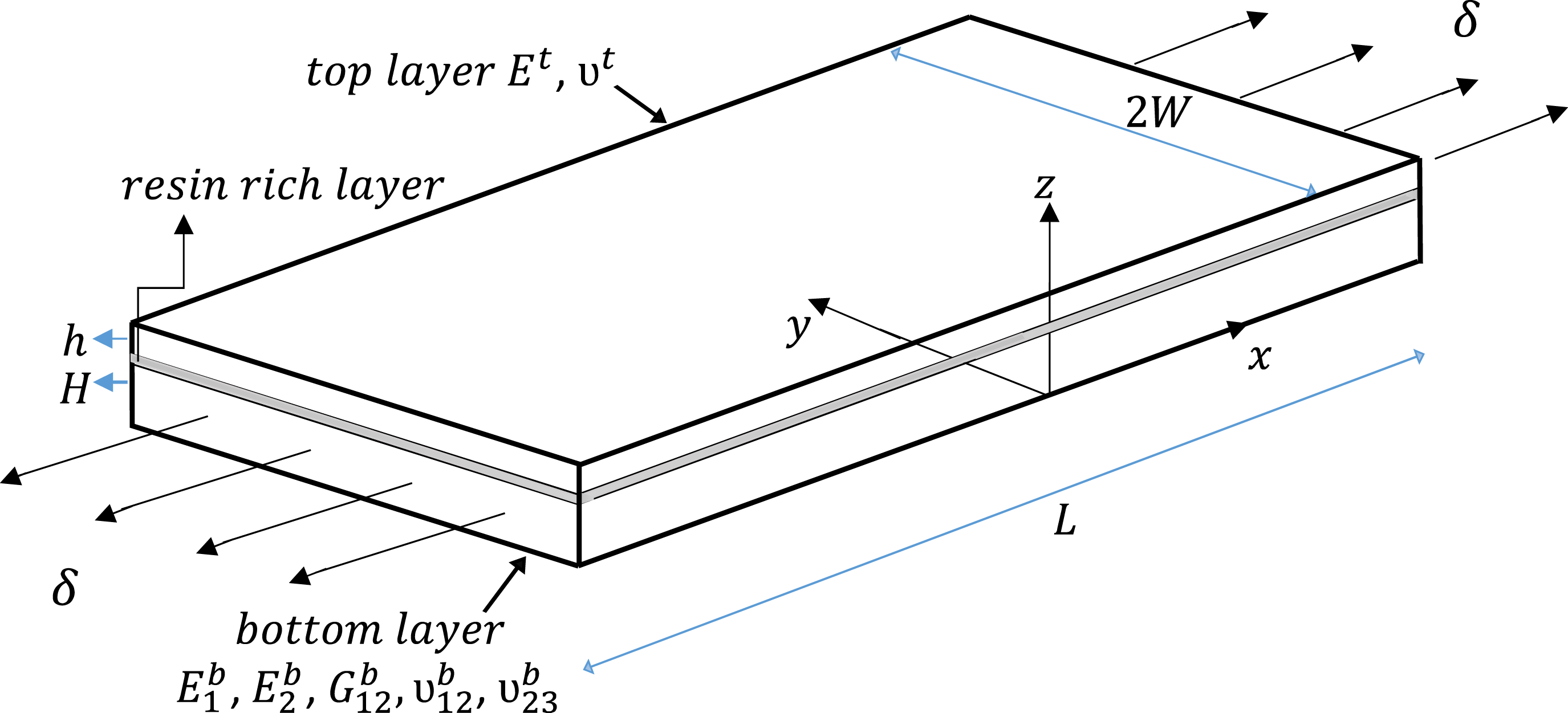
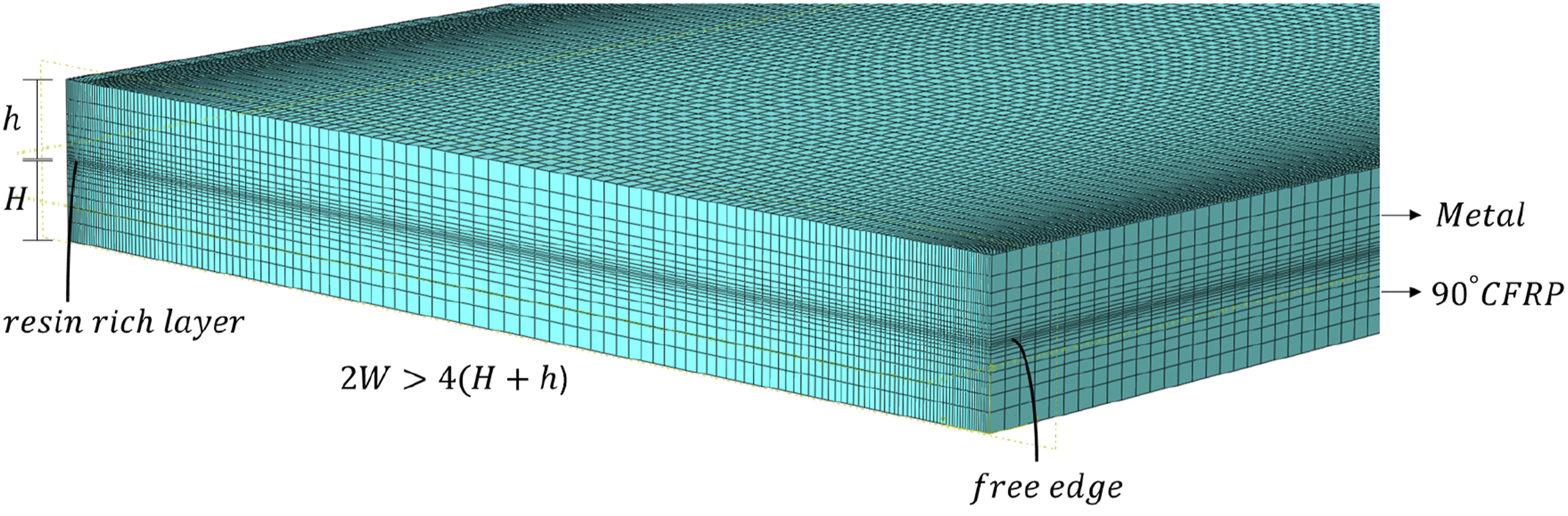
In Figure 1, a bi-material laminate is schematically presented. and are the thickness of the bottom and top layers, respectively, is the length, and is the width. Assume orthotropic material, such as carbon fibre-reinforced polymer composites, for the bottom layer, and isotropic material, such as metal, for the top layer. The laminate is subjected to uniform loading using displacement control , and the reaction force resulting from this applied displacement is used to calculate remote stresses . The bottom layer is oriented at . Global coordinate system of the laminate is represented with -axes, where are in-plane and is out-of-plane () directions, respectively, and is situated at the bottom surface of the bottom layer. In addition, both layers are assumed as linearly elastic. The resin rich layer is modelled as a transition layer at the interface between the bottom and top layers.
Three-dimensional bi-material laminate.
Dimensional analysis
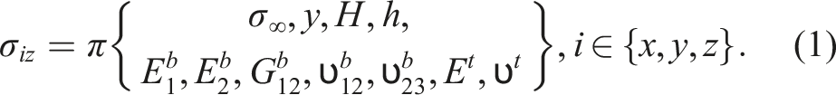
The interlaminar stresses for a general bi-material laminate as in Figure 1 depend on the set of parameters such as remote stresses ; elastic material properties of bottom layer and top layer ; geometric dimensions, and ; and distance from free edge of the laminate . Therefore, for a given orientation of bottom composite ply, the interlaminar stresses for an arbitrary bi-material system and geometry is expressed as:
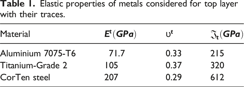
Material invariant trace,, defined in Ref.50 is utilised to represent the elastic properties of the two substrates. The trace of the bottom composite layer, denoted with , is determined from the 3D elastic stiffness matrix. The Composite Laminate Plate Theory (CLPT) is incorporated to generate the trace-normalised 3D stiffness components (see Appendixes A & B) for several CFRP materials, and the Master Ply is defined based on the average values of these components. The computation of individual elastic constants for an arbitrary CFRP material can then be calculated using their individual traces and the Master Ply trace-normalised components. Similarly, the top metal layer trace, , is computed from 2D elastic stiffness matrix. The elastic properties of metals considered are taken from material suppliers and are listed in Table 1 along with their corresponding traces.
Elastic properties of metals considered for top layer with their traces.
Material
Aluminium 7075-T6
71.7
0.33
215
Titanium-Grade 2
105
0.37
320
CorTen steel
207
0.29
612
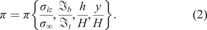
The incorporation of trace reduces the number of material properties to a single material property. This allows a convenient way to study the effects of material contrast. Therefore, following sequential elimination, equation (1) can be expressed in terms of non-dimensionalised groups as:
For a given bottom layer orientation, the interlaminar stress component for a bi-material system reads:
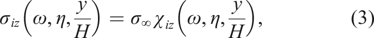
where are non-dimensional stress functions of non-dimensional parameters: (the material parameter), (the geometric parameter, denoting an inversely expressed dimensional group), and . Once the stress functions of a bi-material laminate in equation (3) are known, interlaminar stresses can be determined for an arbitrary load, material, and geometry without re-solving the underlying boundary value problem.
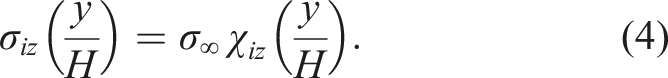
For a given interface in a hybrid symmetrical (cross and angle-ply within metal layers) laminate, the interlaminar stresses for a given , , and stacking sequence is written as:
Equation (4) can also be utilised for a monolithic symmetrical laminate with a given stacking sequence and material system, where interlaminar stresses at a dissimilar interface can be determined for an arbitrary ply thickness once is evaluated.
Theory of critical distances
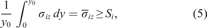
The Line Method (LM) is an averaged formulation and one of the manifestations of Theory of Critical Distance (TCD).51 It describes that the failure occurs when the value of stress averaged over a certain characteristic length, equals the corresponding strength of the material. Kim and Soni52 utilised this criterion for interlaminar normal stress distribution at the free edge in composite laminates. The LM for an interlaminar stress component is written as:
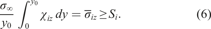
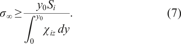
where is an average of a stress component, is the corresponding interlaminar strength, and is the critical length. Equation (5) is rewritten from equations (3) or (4) as:
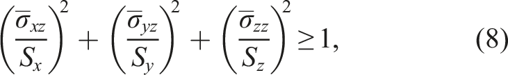
Equation (7) is the average stress criterion that involves a single component of interlaminar stress. Fracture may be induced due to multiple interlaminar stresses that exist at a particular interface. In the fracture criterion proposed by Sun and Zhou53 the quadratic interaction of the interlaminar stress components is written as:
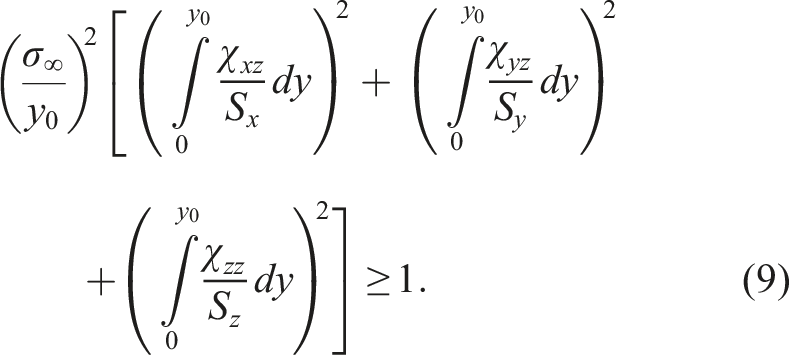
where and are interlaminar shear strengths for and , respectively, and is interlaminar normal strength (tensile) for . Combining equations (4) and (8), the mixed-mode interlaminar average stress criterion reads:
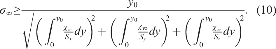
The integrals in the equation (10) are computed numerically. Equation (10) predicts the failure for a given interface due to multiple interlaminar stresses.
Finite element model
The Finite Element (FE) model is utilised to evaluate the interlaminar stresses numerically. The normalised interlaminar stresses, , can subsequently be determined using equation (4). A thin resin-rich layer is introduced at the hybrid metal/composite interface where stress assessment is required. The three-dimensional numerical model is incorporated in commercial FE software and the interlaminar stresses are computed at the integration points of elements within the resin layer. The elastic properties of this layer are assumed as, , and . The three-dimensional model in utilises 8-node linear brick, reduced integration, C3D8R elements. The resin-rich layer contains one through-the-thickness element, and a typical FE mesh is presented in Figure 2. The integration point of elements at the free edge is situated at , which is sufficiently close to the free edge . This is to ensure that the current numerical model captures the weakly singular nature of interlaminar stresses.
Typical FE mesh at the free edge of a bi-material laminate.
The analysis in Ref.54 revealed that a resin-rich layer with thickness of 2% of the ply thickness ensures accurate computation of the interlaminar stresses. Furthermore, there is no practical difference in stresses obtained when utilising quad over linear brick elements.55 Therefore, thickness of the resin-rich layer as 2% of the composite layer and linear brick elements are utilised throughout the present study.
It is noted that the resin rich layer mimics the adhesive layer at hybrid interfaces, as they have similar properties. Although the actual adhesive layer thickness used in experiments is 0.2 mm thick, the resin layer thickness representing adhesive film in hybrid laminates is taken as 2% of the composite layer throughout, as mentioned above. The adhesive film as 0.2 mm is within 10% of the composite layer considering different configurations of hybrid laminates. It is shown in Ref.54 that the influence of the variance of resin layer thickness on the distribution of interlaminar stresses is insignificant when within 10%. While a thinner adhesive film potentially increases the singularity order of stresses at the free edge, the use of an average stress criterion (TCD) for fracture prediction makes these effects insignificant in the current calculations.
Experimental
The present experimental study investigates the initial failure in hybrid and monolithic composite laminates using Edge Delamination Tests (EDT) performed under uniformly remote tensile loading.
Specimen characteristics and manufacturing
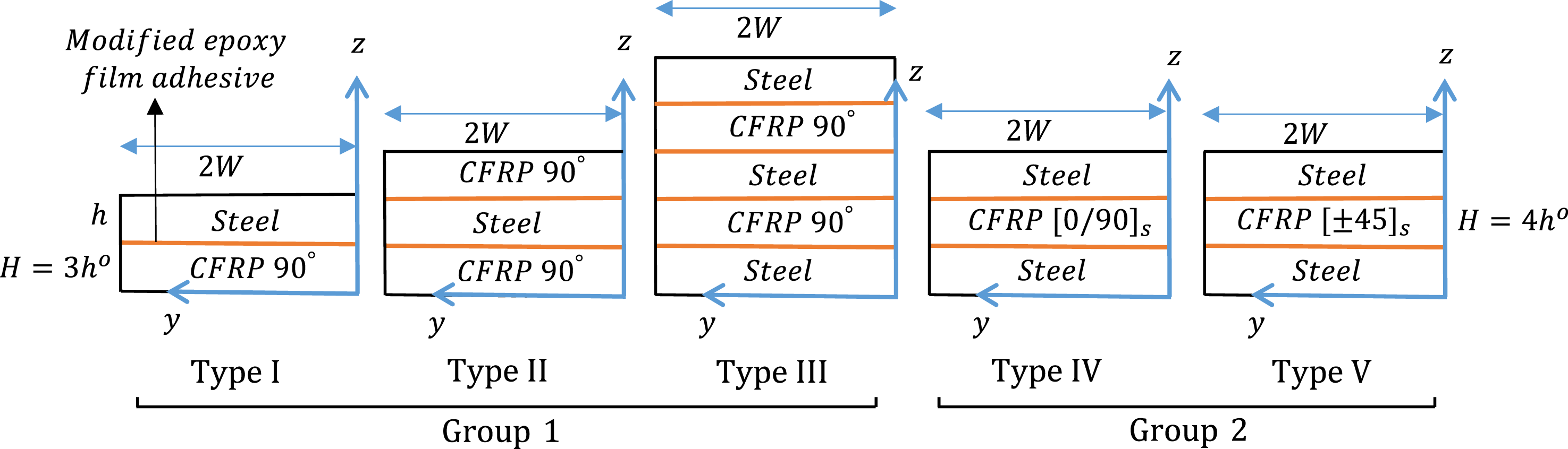
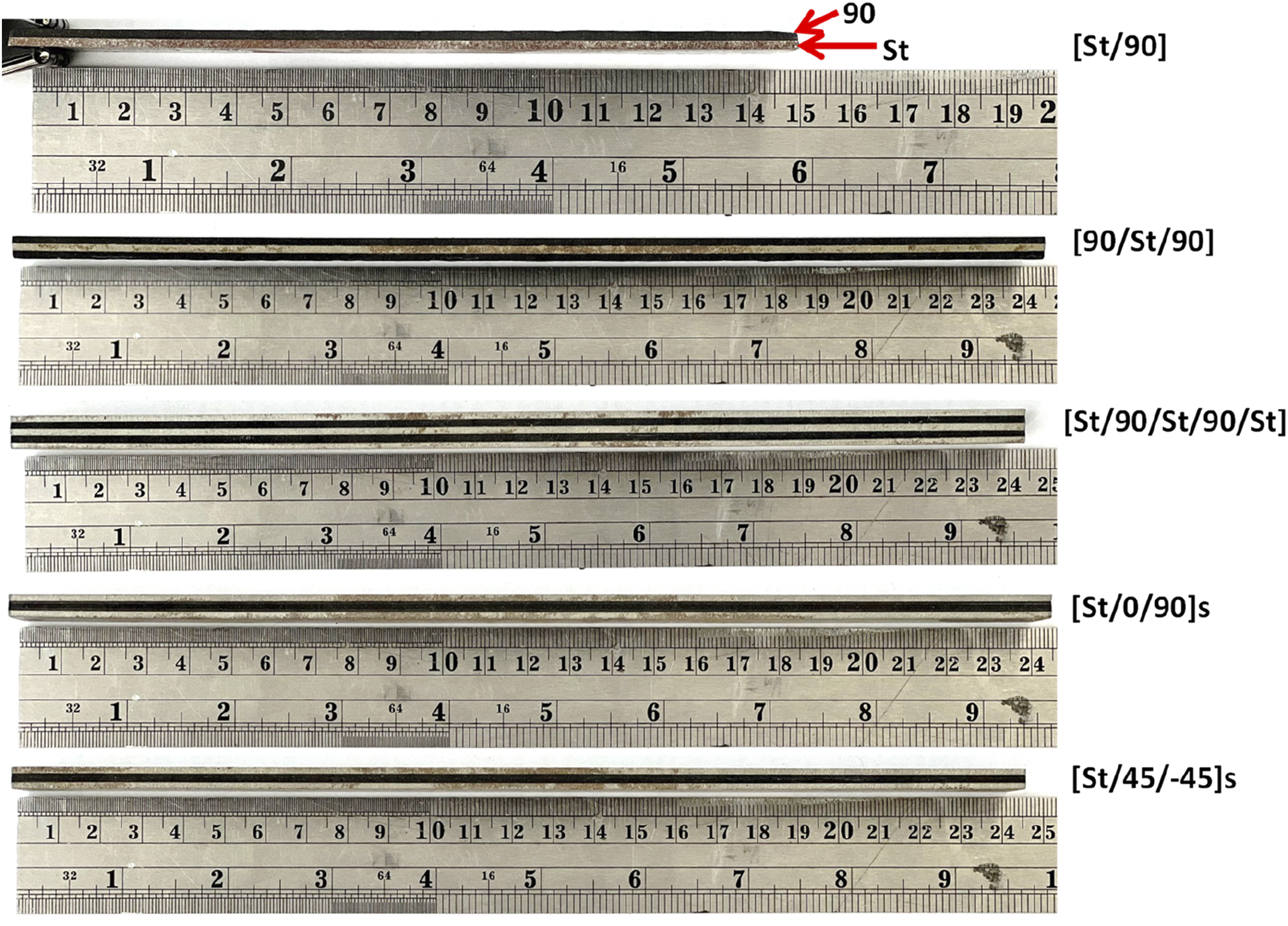
The materials considered in this study are carbon/epoxy M79/UD600 and CorTen Steel. The number of specimens is categorised into three groups. Group-1 comprise generally stacked hybrid laminates which consists of Type I, II and III configurations, as schematically shown in Figure 3. Type I represents a bi-material laminate ([St/90]) with a steel layer overlaid onto a composite layer (oriented at ). Type II consists of the interposition of a steel layer between two composite layers ([90/St/90]). Type III is an alternating arrangement of steel and composite layers, resulting in a configuration with [St/90/St/90/St]. Group-2 comprises Type IV and V configurations, which are symmetrical hybrid laminates. Type IV denotes a cross-ply laminate overlaid between two layers of steel (), while Type V represents an angle-ply laminate overlaid between two layers of steel (), as shown in Figure 3. Group-3 is composed of monolithic angle-ply laminates, , where and .
Different types of hybrid laminates considered for experimental investigation.
The surface of the steel shims was polished using emery papers ranging in grain numbers from #60 #80 to achieve a suitably rough yet chemically active surface, thereby promoting enhanced mechanical interlocking. A modified epoxy film adhesive, Hexbond 679, fully compatible with M79 and suitable for steel to composite bonding, was employed to facilitate the adhesion of hybrid steel/composite interfaces. The Hexbond 679 is utilised in all hybrid interfaces as illustrated in Figure 3. To optimise bonding efficacy, hybrid panels were clamped and pressurised using bench vice for 20 mins prior to curing, ensuring enhanced interfacial adhesion. All the laminates are cured at 70 and 1.01325 bar (vacuum bag cure) with 2 /min as heat up rate for 480 min in an autoclave following the temperature cycle (70 *480 min or 80 *360 min or 90 *240 min), pressure cycle (0.5-5 bar), and heat up rate (0.5-5 /min) recommended by the composite prepreg manufacturer. After curing, the specimens were cut using abrasive water jet cutting into desired dimensions. Hybrid panels were cut into specimens with lengths 200 mm and widths of 20 mm, except for Type I ([St/90]), which had lengths of 145 mm and widths of 30 mm. Monolithic angle-ply panels were cut into specimens with lengths 160 mm and widths of 20 mm. The difference in specimen dimensions was because of practical resource constraints such as material availability. It was reported in Ref.56 that the scaling of length and width of FML coupons have little influence on the tensile fracture strength, an effect that was attributed to free edge delamination. In another study,57 no effects of scaling dimensions on tensile strength in FML were observed. In fact, the width does not influence the interlaminar stress field, provided the specimen is wide enough (which is the case in the present study), and hence should not affect the strength.58 The gauge length constituted 60% of the total length of specimen length across all laminates. Nominal ply thickness of a composite ply measured after curing is = 0.617 mm. The thickness of a steel shim is = 1.5 mm and the epoxy film adhesive is 0.2 mm thick.
Material mechanical characteristics
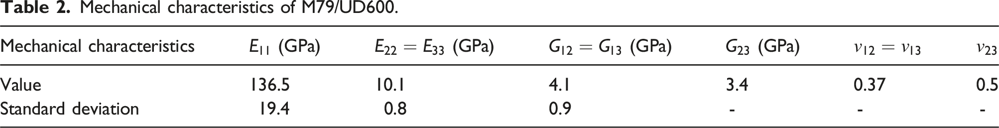
The mechanical properties of the M79/UD600 material system were characterised experimentally using , , and laminates. Tensile tests performed on these laminates allows to assess the in-plane mechanical properties summarised in Table 2 where represents the longitudinal modulus of elasticity, the transverse modulus of elasticity, the in-plane shear modulus and the longitudinal Poisson’s ratio. Employing the transverse isotropic assumption, the out-of-plane elastic constants were derived from experimentally measured characteristics, with assumed to be 0.5.59 Elastic constants for CorTen steel were obtained from the material supplier and are listed in Table 1. Strain measurements were obtained using extensometer, strain gauges, or a combination of both.
Mechanical characteristics of M79/UD600.
Mechanical characteristics
(GPa)
(GPa)
(GPa)
(GPa)
Value
136.5
10.1
4.1
3.4
0.37
0.5
Standard deviation
19.4
0.8
0.9
-
-
-
Notably, the influence of thermal and moisture expansion in both hybrid and monolithic angle-ply laminates, induced by curing, on interlaminar stresses was not taken into the consideration. In the development of the hybrid laminate, the combination of CorTen steel and carbon/epoxy M79 UD600 was specifically selected to minimise residual thermal stresses during curing. This is because M79 is a low-curing temperature (70°C) epoxy, which, when combined with HexBond 679 adhesive, is compatible with steel/composite bonding at this low curing temperature.
The absence of delamination and bending post-curing, as well as no delamination after abrasive water jet cutting of the pristine hybrid specimens, indicated that residual thermal stresses are negligible. Given that the hybrid Type I ([St/90]) laminate is an asymmetric bi-material system, it is highly susceptible to bending if significant residual thermal stresses were present. Typically, the experimentally measured curvature of a hybrid laminate during the cooling process to the room temperature can be used to estimate residual thermal stresses,60,61 assuming the curing temperature is a stress-free baseline. In this study, no measurable curvature was observed in the post-cured pristine specimens, suggesting that the thermal residual stresses are insignificant. A picture of post cured pristine hybrid specimens demonstrating flatness, and no curvature is shown in Figure 4. Furthermore, it is noted that thermal expansion effects in bi-material steel/epoxy systems are often counterbalanced by moisture effects in a laboratory environment,60 further supporting the minimal impact of residual stresses in hybrid laminates. This counterbalance effect is also observed on monolithic composites.62
Flatness of hybrid laminates post curing.
Testing procedure
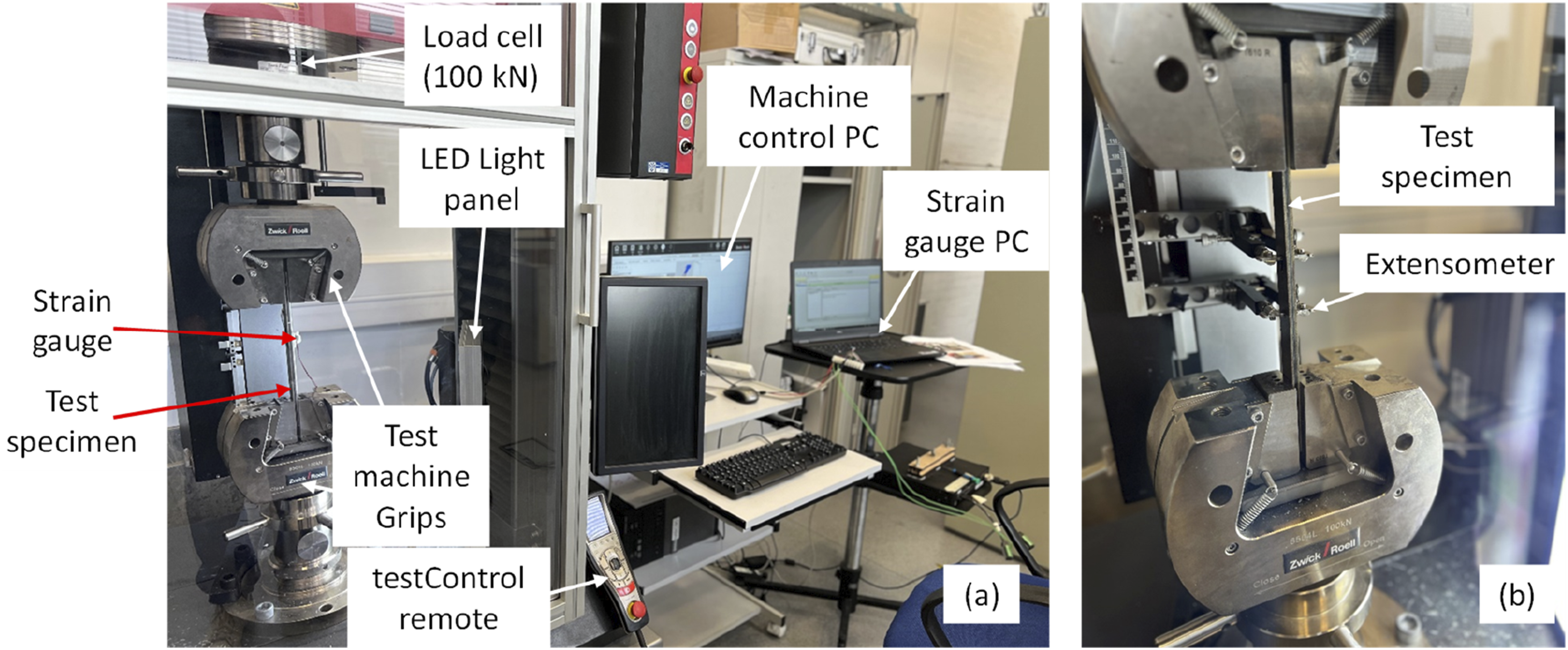
The EDT were performed on Zwick Roell Z100 tensile testing machine with a 100 kN load cell in a displacement control at a crosshead speed of 2 mm/min. In the present experiments, tests were run until the initial indication of fracture, involving a combination of visual and audible detection, along with measured stiffness loss indicated by an instantaneous drop/deviation in the load-deflection curve. This approach, as utilised by O’Brien63 for detecting delamination initiation, was complemented by a high-speed digital camera with capability to capture 240 fps to monitor the fracture at the free edges. Specimen edges were polished to enable inspection by a stereo microscope to confirm the fracture. A picture of the tensile test setup with specimen attached to strain gauge and an extensometer is shown in Figure 5.
Tensile test setup with the specimen attached to (a) a strain gauge and (b) an extensometer.
Results
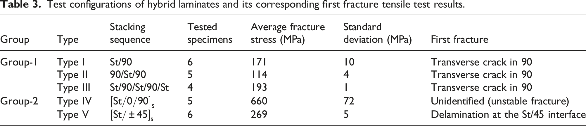
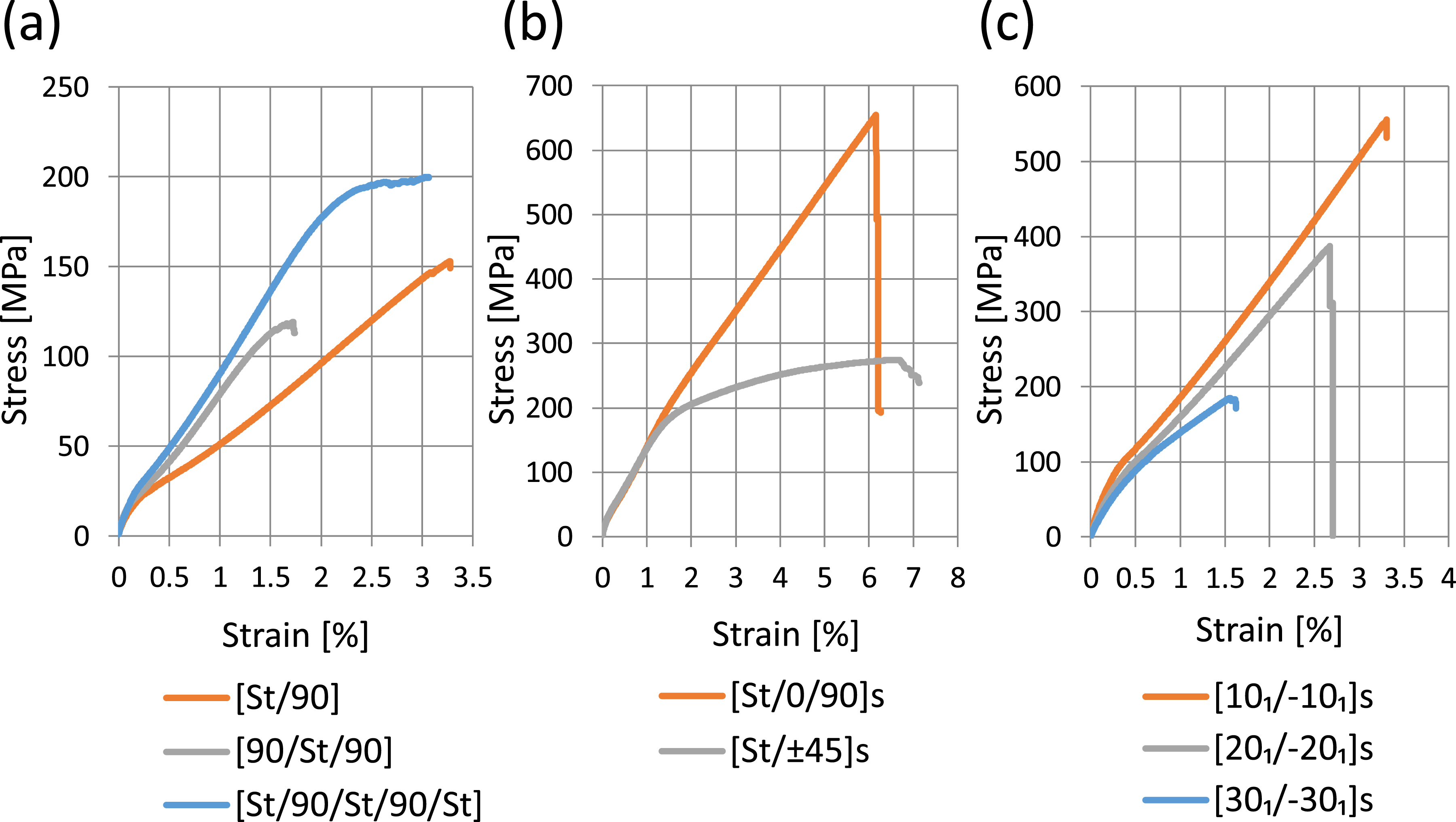
The prominent failure mechanisms experimentally identified in all the laminates were transverse matrix cracking, interlaminar fracture in composites and interlaminar debonding between steel-composite interfaces. Tables 3 and 4 synthesises all the test results for hybrid and monolithic laminates, respectively, and the corresponding stress-strain curves are shown in Figure 6.
Test configurations of hybrid laminates and its corresponding first fracture tensile test results.
Group
Type
Stacking sequence
Tested specimens
Average fracture stress (MPa)
Standard deviation (MPa)
First fracture
Group-1
Type I
St/90
6
171
10
Transverse crack in 90
Type II
90/St/90
5
114
4
Transverse crack in 90
Type III
St/90/St/90/St
4
193
1
Transverse crack in 90
Group-2
Type IV
5
660
72
Unidentified (unstable fracture)
Type V
6
269
5
Delamination at the St/45 interface
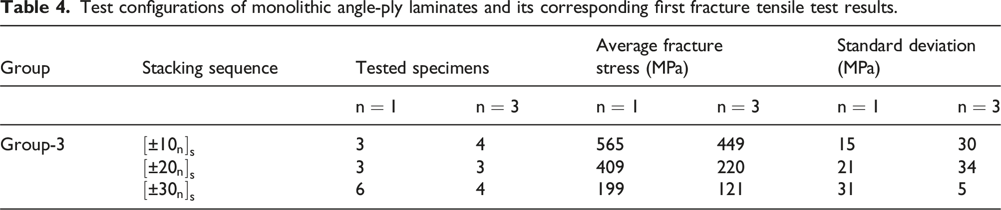
Test configurations of monolithic angle-ply laminates and its corresponding first fracture tensile test results.
Group
Stacking sequence
Tested specimens
Average fracture stress (MPa)
Standard deviation (MPa)
Group-3
3
4
565
449
15
30
3
3
409
220
21
34
6
4
199
121
31
5
Typical stress-strain curves for the considered laminates.
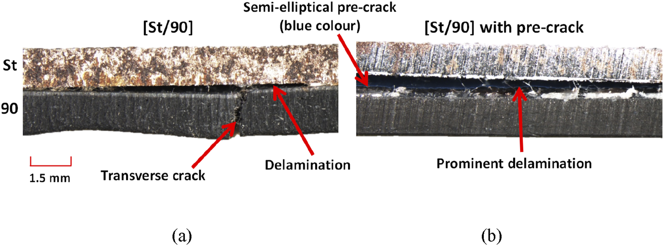
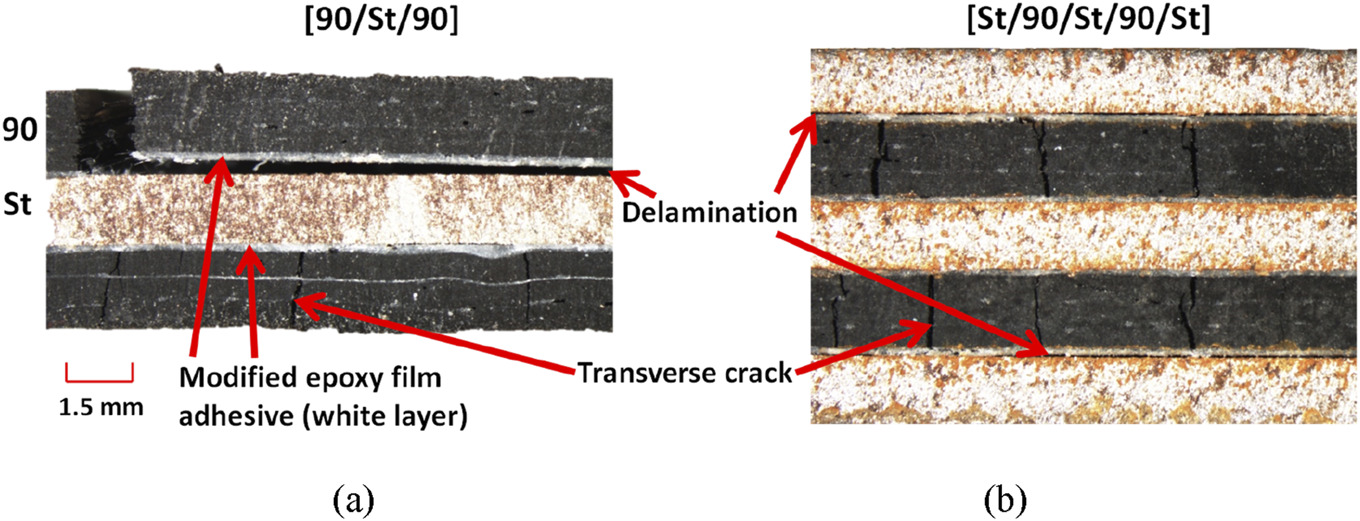
All three hybrid laminate configurations in Group-1 initially exhibited linear stress-strain behaviour until the fragmentation (transverse cracking) was spotted in the composite layers. This transverse cracking is followed by interlaminar delamination at the steel/composite interfaces, predominantly in the immediate vicinity of fragmentation. The fracture growth was stable and therefore some of the tests were stopped before failure indication on the load-displacement plot to further analyse the samples using microscopy. Microscopic images shown in Figure 7(a) for Type I and Figure 8 for Type II and III show fracture mechanisms. The initial linear response is where load transfer occurs between steel and composite. A slight drop in stress-strain response (see Figure 6(a)), or equivalently a stress plateau region in Type III, indicates initiation of cracks at multiple sites. Further loading leads to stable delamination of the hybrid laminates. Additionally, Type I, II and III configurations exhibit similar behaviour except that the Type III shows higher load carrying capacity than the rest.
Typical failure mechanism of Type I [St/90] laminate (a) without pre-crack, and (b) with semi-elliptical pre-crack at the hybrid interface.
Typical failure mechanism of (a) Type II [90/St/90] and (b) Type III [St/90/St/90/St] hybrid laminates.
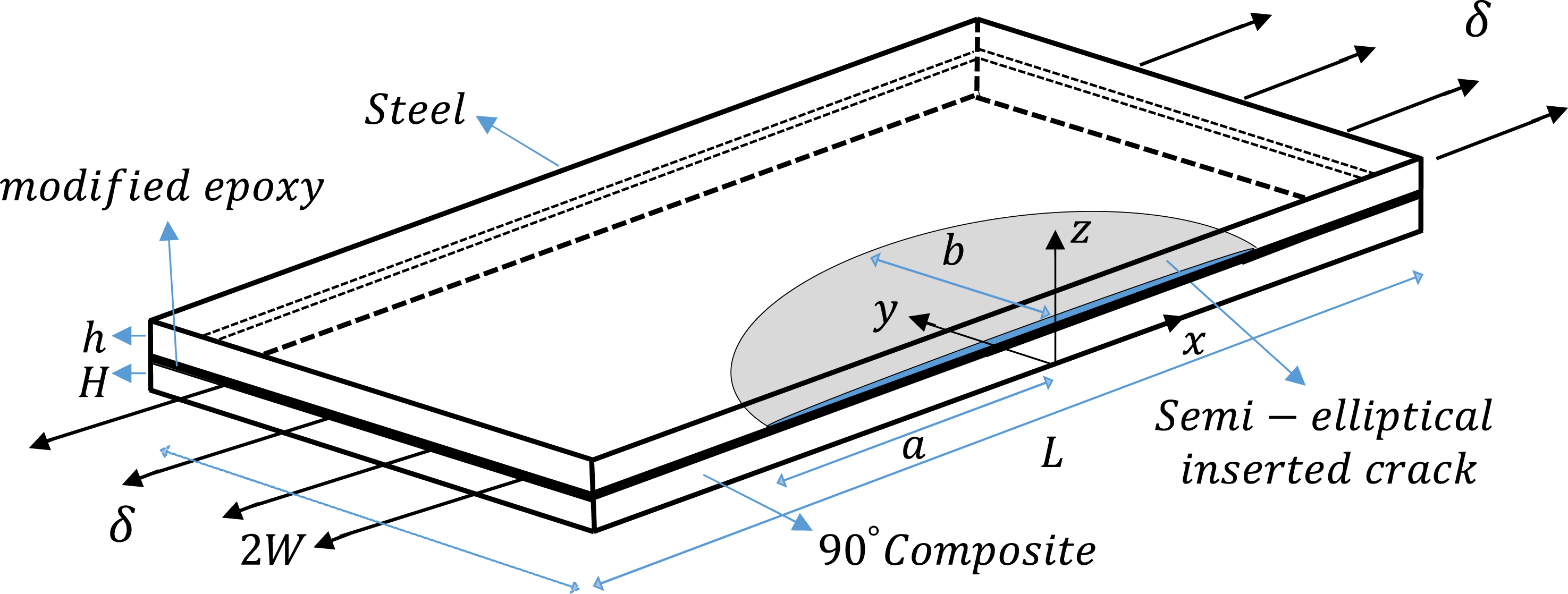
A separate Type I laminate was also prepared with a semi-elliptically shaped pre-crack introduced using release film inserted at the free edge. The crack was inserted at the steel-adhesive interface. This was to investigate whether the crack would trigger a noticeable delamination prior to transverse cracking. The blue coloured pre-inserted crack, with semi-axes and as 15 mm and 5 mm, respectively, can be seen in micrograph shown in Figure 7(b) post fracture and the schematic diagram of this specimen is illustrated in Figure 9. A prominent delamination was observed, as shown in Figure 7(b), with the first fracture occurring at approximately 10% lower fracture stress compared to the Type I laminate without pre-inserted crack. However, transverse cracks were still observed elsewhere, distinct from this prominent delamination region.
A schematic diagram of semi-elliptical pre-crack at the hybrid interface.
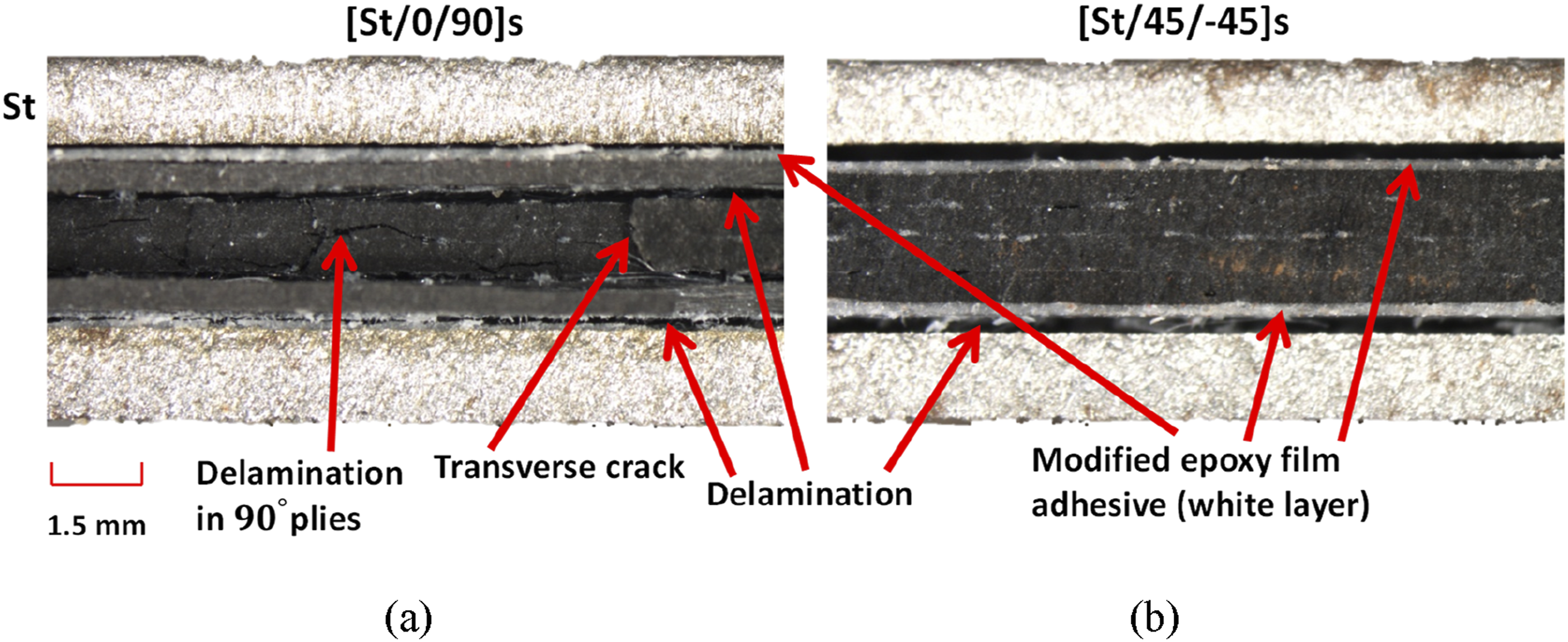
The hybrid symmetrical Type IV () laminate from Group-2 exhibited bilinear trend in stress-strain response (Figure 6(b)), followed by a sudden unstable (brittle) and audible failure. Composite failure occurred instantaneously after first fracture. Prominent interlaminar delamination were observed both at the hybrid steel-composite and within composite at 0/90 interfaces, along with transverse cracks in the 90 plies. In some cases, delamination also progressed in plies, while in other specimens, intraply failure of the was observed. Micrograph Figure 10(a) illustrates different failure modes observed. The experimental results in the Type IV laminate also showed some plastic deformation in the steel. Due to the challenge of explaining the fracture source with certainty in the Type IV laminate test, a numerical investigation on the interlaminar stresses, that sheds some light on the fracture origin, will be conducted later.
Typical failure mechanism of (a) Type IV and (b) Type V hybrid symmetrical laminates.
Type V () hybrid symmetrical laminate exhibited non-linear stress-strain response (Figure 6(b)). The fracture and crack propagation were observed stable, and the first fracture stress was about 41% of that of Type IV. The interlaminar delamination at the hybrid steel/composite interface was the first and primary mode of fracture and is illustrated in Figure 10(b). In addition to that, local plastic deformation was observed induced by interfacial delamination, which placed imperfection in the laminate.
Furthermore, an interesting observation was that interlaminar delamination occurred consistently between steel/adhesive layer in all the hybrid laminates. This may be primarily because the epoxy matrix of composite and adhesive film has similar properties.
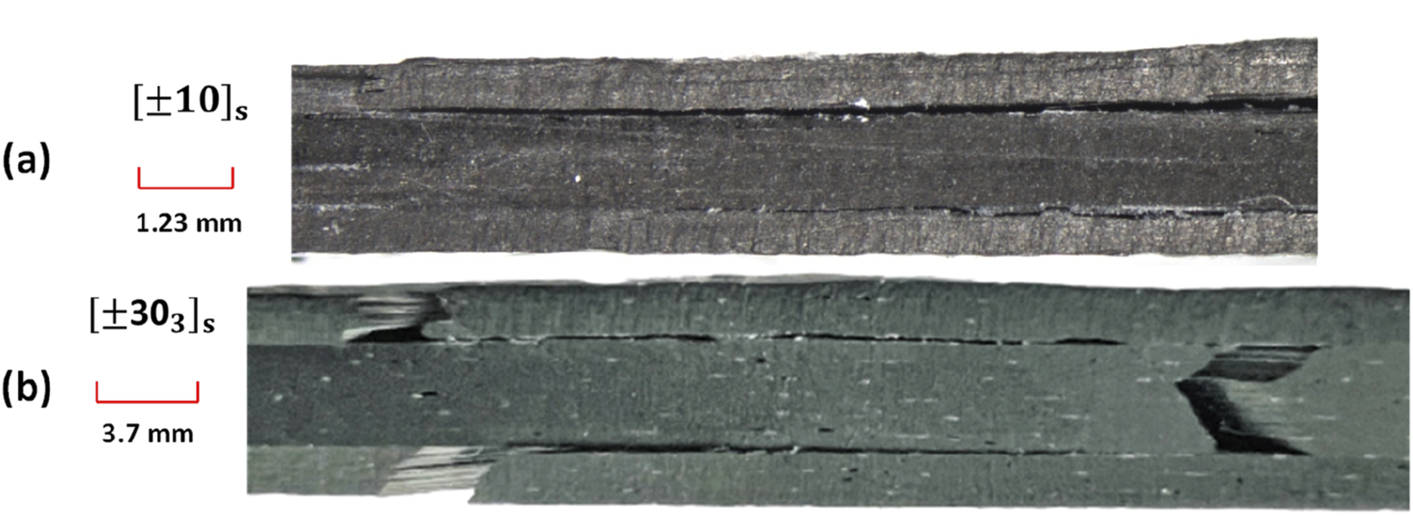
In Group-3 monolithic angle-ply laminates, , where and , delamination were observed at the / interfaces, as shown in Figure 11. and laminates exhibited linear stress-strain response (see Figure 6(c)) until initiation of interlaminar delamination. The delamination growth was unstable (brittle), and failure occurred instantaneously after initiation. On the contrary the behaviour of laminates were observed exhibiting non-linear response and less unstable delamination growth was observed. Furthermore, experimental test results, listed in Table 4, indicate decrease in average fracture stresses with increasing normalised ply thickness, n. This observed size-effect phenomenon is well known and can be explained through energy considerations. A larger ply thickness implies more strain energy is stored per ply. This excess energy is in turn available for formation of fracture.64 The experiments also indicate with increasing ply orientation, , average fracture stresses decrease. These observations are in accordance with the previous experimental studies on angle-ply laminates.59,65
Delamination at the (a) +10/−10 interface of and (b) +30/−30 interface of monolithic angle-ply laminates.
Semi-analytical investigation of interlaminar stresses
This section provides a detailed analysis of the interlaminar stress distributions of the laminates (hybrid and monolithic) considered in the experimental campaign. The assessment offer insights into what specific interlaminar stress that exist at an interface may contribute to first fracture, describing whether they play a significant role in fracture mechanisms. Furthermore, the assessment will lead to information regarding the susceptibility of an interlaminar fracture across different interfaces, distinguishing between those prone to fracture and those where such occurrences are unlikely. It is noted that within the scope of current study, it is assumed that the plastic deformation of metals does not influence the interlaminar stress distributions.
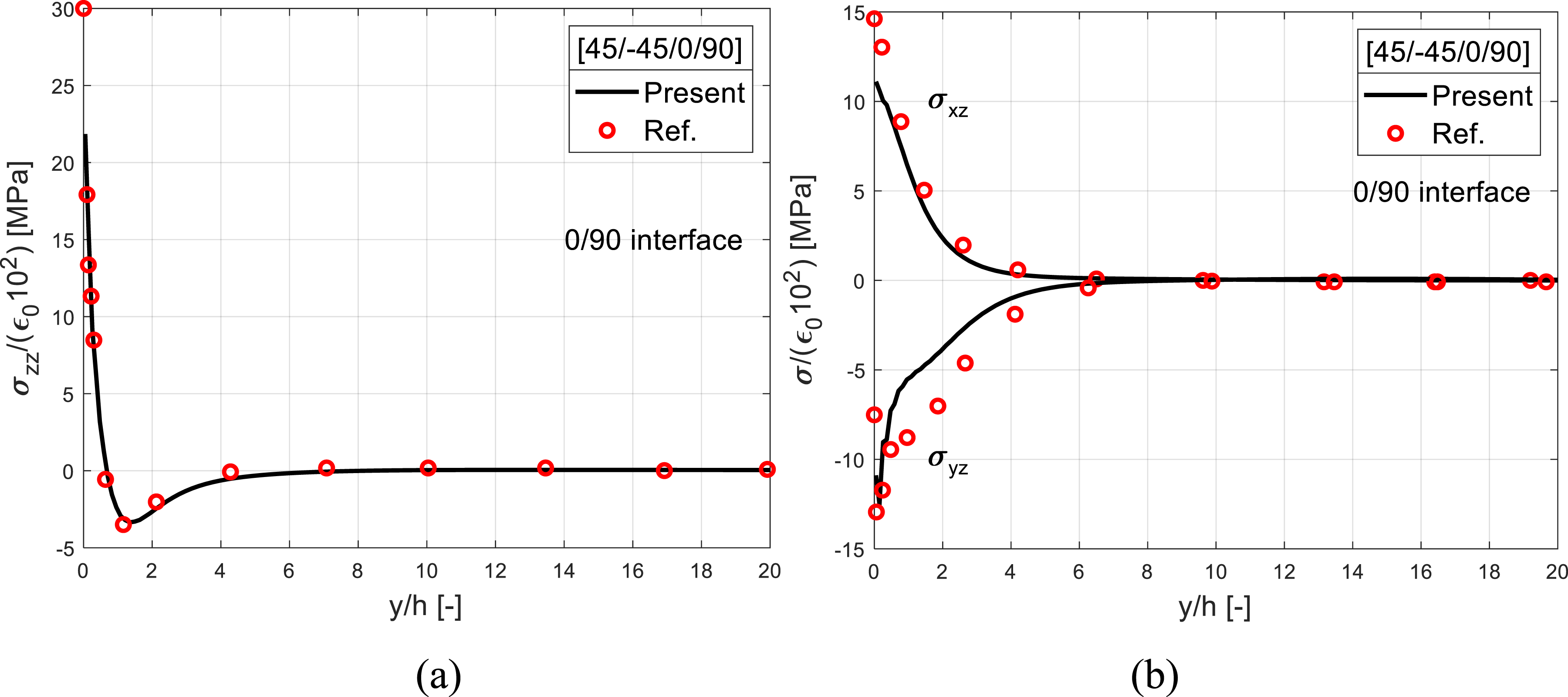
A simple semi-analytical framework to calculate interlaminar stresses, outlined in the sections on dimensional analysis and finite element model, is implemented for various hybrid and monolithic laminates. The resin-rich layer is modelled at the interface where interlaminar stresses assessment is required in both monolithic and hybrid laminates. For validation purposes, a generally stacked four-layer [45/−45/0/90] laminate with ply thickness, , is considered. Figure 12 shows the interlaminar stress distributions (as normalised by remote strain ) at 0/90 interface and is compared against the reference results taken from Ref.66. The geometric and elastic properties of a ply is also taken from Ref.66. In general results show close agreement to that of reference results. The interlaminar normal stress, , at the free edge yields stress singularity and is illustrated in Figure 12(a). At the free edge, shear stress yields a finite value, while value also yields a finite value but tends towards zero, as presented in Figure 12(b).
Interlaminar (a) normal and (b) shear (, ) stress distributions at the 0/90 interface of generally stacked [45/−45/0/90] laminate in comparison to Ref.66.
Hybrid Type I ([St/90]) bi-material laminate
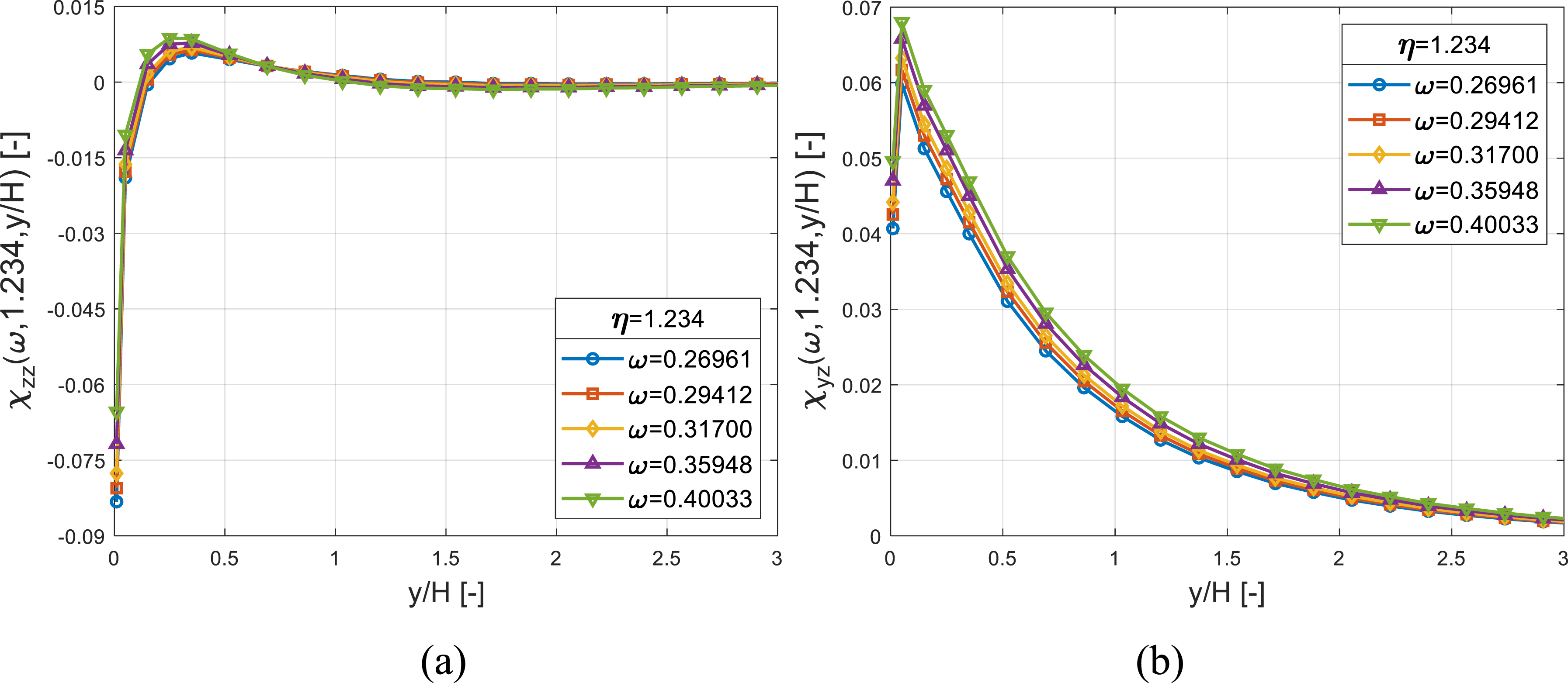
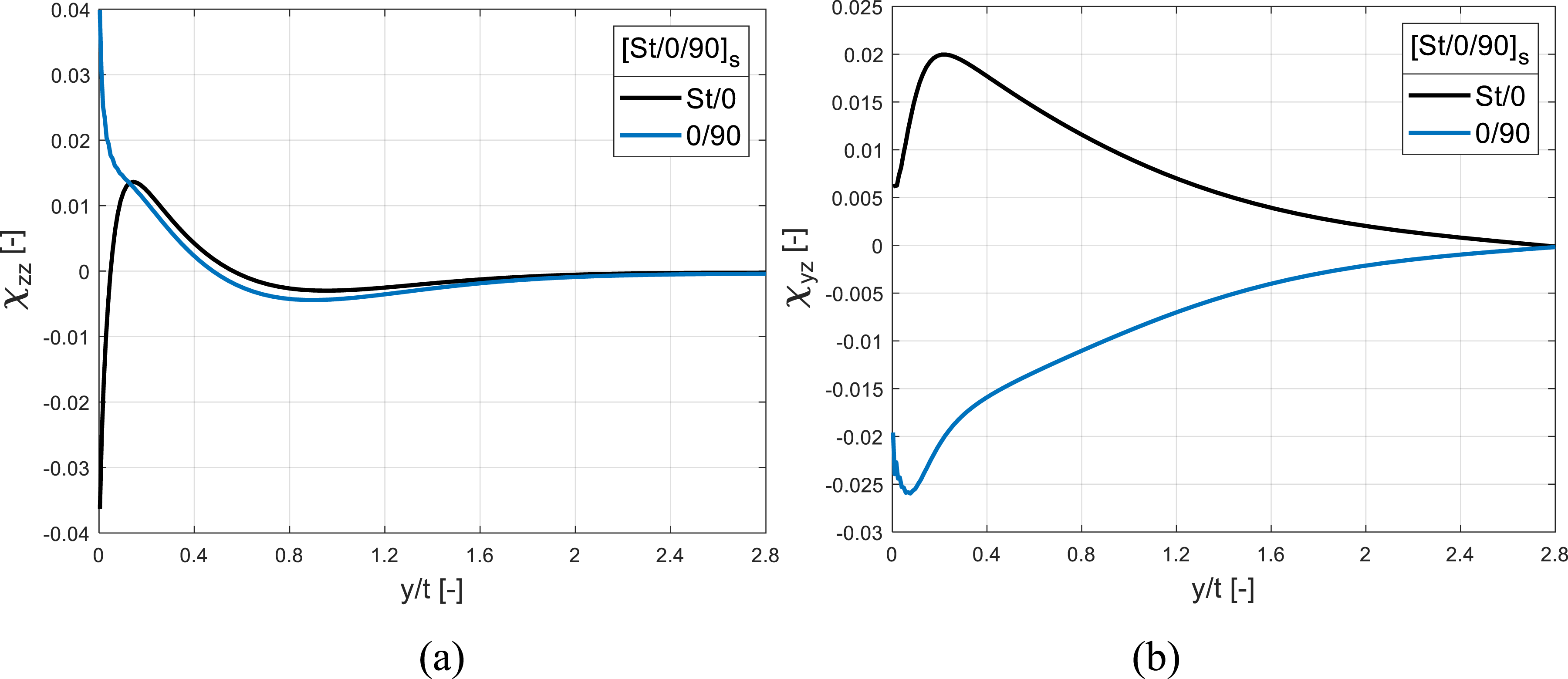
Type I bi-material laminate (see Figure 1) is studied for various material, , and geometric, , parameters. Investigation of these parameters, influencing the interlaminar stresses is imperative for fracture criterion. Figure 13(a) and (b) shows the effects of on normal, , and shear, , stress functions for a fixed . The influence of on the distribution is found to be insignificant, and compressive at the free edge. In the case of , the variation in the distribution increases moderately with increasing . It should be noted here that the value of geometric parameter corresponds to the Type I laminate considered in the experiments, as shown in Figures 3, and 13 illustrates the corresponding influence of material contrast (either in metal or composite) on interlaminar stresses.
Normalised interlaminar (a) normal and (b) shear, stress distributions at the metal/composite interface for various material parameter, , values.
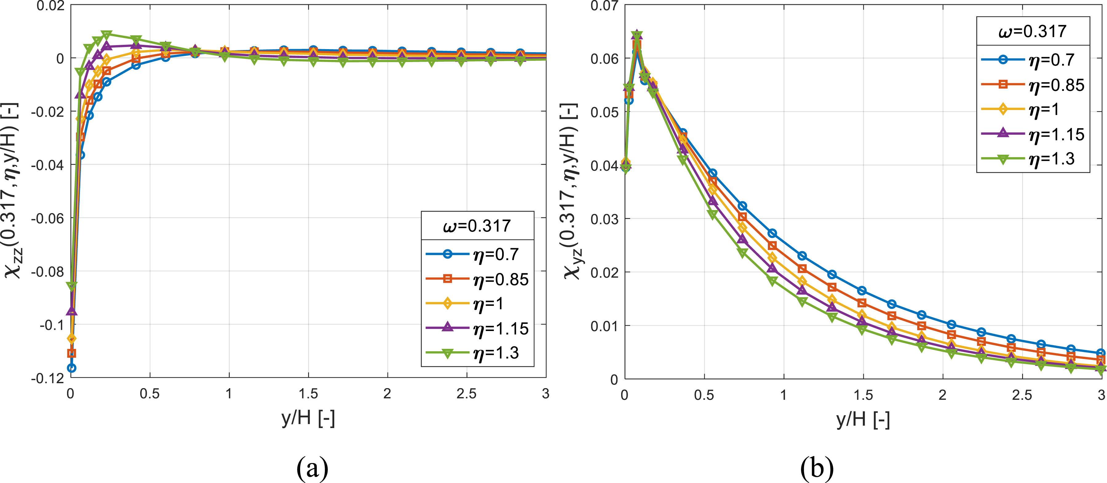
Subsequently, the influence of on a bi-material laminate on non-dimensionalised functions is investigated for a given . and distributions are presented in Figure 14(a) and (b), respectively. The distribution is again compressive in nature that increase near the free edge and decrease away from it as is increased, with a crossover point occurring around . On the contrary, distribution decreases throughout with increasing , except at the free edge where it remains unchanged. The material parameter corresponds to Type I laminate considered in the experimental campaign and Figure 14 shows corresponding influence of variation in layer thickness (either in steel or composite) on interlaminar stresses.
Normalised interlaminar (a) normal and (b) shear, stress distributions at the metal/composite interface for various geometric parameter, , values.
Interestingly, the component tends to approach zero at the free edge, although finite in value, indicating no contribution to fracture. However, a compressive singularity exists in the distribution of at the free edge. This singularity, as noted by Kim and Soni,67 may contribute to delay in delamination. Therefore, it is improbable for Type I ([St/90]) laminate to fracture induced by interlaminar stresses alone. This aligns with the experimental findings of Type I laminate mentioned in results section, where transverse cracks were observed first in the composite layer. The subsequent delamination in all Group-1 (Type I, II, III) laminates near transverse crack zones may be due to the compound effect of transverse cracks and interlaminar stresses interaction.
Hybrid Type IV () symmetric laminate
The interlaminar stress functions of Type IV (see Figure 3) hybrid symmetrical laminate at both steel/composite and 0/90 interfaces are illustrated in Figure 15 versus distance from free edge, , normalised with total thickness of laminate, . Normal distribution (Figure 15(a)) shows tensile singularity at 0/90 interface, while steel/composite interface exhibits compressive interlaminar stress distribution. Shear distribution tend to approach to zero (although finite) at , as presented in Figure 15(b) at both interfaces, therefore does not contribute to fracture at free edge.
Normalised interlaminar (a) normal and (b) shear stress distributions at different interfaces for Type IV () symmetric laminate.
The distribution of at the 0/90 interface within a composite is the only probable interface where fracture, mode I in nature, may be induced due to interlaminar stresses. However, there is still a possibility of ply experiencing matrix/transverse cracking before possible interlaminar fracture at the 0/90 interface. In fact, Wang et al.68 described that in cross-ply , where n = 1,2,4, laminates edge delamination alone cannot occur; rather ply transverse cracking is the first failure event. Further, Wang et al.68 explained that the load initially experienced by plies is transferred to plies, leading to stress concentration zone near the vicinity of the transverse crack in which both in-plane and out-of-plane stresses exist. Consequently, the in-plane stresses may induce intraply failure of the ply, while interlaminar stresses can cause delamination, due to the combined effect of a transverse crack and interlaminar stresses. Additionally, interlaminar shear stresses can be of significant magnitude in the presence of a transverse crack, making eventually nature of fracture propagation mixed-mode post fragmentation. Experiments conducted on Type IV laminates (results section) reveal a fracture pattern comparable to that of described. Moreover, Reiner et al.69 performed experimental study of hybrid titanium () laminates under tensile loading and confirmed matrix cracking in plies of the composites as early failure modes observed at lower load levels at 65% of ultimate tensile strength. Therefore, it is concluded that matrix/transverse cracking of plies may serve as the first fracture mechanism.
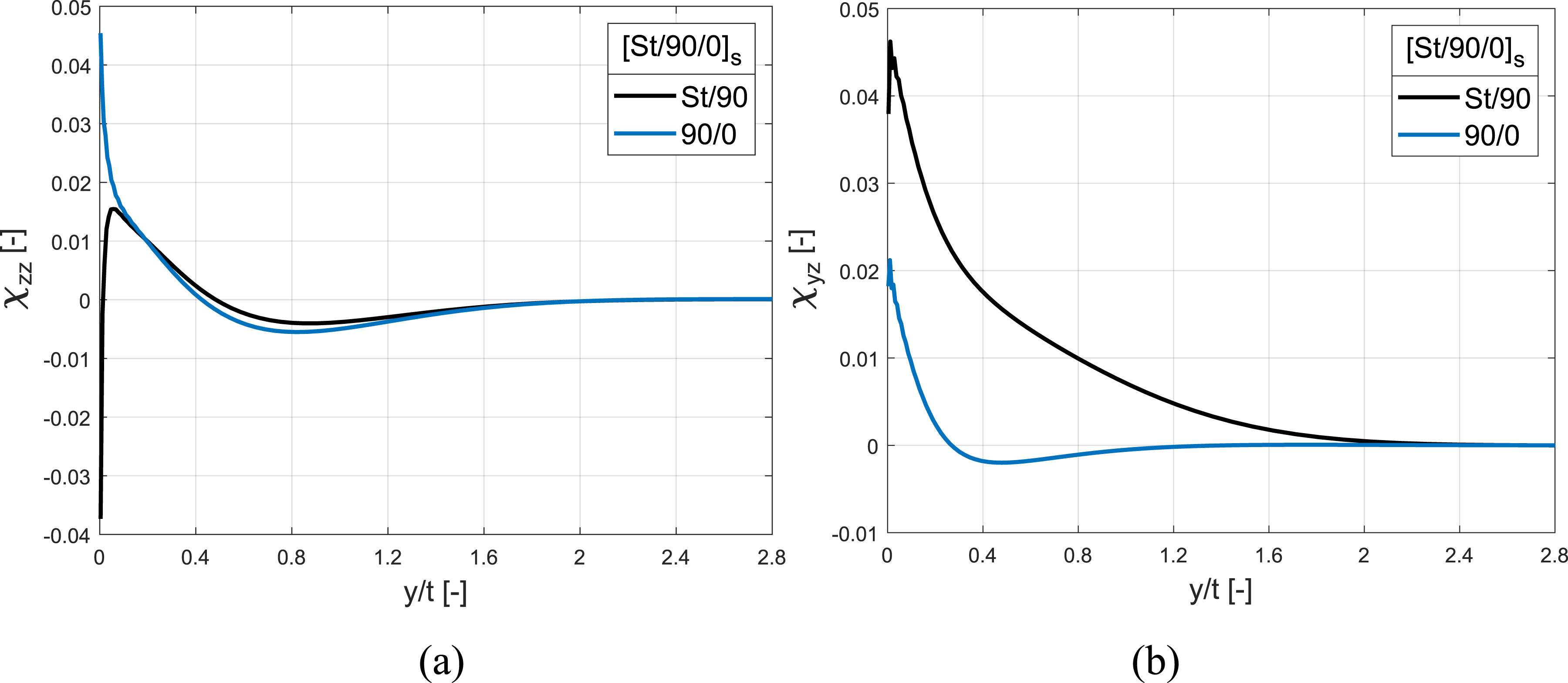
The interlaminar stress analysis of () laminate configuration is also conducted to anticipate the outcomes of experiments. Figure 16(a) and (b) depicts the normal and shear distributions at different interfaces. It is interesting to observe that no significant variation is observed compared to Type IV, suggesting a likelihood of similar fracture behaviour.
Normalised interlaminar (a) normal and (b) shear stress distributions at different interfaces for symmetric laminate.
Hybrid Type V () symmetrical laminate
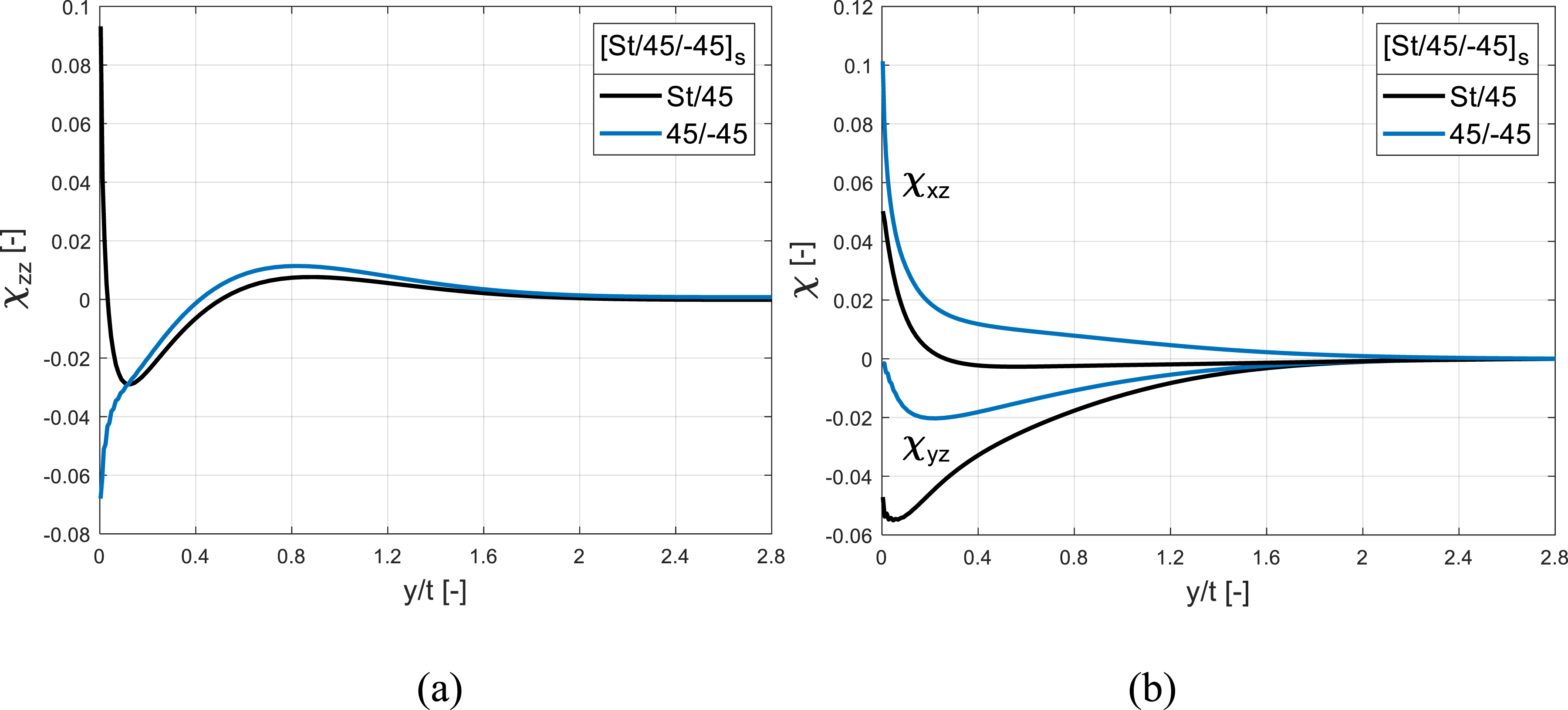
The distribution of normal, , and shear () stress functions of Type V (see Figure 3) laminate is illustrated in Figure 17(a) and (b), respectively. All three interlaminar stresses exist at both hybrid steel/composite and 45/−45 (within composite) interfaces. Steel/composite interface is particularly interesting due to existence of normal, , and shear, , singularities at the free edge. While, shear, , singularity also exist at the 45/−45 interface, the normal, , distribution is compressive at the free edge. Therefore, steel/composite interface exhibits mixed-mode I/III, while 45/−45 exhibits pure mode III fracture mechanisms at the free edge. Although, , distribution at the steel/composite interface changes its sign and the effectiveness of this component is confined in a small distance from the free edge, the interlaminar normal strength is generally lower than the interlaminar shear strength. Consequently, contribution of must be considered.
Normalised interlaminar (a) normal and (b) shear () stress distributions at the different interfaces for Type V () symmetric laminate.
The metal/polymer interface is considered weak as compared to fibre/polymer interface.70 Also, due to the variation in structural and thermal properties, the metal/composite interface is the most critical one.71 Therefore, interlaminar strengths of steel/composite interface in the present study is assumed to be low compared to interlaminar strengths of composite. Thereby, for a given interlaminar strengths, interface fracture induced at the steel/composite interface can be the first fracture mechanism. This is in accordance with the experimental findings of Type V laminate discussed in results section.
Monolithic angle-ply () laminate
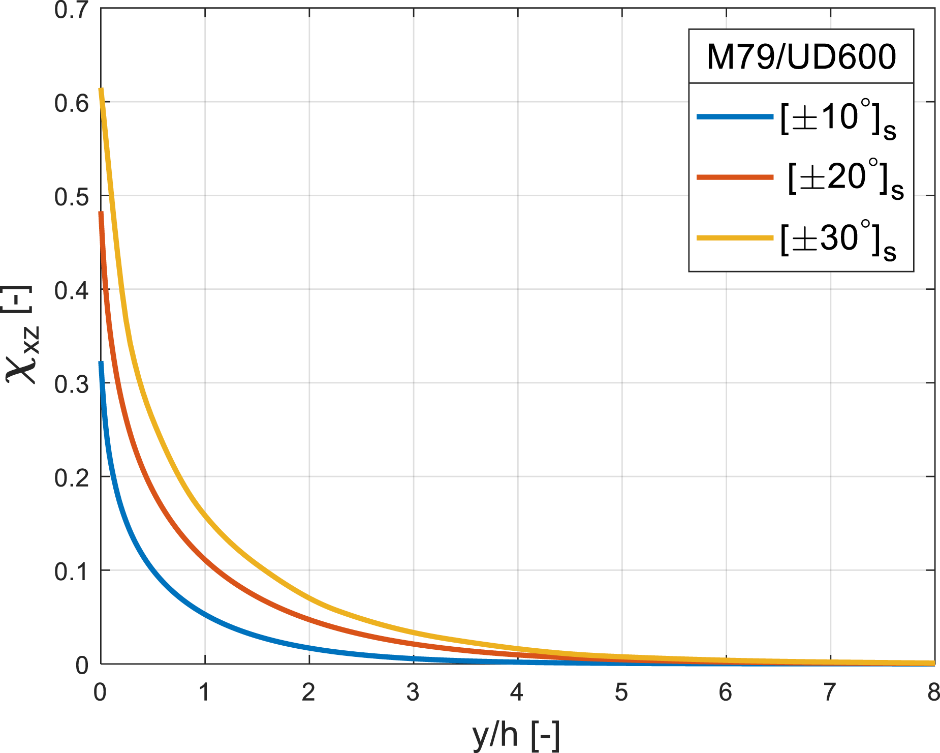
In contrast to the previously analysed hybrid laminates, the interlaminar stress distribution in monolithic angle-ply , with ply thickness, , is simpler. These laminates exhibit only an interlaminar shear component at the interface, as depicted in Figure 18, where a stress singularity in this component is evident at the free edge. This significant singularity arises due to the material mismatch at the dissimilar interface, and its magnitude increases with increase in ply orientation. Consequently, laminates display mode III delamination at these dissimilar interfaces, an observation supported by experiments outlined in results section.
Normalised interlaminar shear stress distribution at / interface for Group-3 () angle-ply laminates.
Fracture criterion
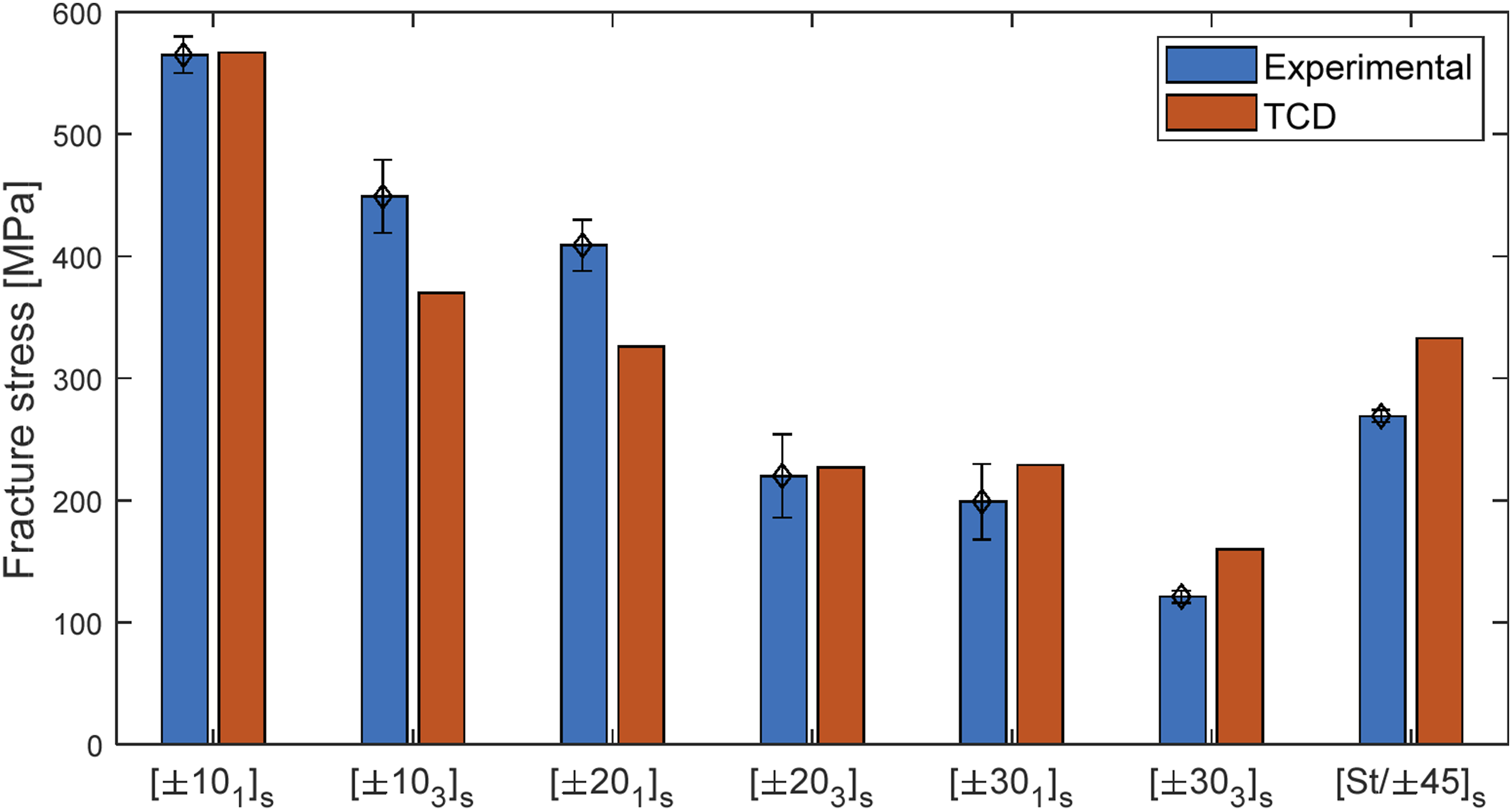
Since the experimental findings (results section) together with the numerical interlaminar stress analysis confirm that the Type V () symmetric and () angle-ply laminates exhibit interlaminar delamination as primary fracture mechanism. This section utilises TCD (average stress criterion) to predict the first fracture.
Angle-ply laminates are considered first due to their pure mode III delamination. Utilising equation (7) the fracture stress is predicted by taking the characteristic length, , equal to nominal ply thickness of the composite, as Kim and Soni52 related. Sun and Zhou53 have used characteristic length as twice of the ply thickness, while Brewer and Lagace72 and Lagunegrand et al.65 recommend its determination from experimental test results. More details on free edge delamination of monolithic composites using TCD can be found in Ref.73. The interlaminar shear strength, MPa, is taken from the material manufacturer. Figure 19 illustrates the comparison of predicted fracture stress against experimental test results. In general, a close agreement is achieved. Since a constant interlaminar shear strength value is considered for various ply thicknesses and orientation, a slight discrepancy may arise. This is due to reason that interlaminar strength depend on layer thickness.58,74 In accordance to experiments, the predicted fracture stress decreases with increasing normalised ply thickness, n. This well-known thickness effect is captured qualitatively. Furthermore, the predicted fracture stresses decrease with increase in ply orientation, , aligning with experimental observations.
Predicted fracture stresses for different laminates in comparison to the experimental test results.
After validating that TCD predict fracture strength effectively in (), an attempt was also made to obtain prediction of fracture strength in Type V () laminate. This was performed by using a mixed-mode average stress criterion (equation (10)). The characteristic length, , is assumed to be the nominal ply thickness of the composite, the same value as previously utilised in angle-ply laminates. The required interlaminar strengths ( MPa) for epoxy are taken from Ref.75. The final bar in Figure 19 shows current prediction using TCD against experimental test result, indicating good agreement.
It is noted that a slightly unconservative prediction of Type V () laminate may occur for several reasons. Firstly, the plastic deformation of metals was not considered in the interlaminar stress analysis and may contribute to this discrepancy. Secondly, TCD predictions depend on the selection of values for characteristic length and interlaminar strengths. Furthermore, while accurate prediction might be achievable by adopting different strength values appropriate to the laminate configuration, the assumption of characteristic length relating to ply thickness may not adequately apply to hybrid laminates. This aspect needs further investigation.
Conclusion
The fracture mechanisms of two groups of hybrid steel/composite laminates were investigated experimentally and numerically. Group-1 (, , ) exhibited fragmentation (transverse cracks) followed by interfacial delamination at the hybrid steel/composite interface. Numerical investigation of interlaminar stresses concluded that it is unlikely for laminate to exhibit interface fracture due to interlaminar stresses alone and that a compound effect of transverse cracks with interlaminar stresses may induce interface delamination at the steel/composite interface. Furthermore, laminate was observed to have higher load carrying capacity.
The fracture mechanism of laminate from Group-2 was observed unstable and composite failure occurred instantaneously after first fracture. Numerical analysis of interlaminar stresses suggested a possible interface fracture at the 0/90 interface. Since current numerical analysis did not include any intralaminar investigation, it was concluded that there is a chance of transverse cracking in plies occurring first before 0/90 interface delamination. A steel/composite interfacial delamination was observed experimentally in the second laminate. It was confirmed from interlaminar stress analysis that the multiple singular stresses arise at the steel/composite interface and therefore, interfacial delamination can be expected. Additionally, was observed to have about 2.45 times more load carrying capacity than laminate configuration.
Monolithic angle-ply laminates, were also considered. Since these laminates are known to exhibit a single mode III delamination as a fracture mode at the dissimilar interface, an average stress criterion was utilised to predict the fracture stresses. In general, close agreement was obtained against the performed experimental test results. This average criterion was subsequently utilised to predict a mixed-mode I/III interface fracture in laminate and good agreement was obtained.
Footnotes
Author’s note
Zahur Ullah is also affiliated with Department of Engineering, Durham University, South Road, Durham DH1 3LE, UK.
Acknowledgements
This study was conducted as part of the Belfast Maritime Consortium UKRI Strength in Places project, ‘Decarbonisation of Maritime Transportation: A return to Commercial Sailing’ led by Artemis Technologies, Project no. 107138.
Declaration of conflicting interests
The author(s) declared no potential conflicts of interest with respect to the research, authorship, and/or publication of this article.
Funding
The author(s) disclosed receipt of the following financial support for the research, authorship, and/or publication of this article: This work was supported by the Innovate UK (107138).
BöhmHRichterJKimJ, et al.Glass-fiber mat/PA6 composite tubes subjected to dynamic axial crush loading—experimental evaluation and high fidelity modeling of failure phenomena. Compos Struct2023; 319: 117115. DOI: 10.1016/j.compstruct.2023.117115.
2.
LiYLiuZShenJ, et al.Weld quality prediction in ultrasonic welding of carbon fiber composite based on an ultrasonic wave transmission model. J Manuf Sci Eng2019; 141: 1–15. DOI: 10.1115/1.4043900.
3.
LiHCHHerszbergIDavisCE, et al.Health monitoring of marine composite structural joints using fibre optic sensors. Compos Struct2006; 75: 321–327. DOI: 10.1016/j.compstruct.2006.04.054.
4.
GuanCZhanLYangX, et al.Significant effect of vibration treatment on microwave curing carbon fiber reinforced plastic. J Reinf Plast Compos2020; 39: 373–383. DOI: 10.1177/0731684420909532.
5.
BruggiMTaliercioA. Topology optimization of the fiber-reinforcement retrofitting existing structures. Int J Solids Struct2013; 50: 121–136. DOI: 10.1016/j.ijsolstr.2012.09.009.
6.
GerendtCHematipourMEnglischN, et al.A finite element-based continuum damage model for mechanical joints in fiber metal laminates under static and fatigue loading. Compos Struct2023; 312: 116797. DOI: 10.1016/j.compstruct.2023.116797.
7.
HussainMImadANawabY, et al.Effect of matrix and hybrid reinforcement on fibre metal laminates under low–velocity impact loading. Compos Struct2022; 288: 115371. DOI: 10.1016/j.compstruct.2022.115371.
8.
MajerskiKSurowskaBBieniasJ. The comparison of effects of hygrothermal conditioning on mechanical properties of fibre metal laminates and fibre reinforced polymers. Compos Part B Eng2018; 142: 108–116. DOI: 10.1016/j.compositesb.2018.01.002.
9.
SinmazçelikTAvcuEBoraMÖ, et al.A review: fibre metal laminates, background, bonding types and applied test methods. Mater Des2011; 32: 3671–3685. DOI: 10.1016/j.matdes.2011.03.011.
10.
XieMZhanLMaB, et al.Classification of Fiber Metal Laminates (FMLs), adhesion theories and methods for improving interfacial adhesion: a review. Thin-Walled Struct2024; 198: 111744. DOI: 10.1016/j.tws.2024.111744.
11.
VogelesangLBMarissenRSchijveJ. A new fatigue resistant material: Aramid Reinforced Aluminum Laminate (ARALL). In De JongeJBVan der LindenHH (Eds.), Proceedings of the 11th ICAF Symposium, 20-22 May 1981, Noordwijkerhout, The Netherlands, ICAF doc. no. 1216, 1981.
12.
SeoHHahnHTYangJM. Impact damage tolerance and fatigue durability of GLARE laminates. J Eng Mater Technol2008; 130: 0410021. DOI: 10.1115/1.2969253.
13.
WuGYangJM. Analytical modelling and numerical simulation of the nonlinear deformation of hybrid fibre-metal laminates. Model Simul Mat Sci Eng2005; 13: 413–425. DOI: 10.1088/0965-0393/13/3/010.
14.
BurianekDASpearingSM. Fatigue damage in titanium-graphite hybrid laminates. Cambridge, MA: Massachusetts Institute of Technology, 1998, pp. A98–25211.
15.
CortésPCantwellWJ. Fracture properties of a fiber-metal laminates based on magnesium alloy. J Mater Sci2004; 39: 1081–1083. DOI: 10.1023/B:JMSC.0000012949.94672.77.
16.
CortésPCantwellWJ. The fracture properties of a fibre-metal laminate based on magnesium alloy. Compos Part B Eng2005; 37: 163–170. DOI: 10.1016/j.compositesb.2005.06.002.
17.
PetersenE. Auslegung des Metalllagenauslaufs bei lokaler Stahlhybridisierung von Kohlenstofffaser-Kunststoff-Laminaten. PhD thesis. Braunschweig: TU, 2019.
18.
KoordJVölkerinkOPetersenE, et al.Effect of low temperature on mode I and mode II interlaminar fracture toughness of CFRP-steel hybrid laminates. Compos Part B Eng2023; 262: 110773. DOI: 10.1016/j.compositesb.2023.110773.
19.
GuoYChenZLiF, et al.Study on formability and failure modes of steel/CFRP based FMLs consisting of carbon fiber reinforced polymer prepreg and steel sheet. Compos Struct2022; 281: 114980. DOI: 10.1016/j.compstruct.2021.114980.
20.
LiuQMaJKangL, et al.An experimental study on fatigue characteristics of CFRP-steel hybrid laminates. Mater Des2015; 88: 643–650. DOI: 10.1016/j.matdes.2015.09.024.
21.
YaoJTengJG. Plate end debonding in FRP-plated RC beams-I: experiments. Eng Struct2007; 29: 2457–2471. DOI: 10.1016/j.engstruct.2006.11.022.
22.
BakisCEBankLCBrownVL, et al.Fiber-reinforced polymer composites for construction - state-of-the-art review. J Compos Constr2003; 6: 73–87. DOI: 10.1061/(asce)1090-0268(2002)6:2(73).
23.
KimYJBrunellG. Interaction between CFRP-repair and initial damage of wide-flange steel beams subjected to three-point bending. Compos Struct2011; 93: 1986–1996. DOI: 10.1016/j.compstruct.2011.02.024.
24.
NguyenTCBaiYZhaoXL, et al.Mechanical characterization of steel/CFRP double strap joints at elevated temperatures. Compos Struct2011; 93: 1604–1612. DOI: 10.1016/j.compstruct.2011.01.010.
25.
JonesSCCivjanSA. Application of fiber reinforced polymer overlays to extend steel fatigue life. J Compos Constr2003; 7: 331–338. DOI: 10.1061/(asce)1090-0268(2003)7:4(331).
26.
ReyesGGuptaS. Manufacturing and mechanical properties of thermoplastic hybrid laminates based on DP500 steel. Compos Part A Appl Sci Manuf2009; 40: 176–183. DOI: 10.1016/j.compositesa.2008.10.016.
27.
KhaliliSMRDaghighVEslami FarsaniR. Mechanical behavior of basalt fiber-reinforced and basalt fiber metal laminate composites under tensile and bending loads. J Reinf Plast Compos2011; 30: 647–659. DOI: 10.1177/0731684411398535.
28.
BambachMR. Fibre composite strengthening of thin-walled steel vehicle crush tubes for frontal collision energy absorption. Thin-Walled Struct2013; 66: 15–22. DOI: 10.1016/j.tws.2013.02.006.
BambachMRJamaHHElchalakaniM. Axial capacity and design of thin-walled steel SHS strengthened with CFRP. Thin-Walled Struct2009; 47: 1112–1121. DOI: 10.1016/j.tws.2008.10.006.
31.
KazemiMEShanmugamLYangL, et al.A review on the Hybrid Titanium Composite Laminates (HTCLs) with focuses on surface treatments, fabrications, and mechanical properties. Compos Part A Appl Sci Manuf2020; 128: 105679. DOI: 10.1016/j.compositesa.2019.105679.
32.
LeeDWParkBJParkSY, et al.Fabrication of high-stiffness fiber-metal laminates and study of their behavior under low-velocity impact loadings. Compos Struct2018; 189: 61–69. DOI: 10.1016/j.compstruct.2018.01.044.
33.
DlugoschMLukaszewiczDFritschJ, et al.Experimental investigation of hybrid material systems consisting of advanced composites and sheet metal. Compos Struct2016; 152: 840–849. DOI: 10.1016/j.compstruct.2016.06.029.
34.
SharmaAPKhanSHParameswaranV. Experimental and numerical investigation on the uni-axial tensile response and failure of fiber metal laminates. Compos Part B Eng2017; 125: 259–274. DOI: 10.1016/j.compositesb.2017.05.072.
35.
Moussavi-TorshiziSEDariushiSSadighiM, et al.A study on tensile properties of a novel fiber/metal laminates. Mater Sci Eng A2010; 527: 4920–4925. DOI: 10.1016/j.msea.2010.04.028.
36.
ZhouCLiYZhuG, et al.Tensile and flexural behavior of metal/CFRP hybrid laminated plates. Polym Compos2021; 42: 2882–2897. DOI: 10.1002/pc.26022.
37.
HuYZhangYFuX, et al.Mechanical properties of Ti/CF/PMR polyimide fiber metal laminates with various layup configurations. Compos Struct2019; 229: 111408. DOI: 10.1016/j.compstruct.2019.111408.
38.
RajkumarGRKrishnaMNarasimhamurthyHN, et al.Investigation of tensile and bending behavior of aluminum based hybrid fiber metal laminates. Procedia Mater Sci2014; 5: 60–68. DOI: 10.1016/j.mspro.2014.07.242.
39.
JiangNLyuHLiY, et al.Enhanced interfacial adhesion of CF/PEEK-titanium hybrid laminates via rare-earth coordination interaction. Compos Sci Technol2023; 239: 110070. DOI: 10.1016/j.compscitech.2023.110070.
40.
BuyukozturkOGunesOKaracaE. Progress on understanding debonding problems in reinforced concrete and steel members strengthened using FRP composites. Constr Build Mater2004; 18: 9–19. DOI: 10.1016/S0950-0618(03)00094-1.
41.
PetersenEKoordJVölkerinkO, et al.Experimental and numerical investigation of the transition zone of locally steel-reinforced joining areas under combined tension–bending loading. J Compos Mater2020; 54: 2339–2352. DOI: 10.1177/0021998319893729.
42.
PetersenEStefaniakDHühneC. Experimental investigation of load carrying mechanisms and failure phenomena in the transition zone of locally metal reinforced joining areas. Compos Struct2017; 182: 79–90. DOI: 10.1016/j.compstruct.2017.09.002.
43.
MarissenR. Fatigue crack growth in ARALL, A hybrid aluminium-aramid composite material, Crack growth mechanisms and quantitative predictions of the crack growth rates, PhD thesis, Delft University of Technology, 1988.
44.
RhymerDWJohnsonWS. Fatigue damage mechanisms in advanced hybrid titanium composite laminates. Int J Fatigue2002; 24: 995–1001. DOI: 10.1016/S0142-1123(01)00208-0.
45.
KhanSUAlderliestenRCBenedictusR. Delamination in fiber metal laminates (GLARE) during fatigue crack growth under variable amplitude loading. Int J Fatigue2011; 33: 1292–1303. DOI: 10.1016/j.ijfatigue.2011.04.002.
46.
KawaiMAraiY. Off-axis notched strength of fiber-metal laminates and a formula for predicting anisotropic size effect. Compos Part A Appl Sci Manuf2009; 40: 1900–1910. DOI: 10.1016/j.compositesa.2009.07.014.
47.
LiCXuJChenM. Effects of specialized drill bits on hole defects of CFRP laminates. AIP Conf Proc2018; 1960: 070017. DOI: 10.1063/1.5034913.
48.
BoraMÖÇobanOSinmazçelikT, et al.The influence of different circular hole perforations on interlaminar shear strength of a novel fiber metal laminates. Polym Compos2016; 16: 101–113. DOI: 10.1002/pc.
49.
ChenYWangYWangH. Research progress on interlaminar failure behavior of fiber metal laminates. Adv Polym Technol2020; 2020: 1–20. DOI: 10.1155/2020/3097839.
50.
TsaiSWMeloJDD. An invariant-based theory of composites. Compos Sci Technol2014; 100: 237–243. DOI: 10.1016/j.compscitech.2014.06.017.
51.
TaylorD. The theory of critical distances. Eng Fract Mech2008; 75: 1696–1705. DOI: 10.1016/j.engfracmech.2007.04.007.
52.
KimRYSoniSR. Experimental and analytical studies on the onset of delamination in laminated composites. J Compos Mater1984; 18: 70–80. DOI: 10.1177/002199838401800106.
53.
SunCTZhouSG. Failure of quasi-isotropic composite laminates with free edges. J Reinf Plast Compos1988; 7: 515–557. DOI: 10.1177/073168448800700602.
54.
BurhanMScaliciTUllahZ, et al.Investigating factors influencing interlaminar stresses and energy release rates of semi-elliptical cracks at free edges. Eng Fract Mech2024; 307: 110274.
55.
BurhanMScaliciTUllahZ, et al.A three-dimensional finite fracture mechanics model to predict free edge delamination in angle ply laminates. Eng Fract Mech2024; 306: 110156. DOI: 10.1016/j.engfracmech.2024.110156.
56.
CarrilloJGCantwellWJ. Scaling effects in the tensile behavior of fiber-metal laminates. Compos Sci Technol2007; 67: 1684–1693. DOI: 10.1016/j.compscitech.2006.06.018.
57.
McKownSCantwellWJJonesN. Investigation of scaling effects in fiber-metal laminates. J Compos Mater2008; 42: 865–888. DOI: 10.1177/0021998308089750.
58.
WisnomMR. Size effects in the testing of fibre-composite materials. Compos Sci Technol1999; 59: 1937–1957.
59.
LorriotTMarionGHarryR, et al.Onset of free-edge delamination in composite laminates under tensile loading. Compos Part B Eng2003; 34: 459–471. DOI: 10.1016/S1359-8368(03)00016-7.
60.
YuYAshcroftIASwalloweG. An experimental investigation of residual stresses in an epoxy-steel laminate. Int J Adhes Adhes2006; 26: 511–519. DOI: 10.1016/j.ijadhadh.2005.07.006.
61.
RamaniKZhaoW. The evolution of residual stresses in thermoplastic bonding to metals. Int J Adhes Adhes1997; 17: 353–357. DOI: 10.1016/S0143-7496(97)00030-4.
62.
MarionG. Etude expérimentale et théorique de l’amorçage du délaminage au bord libre de matériaux composites stratifiés. PhD Thesis. Bordeaux: Université Bordeaux I, 2000.
WangACrossmanFW. Initiation and growth of transverse cracks and edge delamination in composite laminates Part 1. An energy method. J Compos Mater1980; 14: 71–87.
65.
LagunegrandLLorriotTHarryR, et al.Initiation of free-edge delamination in composite laminates. Compos Sci Technol2006; 66: 1315–1327. DOI: 10.1016/j.compscitech.2005.10.010.
66.
NosierAMalekiM. Free-edge stresses in general composite laminates. Int J Mech Sci2008; 50: 1435–1447. DOI: 10.1016/j.ijmecsci.2008.09.002.
67.
KimRYSoniSR. Failure of composite laminates due to combined interlaminar normal and shear stresses. Compos 86 Recent Adv Japan United States1986; 86: 341–350.
68.
WangASDKishoreNNLiCA. Crack development in graphite-epoxy cross-ply laminates under uniaxial tension. Compos Sci Technol1985; 24: 1–31. DOI: 10.1016/0266-3538(85)90058-2.
69.
ReinerJVeidtMDarguschM. Failure modes in hybrid titanium composite laminates. J Eng Mater Technol2018; 140: 1–8. DOI: 10.1115/1.4037273.
70.
JiCGuoJHuJ, et al.Enhanced interfacial adhesion of CF/PEEK-titanium hybrid laminates via introducing micro-nano layers with multi-walled carbon nanotube networks. Compos Sci Technol2022; 223: 109418. DOI: 10.1016/j.compscitech.2022.109418.
71.
Hader-KreglLWallnerGMKralovecC, et al.Effect of inter-plies on the short beam shear delamination of steel/composite hybrid laminates. J Adhes2019; 95: 1088–1100. DOI: 10.1080/00218464.2018.1474460.
72.
BrewerJCLagacePA. Quadratic stress criterion for initiation of delamination. J Compos Mater1988; 22: 1141–1155. DOI: 10.1177/002199838802201205.
73.
BurhanMUllahZKazancıZ, et al. A critical review on free edge delamination fracture criteria. Mechanics of Advanced Materials and Structures. 2024; 2024: 1–14. https://doi.org/10.1080/15376494.2024.2424492
74.
DiazADCaronJF. Prediction of the onset of mode III delamination in carbon-epoxy laminates. Compos Struct2006; 72: 438–445. DOI: 10.1016/j.compstruct.2005.01.014.
75.
HebelJDieringerRBeckerW. Modelling brittle crack formation at geometrical and material discontinuities using a finite fracture mechanics approach. Eng Fract Mech2010; 77: 3558–3572. DOI: 10.1016/j.engfracmech.2010.07.005.
76.
KruegerRMinguetPJO’BrienTK. A method for calculating strain energy release rates in preliminary design of composite skin/stringer debonding under multiaxial loading. West Conshohocken, PA: ASTM Special Technical Publication, 2000, pp. 105–128. DOI: 10.1520/stp14506s.
77.
AdluruHKMcQuienJSIarveEV, et al. A global-local discrete damage modeling framework for composite laminates. AIAA Scitech 2019 Forum. 2019. DOI: 10.2514/6.2019-1550.
78.
ZhangBDaiRMaW, et al.Analysis and design of carbon fibre clamping apparatus for replacement of insulator strings in ultra‐high voltage transmission line. J Eng2019; 2019: 2212–2215. DOI: 10.1049/joe.2018.8907.
79.
LJCSFLRJesF. Analysis of a wing structure by finite element software (ABAQUS).
80.
JavidradF. An investigation into the mixed-mode delamination growth in unidirectional T800/924C laminates. Adv Compos Mater2016; 25: 403–421.
81.
AdluruHKIarveEVHoosKH. Discrete damage modelling of clamped tapered beam specimen under fatigue loading. 33rd Tech Conf Am Soc Compos 20182018; 3: 1816–1827. DOI: 10.12783/asc33/26053.
82.
AhmadFHongJWChoiHS, et al.The effects of stacking sequence on the penetration-resistant behaviors of T800 carbon fiber composite plates under low-velocity impact loading. Carbon Lett2015; 16: 107–115. DOI: 10.5714/CL.2015.16.2.107.
83.
MahantaBBReddyPDuttaA, et al.Reliable computation of contact force in FRP composite laminates under transverse impact. Shock Vib2004; 11: 129–142. DOI: 10.1155/2004/824581.
84.
ThaiprayoonNChalernphonKSomtuaC, et al.Parametric study of composite wing box for high altitude platform using finite element analysis. IOP Conf Ser Mater Sci Eng2021; 1137: 012018. DOI: 10.1088/1757-899x/1137/1/012018.
85.
ZywiczE. On the equivalence of stress- and strain-based failure criteria in elastic media. Eur J Mech A/Solids1999; 18: 391–398. DOI: 10.1016/S0997-7538(99)00129-1.
86.
BallardMKMcLendonWRWhitcombJD. The influence of microstructure randomness on prediction of fiber properties in composites. J Compos Mater2014; 48: 3605–3620. DOI: 10.1177/0021998313511654.
87.
TranTDKellyDPrustyG, et al.Micromechanical modelling of test specimens for onset of dilatational damage of polymer matrix in composite materials. ICCM Int Conf Compos Mater, South Korea 2011.
88.
GutkinRPinhoST. Combining damage and friction to model compressive damage growth in fibre-reinforced composites. J Compos Mater2015; 49: 2483–2495. DOI: 10.1177/0021998314549614.
89.
CalikEErsoyNOzFE. Experimental and numerical progressive failure analysis of corrugated core type composite sandwich structure. Compos Struct2020; 250: 112631.
90.
GiurgiutiuVHaiderMF. Propagating, evanescent, and complex wavenumber guidedwaves in high-performance composites. Materials2019; 12: 269. DOI: 10.3390/ma12020269.
91.
MengMLeHRRizviMJ, et al.3D FEA modelling of laminated composites in bending and their failure mechanisms. Compos Struct2015; 119: 693–708. DOI: 10.1016/j.compstruct.2014.09.048.
92.
XuYYChengXQZhangJK, et al. Study on composite honeycomb sandwich structure formed t-joints under tensile load. Gongcheng Lixue/Engineering Mech. 2015; 32: 243–256. DOI: 10.6052/j.issn.1000-4750.2013.12.1236.
93.
LeguillonDMarionGHarryR, et al.The onset of delamination at stress-free edges in angle-ply laminates — analysis of two criteria. Compos Sci Technol2001; 61: 377–382. DOI: 10.1016/S0266-3538(00)00105-6.