
Abstract
The Parametric High-Fidelity Generalized Method of Cells (PHFGMC) has been established as an advanced micromechanical approach well-suited for analyzing the material nonlinearity and failure behavior of diverse periodic composite materials. In order to overcome the prohibitive computational cost of integrating micromechanical models into multiscale structural analyses as constitutive models, a proxy-surrogate modeling approach has been proposed by implementing a reduction modeling approach with deep Artificial Neural Networks (DNNs or ANNs). The PHFGMC-ANN approach has been employed to investigate the low velocity impact (LVI) analyses of hat-stiffened laminated composite panels under impact loading at various locations and energies with two different support conditions. Subsequent analysis of stiffened panels under compression loading has been conducted to understand the failure behavior of impacted panels. Further investigation was conducted into the separation between the skin and the stiffener, focusing on a single hat-stiffened coupon subjected to LVI. The analysis results have been compared against the experimental tests, and the comparison of interlaminar delamination has been used to demonstrate the efficacy of the new framework in integrating refined nonlinear micromechanical models within a multiscale analysis.
Introduction
Composite materials offer a high strength-to-weight ratio, high-temperature resistance, and design flexibility, making them attractive to the aircraft industry. On the other hand, the anisotropic nature of laminated composite requires dedicated and complex analysis approaches. Over the years, various methods have been developed to predict the behavior of composite materials, aiming to achieve suitable accuracy within a limited computational power. The selection of a method for analyzing laminated composites depends on the specific structural application and its unique characteristics.1–5 With the growing vision for materials designed-to-propose, 6 there has been an increasing demand for analytical methods that can handle both multiscale structural simulations and micromechanical approaches, particularly in stress concentration areas.
Integrating micromechanical models into multiscale structural analyses can be achieved using a proxy-surrogate modeling approach. While the classical macromechanical modeling approach treats the composite material as a generalized anisotropic homogenized material, the advanced micromechanical analysis provides a more profound understanding of local mechanical fields. This characteristic makes it suitable for integration into multiscale analyses, allowing the capture of progressive nonlinear and damage behaviors at both local and global scales.6–10
The fundamental concept behind proxy-surrogate approaches is to employ data-driven methods to replace micro-based models. While the computational effort required to study nonlinear and damage multiaxial behavior by micromechanical methods is relatively small, depends on the size of the repeating unit cell (RUC), integrating refined nonlinear micromechanical models within a multiscale analysis of composite structures poses significant computational challenges due to the requirement of thousands or more RUC models at integration points within a multiscale finite-element (FE) model of laminated structures. To address this issue, surrogate modeling is proposed to integrate micromechanical methods as constitutive model in multiscale FE simulations of laminated composites. Consequently, these models efficiently integrate advanced nonlinear micromechanical approaches into structural analyses, enabling micromechanical analyses at each integration point within every solution increment of multiscale analysis, all within computational efficiency limitations.
To the authors’ best knowledge, the study by Haj-Ali et al. 11 was the first to propose the application of an Artificial Neural Network (ANN) as a surrogate nonlinear micromechanical constitutive model within a multiscale analysis of laminated composite structures. In that study, 11 finite-element based micromechanical models with different cracks in the fiber-matrix interface were investigated. These models were employed as training data for developing an ANN model. ANNs possess advanced optimization capabilities, enabling them to identify intricate connections between inputs and outputs within a given dataset. They also demonstrate a high potential for advanced optimization in uncovering new and innovative data patterns.12,13 Over the years, there has been a significant evolution of AI-based and machine-learning models, leading to their growing use in the field of mechanical structural analysis.14–19 Accordingly, ANN-based surrogate constitutive models were proposed to capture different composite material behaviors.20–23 Recently, a new ANN-based micromechanical modeling framework termed PHFGMC-ANN was introduced to explore the nonlinear behavior of fiber-reinforced polymeric (FRP) materials. 24
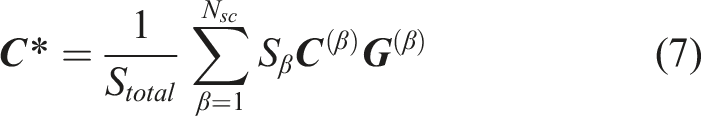
In PHFGMC-ANN proxy-surrogate model, pre-simulated mechanical stress-strain responses were generated using the Parametric High Fidelity Generalized Method of Cells (PHFGMC) to create an extensive multiaxial training database for the ANN micromodel. The PHFGMC has been established as an advanced micromechanical approach well-suited for analyzing the nonlinear and failure behavior of diverse periodic composite materials.25–29 To perform repeated nonlinear micromechanical analyses efficiently, the PHFGMC average virtual work formulation has been adopted to predict the nonlinear effective responses of the composite. The objective of the PHFGMC micromechanical method is to accurately predict the effective mechanical properties and the local elastic field within composites featuring periodic microstructure.5,30 In the PHFGMC method, periodicity conditions are enforced between the boundaries of a repeating unit cell (RUC). The RUC can be divided into general quadratic or hexahedral subcells representing the fiber and matrix phases. The average traction and displacement continuities are enforced between the subcells to achieve equilibrium. This approach is suitable for micromechanical computational analyses and enhances computational efficiency compared to the finite element method. 27
In contrast to the ductile behavior of metallic structures, which absorb impact energy through plastic hardening, composites exhibit energy absorption through diverse damage mechanisms. This phenomenon was observed in Low-Velocity Impact (LVI) events. Specifically in the aircraft industry, an impact event at a lower speed may cause visible or barely visible damage according to the literature31,32 and legacy data. Consequently, the LVI often initiates matrix cracking and delamination damages within the composite structure.33–37 As a result, the delamination between layers has the potential to significantly reduce the structural strength of the composite, particularly in terms of compressive strength.38–41
The design objective of hat-stiffened composite panels is to achieve a highly stiffened structure while adhering to minimal weight constraints based on conventional metallic designs. Hat-stiffened panels are manufactured by co-curing or co-bonding a skin to a hat-shaped stiffener.42,43 As a result, a separation between the skin and the stiffener was investigated for different applied loads, including the LVI and post-buckling.44–47 Resin fillets and fillers are used in composite structures to reinforce joints between various components, distribute stress concentrations, and provide additional surface area for bonding between composite components. Accordingly, the resin fillets are significant for preventing deboning in the skin-stiffener interface for T-shaped, 48 and hat-shaped stiffeners.49–51 Hence, resin fillets located in the inner corners between the skin and the stiffener were found to be a predominant factor in both experimental and numerical hat-skin deboning investigations, contributing to increasing the deboning threshold force. 52
In this research, the PHFGMC-ANN model was employed to predict the LVI response of carbon/epoxy hat-stiffened composite panels. The trained PHFGMC-ANN model capable of capturing the multiaxial nonlinear plane-stress responses has been implemented as a surrogate refined micromechanical model within a finite-element framework. The PHFGMC-ANN capabilities as the surrogate model have been applied to investigate the LVI of hat-stiffened composite panels. The simulations have been compared with experimental data from LVI tests conducted under various impact locations and energies. In addition, two different support conditions were applied in the tests: toggle clamps and pipe clamps. Furthermore, an investigation of the stiffened panels under compression loading (CAI) was simulated, and the results of the hat-skin separation were presented to predict the residual compressive strength after impact damage. The effect of resin fillets on the hat-skin delamination under impact loading has been investigated in this study. The analysis results have been compared against the experimental data to validate the ability of PHFGMC-ANN to predict the stiffened structure under impact and compressive responses.
Materials and methods
PHFGMC micromechanical model
The main goal of the PHFGMC micromechanical method is to predict the effective properties as well as the nonlinear material behavior and damage response of periodic composite materials.25,26 The formulation of the PHFGMC micromechanical method for analysis of composite materials presented in this manuscript is suitable for doubly-periodic multiphase material systems. Detailed formulations for the PHFGCM suited for doubly-periodic and triply-periodic microstructures have been developed over the years.
27
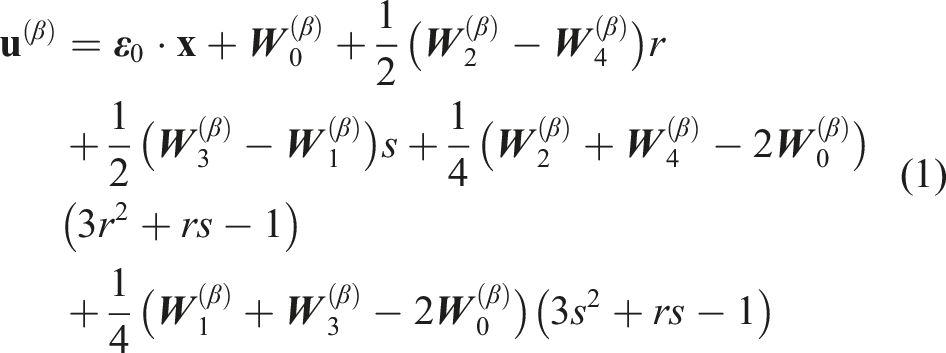
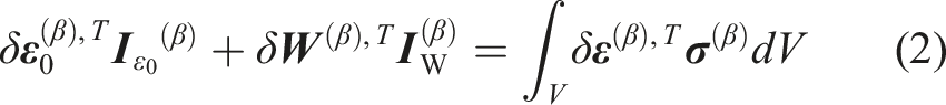
In this research, the PHFGMC average virtual work formulation has been adopted to predict the nonlinear effective responses of the composite. In the PHFGMC framework, the microstructure of the material system is identified within an RUC, which is divided into hexahedral-shaped subcells. Each subcell represents either the matrix or fiber phase, and its hexahedral shape contributes to efficiently representing the microstructure and geometry with a minimal number of subcells, as illustrated in Figure 1. A schematic representation of a doubly periodic material at the composite level (a). Given periodic composite material, a RUC can be isolated (b) and divided into arbitrary quadrilateral subcells (c). The mapping of a subcell from the physical to the parametrical coordinate system is illustrated in (d) and (e). 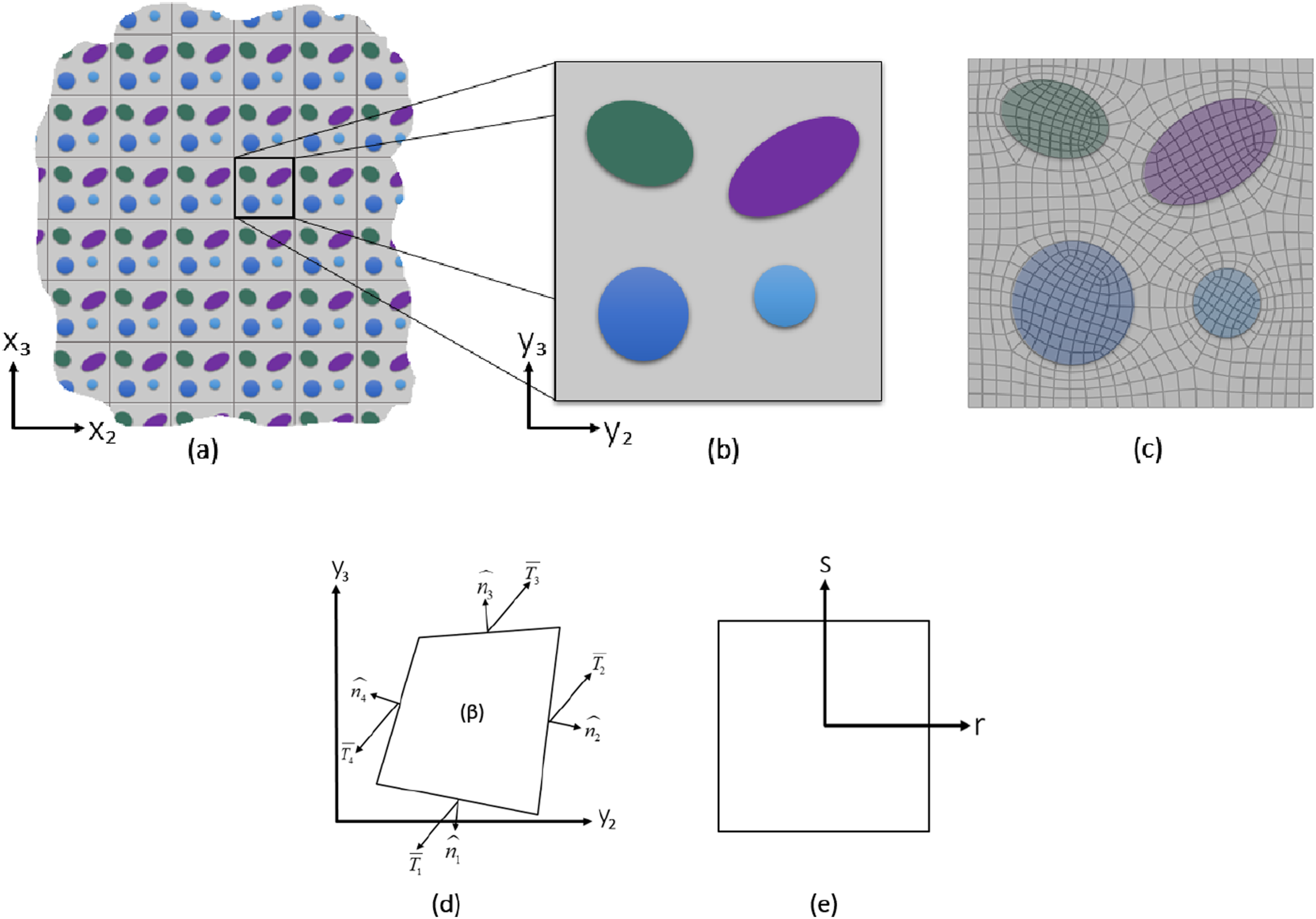
In the PHFGMC method, the composite material is described with respect to a global coordinate system
The following displacement expansion for subcell
Next, the external and internal virtual work balance for subcell

The coefficient matrix
In addition,

The generalized resisting force vector of the subcell includes two parts:
Following that, the matrix form of the equation (2) can be expressed by:
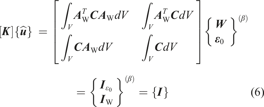
Therefore, the effective stiffness matrix
Proxy nonlinear PHFGMC-ANN for multiscale analysis
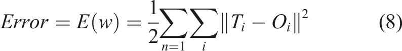
ANNs are used to identify complex relationships between inputs and outputs in a given data set and have an advanced optimization potential. Hence, the strength of ANNs lies in their ability to learn from data, adapt to changing patterns, and generalize the knowledge to make predictions on new unseen data. In the training process, the ANN computes the output of each neuron in the network through a series of weighted sums and activation functions, and the error between the predicted output and the actual output is calculated. The backpropagation learning rule adjusts weights using optimization algorithms to minimize the error. Those steps are repeated for multiple epochs until the network’s performance converges and reaches a satisfactory level. Following that, in the test process, a separate dataset is used to evaluate the trained network prediction capabilities. 24
Due to the complexity of the neural network learning process, the iterative learning procedure is used to solve the optimization problem of updating the weights. In the ANN program, developed by the authors, the algorithm used for updating the weights is the conjugate gradient method (CGM). In the training process, the CGM method updates the weights to minimize the total error function between the ANN outputs and the target outputs from the training data set. The error function is compared to a given error tolerance in every iteration. In addition, the developed ANN can be trained using the adaptive training method. This means that if the ANN cannot generate appropriate values compared to the target outputs within the given training epochs, the algorithm can change the structure of the ANN during training by adding more neurons in the hidden layers. The ANN initiates adaptive training if the calculated error exceeds the tolerance and the iteration count is below the specified maximum. New neurons are systematically added to each hidden layer during this adaptive training process to enhance the network’s capacity to learn complex patterns. These additions are made while ensuring that the weights of the existing neurons remain frozen, maintaining the previously learned information. Subsequently, all weights undergo adjustment through the CGM method, optimizing the network’s performance. This training continues until the total error reaches the tolerance.
The training is based on minimizing the sum of squares error (SSE) loss function:
The CGM is a numerical optimization technique that can be applied to train ANNs. As a second-order method, CGM incorporates momentum terms, aiming to identify the conjugate direction in which the gradient maintains its orientation. This ensures that continuing the next iteration in this direction does not spoil the results obtained in previous iterations.53,54
The first conjugate gradient
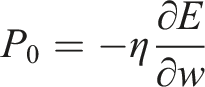
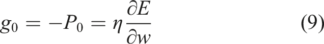
In this method, the minimization is performed in the conjugate direction, and its gradient
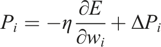

Therefore, it is calculated by:
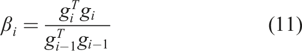
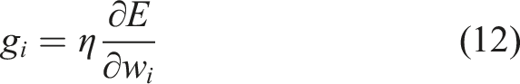
Therefore, the weights are updated by adding the current conjugate gradient to the weights from the previous iteration:

In this study, the architecture of the presented deep ANN model is configured with three inputs, featuring two hidden layers in a feedforward configuration, and three outputs. The inputs to the ANN represent the in-plane strain components, while the outputs represent the resultant stress components. The inputs and outputs of the ANN define different multiaxial loading paths, combining axial, transverse, and longitudinal shear. The strain path includes different applied multiaxial loads, with a total magnitude of around 2% strain. This enables the incorporation of the ANN as a constitutive model, effectively replacing the stiffness of the composite in models operating under plane stress conditions. The activation function for all neurons in the hidden layers is implemented as a sigmoid function. The training and test data sets are generated by the PHFGMC micromodel, providing multiaxial strain–stress responses for axial, transverse, and shear load combinations. The training dataset, consisting of over 10,000 data pairs, is divided into 80% for the training and 20% for validation. The prediction (test) data set includes different applied multiaxial loading paths that were not part of the training dataset. The accuracy of the converged ANN prediction was evaluated by assessing its capability to forecast the stress-strain response of the PHFGMC under varied applied strain loading paths.
The chart in Figure 2 visually represents the integration of multiscale analysis with the PHFGMC-ANN constitutive surrogate modeling. The training and testing datasets are achieved from PHFGMC RUC simulations for different multiaxial load combinations of axial, transverse, and longitudinal shear representing the lamina. While open-source codes are now available, we employed an in-house code to train the ANN based on a CGM backpropagation algorithm to minimize the loss function. The converged weights from the backpropagation CGM deep learning algorithm are used to carry out the trained ANN in a feedforward mode and can be embedded as surrogate constitutive incorporated into the ABAQUS commercial explicit-FE code. This proposed PHFGMC-ANN model is valuable within structural simulations for nonlinear constitutive computations. To achieve effective utilization, a critical preliminary step involves conducting a relatively small yet strategically significant set of pre-simulations using the PHFGMC micromechanics. Conducting these preliminary simulations is essential for creating the necessary datasets for training and verifying the ANN. However, following the completion of the ANN’s training and testing phases, the PHFGMC-ANN transforms into a specialized tool dedicated to the specific material system. It is then ready for application as a surrogate constitutive model across a diverse spectrum of structural finite element simulations. Within the surrogate modeling framework, the refined micromechanics is replaced by a proxy-trained ANN that delivers the required local nonlinear responses, from pre-simulated micromechanics to the finite element incremental solver. The model aims to represent the nonlinear constitutive behavior of a unidirectional lamina to be integrated within an FE analysis of layered-shell or 3D-shell elements. Based on the classical laminate theory, the laminae are modeled in structural analysis as thin plates under the assumption of plane-stress conditions. The PHFGMC-ANN nonlinear model is incorporated into the ABAQUS commercial explicit-FE code. Technically, the PHFGMC-ANN assumes the role of the material subroutine VUMAT, which is responsible for generating the constitutive model for a single unidirectional lamina in its local coordinate system. Cohesive surfaces are strategically placed at the interface between every two adjacent plies to accurately capture delamination response and out-of-plane damage. These surfaces adhere to traction-separation laws, which define damage evolution by quantifying the fracture energy needed for failure post-damage initiation. Specifically, the traction-separation law follows a linear softening stress-strain response after damage initiation. Integration of the PHFGMC-ANN micromodel into multiscale structural analysis for LVI.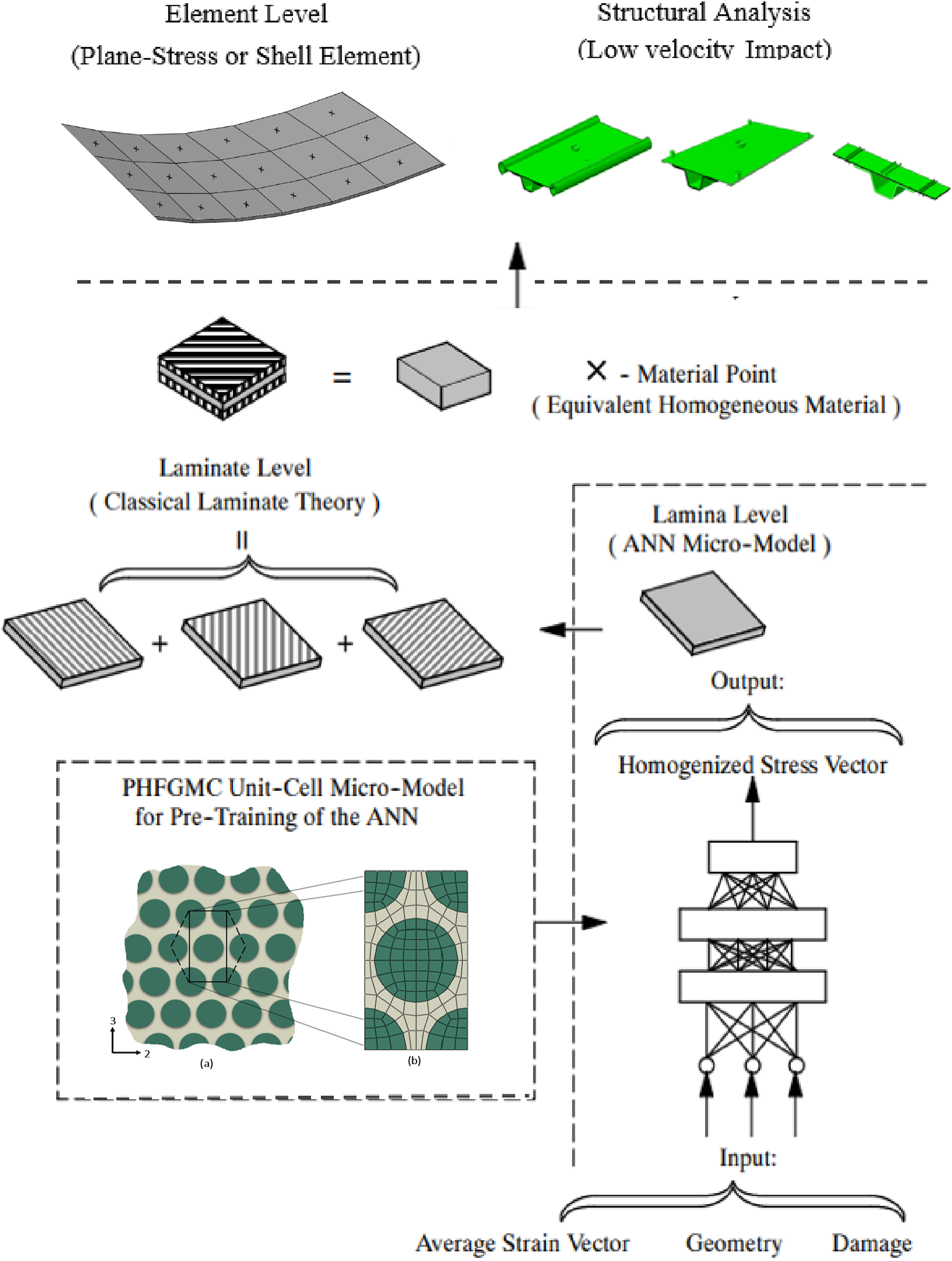
Material system
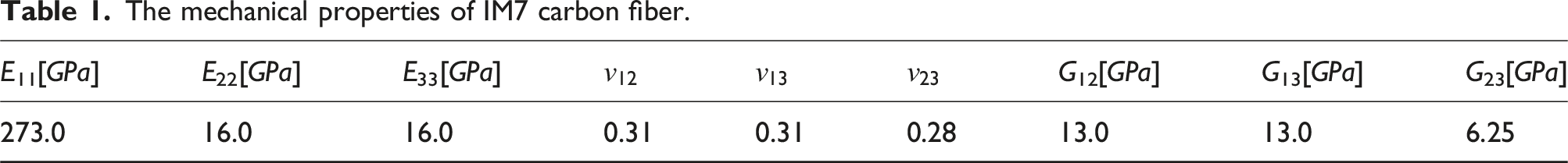
The mechanical properties of IM7 carbon fiber.
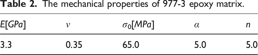
The mechanical properties of 977-3 epoxy matrix.
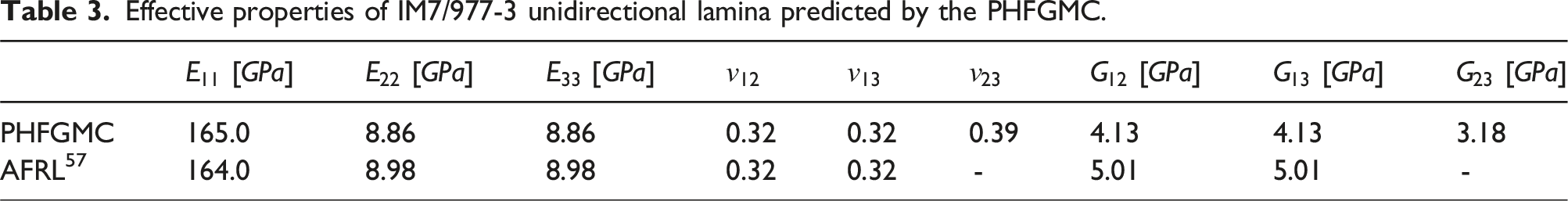
Effective properties of IM7/977-3 unidirectional lamina predicted by the PHFGMC.
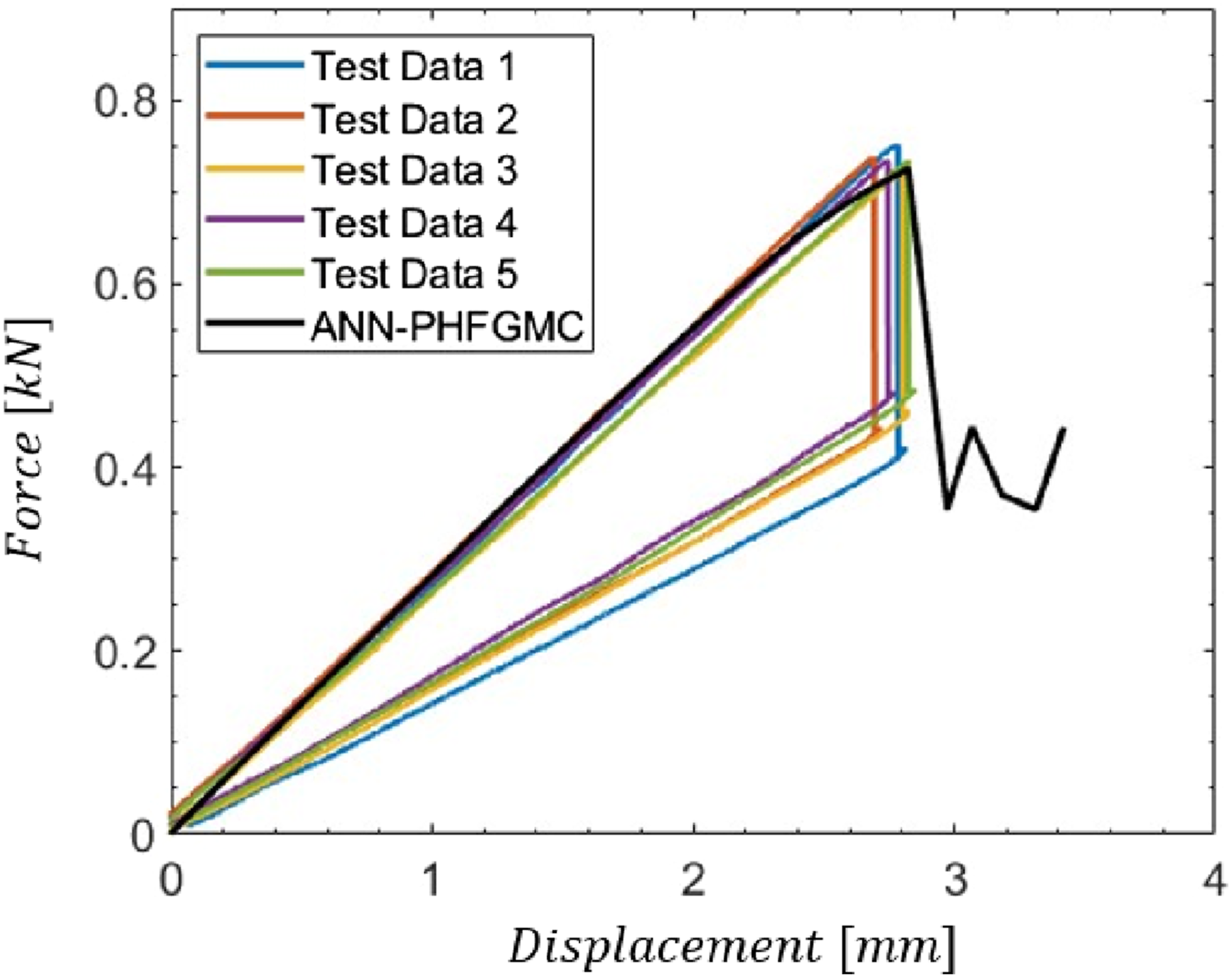
Force/displacement curves from ENF. 57
Results and discussion
Low-velocity impact of single hat-stiffened panels
The LVI experiments and c-scans were performed at AFRL. Six stiffened panels of 311 mm × 197 mm (12.25″ × 7.75″) were tested, three of the specimens were placed on roller support pressed down using toggle clamps for simply-support conditions. The other three specimens were placed into pipes that were held by toggle clamps.
59
Three different impact locations were tested; center of the plate (mid-plate) 35J impact, 64 mm (2.5″) from the centerline (mid flange) 35J impact, and 46 mm (1.8″) from the centerline (edge-flange) 25J impact. The isometric views of the model offer enhanced comprehension of the boundary conditions and the locations of impacts. These visualizations are presented in the first row of both Figures 4 and 5. (a) Test setup: top toggle clamps (simply-supported panel), and (b) mid-flange LVI test. LVI simulation results for the simply-supported stiffened plates compared to experimental results 59. The finite element model isometric view, force-time and force-displacement responses are shown for (a) 35J mid plate impact, (b) 35J mid flange impact and (c) 25J edge flange impact.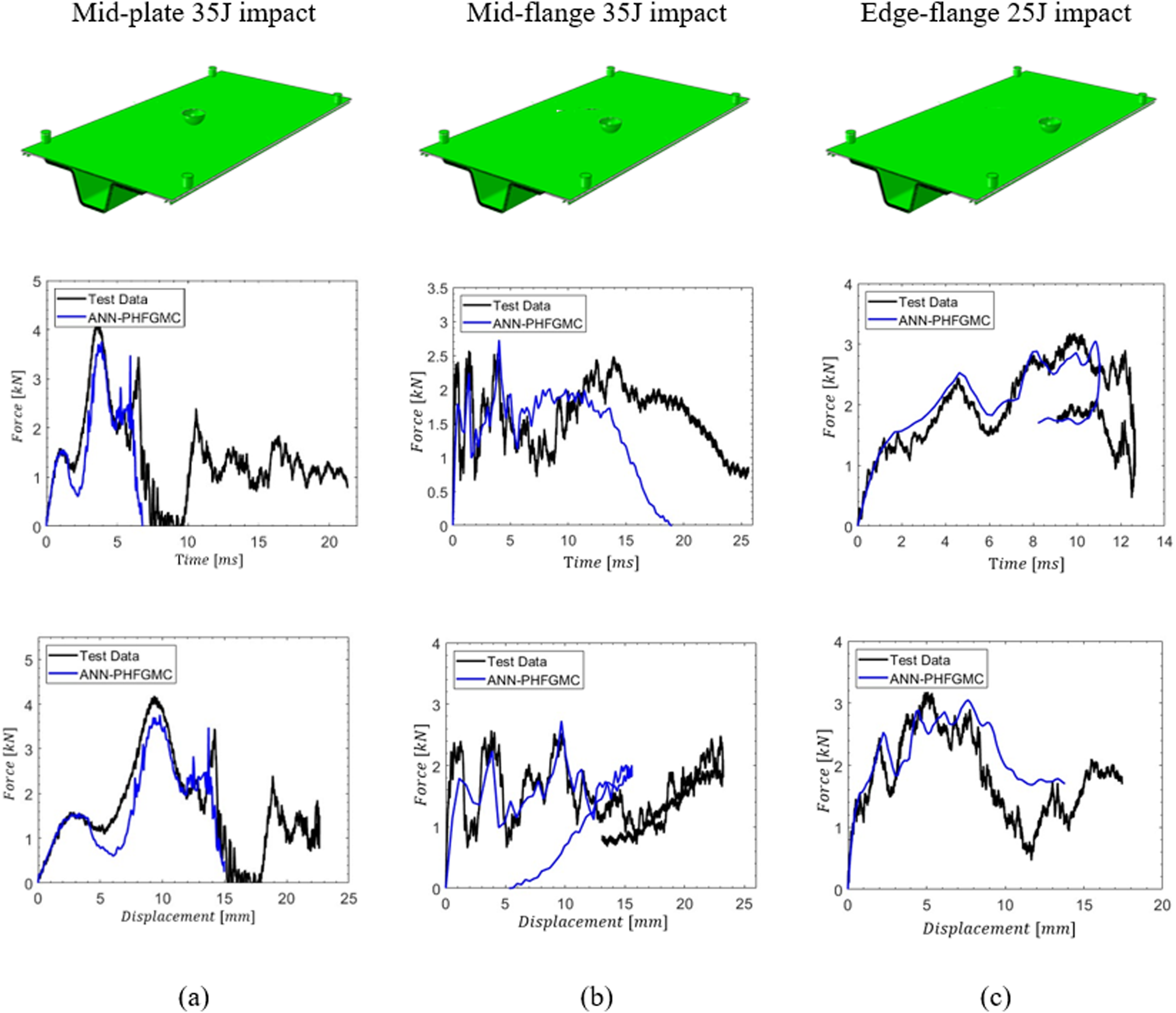
The cohesive surface properties. 61
In addition, the impactor diameter was 25.4 mm (1″), and its weight was 8.53 kg. The initial velocity of the impactor was determined based on its kinetic energy and was applied as a the initial velocity of the impactor. The impactor and the metallic parts of the clamps were modeled as rigid bodies. The specimens were placed on fixed roller support pressed down using toggle clamps for simply-support condition. The top-toggle clamps’ rubber elastic properties were
60
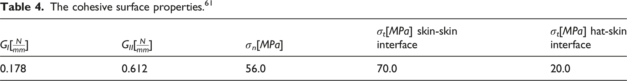
hat-skin delamination in simply-supported stiffened plates is illustrated for (a) 35J mid plate impact, (b) 35J mid flange impact and (c) 25J edge flange impact. Side views of the impacted plates at the peak-moment of the impact are shown, followed by hat-skin cohesive damage pattern from the analysis results (the damage pattern shown in red), and c-scans of the panels (the damage pattern shown in dark gray).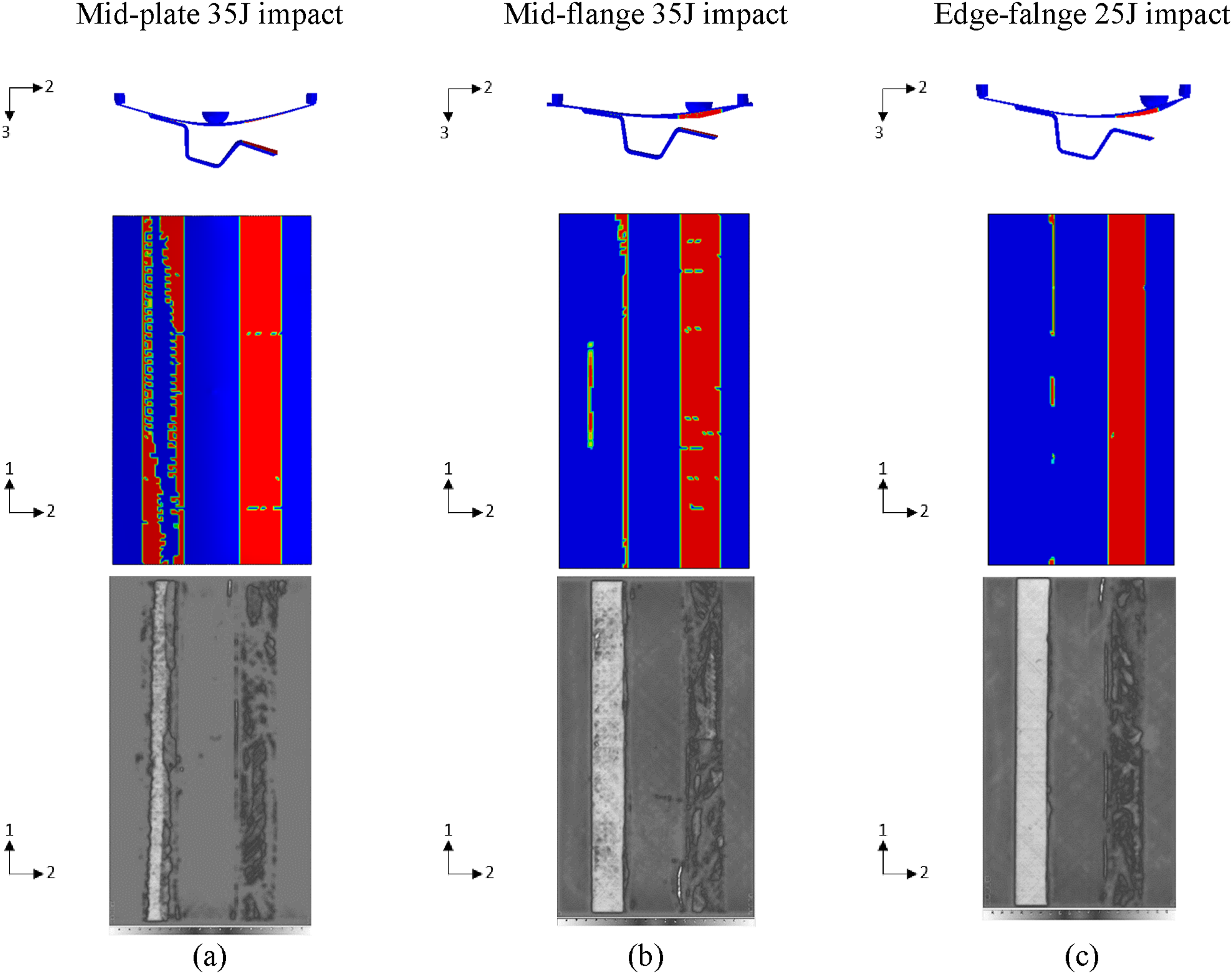
The load-time and load-displacement responses of the LVI simulations for the three simply-supported clamped panels are shown in Figure 7. The simulation results were compared to drop tower test results. In all of the simulations presented, the initial part of the force-time and force-displacement responses was associated with boundary conditions, and the analysis results with the refined PHFGMC-ANN were in good agreement with the experimental results. However, in the latter part of the experiments, substantial panel deflection was observed, especially in the mid-flange impact test. This deflection occurred following the hat debonding from the skin. Although the large deflection was not entirely captured by the PHFGMC-ANN-based analyses, the overall response was adequately captured. In addition, during the mid-plate impact test and the edge-flange impact test, the impactor after the first impact was not restrained mistakenly, and a double hit was observed, while the simulation had a single impact for all three cases.
The delamination damage patterns from the analyses were compared against the ultrasound c-scans of the damaged plates, and the results are presented in Figure 5. The deformed geometries of the finite element simulations are presented in side view, and the top view of the delamination damage patterns from the analyses appear in red. In the c-scans, the damaged areas can be identified by the dark gray areas. For all three impact cases one flange of the hat was fully debonded from the skin (right flange in the images), while the left flange remained bonded to the skin surface. In the mid-plate impact, the left flange was partially damaged in both experimental and analysis results. The mid-flange and edge-flange impacts kept the left flange almost fully bonded and only a small damaged areas appeared. Therefore, the PHFGMC-ANN simulations produced results in good agreement with experimental data with respect to hat-skin separation and delamination pattern. LVI simulation results for the pipe-clamp conditions compared to experimental results
35
. The finite element model isometric view, force-time and force-displacement responses are shown for (a) 35J mid plate impact, (b) 35J mid flange impact and (c) 25J edge flange impact.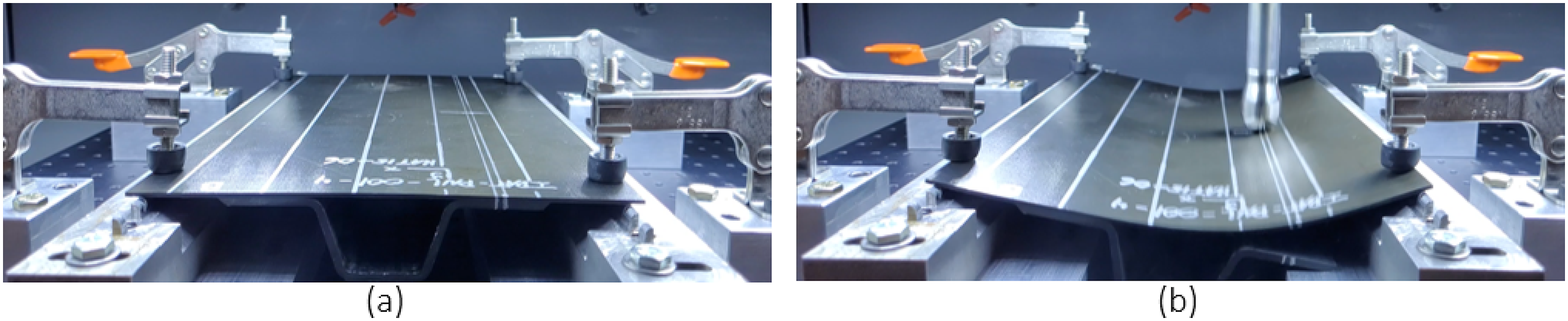
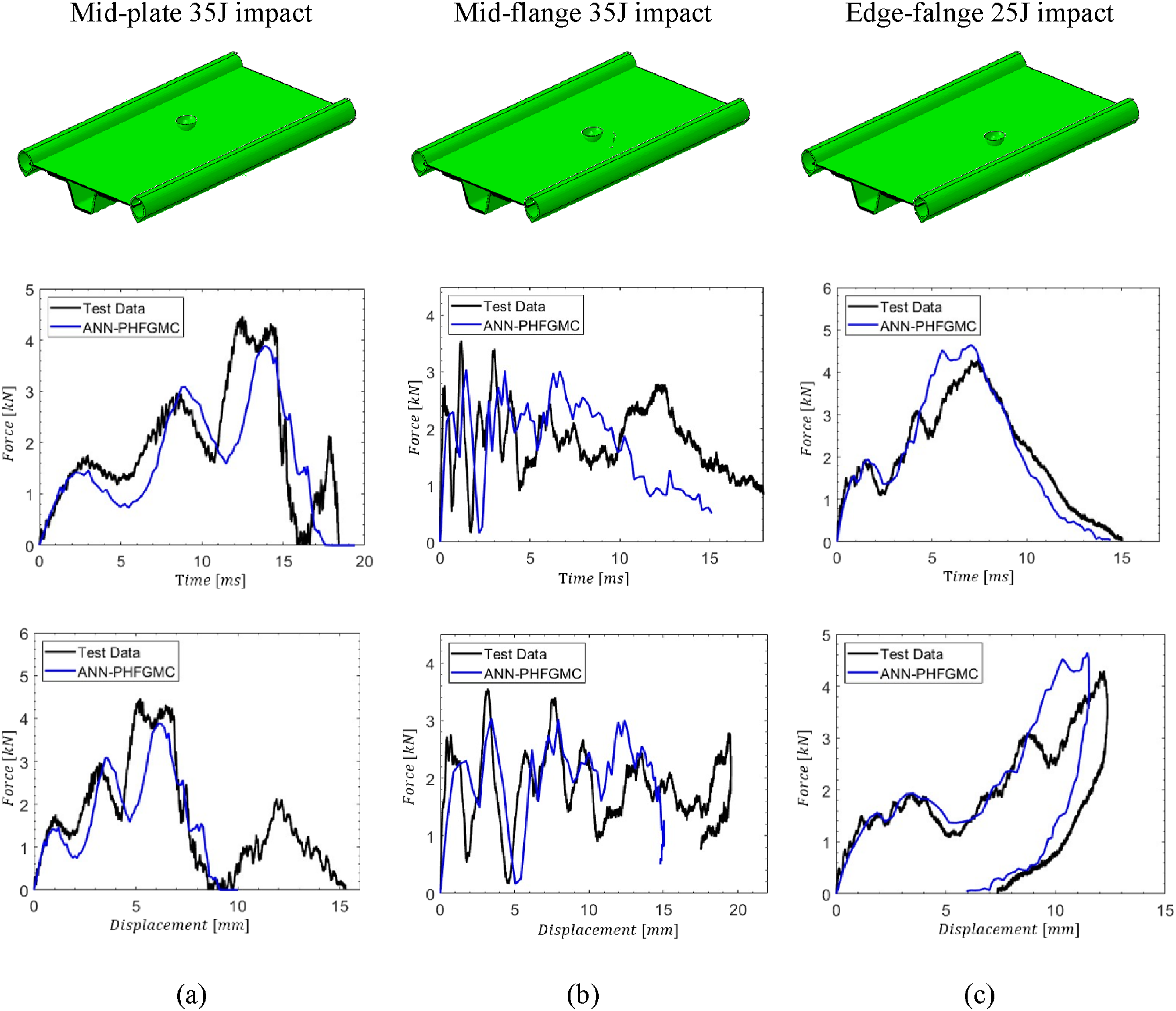
For the pipe-clamped conditions, the metallic pipes were modeled as rigid bodies, clamped between the top fixed flat support and “v” shaped fixed support at the bottom. Three different impact locations were tested in and simulated for the pipe-clamped support panels: center of the plate (mid-plate) 35J impact, 2.5″ from the centerline (mid-flange) 35J impact, and 1.8″ from the centerline (edge-flange) 25J impact.
The load-time and load-displacement responses of the LVI simulations for the three pipe-clamped panels are shown in Figure 4. It should be noted that the mid-plate and mid-flange impact experiments observed double hits, whereas the analyses simulate only a single impact. This constitutes the primary reason for the observed differences between the experimental and simulated results in the latter sections of the force-time and force-displacement graphs: the second dominant peak of the force-time is a result of the second hit, and as a result, the matching force-displacement graphs show another peak in the loading before the unloading. Nevertheless, similar to the simply supported simulation results, the simulations accurately predicted the experimental results in the initial segments associated with boundary conditions in all three cases. However, it’s important to recognize that a limitation of the presented results is the execution of only a single LVI experiment for each case discussed. Conducting repeated LVI experiments could enhance the validation of the simulations.
The delamination patterns compared to the c-scans are presented in Figure 8. According to the scans, one flange (the right flange in the images) was fully separated and debonded from the skin in the mid-plate and mid-flange tests, while the other stiffener flange remained almost undamaged. Those results were fully captured in the PHFGMC-ANN analyses. The damage pattern in the edge-flange case was larger than the delaminated area captured in the scans. It is possible that the damage progressed more rapidly in the analysis than in the experiment, diverging from the impact location, leading to the development of damage in an asymmetrical manner. In contrast, in the analysis, the impact location is ideal, and the damage developed symmetrically on both sides of the model. Furthermore, when comparing the delamination pattern between the simply-supported and pipe-clamped panels, the smallest skin-hat delamination was observed in the pipe-clamped panel in the edge-flange impact case. This phenomenon can be explained by the pipe clamps offering support along the entire length of the panel’s edge. In contrast, the simply-support condition supports the panel from the corners, allowing the skin-hat damage to propagate. Hat-skin delamination for the pipe-clamp conditions is shown for (a) 35J mid plate impact, (b) 35J mid flange impact and (c) 25J edge flange impact. Side views of the impacted plates are shown at the peak-moment of the impact, followed by hat-skin cohesive damage pattern from the analysis results (the damage pattern shown in red), and c-scans of the panels (the damage pattern shown in dark gray).
Compression after impact of single hat-stiffened panel
The CAI experiments were conducted at the AFRL with pipe-clamped impacted hat-stiffener panels for the three cases: mid-plate 35J impact, mid-flange 35J impact, and edge-flange 25J impact tests. After the LVI analyses were performed with PHFGMC-ANN, CAI simulations were carried out using the LVI end-increment effective material properties. The finite element model boundary conditions were fixed in the bottom nodes of the stiffened panels,
The analyses results compared to the experimental results are shown in Figure 9. The mid-plate CAI test results were similar to the mid-flange CAI test result, where the failure load levels were observed at Schematic CAI model (left image). The CAI analyses force-displacement results are compared to CAI experimental results for three pipe-clamp conditions.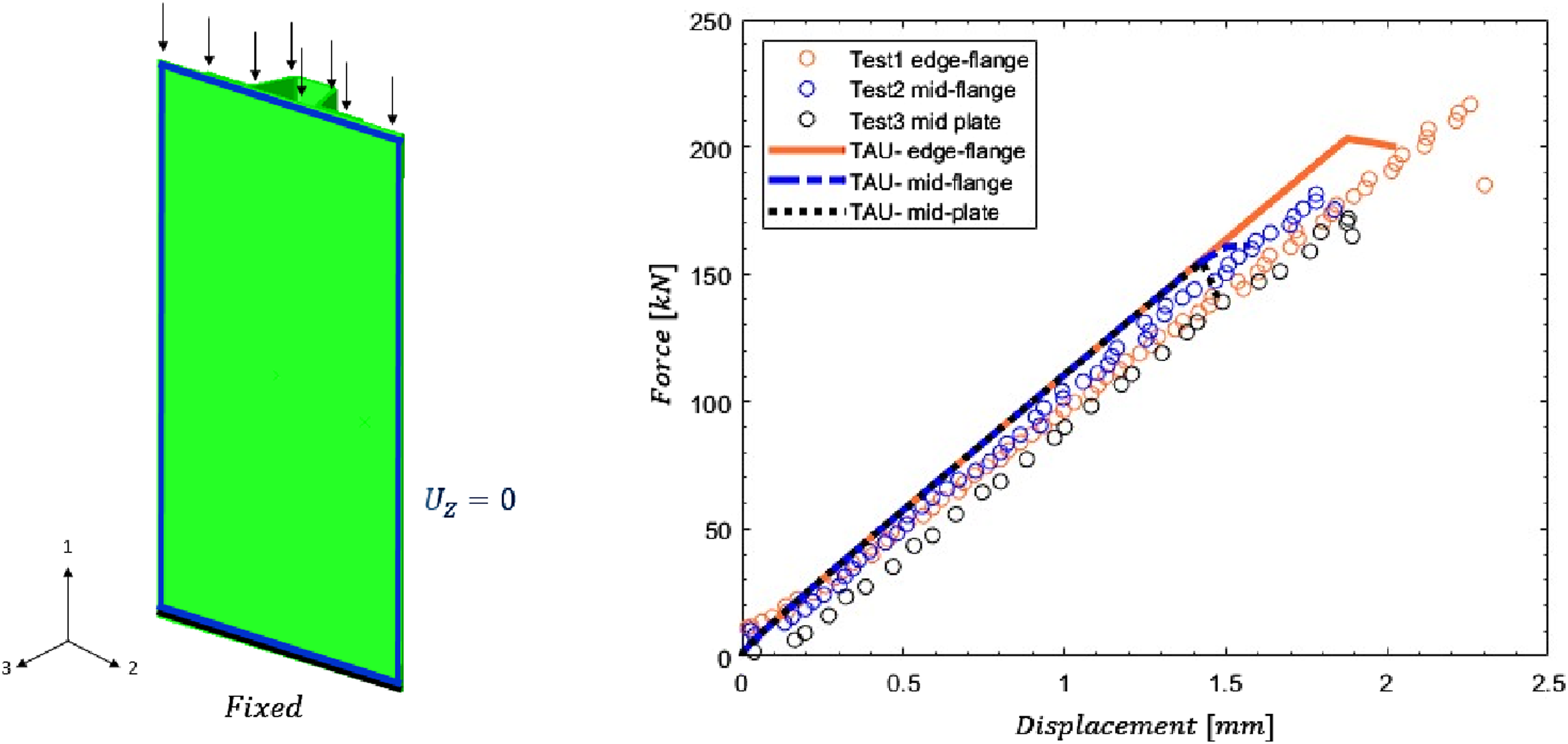
In addition, the slope of all force-displacement experimental responses did not change, so there was no evidence of pre-buckling before the failure. Hence, a possible reason for the difference between the models is the partial separation of the stiffener from the skin in the edge-flange model, while in the other two models, one side of the hardener is completely separated from the plate.
Low-velocity impact of single hat-stiffened coupon: fillet size and damage responses
Coupon-level test elements of 38 mm × 197 mm (1.5″ × 7.75″) excised from a single-stiffener panel were tested for mid-plate 5J impact. A schematic LVI single hat-stiffened coupon is shown in Figure 10. The skin stacking sequence was Schematic single hat-stiffened LVI coupon.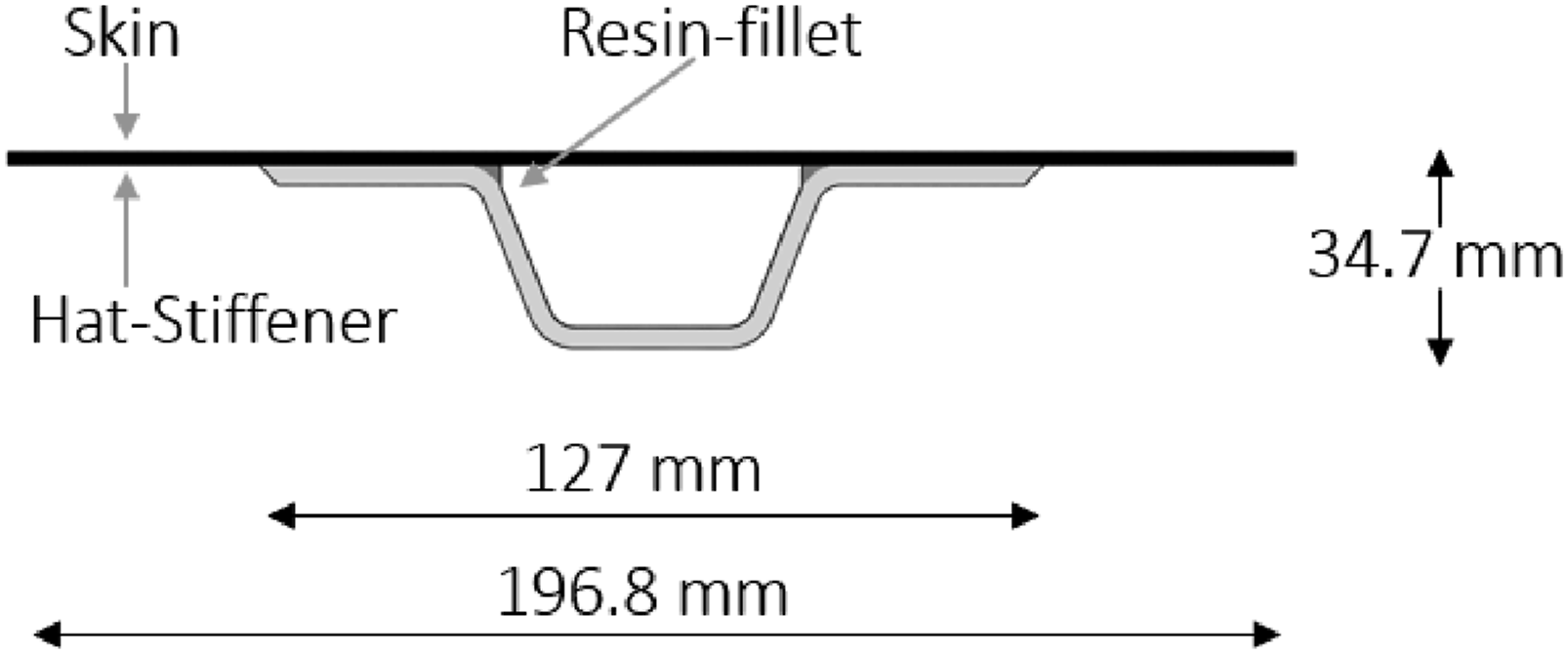
For the modeling approach, the PHFGMC-ANN model was integrated as the skin surrogate-constitutive model, and the hat mechanical properties were defined by the effective elastic properties. The average mesh size in the model was 1 mm × 1 mm. The impactor and the clamping rollers were modeled as rigid bodies, and the clamping rollers were fixed for the model boundary conditions. The analysis results are shown in Figure 11. The analysis result shows very good agreement with test results for both force-displacement response and hat-skin damage pattern. Additionally, the presence of an inner epoxy fillet within the hat-skin interface influenced the hat-flange debonding, aligning with the experimental observations where the separation progressed from the outer edge of the flange towards the inner corner. Despite its small size and negligible strength in comparison to the composite’s effective strength, the influence of the resin filler proved to be a critical factor. This significance may be attributed to the geometrical impact of the resin fillets on the bending behavior of the skin. It was observed that the panels without these fillets exhibited more substantial bending, resulting in greater deflection in the non-stiffened section at the mid-point of the specimen. Consequently, a stress concentration was manifested in the inner corner between the hat and the skin. PHFGMC-ANN hat-stiffened coupon analysis compared to test results
62
and damage propagation in the hat-skin interface.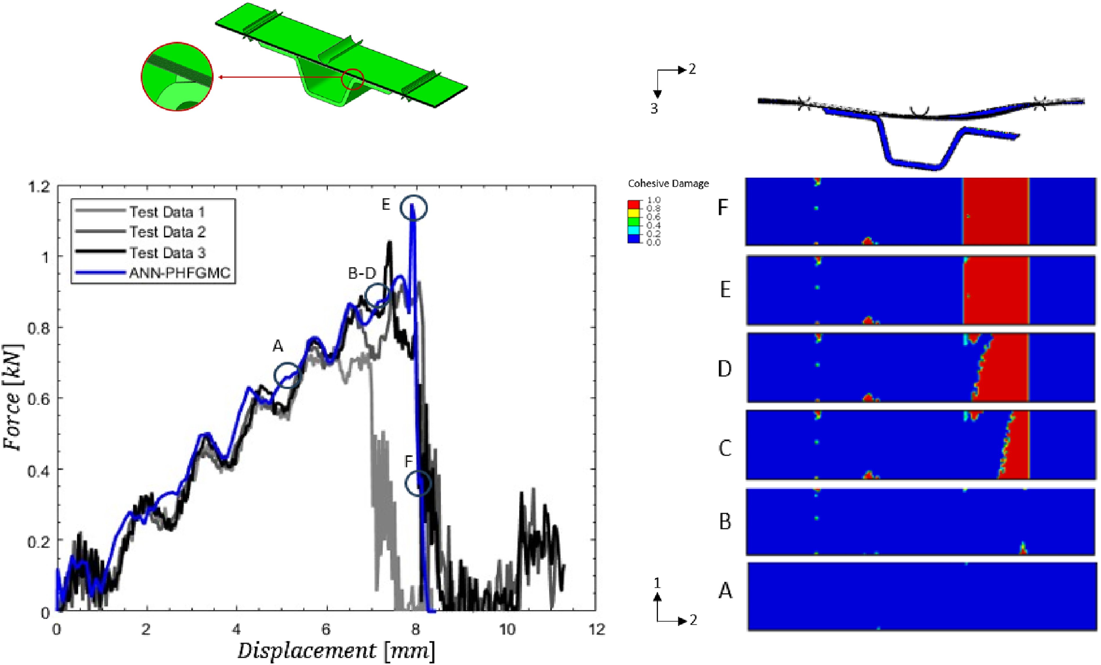
Figure 12 shows further investigation of the inner-fillet size effect. Four filet sizes were simulated between 3 mm and 6 mm resin fillet length. As a result, different fillet sizes influenced the force-displacement strength of the models. In addition, the damage and separation of the hat from the skin propagated from the outer corner of the hat flange to the inner corner of the flange, similar to the experimental observations. Size-effect of resin fillets in the hat-skin inner corner interface.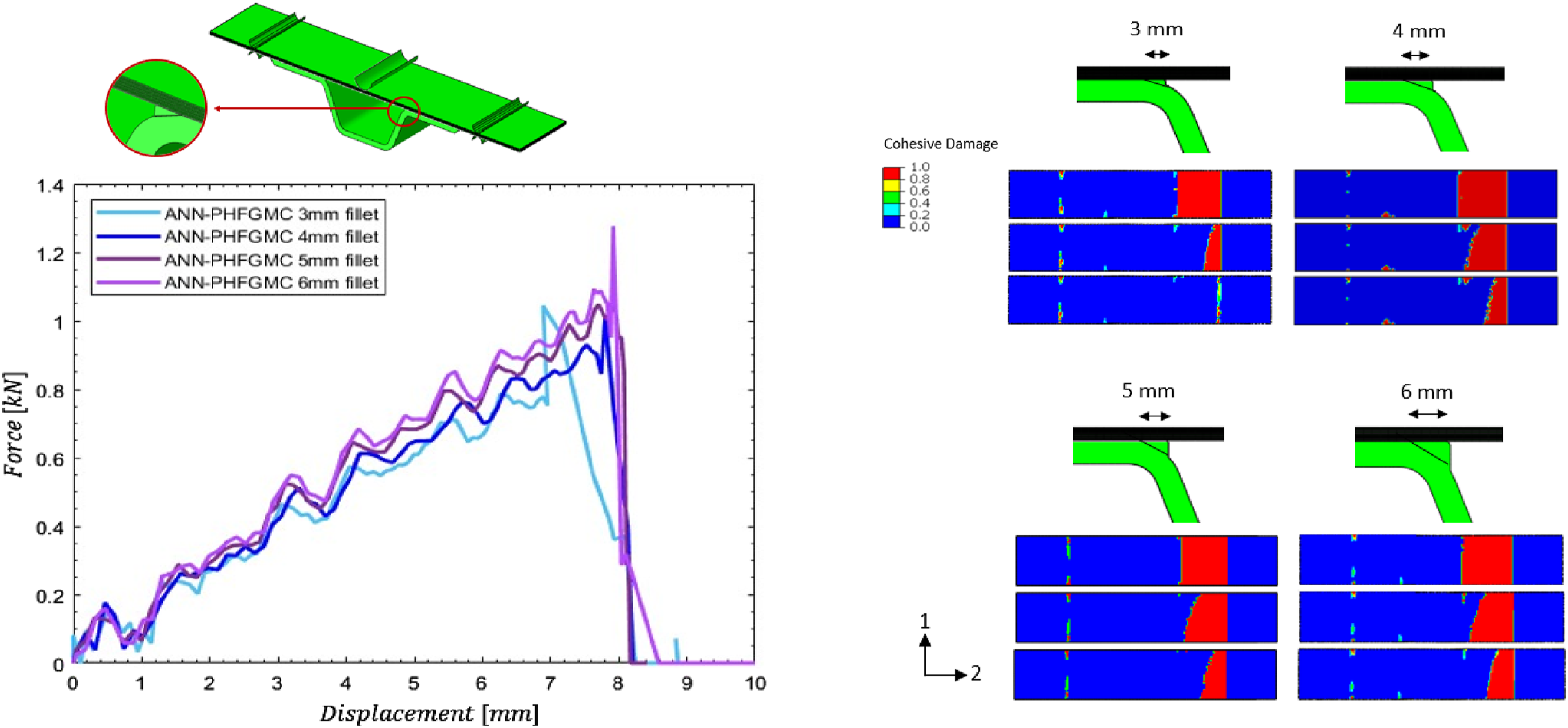
Conclusion
A new PHFGMC-ANN reduction modeling approach is presented for integrating the PHFGMC refined micromechanics in a multiscale analysis of composite structures. The PHFGMC-ANN surrogate model discussed in this manuscript was used to investigate the LVI of hat-stiffened laminated composite panels. The PHFGMC was used to generate the needed ANN training database for the effective nonlinear micromechanical response of a hexagonal RUC. The trained and verified PHFGMC-ANN model was integrated into analyses of single hat-stiffened laminated composite panels under various impact locations and energies, considering two different support conditions. Further exploration of stiffened panels included CAI simulations and LVI analyses of hat-stiffened coupons. The analysis results displayed good agreement compared to the experimental results. The hat-skin interface debonding analysis results were compared to the ultrasonic c-scans of impacted test panels. The parametric investigation of the resin fillet justified the modeling consideration and inclusion in the bonded structures, as it predominantly influenced the hat-skin interface separation.
Footnotes
Acknowledgments
The advancement of research presented in this paper is based upon a collaboration between the Air Force Research Laboratory, University of Michigan, and Tel. Aviv University under a joint research agreement. The views and conclusions contained herein are those of the authors and should not be interpreted as necessarily representing the official policies or endorsements, either expressed or implied, of the U.S. Air Force or the U.S. Government. The last author acknowledges the additional support by the Nathan Cummings Chair of Mechanics at Tel. Aviv University. Cleared for public release - Case Number: AFRL-2024-0475.
Declaration of conflicting interests
The author(s) declared no potential conflicts of interest with respect to the research, authorship, and/or publication of this article.
Funding
The author(s) received no financial support for the research, authorship, and/or publication of this article.
Data availability statement
Data sharing not applicable to this article as no datasets were generated or analyzed during the current study.