
Abstract
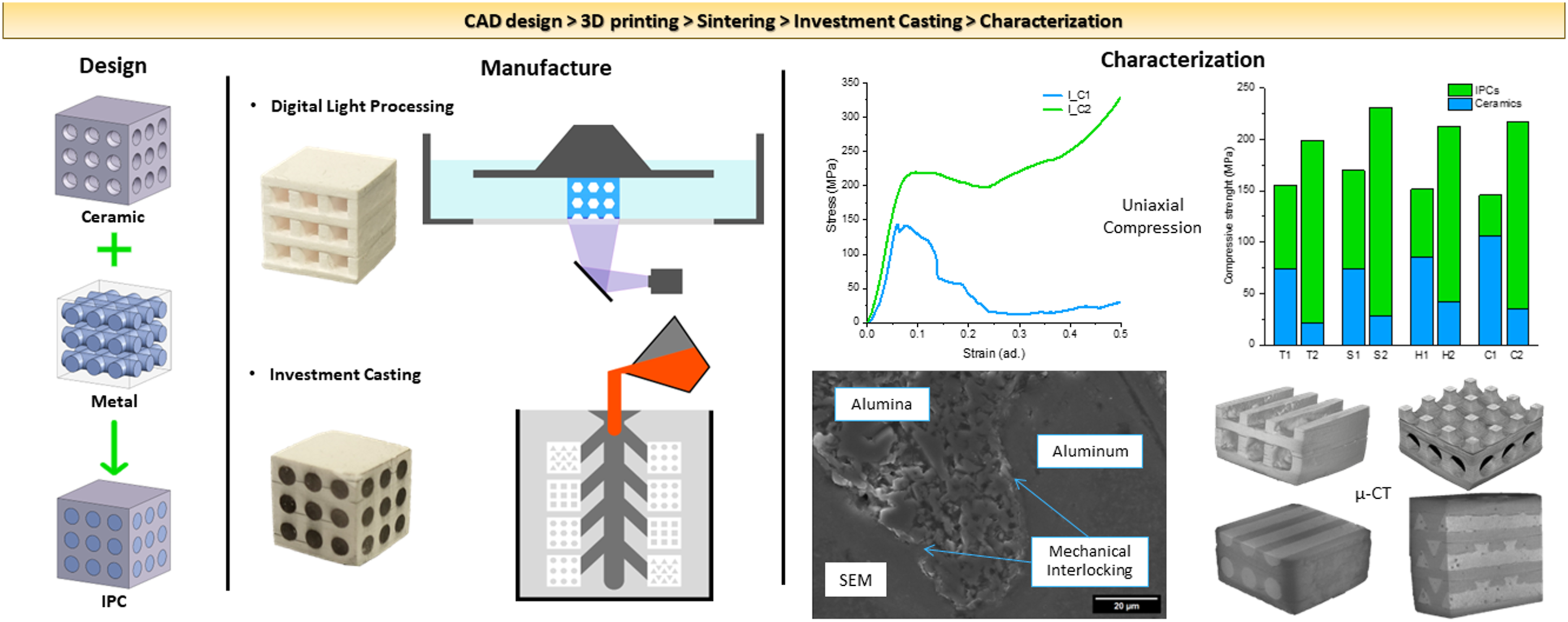
Additive manufacturing (AM) technologies are unleashing the restrictions imposed by conventional manufacturing, allowing the production of innovative designs tailored to improve properties or performance. AM techniques in ceramic production allow the application of novel designs to ceramic parts, opening new opportunities for combining technologies aiming to obtain architected interpenetrating phase composites (IPCs). In this study, alumina structures with different architectures and Computer Aided Design (CAD) structure porosity oriented unidirectionally or bidirectionally, were fabricated by vat photopolymerization technique, namely Digital Light Processing. Afterwards, these structures were infiltrated with an aluminum alloy through investment casting, thus obtaining aluminum-alumina IPCs. Under compression, the IPCs presented a ductile behavior, conversely to the fragile ceramic counterparts. The IPCs compressive strength and absorbed energy were expressively higher than their ceramic counterparts. Comparing the bidirectional IPCs with the unidirectional ones, a significant increase in compressive strength and absorbed energy was observed, from 36.2% to 42.3% and from 164.8% to 358.1%, respectively, due to the greater amount and interconnection of the metal inside the ceramic structure. This study demonstrates the feasibility of this manufacturing route, combining two distinctive technologies, for the fabrication of metal-ceramic architected IPCs, allowing to tailor their mechanical properties and energy absorption capacity for a given application.
Keywords
Introduction
Composite materials consist of two or more distinct phases with a clear interface, where their properties will depend on the nature of each phase as well as the degree of connection across the interface between them. These materials typically consist of an isolated reinforcing phase dispersed within a continuous phase. Conversely, Interpenetrating phase composites (IPCs) consist of two or more topologically continuous and three-dimensionally interconnected phases. 1 As a result, each phase heavily contributes to the final properties of the IPC, enabling a combination of distinct properties unattainable by a solo material.2,3 Multiple combinations of materials have been studied for IPCs, including metal-polymer IPCs,4,5 polymer-polymer IPCs, 2 and metal-ceramic IPCs.6,7,8 In fact, metal-ceramic IPCs demonstrate great potential due the sum of characteristic phase properties. The ceramic phase provides the material with high hardness, wear resistance, and stability at high temperatures, while the remaining ductile metal phase enhances fracture toughness and thermal conductivity.9,10 This set of properties render metal-ceramic IPCs suitable for demanding applications like braking systems, cyclic fatigue scenarios, high-temperature applications, vibration damping, and lightweight armor.3,10
Multiple studies proved that the spatial distribution of the different phases of the IPCs significantly impact their properties.6,11,12,13 IPCs with the phases interconnected randomly in space can introduce undesired anisotropy and uncertainties in predicting their properties. 2 Conversely, IPCs with an architected interconnected spatial distribution enable a higher control over the composite properties, as they can be tailored for each application through material distribution optimization. 2 While IPCs with randomly distributed phases have been fairly explored in the literature, research on architected IPCs remains limited. 2 Several types of lattice structures have been used to manufacture architected IPCs due to the interconnected network of solid struts or shells that cover the 3D space.14,15 These structures can be used to modify mono-material parts properties by controlling the unit cell typology and arrangement, 16 and are being explored for several applications, as metallic structured prostheses with lower stiffness, allowing fluid flow and vascularization due to their porosity17,18; high weight-to-strength ratio and thermal conductivity aeronautic parts 19 or even deformation and collapse-controlled structures for impact and energy absorption. 20
Typically, metal-ceramic IPCs are manufactured through infiltration-based techniques that fill the voids of porous ceramic structures with metal. The development of Additive Manufacturing (AM) technologies for ceramics fabrication has been growing, 21 being robocasting, 22 binder jetting, 23 and stereolithography 24 the most explored for complex ceramic parts fabrication. Compared with conventional ceramic production methods, AM technologies present some advantages, such as higher design freedom, elimination of the need for molds, and short production cycles.25,26 Digital Light Processing (DLP) is a vat photopolymerization AM technology, whose fabrication principle for ceramics relies on the photopolymerization of a ceramic-loaded resin. Light in the UV range passes through a Digital Multimirror Device (DMD) that will project the layer to be polymerized, according to the previously obtained STL file of the part to fabricate. With the first layer printed the build platform will rise and the next layer will start to be printed. 17 DLP high control over the geometric deposition of the material during production allows to obtain parts with higher geometrical and dimensional accuracy. One of the technologies that can infill ceramic structures with a metal alloy is investment casting, a conventional precision casting technology that can produce complex geometries with excellent surface finish and dimensional and geometrical accuracy. This technology is largely used for jewelry fabrication, and complex pieces like airplane turbines. 27
In this study, architected aluminum-alumina IPCs were manufactured through a combination of distinct technologies. DLP was used to fabricate alumina structures that were subsequently filled with an aluminum alloy by investment casting. Different geometries were explored for the fabrication of the ceramic structures, giving rise to different spatial materials distributions and metal/ceramic volume ratios in the IPCs. Morphological and mechanical characterization was performed on both the alumina structures and IPCs.
Materials and methods
Materials
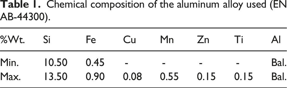
Chemical composition of the aluminum alloy used (EN AB-44300).
Methods
Ceramic structures fabrication
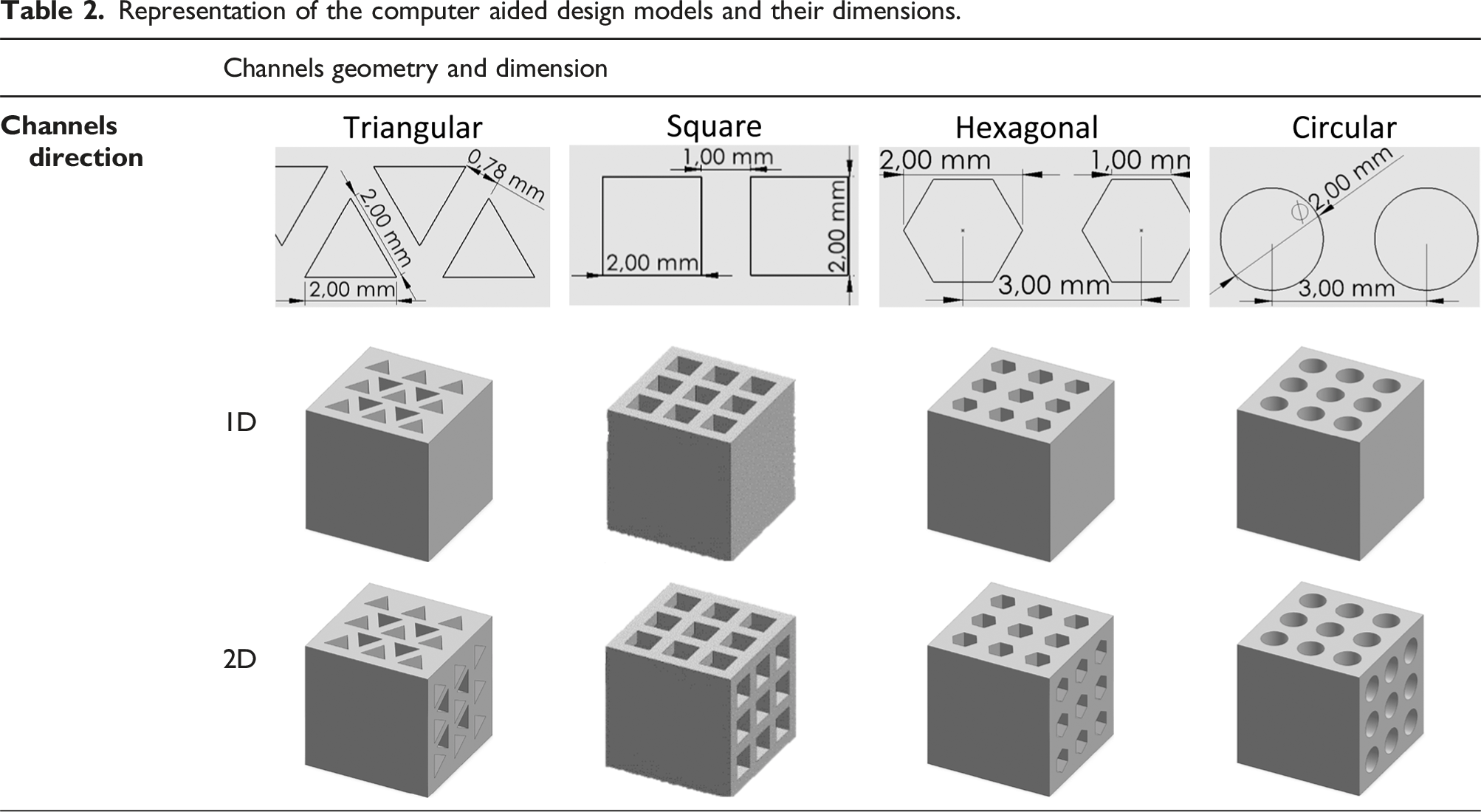
Representation of the computer aided design models and their dimensions.
The specimens were printed by DLP technology using the Tethon 3D Bison 1000 printer (Tethon 3D, USA), which uses a LED wavelength of 405 nm. The processing parameters for printing are detailed as follows: Layer thickness of 100 µm; exposure time per layer of 180s; chamber temperature of 40°C; Light intensity of 2 mW/cm2.
After DLP printing, the parts go through a thermal cycle that starts with a burn-out step that takes place during a controlled heating till 500°C, for polymer debinding, followed by an ensuing heating and a stage at 1600°C for 2 hours, promoting the sintering of the ceramic part.
IPCs fabrication
The IPCs were manufactured through the combination of investment casting and DLP. The process begins with the construction of an assembly tree that integrates the previously DLP manufactured alumina structures (sintered), by covering them with a thin layer of commercial investment casting wax (R35WF from Goodwin Refractory Services Ltd.). This wax has a melting point of 70°C and a burning temperature of 200°C. Subsequently, the plaster mold that is used to form the empty cavity in which the metal flows, during investment casting, is prepared. The process starts by positioning the wax pattern inside a metal cylinder and preparing the plaster by adding 40 wt% plaster powder (SRS Eurovest jewelry investment powder) to water until a homogeneous slurry is formed. Afterwards, this mixture is poured into the cylinder where the wax pattern was placed. After a resting time of 2 hours, the mold goes through a thermal cycle on a furnace, for water evaporation, wax decomposition, and to harden the plaster.
The last step for obtaining the proposed IPCs is the casting, done on an Indutherm VC400 F equipment. This procedure started by setting the temperature set point for melting the aluminum, at 650°C. The use of a higher temperature in the casting process than that of the aluminum alloy (570°C) will prevent the occurrence of porosity on the cast. Afterwards, the aluminum alloy was added to the crucible, and the casting was continued when the mold was in position (being at 350°C), with an applied pressure of 1 bar. Finally, the excess aluminum is cut, and the samples were polished for subsequent characterization. A diagram with the crucial steps to manufacture the aluminum-alumina IPCs is presented in Figure 1. Diagram that presents the crucial steps in the manufacture of the proposed aluminum-alumina IPCs: a) Integration of the sintered alumina structure on the assembly tree; b) Ceramic mold fabrication; c) Casting; d) Cutting, grinding, and polishing.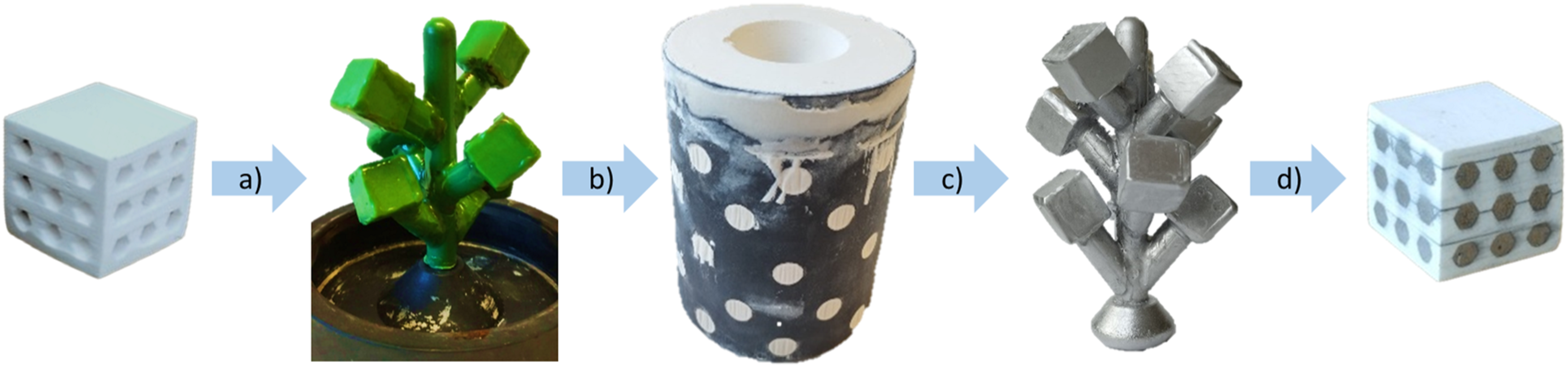
Ceramic and IPCs characterization
Surface and cross-sections scanning electron microscopy (SEM) images of the ceramic structures and IPCs were acquired using a Hitachi S4100 (Japan) equipment, after carbon coating. ImageJ software was used to measure the dimensions of the samples. Micro-computed tomography (µ-CT), a non-destructive technique, was used to obtain a 3D reconstruction and cross sections of the ceramic parts and IPCs. This analysis was performed on Brunker Skyscan X-ray microtomography equipment, where several x-ray projections are recorded and aligned to obtain the virtual model.
To study the thermal behavior of the alumina-loaded resin, Thermogravimetry (TG) analysis was performed, using NEXTA STA300 equipment, from room temperature to 1300°C, using a heating rate of 10°C/min. X-ray diffraction analysis was performed for phase identification, on a Panalytical X’Pert PRO3 equipment, using steps of 0.026° on a 2θ range from 20° to 90°. The bulk density of all sintered ceramic structures was measured by Archimedes immersion method according to ASTM C20-00. 28
Compression tests were performed according to the printing direction both on the ceramic and IPC, using a universal testing machine, model AG-25 TA (Shimadzu, Japan), using a 0.2 mm/min crosshead speed. The resulting mechanical properties are averages obtained from a minimum of five compression tests per group. The energy absorption was determined by the area under the stress-strain curve until a defined strain (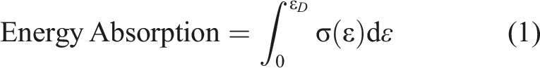
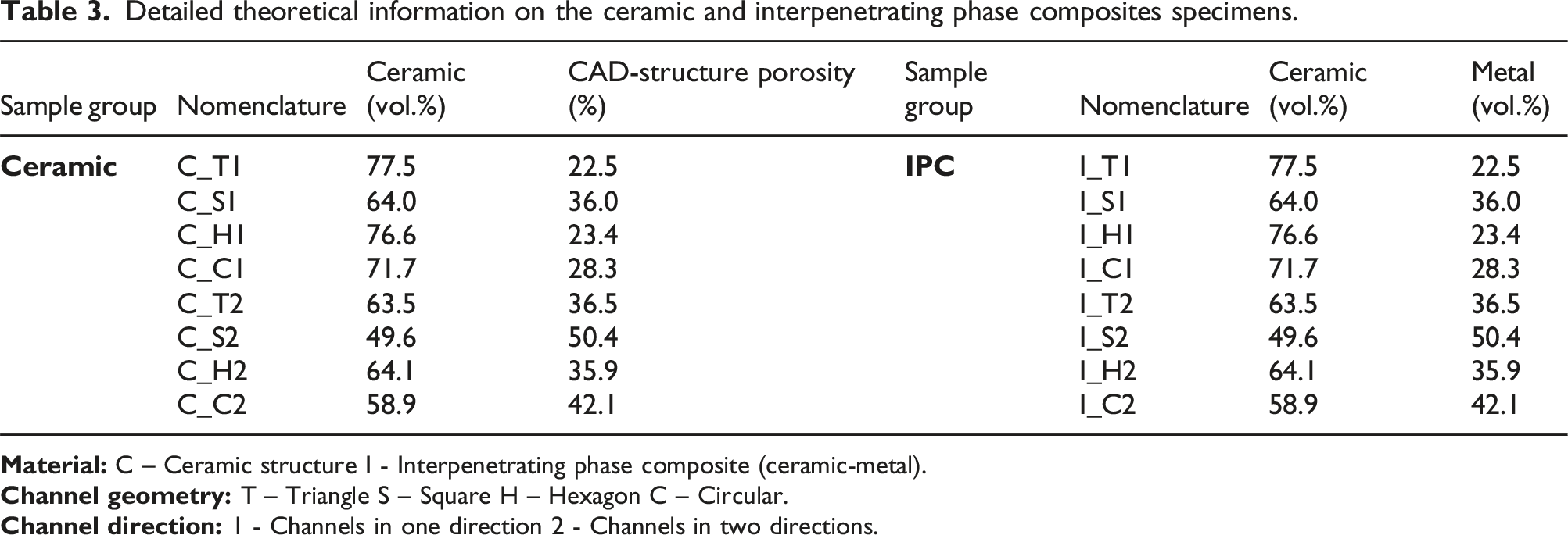
Detailed theoretical information on the ceramic and interpenetrating phase composites specimens.
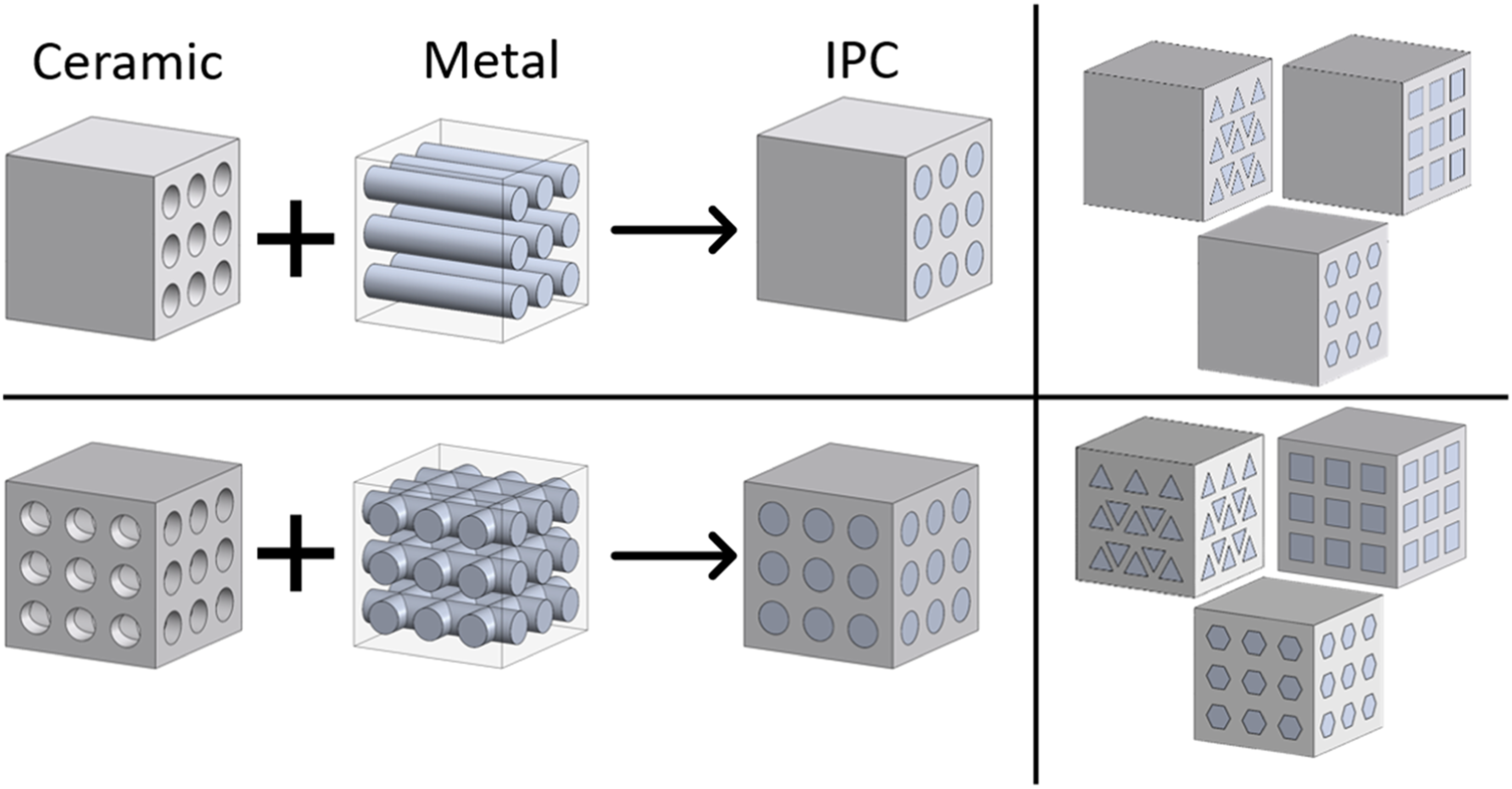
IPCs analyzed and ceramic-metal phase distinctions.
Results and discussion
Morphology and properties
Ceramic structures
Figure 3 shows detailed views of the fabricated ceramic structures, before and after sintering. Globally, it is possible to verify an effective CAD geometry replication, although with the inherent limitations of the technology, e.g., the layer effect. Furthermore, due to the high viscosity of the alumina resin, during the photopolymerization, some resin remains inside the cavities, being polymerized by the backscattered radiation. This problem is especially observable on triangular and hexagonal structures. SEM images with detail views for triangular a) green and b) sintered condition; square c) green and d) sintered; hexagonal e) green and f) sintered; circular g) green and h) sintered.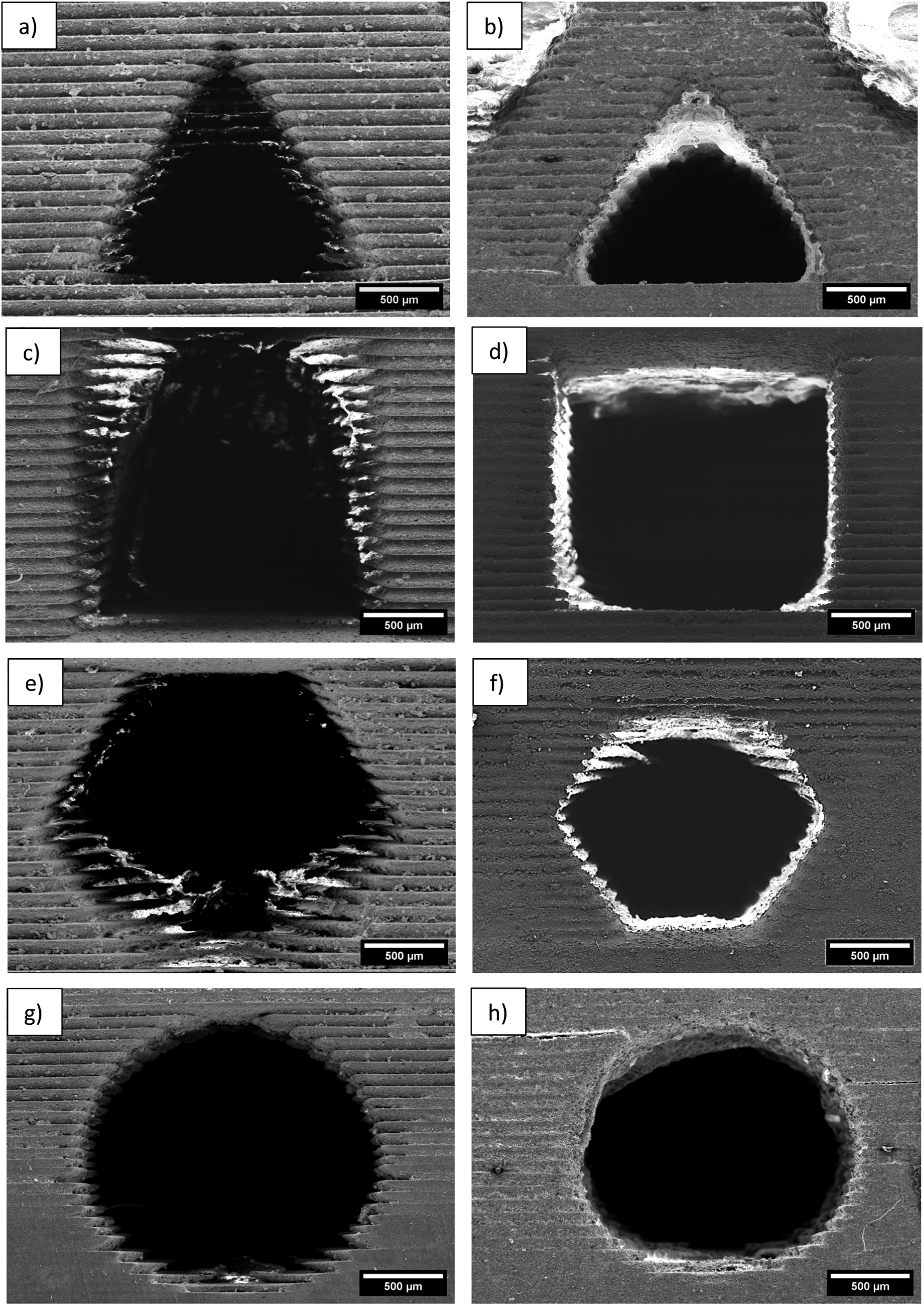
When analyzing the green ceramic parts, obtained after DLP printing, it is possible to verify the typical layer-by-layer effect, corresponding in this case to a layer thickness of 100 µm. After sintering this effect is less pronounced, as seen in Figure 3.
Computer aided design model channel dimensions and resulting dimensions on the green and sintered parts.
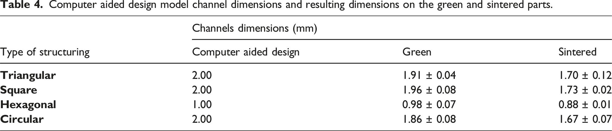
Table 4 depicts the channel dimensions for the different architectures, measured by SEM analysis with the use of ImageJ software. Regarding the CAD model and the printed parts (green condition), a deviation was identified, although it was within the accuracy of the DLP equipment (±0.25 mm). After sintering, for the ceramic structures, an average linear shrinkage of 10.6 % (±1.8) and a volume shrinkage of 28.5 % (±2.4) was verified. Compared to the linear shrinkage values reported in the literature, the results obtained fall within the expected range for vat photopolymerization technologies.26–33 These studies demonstrate that factors such as sintering temperature, debinding cycle, particle morphology, and size distribution, as well as solids content, significantly influence the final results.
Through µ-CT analysis it was possible to verify that the fabrication of the ceramic components by DLP is overall efficient, proving the effectiveness of this technology to replicate CAD geometries and dimensions. Another conclusion taken from µ-CT analysis is that components with channels in two directions have a better definition than structures with unidirectional channels, as seen in Figure 4 for hexagonal-type structures. This outcome is explained by the higher interconnectivity of bi-directional channel architecture, that promotes an easier escape of the non-polymerized alumina resin from the structures during the printing process. µ-CT analysis of C_H1 and C_H2 ceramic components.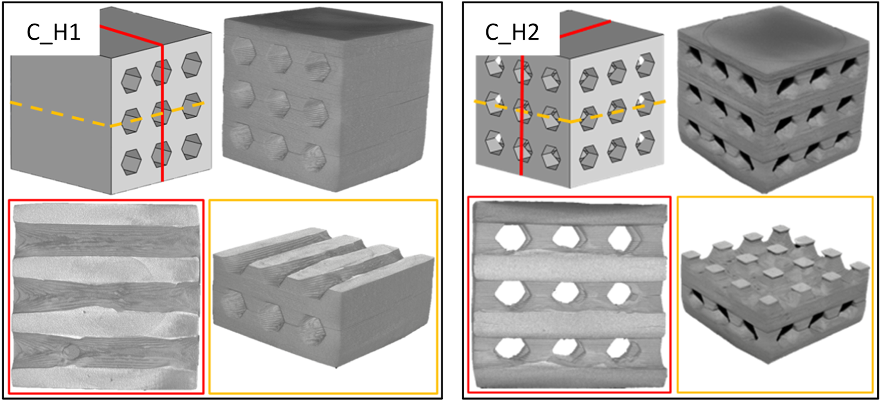
The microstructure of the ceramic structures, on both green and sintered conditions, was analyzed by SEM, as shown in Figure 5. Before sintering, the polymerized resin covering the ceramic particles is easily detected (Figure 5(a)), while after sintering only the alumina particles are visible (Figure 5(b)), due to the complete removal of the organic phase. Ceramic part microstructure in a) green and b) sintered conditions.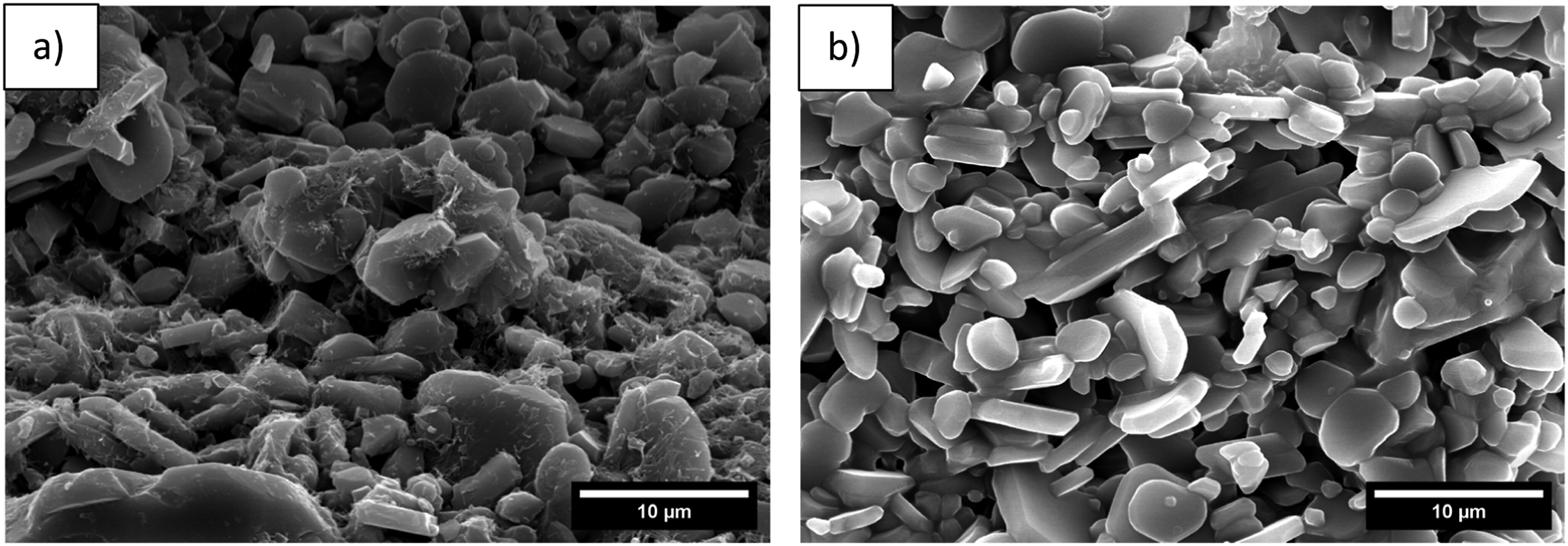
When analyzing Figure 5(b), it is possible to verify the existence of voids between the alumina particles, that will dictate the alumina porosity. The relative density of the alumina was determined, being 67.4 % (±3.5), corresponding to a ceramic porosity of 32.6 %. The low densification attained could be related to several factors including particle size and size distribution, particle shape, particle packing, and sintering cycle. The literature has mentioned the difficulties in attaining high densification values from photopolymerization technologies. 34 Li et al. 35 reported the relation between the sintering temperature and the resulting porosity/density of DLP-printed alumina cores for hollow turbine blades. These authors concluded that for a temperature of 1400°C a high ceramic porosity (∼35%) was observed while for higher temperatures (1550°C), this value reduced to 16.9 %. Moreover, Wu et al., 36 concluded that the resulting relative density is correlated to the particle sizes of raw materials and their distribution, being observed that micrometric alumina, sintered at 1750°C display 65.7 % relative density, while a bimodal granulometric distribution resulted in 91.2 % relative density. As the densification mechanisms progress, porosity is reduced followed by shrinkage of the samples. 31 The low relative density of the sintered samples can also explain the relatively low values obtained for the linear shrinkage. Although conventionally fabricated ceramic components present higher densification than DLP parts, this AM technology brings the advantage of allowing the manufacture of complex geometries and architectures that are unattainable by conventional ceramic fabrication technologies. 37
Figure 6(a) shows the TG analysis performed on the alumina-loaded resin, showing that the full burn out of the organic component of the resin is completed at a temperature of approximately 700°C representing 28.73 %. X-ray diffraction analysis performed on the sintered alumina (Figure 6(b)) demonstrates exclusively the presence of α-Al2O3 (Figure 6(b)). a) TG analysis of the alumina loaded resin and b) XRD analysis of the sintered ceramic component.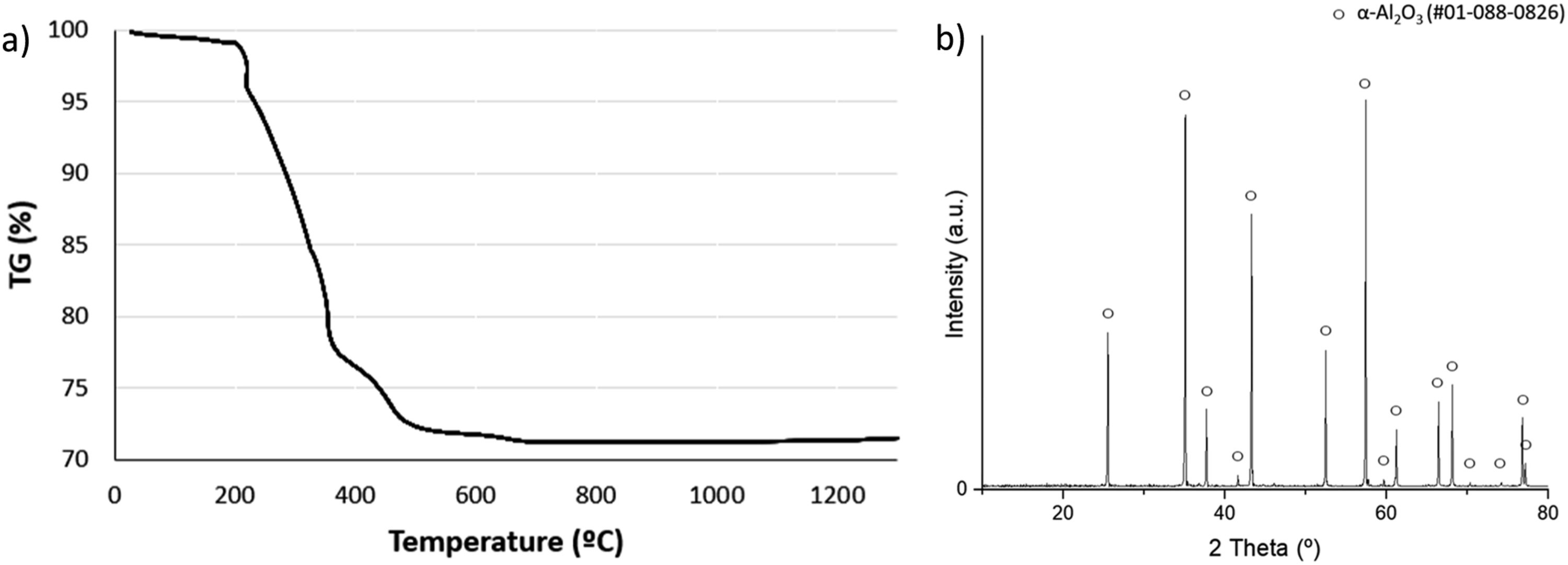
Interpenetrating phase composites
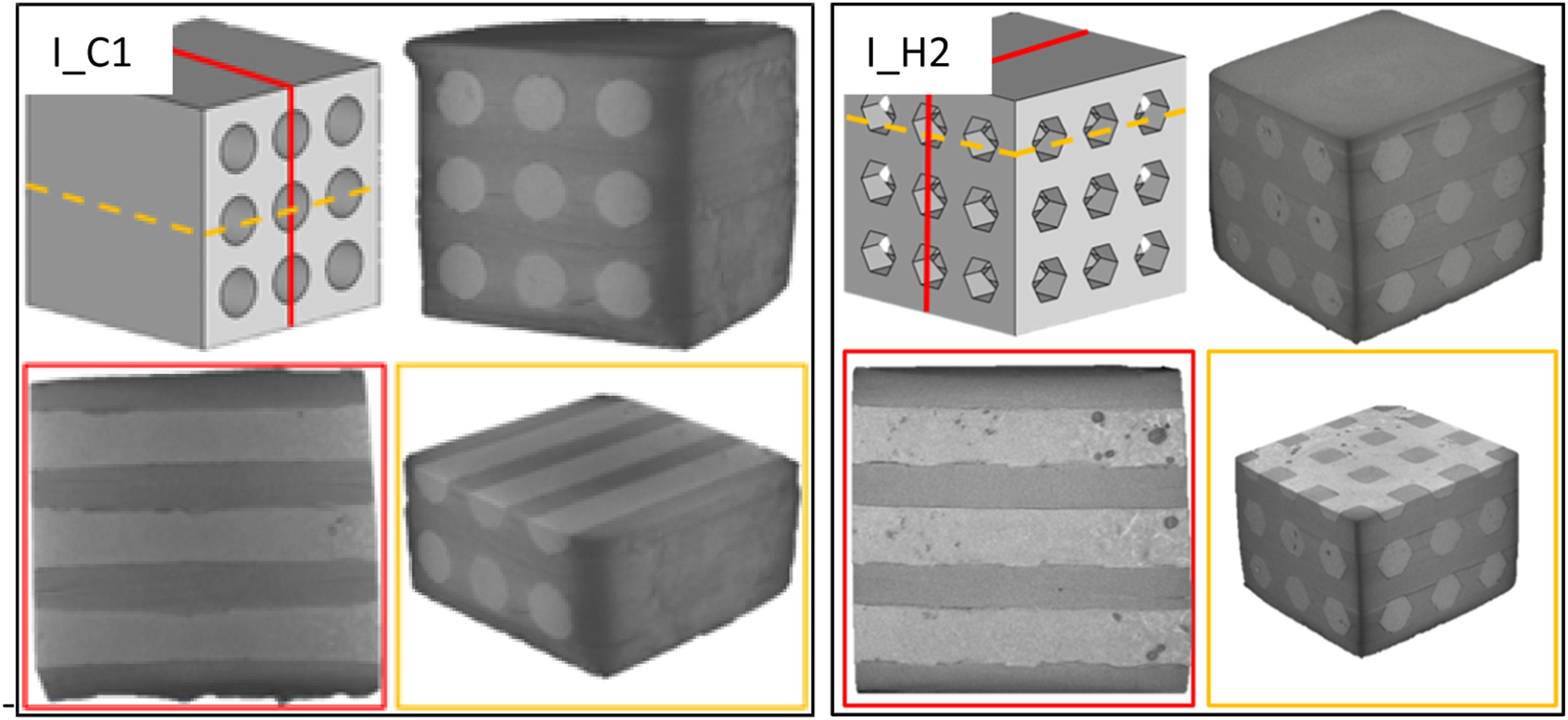
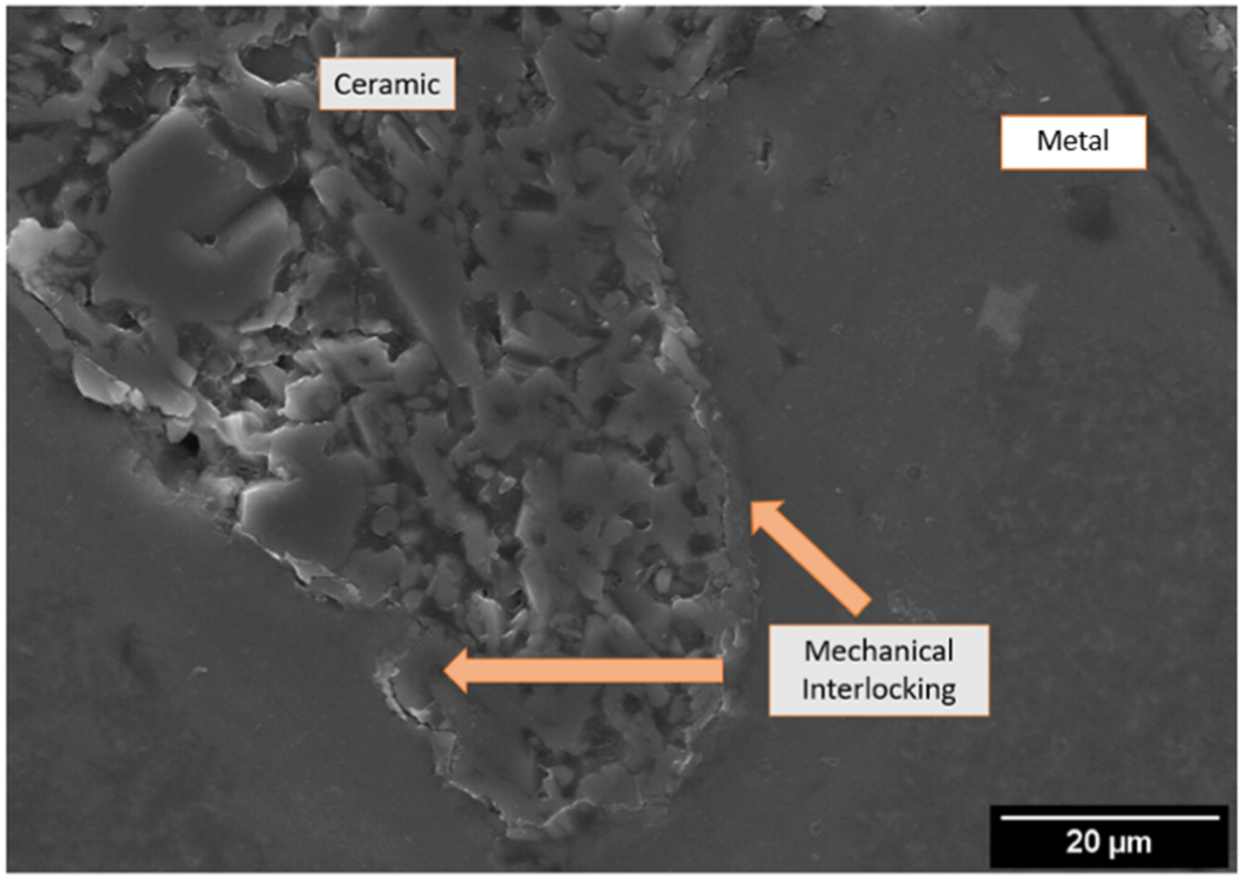
After sintering the ceramic structures, these were infiltrated with the aluminum alloy, and generally it was possible to conclude that despite the different channel geometries, an efficient infill was attained, as proven by cross-section (Figure 7) and µ-CT (Figure 8) analysis, albeit some residual porosity on the aluminum. Figure 7 demonstrated that, independently of the IPC channels geometry, a successful infiltration is achieved, with no visible voids at the interface. Also, in Figure 9, the use of a higher magnification allows to confirm the effectiveness of the infiltration process, assuring a mechanical interlocking at a macro level, as the metal alloy effectively filled the AM layer-by-layer surface topography of the ceramic parts. In addition, µ-CT analysis (Figure 8), also confirmed an effective infiltration of the metallic alloy throughout the ceramic structure. SEM images for the different IPCs: a) triangular; b) square; c) hexagonal; d) circular. µ-CT analysis of I_C1 and I_H2 IPC components. Mechanical interlocking between the ceramic and metallic components.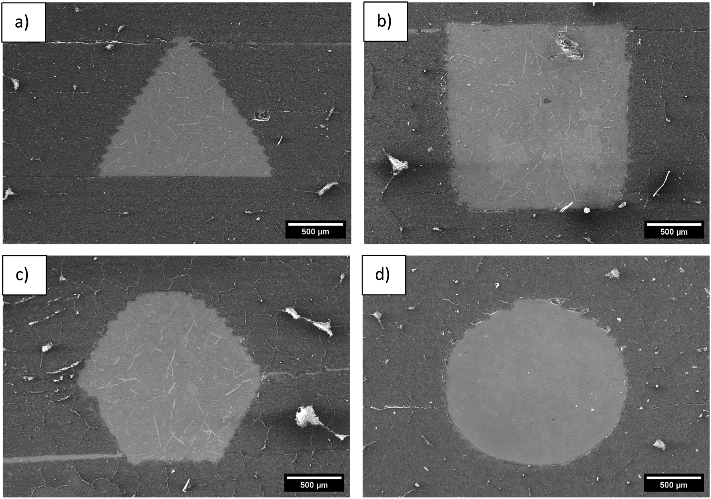
The microstructure of the aluminum alloy infilled in the ceramic structures was analyzed by optical microscopy (Figure 10), displaying, Si particles and α-Al. The Si particles present a fibrous morphology, and it is in the form of needle-shaped plates dispersed through the α-Al matrix, commonly reported in this microstructure.
38
Microstructure of the AlSi12Fe alloy used.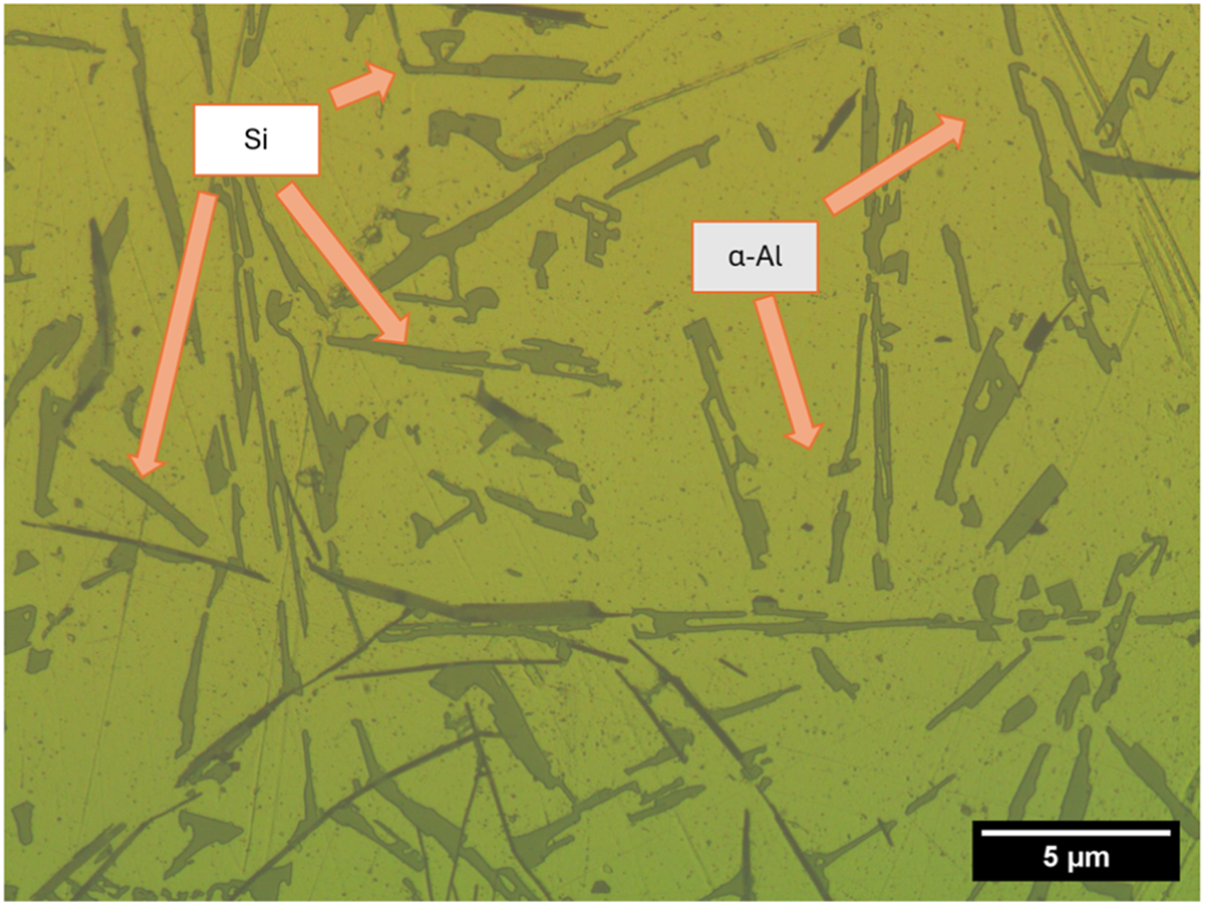
Mechanical characterization
Ceramic structures
Figure 11(a) and (b) display representative stress-strain curves for the ceramic structures. These exhibit a typical ceramic behavior characterized by reaching a peak stress, followed by a stress drop indicative of structural collapse. This type of behavior has been described in other ceramic foams and structures under compression, as evidenced in the research conducted by Acchar et al.
39
Globally, for structures having unidirectional channels, the maximum stress is achieved at a strain between 0.043 and 0.056, while for bidirectional structures, the maximum stress is observed at a lower strain, namely between 0.031 and 0.042. This outcome indicates the higher load-bearing ability of ceramic structures having unidirectional channels, comparatively to bidirectional counterparts. Compressive response of ceramic structures: a) Stress-strain curves for structures with unidirectional channels; b) Stress-strain curves for structures with bidirectional channels; c) Compressive strength; d) Energy absorption.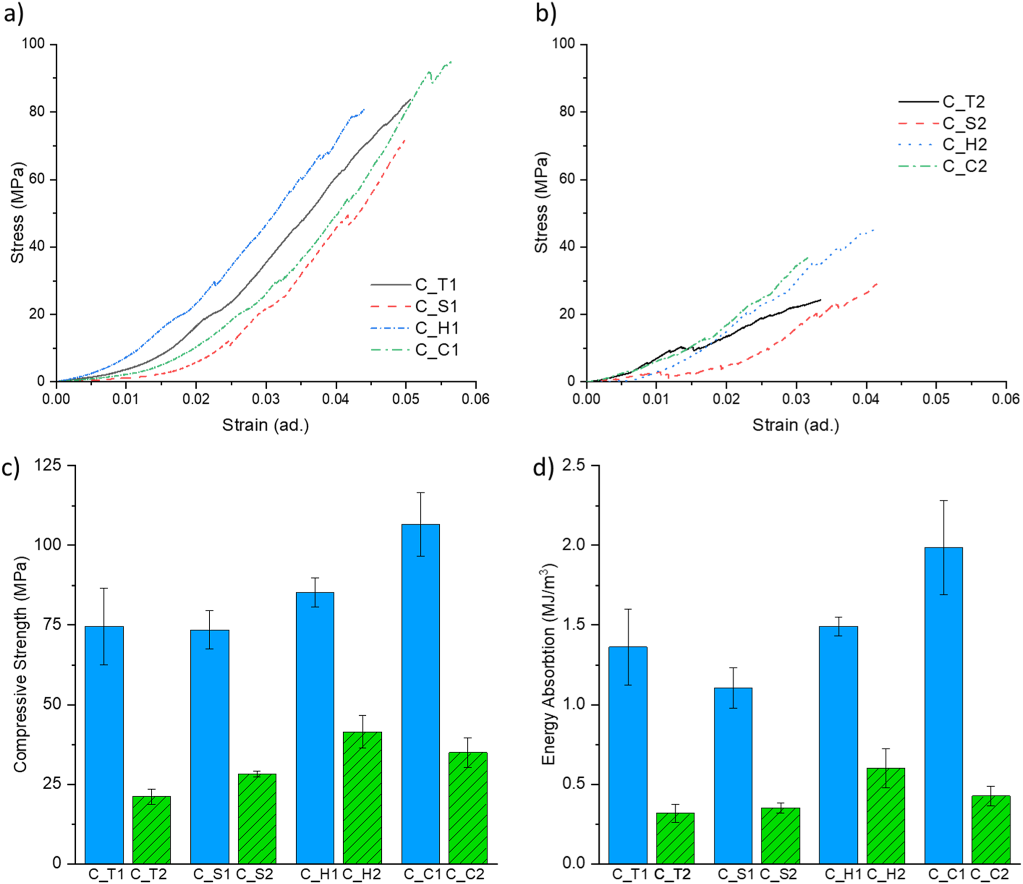
Figure 11(c) and (d) present the compressive strength and absorbed energy, respectively, for the different types of ceramic structures. A compressive strength reduction between 57.3% and 71.6% was observed when comparing structures with bidirectional channels to those with unidirectional channels. This decrease in strength is attributed to the effective load-bearing area on these structures, which is reduced by 40% when having bidirectional channels. This fact leads to an increase in local stress on the structures having bidirectional channels. Consequently, the absorbed energy, represented by the area under the stress-strain curve, follows the same trend found for compressive strength. It was found that the energy absorption was reduced from 64.9% to 80.7% when comparing bidirectional channel structures with the correspondent unidirectional ones.
Regarding the structures with unidirectional channels, C_C1 (circular) exhibited the highest compressive strength and energy absorption. On the other hand, triangular and square channels exhibited the lowest values for compressive strength and absorbed energy, on both unidirectional and bidirectional channels. Due to their brittle nature, ceramics are highly sensitive to stress concentration points. Different structures geometries can lead to very distinctive stress distributions and on ceramic materials these differences can lead to very different performances. 40 On a macro-geometry analysis, circular channels, by lacking on-plane vertices, can lower the stress concentration. In contrast, other tested geometries having on-plane vertices are more prone to induce such stress concentrations. However, other aspects like backscattered polymerization, local printing defects, and the typical layer effect also contribute to the final performance.
Interpenetrating phase composites
Figure 12(a) and (b) present representative stress-strain curves for the IPCs. The typical brittle behavior observed in the ceramic structures is significantly altered with the introduction of aluminum alloy, as the structure porosity is now infiltrated by a ductile material. In the case of the IPCs having unidirectional aluminum filling, instead of a sharp stress drop corresponding to the collapse of the structure, seen in ceramic structures, these IPCs display a gradual stress decay following the maximum stress. Conversely, IPCs having bidirectional aluminum filling demonstrated a typical ductile behavior similar to that of metal structures, featuring an identifiable plateau stress across all tested groups. This dissimilar behavior is related to the distinct confinement of the aluminum struts within the IPC. In structures with unidirectional channels, the ceramic phase surrounds the metal phase, leading to a quasi-independent phase behavior. In this scenario, the ceramic material fractures first, and then the metal struts act as obstacles to further deformation, causing a gradual decay in load-bearing capacity. This is evident in Figure 13, which shows this response after the ceramic breaking point. Conversely, in structures having bidirectional channels, the metal phase encloses the ceramic phase, resulting in a dependent phase behavior. Here, the fractured ceramic phase is trapped within the aluminum, creating a plateau region followed by a densification region. This behavior is clearly visible in Figure 15, where, after the ceramic breaking point, the metallic structure maintains the integrity of the IPC and withstands additional load. Compressive response of IPCs: a) Stress-strain curves for IPCs with unidirectional aluminum filling; b) Stress-strain curves for IPCs with bidirectional aluminum filling; c) Compressive strength of IPCs; d) Energy absorption capacity of IPCs. Representative stress-strain curve of I_H1 IPC.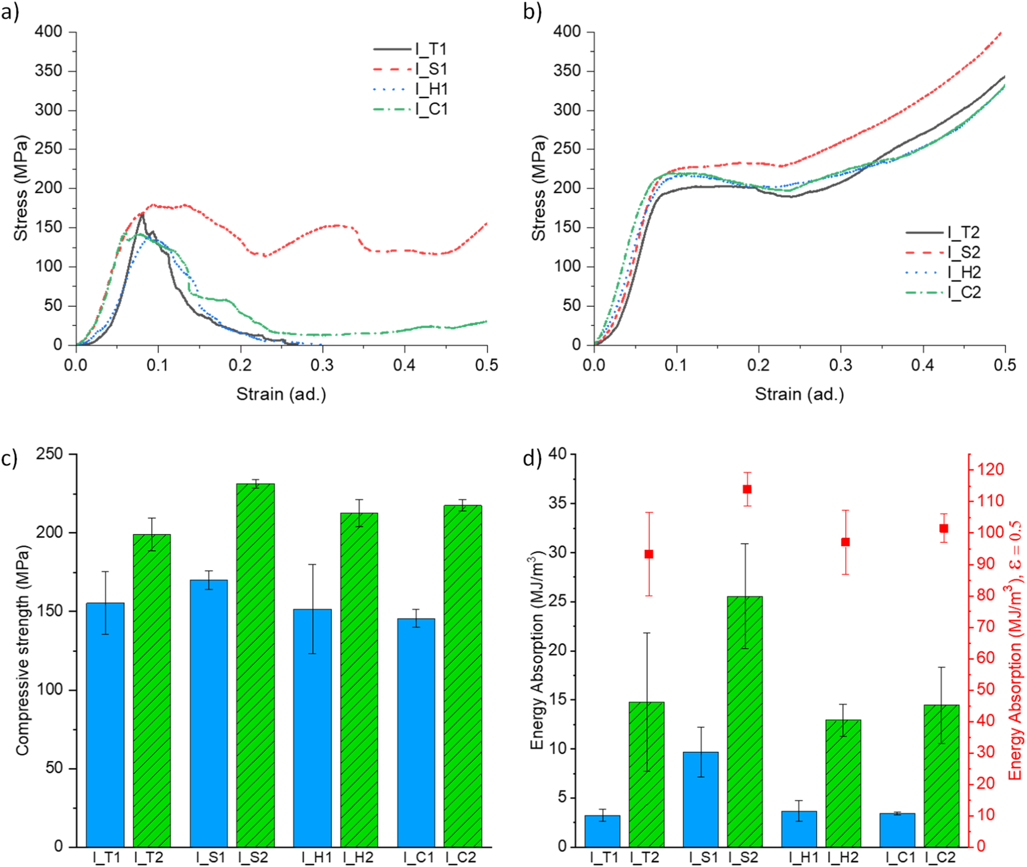
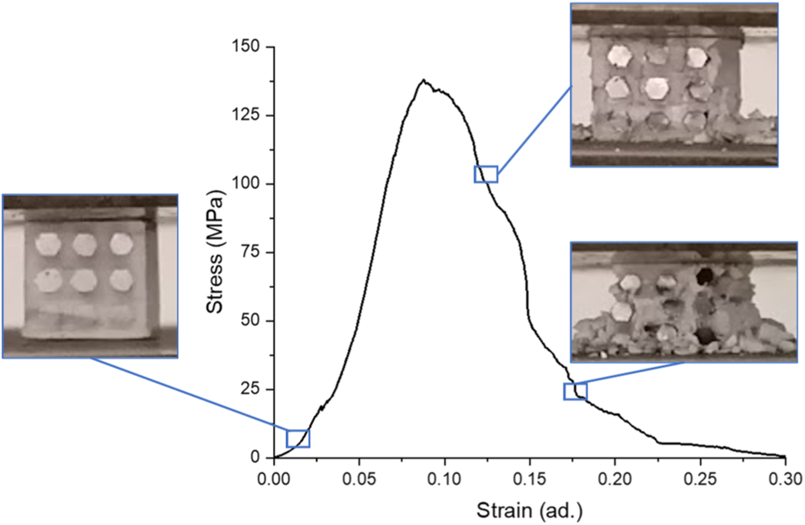
Figure 12(c) presents the compressive strength of the different IPCs in this study. The presence of a higher metal-to-ceramic volume ratio led to expressively higher compressive strength when compared with unidirectional IPCs. When comparing bidirectional IPCs with unidirectional IPCs, having the same type of structuring, higher compressive strength, from 36.2 % to 42.3 % were observed, with the highest increase being found for the circular-type.
Figure 12(d) presents the energy absorption obtained for the different IPCs in the study. As for the absorbed energy till the first maximum stress, an expressive increase was found by introducing the aluminum alloy in two directions, with a 164.8% to 358.1% enhancement when compared with the corresponding unidirectional parts. Additionally, the energy absorption till 0.5 strain was determined according to ISO 13314:2011 41 for the structures that exhibited a well-defined plateau region: I_T2, I_S2, I_H2, and I_C2. Compared to the values attained until the first maximum stress, expressively higher values are obtained, due to the densification phenomenon previously described and perceived in the plateau region of the stress-strain curves, showing these parts potential for energy absorption applications. The obtained results are coherent with the metal-to-ceramic volume ratio, which is maximum in the square-type IPCs.
Among the IPCs having unidirectional aluminum filling, a distinctive behavior was consistently observed for I_S1, as seen in Figure 14, where images of the specimen along the test were added. When comparing I_ H1 (Figure 13) with I_S1 (Figure 14), it is possible to perceive a higher load-bearing ability of the latter, due to a significantly higher content of aluminum on the part, namely 36.0 % for I_S1 versus 23.4% for I_H1. Regarding the I_H1 sample, it’s possible to verify a somewhat fragile behavior, comparable to the ceramic samples, but with added load-bearing capacity due to the addition of the metallic component. While the sample I_S1 presents a higher volume percentage of aluminum, making it able to uphold a higher load. Another aspect that makes the I_S1 sample interesting is its behavior during uniaxial compression, not exclusively ductile nor fragile, but a mixture of both. During the compression it’s possible to verify an initial stage where both components (ceramic and metal) are upholding the load applied, till a certain maximum stress where the ceramic starts to break and crumble until the overall component compresses and the metallic component starts to hold the load (represented with an increase of stress after a considerable decay), the stress will continue to increase until another segment of the ceramic component breaks, decreasing the load. This process is repeated till the end of the test. Representative stress-strain curve of I_S1 IPC.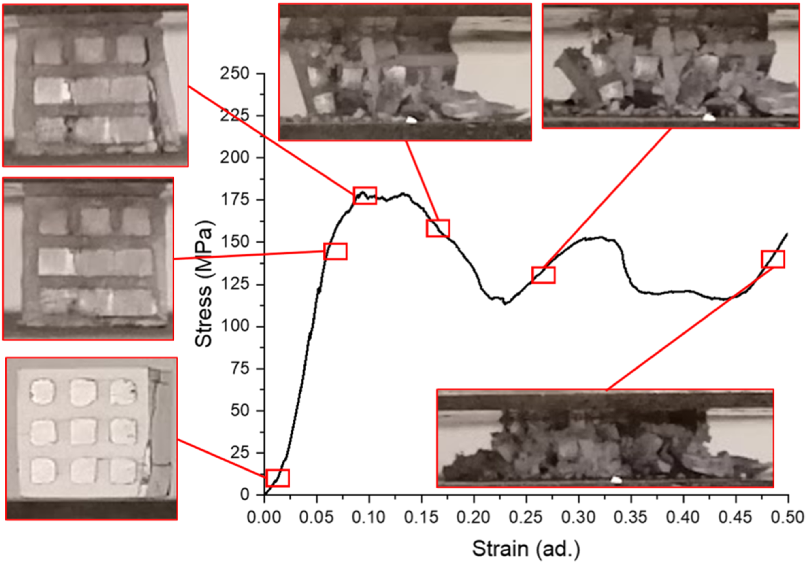
When analyzing parts having bidirectional aluminum filling, a consistent change on the stress-strain curve was observed for all the tested IPCs showing a typical metallic structure behavior. Taking as an example I_H2 IPC (Figure 15), it is possible to observe that after the linear elastic deformation, a plateau region is observed, followed by densification stage, as described in ISO 13314:2011.
41
This densification significantly impacts the energy absorption capacity of these materials, as shown by analyzing the results depicted in Figure 12(b) regarding the absorbed energy of these IPCs. Representative stress-strain curve of I_H2 IPC.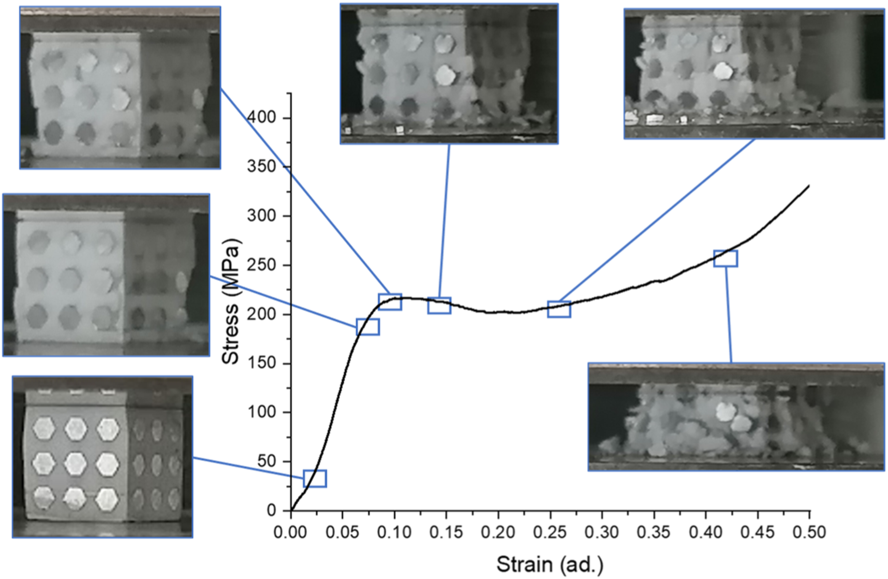
Conclusions
In this study, aluminum-alumina IPCs were effectively fabricated through the combination of additive manufacturing technology, namely Digital Light Processing, for the alumina porous structure fabrication, with investment casting for the infiltration of aluminum on these structures.
Ceramic structures with triangular, square, hexagonal, and circular channels were manufactured by DLP, having channels in one (unidirectional) or two directions (bidirectional), having CAD structure porosity between 22.5 % and 36.5 % for unidirectional structures and between 35.9 % and 50.4 % for bidirectional structures. The ceramic structures compressive strength and absorbed energy are significantly diminished by adding channels in two directions, in respect to the corresponding unidirectional structures.
The addition of the aluminum alloy into the CAD structure porosity of the ceramic structures altered the typical ceramic fragile behavior under compression to a ductile behavior, especially in the bidirectional IPCs. The compressive strength and absorbed energy of the IPCs were expressively higher than the ceramic counterparts that were used for their fabrication. When comparing IPCs having bidirectional with unidirectional aluminum infill, a significant increase in compressive strength and absorbed energy was observed, from 36.2% to 42.3% and from 164.8% to 358.1%, respectively.
Footnotes
Declaration of conflicting interests
The author(s) declared no potential conflicts of interest with respect to the research, authorship, and/or publication of this article.
Funding
The author(s) disclosed receipt of the following financial support for the research, authorship, and/or publication of this article: This work was developed within the scope of the project CICECO-Aveiro Institute of Materials, UIDB/50011/2020, UIDP/50011/2020 & LA/P/0006/2020, financed by national funds through the FCT/MCTES (PIDDAC) - Fundação para a Ciência e a Tecnologia (FCT). S. M. Olhero acknowledges FCT through CEECIND/03393/2017 contract. The authors also acknowledge the support by the projects UIDB/00481/2020 and UIDP/00481/2020 - Fundação para a Ciência e a Tecnologia; and CENTRO-01-0145-FEDER-022083 - Centro Portugal Regional Operational Programme (Centro 2020), under the PORTUGAL 2020 Partnership Agreement, through the European Regional Development Fund.
Data availability statement
Data will be made available upon request.