
Abstract
This paper presents an investigation into prepreg tape composition and its impact on the consolidation quality of in‐situ Automated Fiber Placement-manufactured laminates. Three different prepreg tape materials were investigated in terms of fiber distribution, porosity and surface roughness. Laminates were manufactured using the in-situ Automated Fiber Placement process and subsequently tested using microanalysis and mechanical testing methods. Higher quality prepreg tape material yielded lower porosity laminates and increased mechanical strength results. The best in-situ Automated Fiber Placement-manufactured laminates achieved 82 % and 88 % of hot-pressed reference tensile- and compressive strength, respectively. Prepreg tape with disadvantageous composition for in‐situ consolidation yielded up to 74 % knockdown compared to the best in-situ consolidated laminates. A five-point bending test was successfully used to determine interlaminar shear strength with significant results relating to consolidation quality. A correlation was successfully established between prepreg composition, resulting laminate consolidation quality and mechanical properties.
Introduction
Thermoplastic Automated Fiber Placement (AFP) has great potential to reduce manufacturing time and cost by means of in‐situ consolidation omitting subsequent consolidation processes such as press- or autoclave consolidation. There is however an ongoing debate as to whether in‐situ consolidation can achieve sufficient laminate quality for aerospace applications.
Important work in the field: Press versus in‐situ
Numerous studies have investigated the comparison of in‐situ AFP and press- or autoclave reference. Groundbreaking work by Lamontia et al. found decreased compressive- and interlaminar shear strength for in‐situ AFP-manufactured AS4/PEEK and PEKK cylinders compared to autoclaved reference 1 . Voids, layer waviness and decreased crystallinity resulted in decreased mechanical properties. Comer et al. found increased wedge peel strength (134 %) but decreased flexural strength (68 %), flexural stiffness (88 %), short beam strength (70 %) and open hole compressive strength (78 %) as compared to autoclave reference 2 . The same group (Ray et al. 2015 3 ) found 60-80 % higher CF/PEEK fracture toughness for in-situ AFP compared to autoclave but lower overall stiffness and strength.
For this present work carbon-fiber-reinforced low-melt polyaryl ether ketone (CF/LM-PAEK) prepreg material was used. This novel material promises similar mechanical properties as PEEK-based composites combined with lower melt-temperature (307°C, PEEK: 343°C) and lower melt viscosity, facilitating AFP processing and enabling higher layup rates.4,5 CF/LM-PAEK prepreg tape is available from different manufacturers and with varying compositions. TC1225 by Toray Advanced Composites was used in previous publications and Part 1 of this work.5–7 For this material, Seneviratne et al. found a short beam strength of 42 % (33.5 MPa) of press-consolidated reference, low crystallinity values at 4.1 to 5.1 % and high porosity of 3.9 % to 5.8 %. Signifigant strength knockdown factors compared to press-consolidated reference were found in Part 1 of this work for unheated tooling, as well.
Heated tooling
A heated tooling was found to increase mechanical properties of in-situ AFP-manufactured laminates. Seneviratne et al. used a heated tooling configuration and achieved short beam strength of 41.5 MPa compared to 33.5 MPa with unheated tooling. 8 Tehrani et al. investigated in-situ AFP using Suprem CF/LM-PAEK prepreg material and a 100°C heated tooling, achieving porosity as low as 0.5 %, short beam bending strength of 62 MPa and 20 % crystallinity. The good results were at least in part due to the higher quality 55 % fiber volume fraction material. 9 In Part 1 of this work, a heated tooling at 200°C and unidirectional layup resulted in an improved short beam strength of 57 MPa compared to 46 MPa with unheated tooling configuration. The heated tooling configuration resulted in a crystallinity of 25 %, which was close to press-consolidated reference of 27 %. 4 Even with a heated tooling configuration, there is in many cases still a strength knockdown between in-situ AFP and reference laminates. To explain these knockdown effects two main influencing factors can be gleaned from the literature.
In-situ AFP process window
On the one hand, the knockdown of the mechanical properties can be explained by the dynamic nature of the process, high cooling rates and short consolidation time. A process principle diagram is shown in Figure 1. As discussed in Part 1 of this work, in-situ AFP uses a heat source, often a laser, to heat the substrate and incoming tape material. A consolidation roller is then used, to press the tape onto the substrate and fully consolidate the two joining partners in an additive process. The point of first contact of tape and substrate is called nip point and is followed by an area of applied pressure, due to the compliance of the silicone roller. The laser light couples into the carbon fibers at the tape- and substrate surface. Due to the short heating time, only the prepreg surface is heated. Full through-thickness heating does not occur, resulting in lower overall crystallinity, and specifically lower crystallinity in the center of the layers, which remain largely unchanged by the laser AFP process.2,3 This varying crystallinity distribution over the laminate cross-section with amorphous portions in the ply centers might in part explain increased toughness and decreased strength results. Because of the geometry-related laser shadow right in front of the nip-point, significant overheating is required, to achieve the optimal nip-point temperature.10–12 At the same time, however, the process temperature must remain below the decomposition temperature of the matrix polymer. The in-situ AFP process window is thus very narrow and the process is very sensitive to its process parameters. In-situ AFP process principle diagram.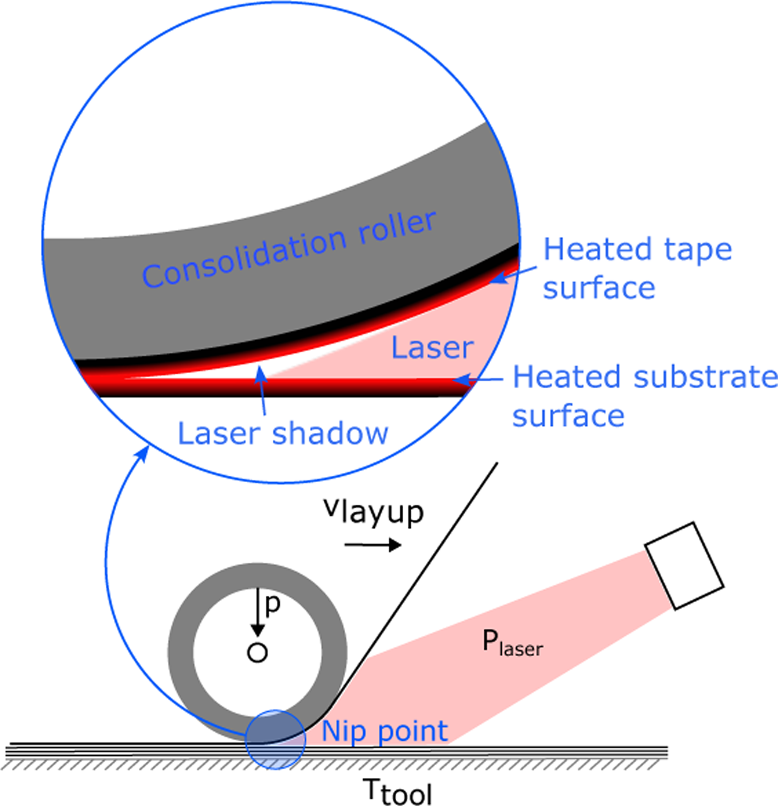
Intimate contact
The second main factor for the consolidation quality is the prepreg tape composition. Only the combination of an optimal process window and high quality prepreg tape, that is well-suited for AFP, can achieve high quality in-situ consolidated laminates. 12 The prepreg tape composition determines the degree of intimate contact, which is a key metric for consolidation. Only areas of the interface that make intimate contact can subsequently be joined by healing and polymer chain interdiffusion. Khan et al. investigated the impact of various parameters including prepreg tape quality on in-situ AFP using a hot torch heat source. Smooth prepreg tape surface was shown to generate better intimate contact, higher degree of bonding and thus higher strength laminates. 13 Further research found that high quality tape with low initial void content results in higher quality laminates since it is less prone to void deconsolidation. Furthermore, tape with lower surface roughness yielded better intimate contact build-up and resulted in enhanced bonding. 14 Celik and Teuwen investigated intimate contact for laser in-situ AFP and found a linear relationship between consolidation pressure and 3effective intimated contact, and a non-linear decrease in effective intimate contact with increasing layup speed. Effective intimate contact considers only resin contact areas, omitting areas of dry fiber contact as consolidation can only take place with resin present.15,16 Similarly, Grimsley et al. and Tierney et al. found surface roughness and presence of sufficient polymer at the surface likely to affect intimate contact, fusion-bonding and healing.17,18
Previous work by this group has focused primarily on the first main influencing factor - the in-situ AFP process window, as introduced in the previous subsection. Manufacturing equipment-specific processing parameters were optimized in comprehensive Design of Experiment studies and taken up for the following investigation.6,7 The results were extended in an investigation of layup speed sensitivity of TC1225 and a second CF/LM-PAEK material with 55 % fiber volume fraction. 5 Part 1 of this work investigated in-situ consolidation of 60 % fiber volume fraction (FVF) prepreg tape material, optimized for established production technologies (autoclave and hot press). Heated tooling and post process tempering were investigated with regards to their impact on mechanical and thermal properties.
Novelty
Part 2 of this work focuses on the second main influencing factor - intimate contact and prepreg tape composition. While tape composition was identified as a critical factor for in-situ AFP consolidation quality in the literature, a comparison of different prepreg tape compositions and analysis of resulting laminate quality has not yet been done. This work aims to clarify the impact of prepreg tape composition on the resulting in-situ AFP laminates by providing a coherent dataset of three different materials, all processed and tested using the same equipment. It elaborates and builds upon the research group’s previous work and, for the time being, marks the conclusion of research on process optimization and laminate characterization for CF/LM-PAEK materials. For this work, three prepreg tape materials were processed and correlated with the resulting laminate quality. To this end a methodology for the quantification of fiber volume fraction distribution, surface roughness and porosity of prepreg tape as well as consolidated laminates by means of ultrasonic scanning, microsectioning and micro computed tomography scans was developed and is presented in this work.
Materials and methods
CF/LM-PAEK prepreg materials.
Surface roughness
The surface roughness of tapes was estimated using a Keyence VR-5200 3D optical measurement system. From each tape, a sample of 10 cm in length was taken. Multiple line roughness was measured at three positions of the sample. The lower and upper threshold wavelength of the filter was set to λ s = 25 µm and λ c = 0.8 mm.
Microanalysis
The porosity of both, unprocessed prepreg tape materials and manufactured laminates was determined via micrographs of polished specimens. Ten micrographs were prepared for each of the three investigated prepreg tapes. Micrographs were recorded at 500x magnification using a Keyence VHX-5000 digital microscope with a VH-ZST dual-objective zoom lens. The images were processed using the open source software ImageJ. Because of the small thickness of around 0.2 mm, accurate positioning of the image section is vital for the area fraction measurement, as to only include the inner porosity. Uneven or crooked surfaces would otherwise lead to compromised results by the segmented mounting material. The quality of the consolidation and therefore interlaminar porosity depends to some degree on the amount of matrix on the surfaces. As a result, high quality tapes are expected to show a lower fiber volume content at the surfaces compared to the center. In order to evaluate this property, a MATLAB script was used to determine the fiber volume content distribution as a function of thickness. The method is based on cross section micrographs. The script requires two manually prepared binary images of the same section. 10 microsections were prepared and analyzed for each investigated prepreg tape material.
Automated fiber placement
Laminates were manufactured at the tape placement facility at DLR Institute of Structures and Design in Stuttgart, Germany (Figure 2). Thermoplastic tape placement facility at DLR Institute of Structures and Design, Stuttgart.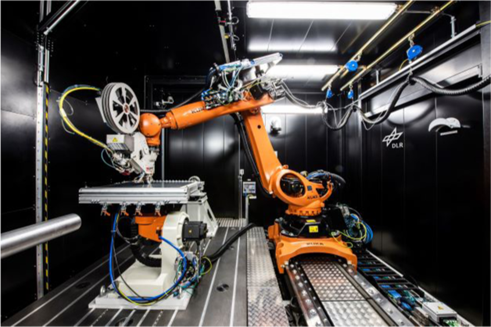
The facility comprises a 6-degree-of-freedom robot, a 6 kW near-infrared laser and an AFPT Multi Tape Laying Head. A closed loop temperature control system enables precise adherence to the target nip-point temperature. For all three materials, three half inch (12.7 mm) tapes were layed up simultaneously. All laminates were manufactured on a 200°C heated tooling, using a layup speed of 125 mm/s. The nip-point temperature was set to 470°C using the thermocamera of the temperature control system and an emissivity coefficient of ϵ = 1. The pneumatic system consolidation pressure was set to 6 bar. These parameters were determined for CF/LM-PAEK single lap shear specimens in a comprehensive parameter study.6,7 and were also used for quasiisotropic laminates in Part 1 of this work. A 60 mm-wide cooled consolidation roller with a 5 mm-thick shore A 60 silicone sheath was used to apply the consolidation pressure. For each of the three materials a 16 ply quasiisotropic laminate was manufactured. The ply stacking sequence was [0/45/90/-45]2S. A second laminate was manufactured using Tape 1, which was subsequently re-consolidated in a standard hot-press process and is used as are reference for the in-situ AFP values.
Ultrasonic testing
Ultrasonic scans were performed with an Olympus OmniScan MX2 with a 5L64-NW1 phased array probe. A frequency of 5 MHz was selected because of its common use, providing comparability of the results with the literature.
Differential scanning calorimetry
The degree of crystallinity was measured using a NETZSCH DSC 214 Polyma Differential Scanning Calorimetry (DSC) device. Aluminium crucibles with pierced lids containing the samples, combined with an empty crucible and nitrogen as a protective gas were used for the measurements. Specimens were extracted from the laminates using water jet cut and handsawing. The degree of crystallinity X
c
was determined following equation (1).
19
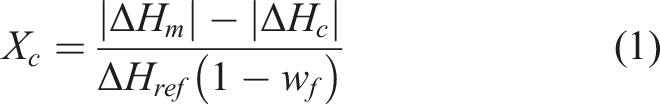
NETZSCH Proteus® Software was used to determine the heat flow difference values between sample and reference ΔH m and ΔH c . For the CF/LM-PAEK materials, the crystallization enthalpy H ref = 130 J/g and the respective mass fractions w f of 62 % and 66 % were used. Linear baseline and evaluation limits of 225°C to 330°C were chosen for the area calculation.
Computed tomography
Micro computed tomography (μCT) scans were prepared using a high resolution nanotom inspection system (GE Sensing & Inspection Technologies GmbH, Wunstorf). X-ray parameters 80 kV/180 μA, an exposure time of 500 ms and 1400 projections per sample were used to achieve a voxcel size of 3 μm. Data analysis and visualisation was conducted using the commercial software package VGStudioMax 3.4 (Volume Graphics GmbH, Heidelberg).
Mechanical characterisation
Tensile and compressive tests were prepared and tested in the same manner as in Part 1 of this work. Specimens were plasma activated and fit with 1.5 mm glass fibre-reinforced epoxy end tabs. A specimen saw was used for final cutting. Tensile test were carried out following AITM 1-0007 A2 test standard.
20
Specimen dimensions were 250 mm by 22 mm with 50 mm end tabs. The samples were tested until final failure at a rate of 2 mm/min using a ZwickRoell 500 kN material testing machine. Ultimate tensile stress was calculated following

where P u is the maximum load, t n is the thickness of the specimen and w is the specimen width. Tensile modulus was calculated following
Similarly, compressive tests were carried out following AITM 1-0008 A2 test standard.
21
Specimen dimensions were 172 mm by 22 mm with 75 mm end tabs. The samples were tested until final failure at a rate of 0.5 mm/min using a ZwickRoell 200 kN material testing machine. Ultimate compressive stress was calculated following
Interlaminar shear strength (ILSS) was determined in Part 1 using a standard three-point bending test (EN 2563 test standard). Due to the ductility of the thermoplastic specimens and non-standard failure mode, an evaluation methodology using crossing tangents was used. Consequently, the resulting strength values were significantly lower than the strength values at specimen ultimate failure. Similar issues were reported for thermoplastic composites in.22–24 A five-point-bending test is used in Part 2, addressing the shortcomings of the three-point-bending tests for interlaminar shear strength measurements of thermoplastic specimens. Using the five-point-bending test, also referred to as double beam shear test, two regions of pure interlaminar shear stress between the center support point and the two load application points are obtained. The test has been shown to consistently lead to delamination failure at one of the two sections of pure interlaminar shear stress. 25
The five-point bending test follows test standard DIN ISO-19927
26
with a span-to-thickness ratio l/t of 5. The cylindrical supports and loaders were 6 mm in diameter. As the thickness of the specimens from the different materials varies, the span length was adapted to reach the span-to-thickness ratio of 5. This leads to a length of 40 mm. Before testing, the side edges of the specimens were primary coated with a white paint and sprayed with a pattern of black speckles for Digital Image Correlation (DIC). A minimum size of the speckles is required to achieve an adequate resolution and record delaminations. The minimum size is defined here as half of the layer thickness of 125 µm. The mean speckle size is calculated as 50 µm. The tests were carried out on a universal Zwick1494 testing machine at a crosshead speed of 0.5 mm/min up to an advanced delamination state in the specimens. The tests were recorded with a Q400 DIC measurement system by LIMESS Messtechnik u. Software GmbH
27
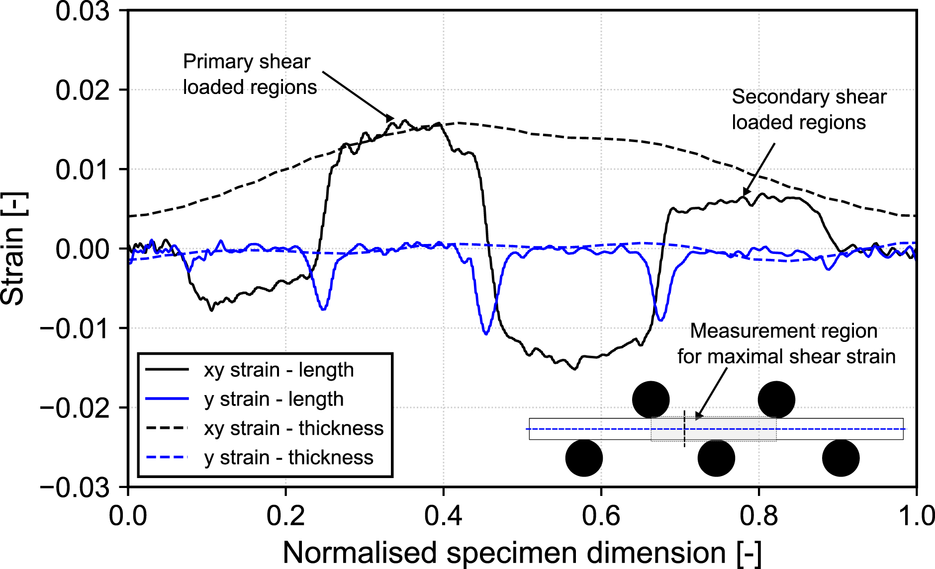
at a framerate of 5 fps for subsequent 2D analysis of the strain field. The load and crosshead displacement were collected from the Zwick testing machine and automatically synchronised with the images from the LIMESS measurement system. The interlaminar shear stress τ can be calculated based on equation (6), in which F is the measured load from the testing machine, b the specimen width and t the specimen thickness. As some specimens possess a non-planar surface, the force signal is pre-treated to remove a potential early non-linear phase resulting from the adjustment of the specimen in the testing device. For this purpose, the force versus displacement signal below a certain force level is replaced by a linear function assuring the continuity of the tangency at this point. In this work, the force level is set to a low value of 50 N. Experimental setup and strain measurement in the five-point bending test (top) and strain state in the specimen length and thickness (bottom).
Most of literature works calculate the ILSS values based on the peak force reached during the test.26,28,29 While this value can be accepted for brittle materials, it does not necessarily coincide with the initiation of delaminations in the specimen for more ductile materials as thermoplastic composites. The determination of a crack initiation criterion is of particular importance in the generation of cohesive zone models in recent finite-element solvers.
30
The present work is based on the evaluation and analysis of the rate of the maximal shear strain in the specimen based on the DIC measurement described in section. The shear strain at crack propagation is estimated at the elbow in the shear strain rate versus displacement curve by calculating and minimizing the distance of every point P of the curve to the line linking the minimum and maximum points, as exemplarily illustrated in Figure 4. After this point, the strain rate accelerates and as a consequence, the cracks propagate faster in the laminate. Based on this value, the respective shear strength at crack initiation is obtained. Additionally, the maximal shear strain and strength at complete specimen failure are calculated. The present approach is particularly suitable and reproducible in the case of mainly monotonically increasing shear strain rates as depicted in Figure 4, which applies to most of the specimens in this work. However, the accuracy of the estimation decreases for specimens with a different shape of the shear strain rate curve. In absence of reliable estimation of the crack initiation via other methods such as DIC, the accuracy of the suggested methodology cannot yet be quantified and will be investigated in further work. Calculation of the ILSS at crack initiation with the elbow point technique.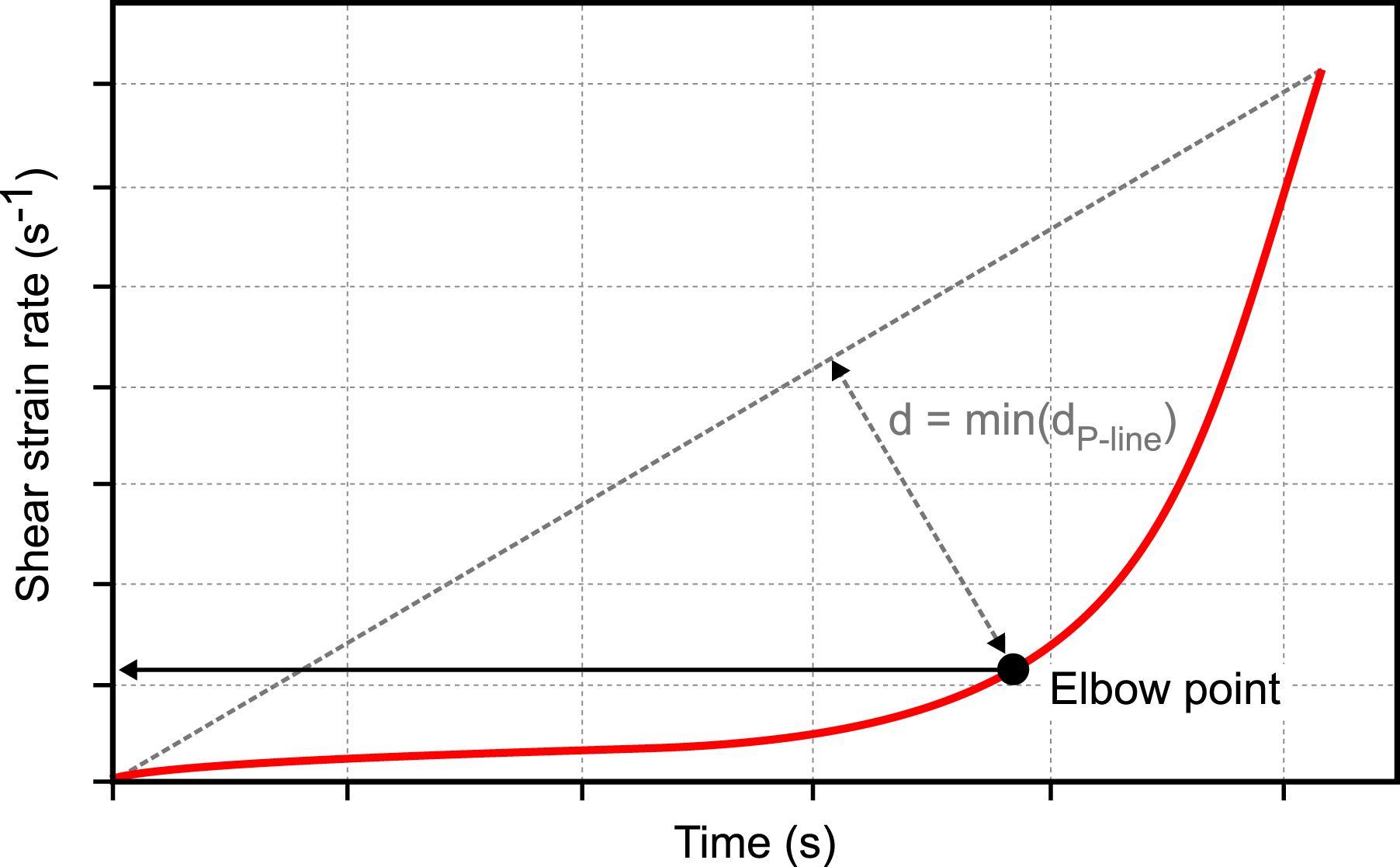
Results
Unprocessed materials
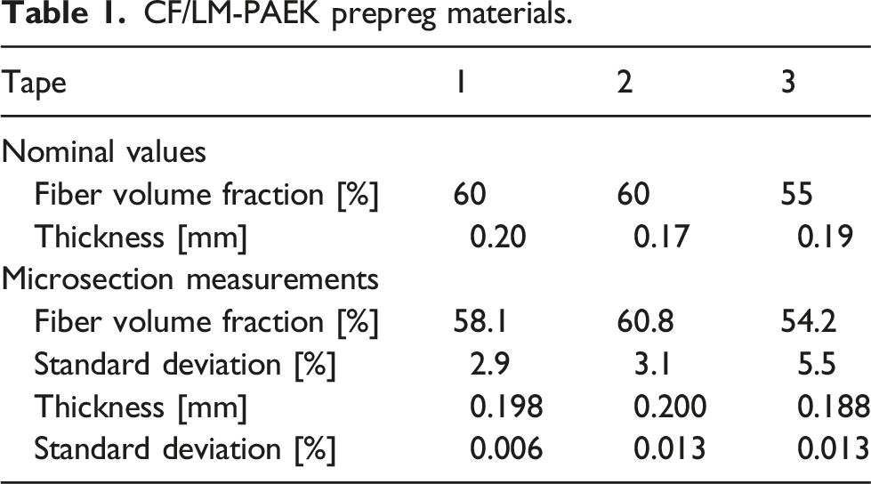
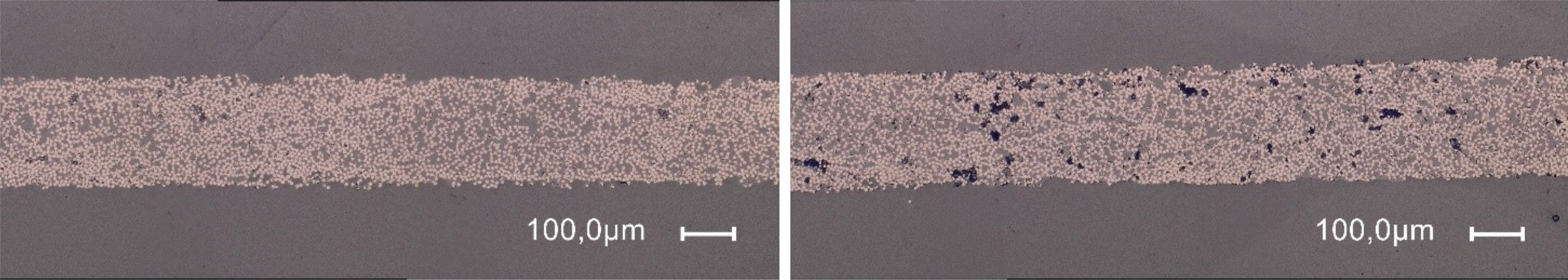
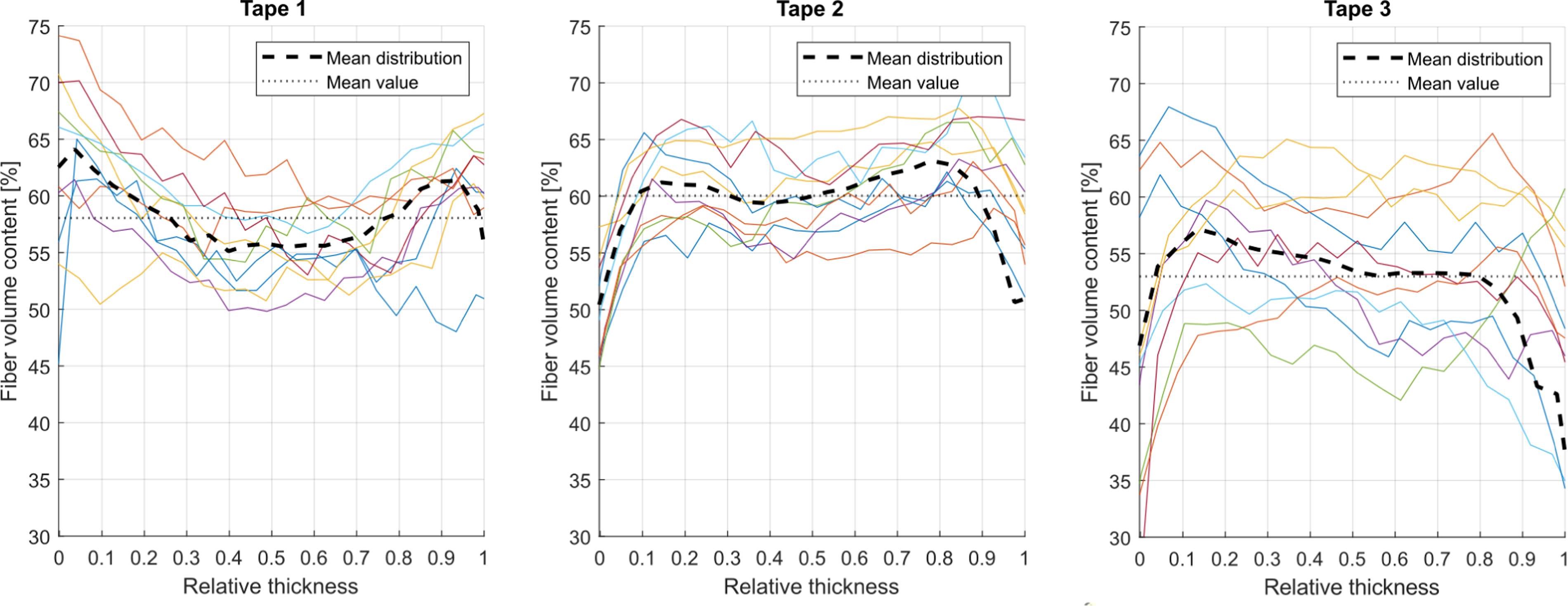
Median tape thickness and fiber volume fraction was determined for each tape, based on the microsection results and are displayed in Table 1. Porosity and surface roughness of the three investigated unprocessed tape materials are presented in Figure 5. Tape 3 has the lowest porosity and surface roughness of 2.3 % and Rz 7.5 µm, respectively. The large standard deviation can be explained by looking at microsections of unprocessed tape material. As can be seen in Figure 6 left and right, which both show microsections of Tape 1, extracted at different positions, tape porosity and surface roughness can vary over the length of the tape. This explains the large standard deviation in Figure 5. Figure 7 shows the fiber volume content distribution over the normalized tape thickness for the three investigated tapes. Each plotted line represents the evaluation of one micrograph. 10 micrographs were analyzed for each tape. The local variation in prepreg composition leads to differences between the 10 fiber volume content curves of each figure. The relative thicknesses of 1 and 0 in the distribution diagrams correspond to the upper and lower tape surface, respectively. The overall mean distribution is shown as a dashed line in the plot. The mean fiber volume content is indicated by a dotted line. The fiber volume fraction deviation from the nominal value can be estimated for the tape surfaces and the tape center. Tape 1 shows local maxima close to 0 and 1 relative tape thickness, thus indicating lower resin content at the tape bottom and top surface, reaching overall fiber volume content of +3 percentage points (pp) at the surfaces and −4 pp at the center with respect to the overall mean fiber volume fraction. Both, Tape 2 and 3 show a gradual decrease in fiber content towards the top and bottom tape surface. Tape 2 and 3 both have a mean value of −6 pp at the surfaces and +−0 pp at the center, which corresponds to a resin-rich tape surface. Porosity and roughness of unprocessed prepreg tape materials. Microsection of tape 1 section with low (left) and high porosity (right). Fiber volume content distribution over tape thickness of unprocessed prepreg tapes.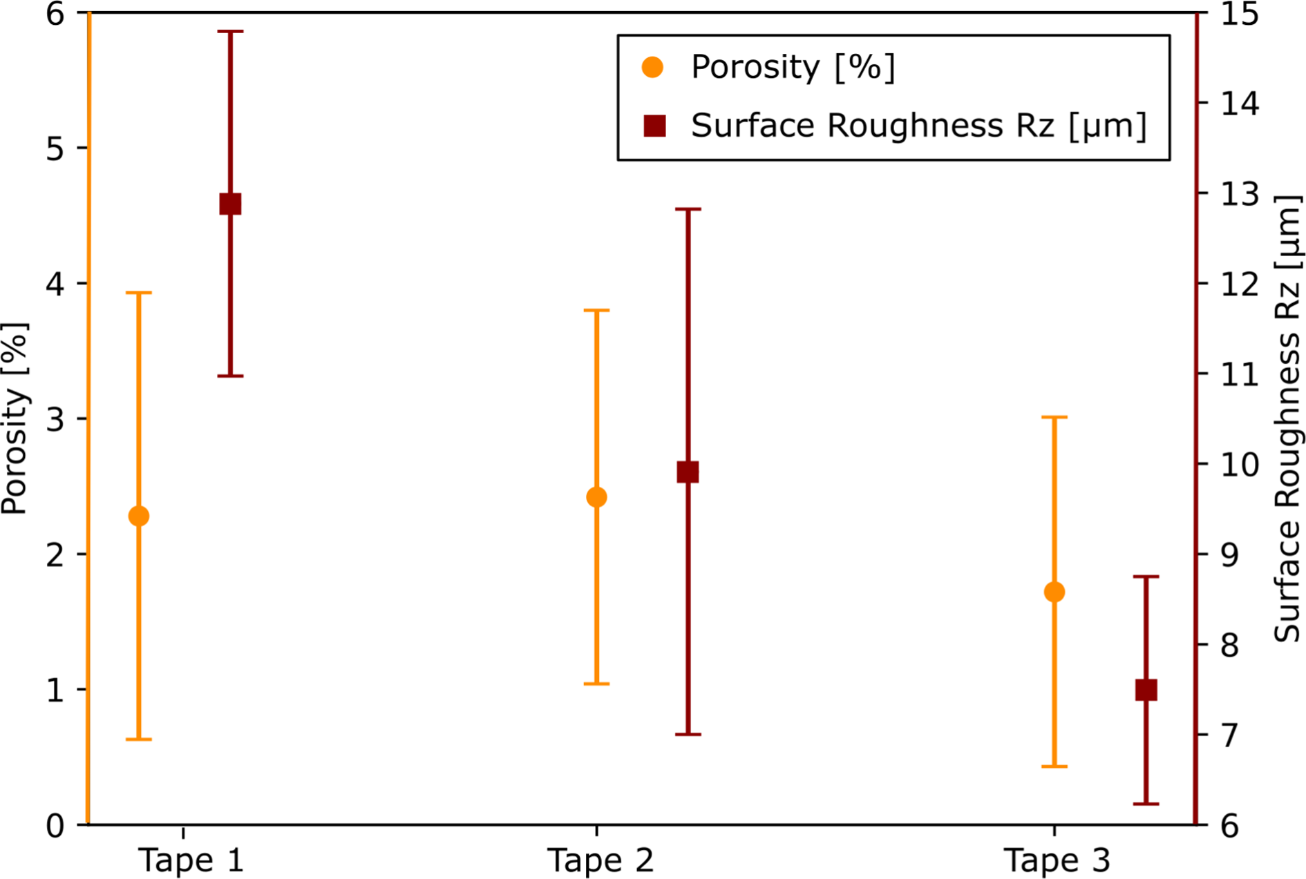
Consolidated laminates
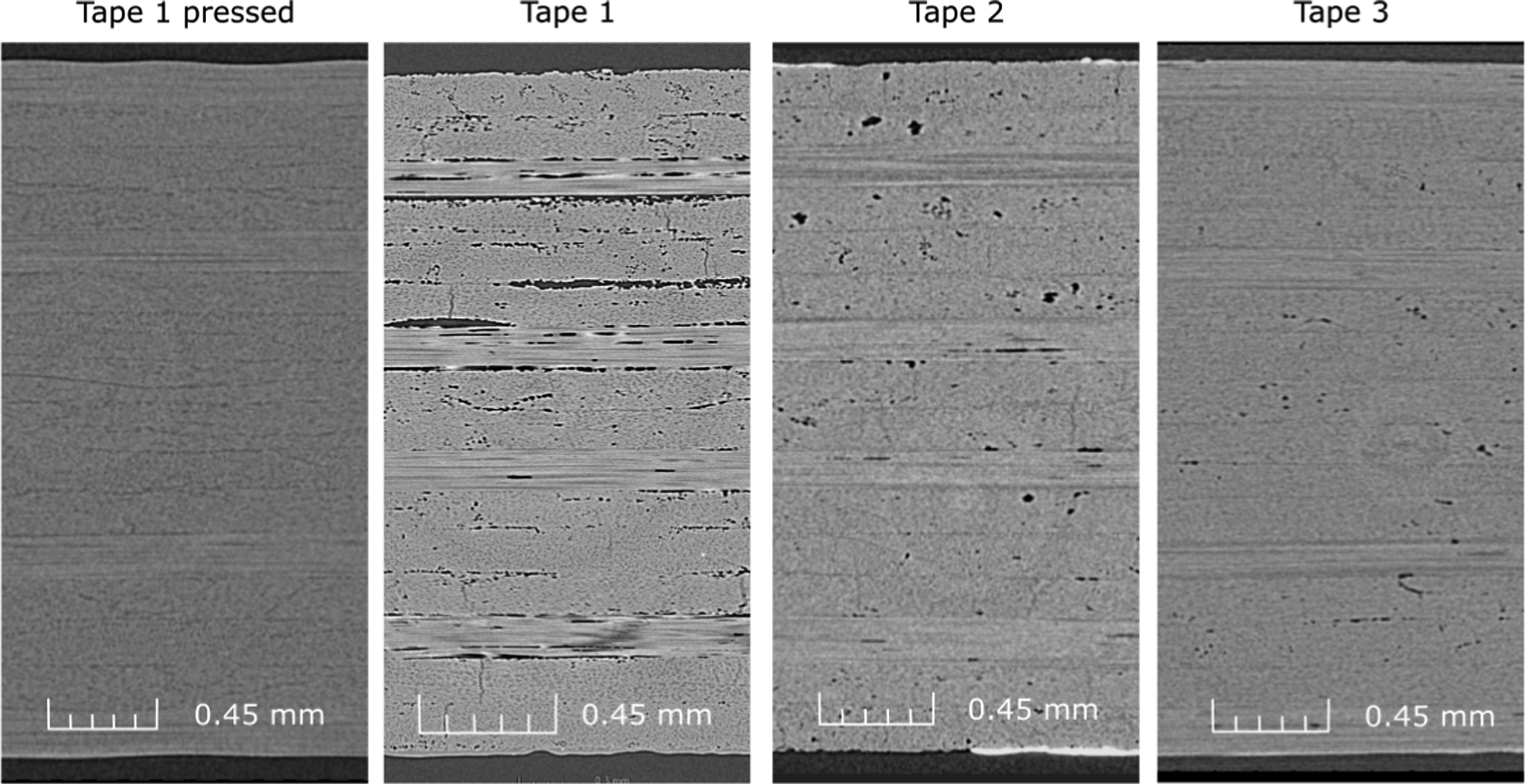
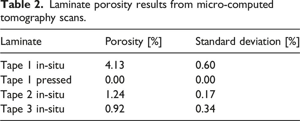
Overall laminate consolidation quality was at first assessed using phased array ultrasonic testing, before moving on to more detailed microanalysis and mechanical testing. Ultrasonic test results of all four laminates are shown in Figure 8. The depicted backwall echo C-Scans represent the proportion of amplitude received with respect to the input signal. The press-consolidated laminate shows the lowest attenuation and a uniform backwall echo across the entire laminate. In contrast, the Tape 1 laminate without post consolidation has the highest attenuation and lowest backwall echo signals, indicating suboptimal consolidation. The Tape 2 laminate shows significantly lower attenuation and better backwall signal than the Tape 1 laminate. The partially bad results can be attributed to poor surface coupling. In comparison, the Tape 3 laminate has slightly lower overall backwall signal with more pronounced attenuation at the track boundaries, resulting in a more distinct cross-ply pattern. Micro-computed tomography scans of the four laminates are depicted in Figure 9. The press-re-consolidated Tape 1 laminate shows no porosity and delamination at all. In comparison, the Tape 1 in-situ consolidated laminate shows significant interlaminar porosity and a noticeable degree of intralaminar porosity. In the upper half of the laminate, there are areas of full delamination. Small vertical cracks can be observed throughout the laminate. Both, Tape 2 and Tape 3 laminates exhibit good consolidation with very low interlaminar porosity. The tape 2 laminate, however, has a significant number of larger-sized intralaminar pores. While only excerpts of the micro-computed tomography data can be presented here, the porosity analysis considers the entire three-dimensional sample volume by evaluating the image stacks of 500 to 800 section views per scan. The porosity results are presented in Table 2. The porosity of Tape 1 hot-pressed laminate was not detectable from micro-computed porosity results. This is supported by literature results. Comer et al. similarly found non-detectable porosity in autoclave-consolidated laminates, using micro-computed tomography with a voxcel size of 0.81 μm.
2
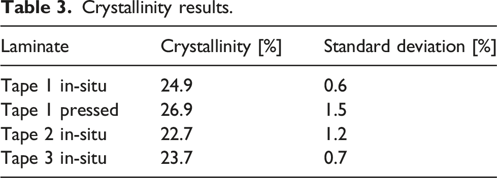
Tape 1 in-situ consolidated laminate has the highest porosity value of 4.13 %. The Tape 3 laminate reaches the lowest porosity of the in-situ consolidated laminates at 0.92 %. Crystallinity results are plotted in Table 3. The press-consolidated laminate reaches the reference value of 27 %. All three in-situ laminates have slightly lower crystallinity, with the Tape 1 material reaching the highest value of 24.9 %. C-scan phased array backwall ultrasonic test results. Micro-computed tomography scans of four manufactured laminates. Laminate porosity results from micro-computed tomography scans. Crystallinity results.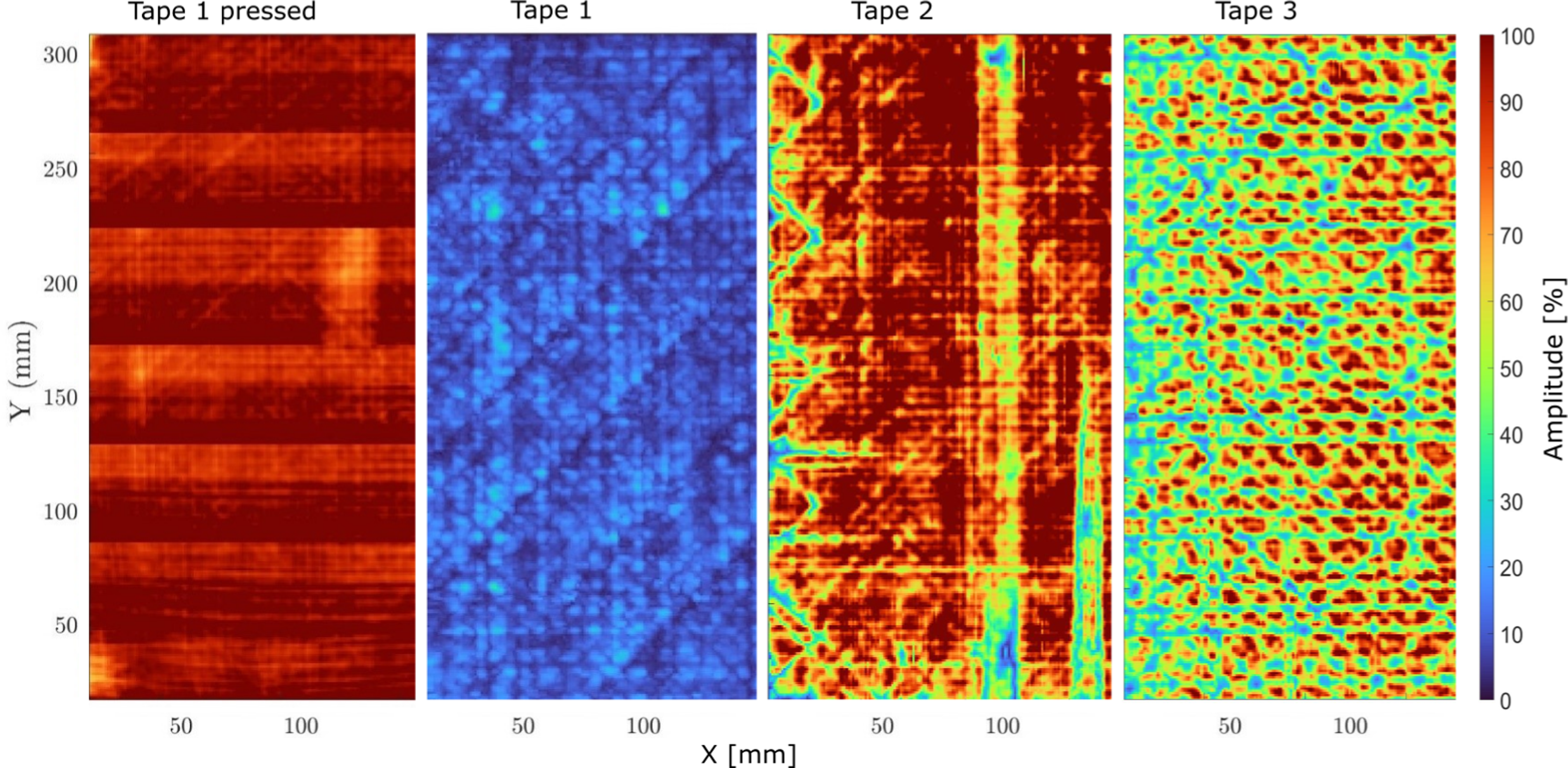
Mechanical performance
Interlaminar shear test results
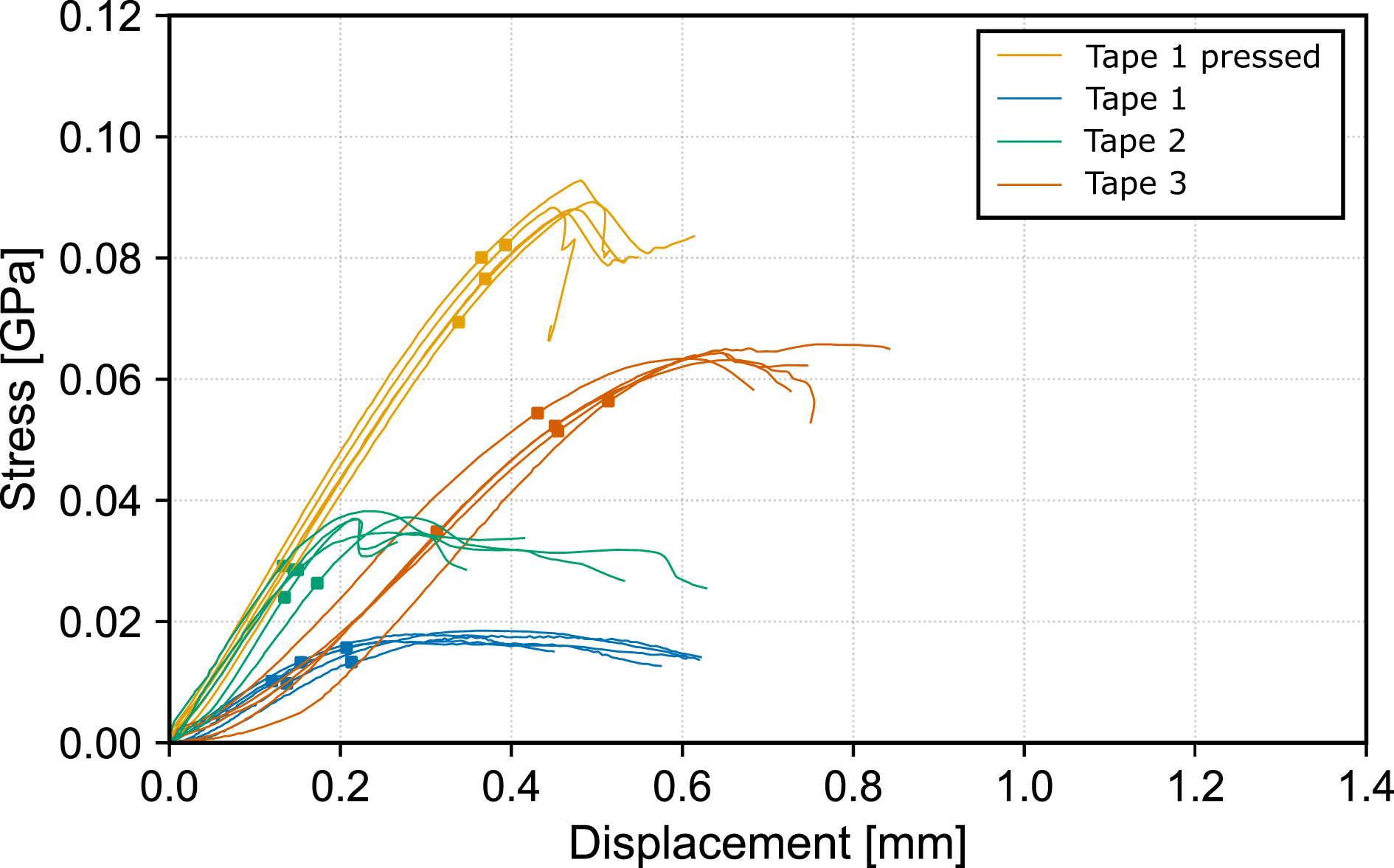
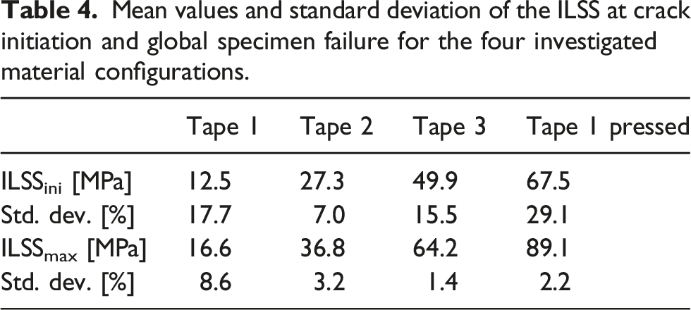
Overall, and considering the unevenness of some of the specimens, the five-point bending tests showed a strong reproducibility and all specimens failed in delamination within the principal pure shear region (Figure 10), while the amount and criticality of the delaminations depended on the material type and plate processing. Only one specimen failed prematurely with a bridging of two delamination in thickness direction (Figure 10 bottom). The stress versus displacement curve is strongly dependent on the tested configuration (Figure 11). The press-re-consolidated laminate configuration reaches the maximal strength of 89.1 MPa, while the in-situ consolidated specimens of the same Tape 1 material without post consolidation show the lowest strength of 16.6 MPa. Exemplary delamination without bridging (top) and delamination with bridging (bottom) in a double beam shear specimen. Stress versus displacement curves for all investigated material configurations; the markers represents the initiation of delamination in the specimens based on the criterion in section.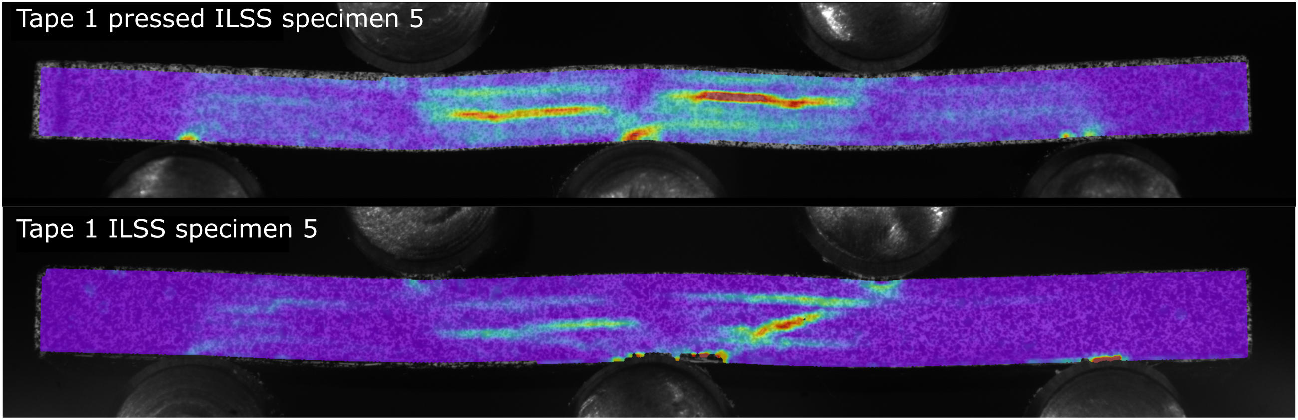
Mean values and standard deviation of the ILSS at crack initiation and global specimen failure for the four investigated material configurations.
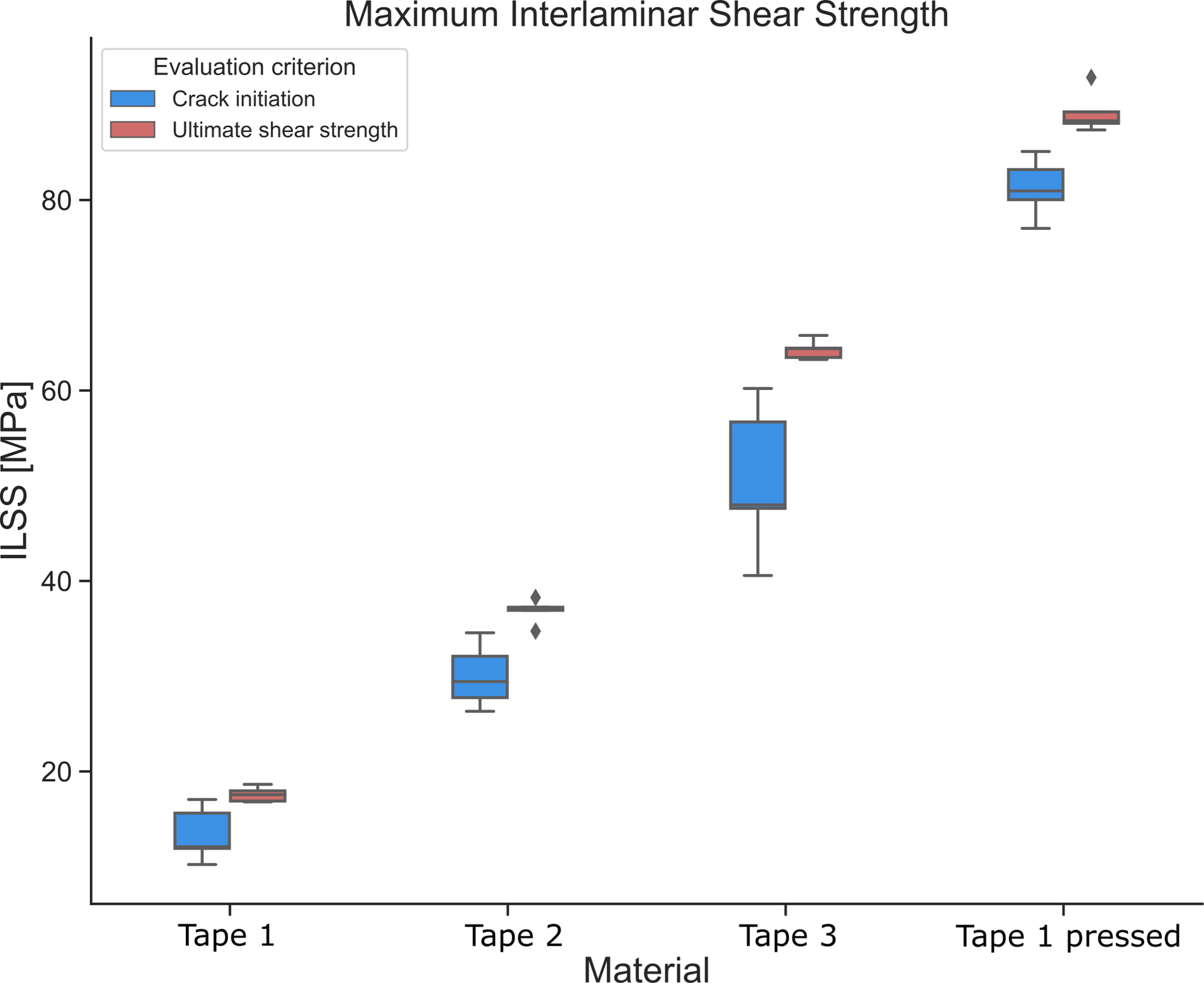
Interlaminar Shear Strength Results from 5-point-bending tests at crack initiation and ultimate shear strength results.
Tensile and compressive test results
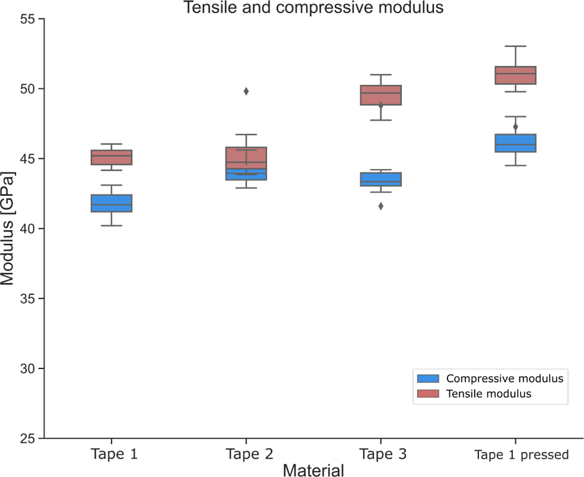
Figures 13 and 14 show the tensile and compressive strength and modulus results, respectively. A similar tendency as in the 5-point-bending results is observed in the tensile strength results, however the magnitude is much lower with a 43 % increase between the in-situ consolidated and the hot-pressed Tape 1 material. The Tape 3 laminate achieves the highest tensile strength out of the in-situ consolidated laminates with 82 % of the hot-pressed reference, despite the lower fiber volume fraction of 55 %. While there is a larger standard deviation in the compressive strength results, the results are still statistically significant. A similar tendency as the in 5-point-bending and tensile test results is again observed, with Tape 1 and Tape 3 reaching 64 % and 88 % of the hot-pressed reference strength, respectively. At 76 % of the reference strength, the Tape 2 laminate again performs lower than the 55 % material. The tensile modulus results confirm these findings with the Tape 3 laminate again reaching the highest result of the in-situ consolidated laminates at 97 % of the hot-pressed reference. The compressive modulus results show very similar values for the Tape 2 and Tape 3 material at 96 % and 94 % of the hot pressed reference modulus. Tensile and compressive strength test results. Tensile and compressive modulus test results.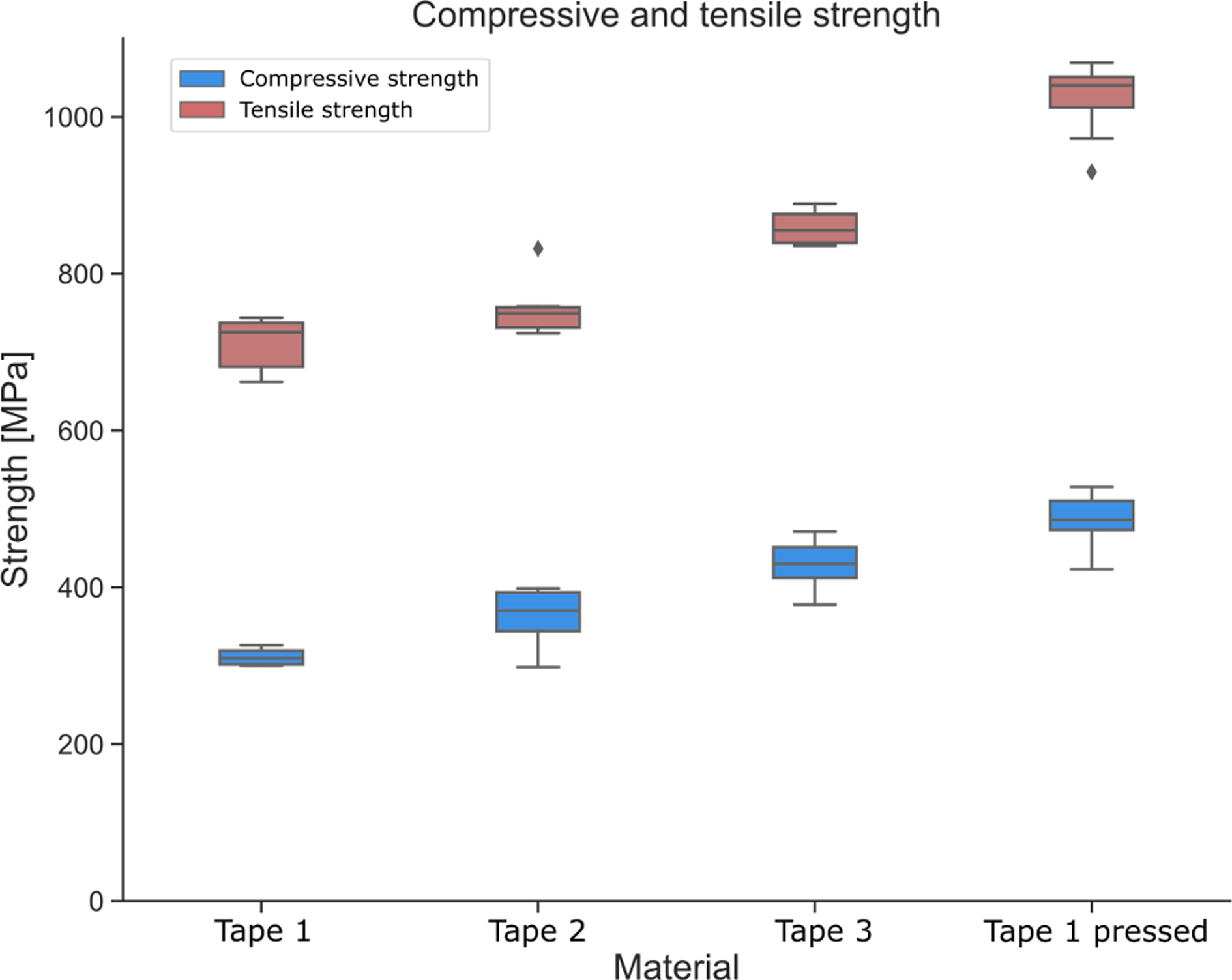
Discussion
The consolidation quality and mechanical properties achieved are highly dependent on the prepreg tape composition. Since only the surface of tape and substrate are heated in the in-situ AFP process, the porosity of the prepreg tape directly affects intralaminar porosity of the in-situ consolidated laminates. Similarly, the surface roughness of the prepreg tape affects the interlaminar porosity of the consolidated laminate. Tape 1 has the highest surface roughness and high internal porosity and thus results in a laminate with high inter- and intralaminar porosity. Furthermore, the Tape 1 material has the highest fiber volume fraction at the tape surface, which equates to lower tape surface resin content. The elevated surface roughness and low surface resin content amount to low effective intimate contact as defined by Celik et al.15,16 thus impeding in-situ consolidation. Tape 3 on the other hand, has lower porosity and lower surface roughness, as well as higher resin content at the tape surface. Consequently, the resulting laminate has significantly better consolidation and lower overall porosity of 0.92 %. Tape 2 has similar porosity but significantly lower surface roughness as compared to Tape 1 and fiber volume content distribution across the tape cross section similar to Tape 3. The resulting laminate thus has little interlaminar porosity, elevated intralaminar porosity and the overall porosity is slightly higher than the Tape 3 laminate. A correlation between input tape porosity, surface roughness, resin content at the tape surface and the resulting laminate porosity can be recognized. The mechanical test results correlate with the porosity and microanalysis outcome. The hot-pressed reference laminate yields the highest strength and modulus for all investigated tests. The same order of mechanical strength can be observed for all three tests. Tape 1 reaches the lowest strength values, followed by Tape 2 and Tape 3 achieving the highest of all in-situ results. The impact of the different materials is most evident in the interlaminar shear test results. While the same tendency is observed in the other tests, the magnitude is significantly higher with Tape 1 and Tape 3 reaching 18.6 % and 72.1 % of the hot-pressed reference, respectively. Out of the three tested mechanical properties, interlaminar shear strength is the one that is most sensitive to interlaminar consolidation quality. It is thus coherent that the influence of consolidation quality is most evident in these results. The two more fiber-dominated properties tensile and compressive strength as well as the respective modulus results interestingly show the same trend. Despite the lower fiber content, Tape 3 achieves the highest tensile and compressive strength results at 82 % and 88 % of the hot-pressed reference, respectively. Normalized reference strength values on the basis of nominal fiber volume fraction yield 89 % and 96 % relative tensile and compressive strength, respectively. The remaining knockdown can be explained by in-situ AFP manufacturing signature-induced slight out-of-plane undulations of 0°-plies and slight warpage of in-situ AFP laminates and thus slightly warped tensile and compressive specimens, as opposed to perfectly flat hot-pressed reference specimens. This could result in uneven stress and strain distribution in the four 0°-plies and premature failure in the 0°-ply that is exposed to the highest stress.
As described in the Materials and Methods section, the utilized fibers are very similar in both strength and modulus. The Crystallinity results of the in-situ manufactured laminates are also very similar and on a sufficiently high level. The higher mechanical performance compared to the two other higher fiber volume fraction materials is thus to be attributed to the lower porosity and better consolidation of the Tape 3 laminate. A comparison to a hot-pressed reference of the same Tape 3 could arguably yield even higher proportions of in-situ results compared to hot-pressed reference and will be subject to future investigations. Based on this dataset the assumption can be made, that in-situ consolidation might benefit from lower fiber volume fraction material, if this allows for better quality tape in the form of higher surface resin content, lower porosity and lower surface roughness. Limited laminate level in-situ AFP tensile and compressive test results are available in the literature. Similar compressive strength of up to 481 MPa was found by Lamontia et al. for in-situ consolidated AS4/PEEK quasiisotropic laminates. Between 92 % and 97 % of autoclave reference strength were reported.31,32 For hot-press-consolidated T700 GC/LM-PAEK laminates, quasiisotropic tensile strength of 972 MPa and 531 MPa compressive strength were found. 24 Similar impact of prepreg composition on consolidation quality and interlaminar shear strength was found in the literature.2,17,23,32–34 Smooth-surfaced AFP-grade tape achieved better intimate contact and higher degree of bonding, 13 even outperforming autoclave reference specimens in some studies.32,33 Limitations of this work include the number of investigated prepreg tape materials. Further materials are going to be investigated in future work. Also the mechanical testing in this study was limited to laminate level tensile and compressive tests, as well as five-point-bending ILSS testing. While these tests were successfull in demonstrating the effect of prepreg composition on resulting laminate consolidation quality, further mechanical properties such as fracture toughness could supplement the study. A second hot-pressed reference laminate using the 55 % fiber volume fraction material could complement the work, proving the point of lower knockdown factors for AFP-grade prepreg material. The porosity analysis of unprocessed tape materials and consolidated laminates is based on microsections and micro-computed tomography scans. A reference porosity analysis method such as resin digestion could validate these results.
Conclusion
In Part 1 of this work, different in-situ AFP processing routes were compared in terms of their mechanical performance. A 200°C heated tooling configuration was found to yield the best mechanical properties out of the in-situ consolidated laminates. However, there was a significant knockdown compared to the hot-pressed reference laminate. One limiting factor of these initial results was the sub-optimal prepreg tape quality, which did not allow for optimal in-situ consolidation. The impact of prepreg tape quality was thus subsequently investigated in Part 2 and is presented in this paper. In the first section of this paper, a methodology was presented to quantify the composition of prepreg tape in terms of porosity, surface roughness and fiber distribution across the tape. The methodology was successfully demonstrated for three different prepreg tape materials. Laminates were manufactured in the second section and the resulting mechanical properties were correlated with the respective prepreg tape composition. A correlation between input tape composition and resulting laminate consolidation quality was established. Higher porosity and surface roughness as well as lower surface resin content led to insuffiecient consolidation in the in-situ AFP process and inferior mechanical properties. The use of 55 % fiber volume fraction AFP-grade tape led to better consolidation results and mechanical performance, reaching 82 % and 88 % of hot-pressed reference tensile and compressive strength, respectively. In-situ consolidation quality likely benefits from lower fiber volume fraction prepreg tape, if this allows for higher resin content at the tape surface, lower surface roughness and overall porosity. The standard three-point bending ILSS test led to non-standard failure modes in Part 1 of this work and was replaced with a five-point bending test, which produced very good results. Digital Image Correlation showed pure shear failure consistent with the test standard. Very low standard deviation was achieved for ultimate ILSS strength evaluation. A crack initiation evaluation methodology using Digital Image Correlation supported the ultimate strength results. The ILSS test results turned out to be the most sensitive to consolidation quality which was assesed in micro-computed tomography and ultrasonic scans. Only 18.6 % of reference strength was achieved for the Tape 1 material. Tape 3 achieved 72.1 % of hot-pressed reference strength. Future work will focus on further improving the in-situ AFP process to get even closer to hot-pressed reference strength values. Furthermore, the methodology will be validated for additional materials.
Footnotes
Declaration of conflicting interests
The author(s) declared no potential conflicts of interest with respect to the research, authorship, and/or publication of this article.
Funding
The author(s) disclosed receipt of the following financial support for the research, authorship, and/or publication of this article: This work was supported by the This project has received partial funding from the Clean Sky 2 Joint Undertaking (JU) under grant agreement No. 945,583. The JU receives support from the European Union’s Horizon 2020 research and innovation programme and the Clean Sky 2 JU members other than the Union. This research is part of the project ICASUS (Integrated Cabin Airframe System Fuselage) including the MFFD (Multi-Functional Fuselage Demonstrator) and was financially supported by the European Commission through the Clean Sky 2 Joint Undertaking (JTI-CS2_CPW01-LPA-02-01). This research is also part of the project FFS (Fortschrittliche Flugzeugstrukturen) which is financially supported by the German Federal Ministry of Defence.
Disclaimer
The results, opinions, conclusions, etc. Presented in this work are those of the author(s) only and do not necessarily represent the position of the JU; the JU is not responsible for any use made of the information contained herein.