
Abstract
Traditional failure criteria for composites are usually formulated in material coordinates and depend on all three inplane stresses, hence failure evaluation depends on the ply angle. The omnistrain failure envelope describes the most critical failure envelope in strain space irrespective of ply orientation. This independence of ply orientation leads to an isotropic failure criterion that depends only on the principal strains. Omnistrain envelopes greatly simplify the task of design and optimisation of composite laminates. This paper proposes a numerical technique to generate omnistrain failure envelopes for different composite failure criteria. The failure index, describing how far a point in strain space is from the failure boundary, is used to describe the failure surface. Assuming convexity of the failure surface, a set of points is generated on the surface, and the convex hull algorithm is used to generate a polygonal approximation of the failure surface. Representing strains in terms of principal strains and the angle between the principal and material coordinates, allows us to eliminate the angle analytically by considering the worst case condition. The omnistrain envelope is thus directly generated from the approximate three-dimensional failure surface. The proposed algorithm does not require analytic expressions of the failure surface. An adaptive algorithm is proposed to generate the omnistrain envelope with relatively small number of points. As demonstration of the proposed algorithm, the omnistrain envelopes for various composite materials are generated for a number of composite failure criteria. The omnistrain envelopes generated for the Tsai-Wu criteria accurately match to existing analytic expressions.
Introduction
Strength of conventional Engineering materials such as Aluminum, Copper, Steel etc., can be dealt with as a unique value regardless of loading and dimensions. However, special attention should be given when assessing failure in composite materials, due to their non-homogeneity and anisotropy. Strength properties and failure mechanisms of composite materials, change with the direction of loading which makes the problem more complicated. Many theories have been developed for decades to predict the failure for fiber reinforced composites either in lamina or laminate. A set of theories, such as maximum stress and maximum strain criteria, are called limit or non-interactive theories, as they predict failure by comparing individual stress or strain components with corresponding strengths or ultimate strains. There is no interaction between stress or strain components. On the other hand, interactive theories predict failure through formulas that include interactions between all stress or strain components but the mode of failure is still undetermined. The most known interactive criteria that are used till now are Tsai-Hill 1 and Tsai-Wu 2 criteria. The previously mentioned methods did not account for failure modes for matrix and fiber which is covered by failure-mode-based-theories, where separate criteria are given for each constituent. As an example, Hashin 3 proposed to separate matrix failure modes from those of the fiber. For each failure mode or mechanism, tension is distinguished from compression resulting in four distinct failure modes.
Tsai 4 proposed the omnistrain failure envelope which is defined as the most critical inner failure envelope. This idea facilitates the design of composite materials as the generated envelopes are independent of ply orientations. Tsai and Melo 5 generated omni strain last ply failure envelopes based on Tsai-Wu and maximum strain failure criteria. They proposed a unit circle failure envelope for any carbon faiber laminate. Furtado et al 6 predicted the notched strength of carbon/epoxy laminates using invariant-based approached introduced by.4,5 Millen and Aravand 7 assessed the unit circle failure envelope and results showed it was conservative in general.
There were attempts in literature to find analytical expressions of the omnistrain envelopes. Analytical expressions of the omnistrain failure envelopes based on Tsai-Wu failure criteria, have been derived by IJsselmuiden et al. 8 In this paper, omnistrain failure envelopes are generated numerically, instead. This numerical technique can deal with complex failure criteria which includes multiple modes of failure like Hashin failure criteria.
The rest of this paper is organized as follows: section Three dimensional failure Envelopes discusses the properties and the generation of the three dimensional failure envelopes. Section Omnistrain Failure Envelope Generation for Composite Materials proposes a numerical technique to generate the omnistrain failure envelopes from the three dimensional envelope. Section Results presents the resulted omnistrain envelopes based on Tsai-Wu, Hashin and Puck failure criteria. It also includes a comparison between both of the criteria and results from the literature. The results of the adaptive algorithm are also presented in this section. Section Conclusion discuses the conclusion of this paper.
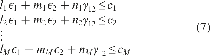
Three dimensional failure envelopes
Three dimensional failure envelopes usually represented in material coordinates in terms of the critical stresses at failure (

The safe region is represented by the following inequality,

Based on the factor of safety definition given in
9
, the failure envelope can be redefined,

Omnistrain failure envelopes are defined in strain space mainly because the failure strains in fiber and matrix directions are comparable, while failure envelopes in stress space are highly elongated. Since the composites in general are brittle, a linear relationship can be assumed between stresses and strains to transform the previous expressions into strain space. Generation of the failure surface from a set of arbitrary points in the strain space. (a) Sampled points of the failure surface. (b) Polygonal approximation of the failure surface.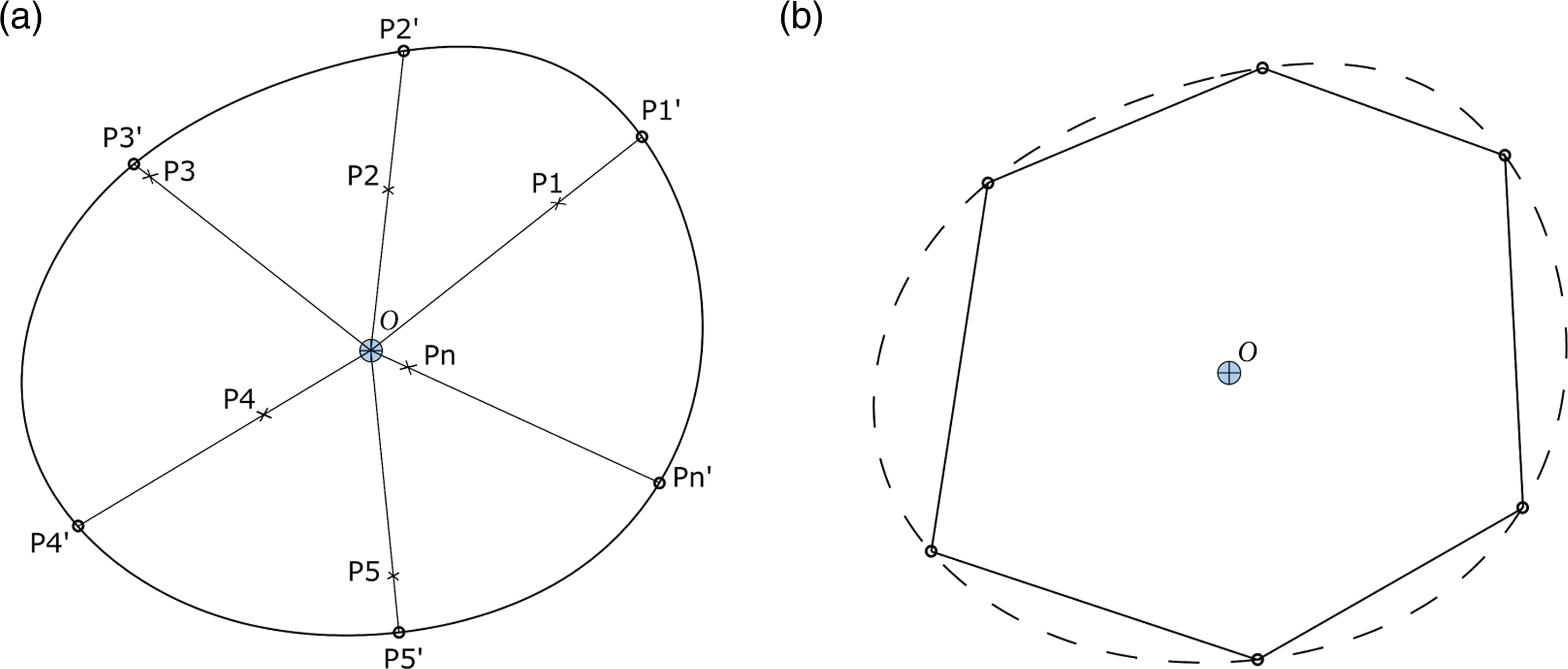

It can be shown that the failure index is the inverse of the factor of safety defined in 9 and is a convex function of strains as proved in appendix Convex Sets and Convex Functions
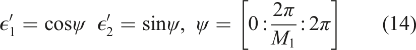
In order to sample the failure surface, a set of points
The failure criteria may be defined by more than one function as in Hashin failure criterion. 3 In this case the failure index is calculated for each function, then the maximum failure index is used. The maximum of multiple failure indices represents the most critical inner intersection of multiple envelopes.
Omnistrain failure envelope generation for composite materials
In the previous section, a convex hull is obtained as an approximation of the failure surface. Convex hull is defined to be the smallest convex enclosure containing a set of points. Each facet of the convex hull is simply a plane with the safe region being a halfspace. The halfspaces of all planes (forming the convex hull) are represented by a set of linear inequalities in the strain space.
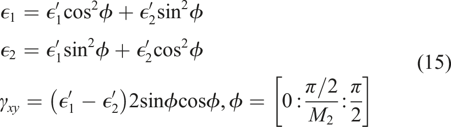
Strains generateds in the previous section were in material coordinates which can be transformed into principal coordinates through the following relations,
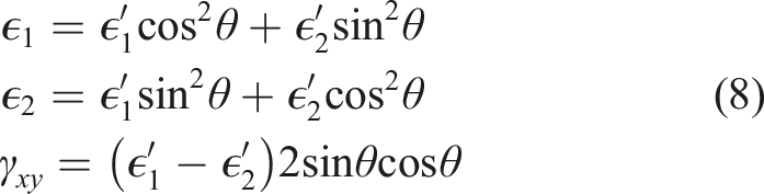
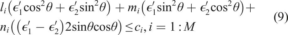
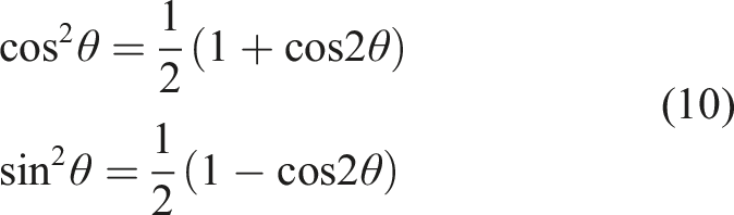
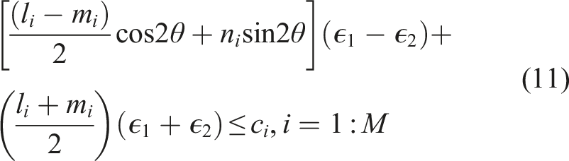
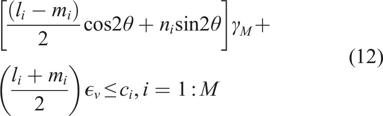
This equation represents a family of linear constraints in the plane ϵ v − γ M parameterized by the angle θ. Variation of the angle represents plies of different orientations at the stacking sequence of the composite. To obtain the omnistrain envelope, the most critical case—out of all the possible constraints—should be considered.
The critical constraint is obtained by maximizing the left hand side with respect to the angle θ. The coefficient of γ
M
is harmonic in θ which means that its maximum is the amplitude. Now the most critical constraint is represented in the following form:
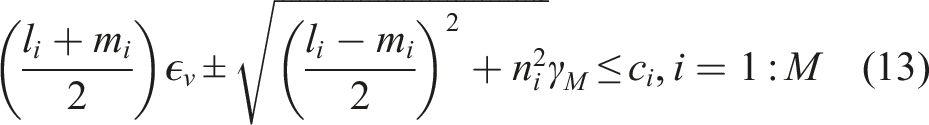
The maximum shear strain γ M can be positive or negative, thus a plus or minus sign is given to the amplitude term. The set of constraints defined by equation (13) represents a polygonal approximation of the omnistrain failure envelope.
Algorithm
(1) Generate a set of arbitrary principal strains (2) All possible rotations of the generated principal strains are obtained using the following equation: 3. For each strain point, the failure index is calculated and a point on the failure surface is defined by equation (6). 4. In the presence of multiple failure modes as in example Hashin, the most critical failure index is the maximum. 5. Using Qhull the convex hull is constructed from the set of strain points 6. Qhull output is set to generate halfspace form resulting in a set of inequalities 7. 7. Each halfspace is used to generate two constraints of the form 13. This set of constraints now represents the halfspace representation of the omnistrain envelope. 8. Run Qhull over the intersections halfspaces to obtain the convex hull of the omnistrain envelope.
Adaptive algorithm
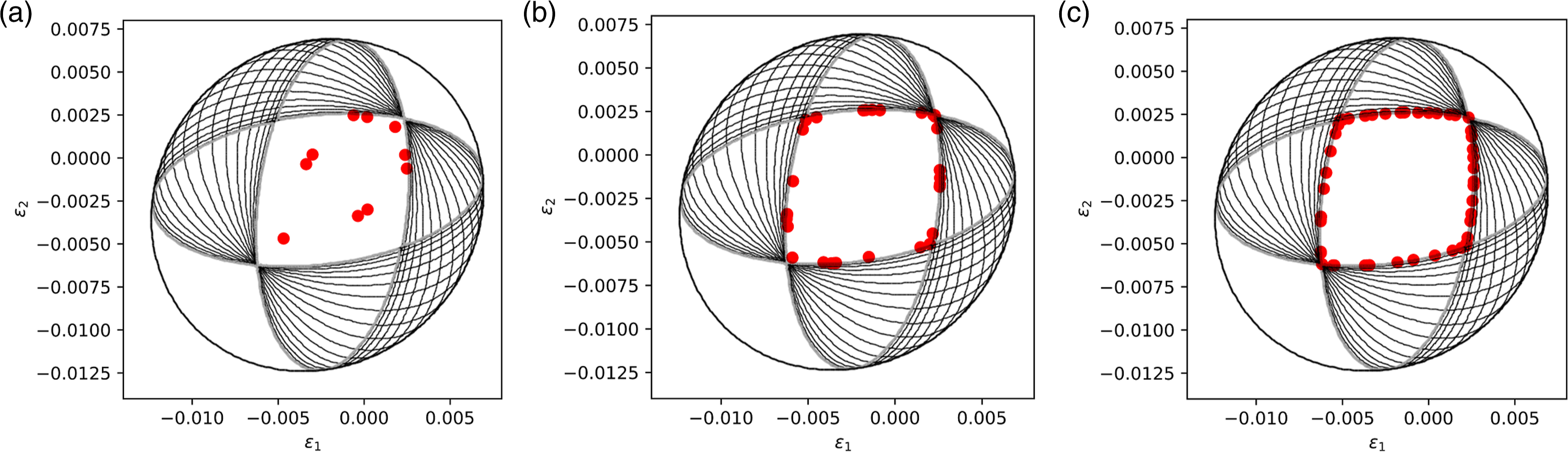
The accuracy of the omnistrain envelopes showed dependence on the number of sampling points. An adaptive algorithm is suggested to minimize the number of sampling points. The algorithm is based on starting with the least number of sampling points in the strain space and evaluating the corresponding points on the failure surface. The convex hull is then obtained as discussed before in section Algorithm. The convex hull consists of a set of triangles. Then, the centroid of each triangle is defined. The failure index will be calculated for these centroids. Five percent of these centroids which have the lowest failure indices, will be chosen and added to the sampling points as shown in Figure 2.
1
The error is defined as follows: Application of the adaptive algorithm on the polygonal approximation of the failure surface. (a) Polygonal approximation of the failure surface. (b) Polygonal approximation of the failure surface after applying adaptive algorithm.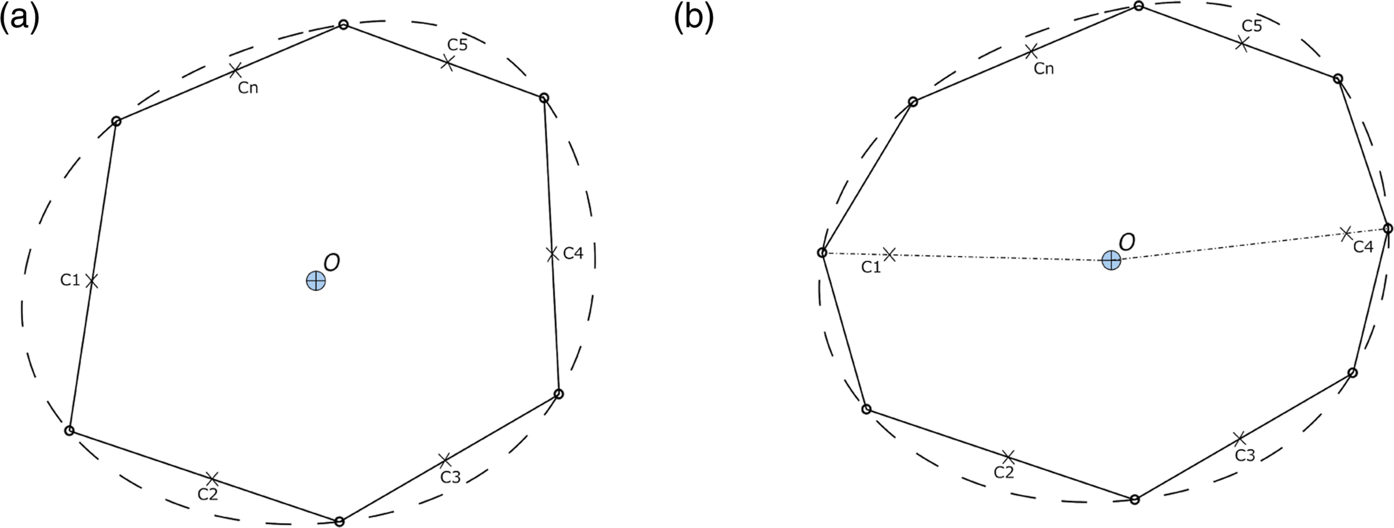

The algorithm is repeated until a threshold on the error value is achieved.
Results
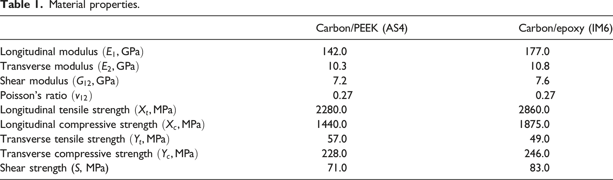
Material properties.
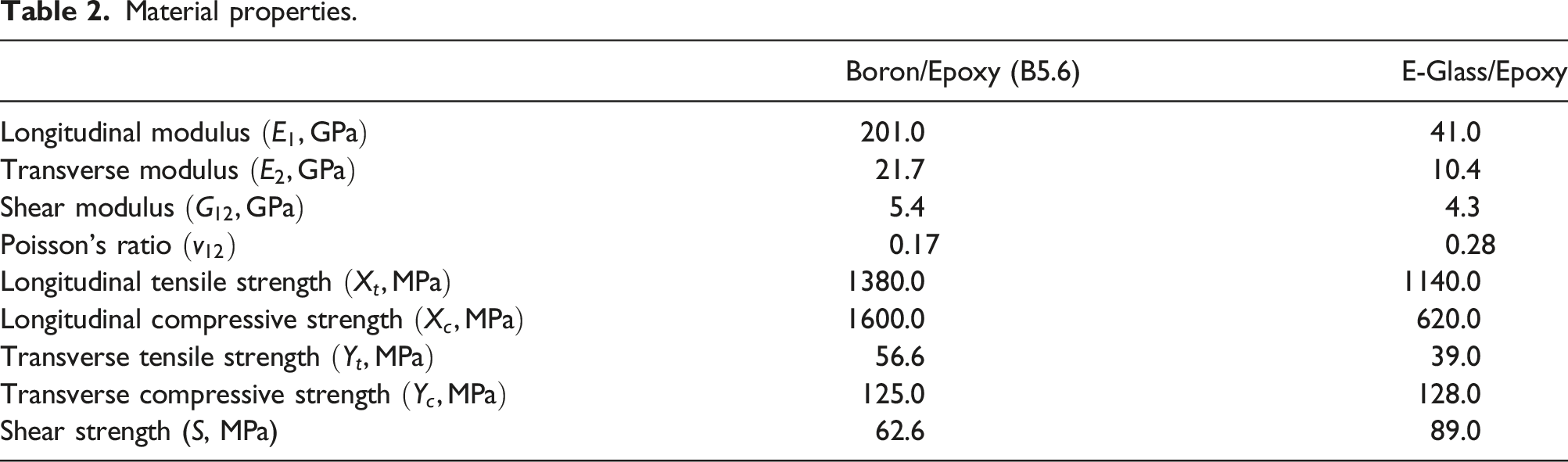
Material properties.
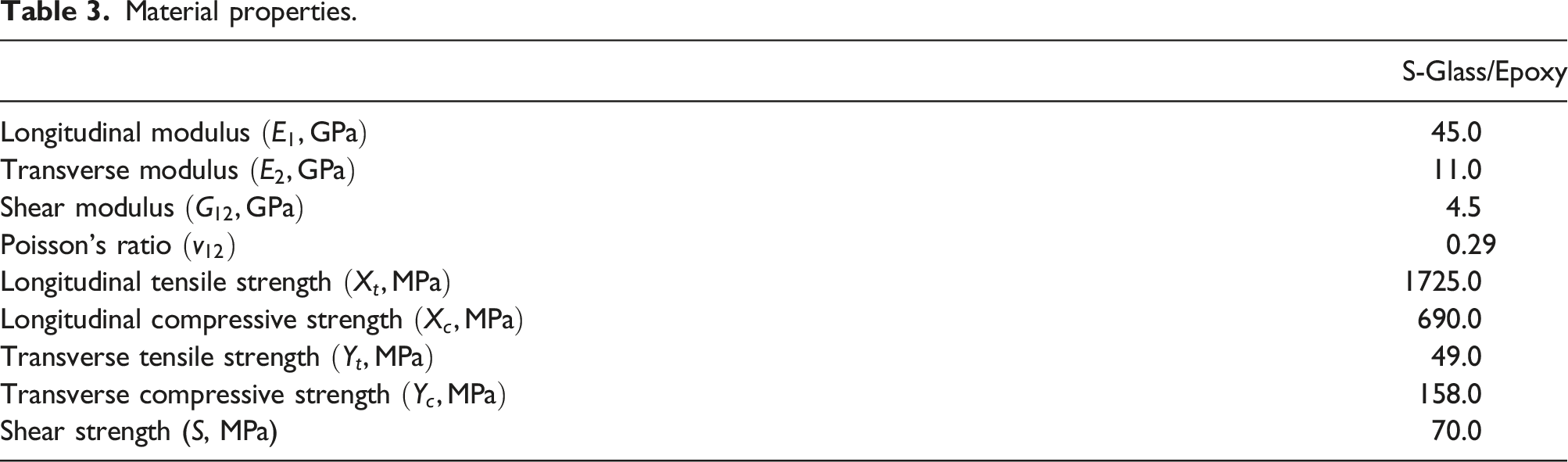
Material properties.
Tsai-Wu failure criteria
The analytic expressions of the omnistrain failure envelopes of Tsai-Wu failure criterion are generated in.
8
Incorporating these expressions into the algorithm stated in section Algorithm for a different number of sampling points, Figures 3, 4 and 5 are obtained. Carbon peek. (a) M = 2500 (b) M = 625 (c) M = 144. Tsai-Wu strain envelopes for θ = 0, 5, …, 90 deg Carbon Epoxy. (a) M = 2500 (b) M = 625 (c) M = 144. Tsai-Wu strain envelopes for θ = 0, 5, …, 90 deg Boron Epoxy. (a) M = 2500 (b) M = 625 (c) M = 144. Tsai-Wu strain envelopes for θ = 0, 5, …, 90 deg  . Omnistrain envelope based on Tsai-Wu failure criteria
  .. Omnistrain envelope based on Tsai-Wu failure criteria .. Omnistrain envelope based on Tsai-Wu failure criteria .
In analytic expression based on the type of material, there exists two types of envelopes. One type is essentially an ellipse as shown in Figures 3(a) and 4(a). The other type is an intersection of two ellipses as in Figure 5(a). The previous results prove the robustness and the ability of the algorithm to track the envelope irrespective of the shape of the envelope. Additionally, they clearly show that fewer sampling points result in increasing error as shown in Figures 3(c), 4(c) and 5(c).
Adaptive algorithm
In this section, omnistrain failure envelopes are generated for Carbon Peek and Boron Epoxy using the adaptive algorithm as shown in Figures 6 and 7. Clearly, Figures 6(c) and 7(c) exhibit results that are remarkably congruent with those depicted in Figures 3(a) and 4(a), respectively. This observation is noteworthy as Figures 6(c) and 7(c) were generated using a significantly reduced number of sampling points. The profound similarity between the two sets of results serves as a proof of the computational efficiency of the algorithm and its ability to achieve comparable outcomes while operating with a reduced computational cost. Adaptive algorithm results at different correction steps for Carbon Peek (a) Step 1, M = 9, Error = 61.45% (b) Step 21, M = 72, Error = 6.61% (c) Step 42, M = 532, Error = 0.94%. Adaptive algorithm results at different correction steps for Boron Epoxy (a) Step 1, M = 9, Error = 72.29% (b) Step 21, M = 72, Error = 6.46% (c) Step 41, M = 493, Error = 0.96%.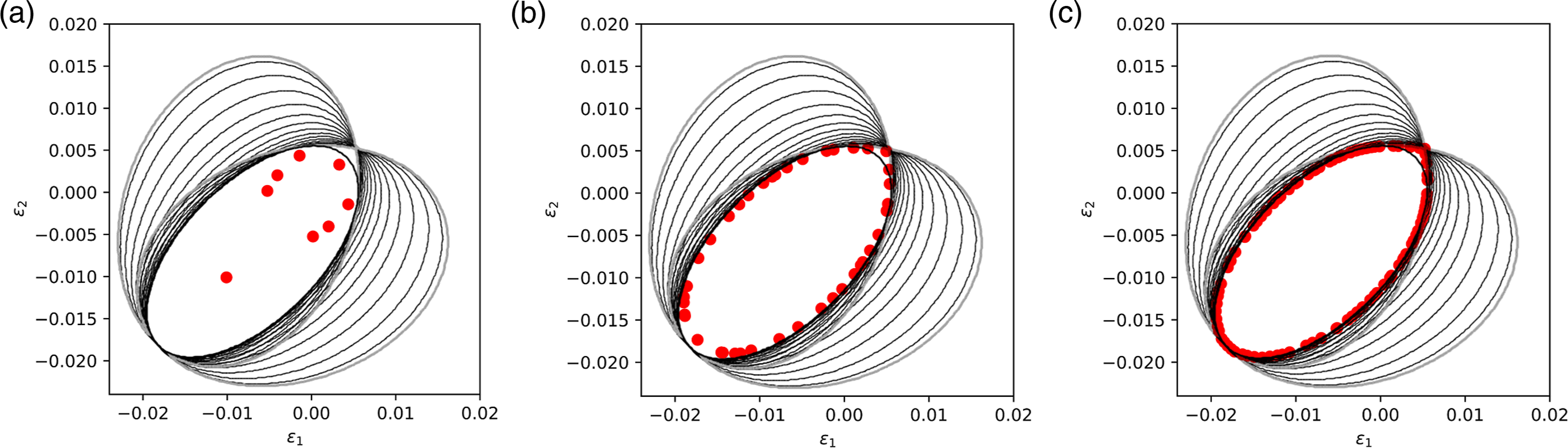
Comparison of different failure criteria
The analytic expressions derived in the appendices are used to generate the curves of Figures 8, 9, 10, 11 and 12. Comparison between different failure criteria (Hashin failure criteria Comparison between different failure criteria (Hashin failure criteria Comparison between different failure criteria (Hashin failure criteria Comparison between different failure criteria (Hashin failure criteria Comparison between different failure criteria (Hashin failure criteria , Tsai-Wu failure criteria , Puck failure criteria  )., Tsai-Wu failure criteria , Puck failure criteria
  )., Tsai-Wu failure criteria , Puck failure criteria )., Tsai-Wu failure criteria , Puck failure criteria )., Tsai-Wu failure criteria , Puck failure criteria ).
It is clear that Hashin is more conservative than Tsai-Wu in the third quadrant which represents the compression-compression case.
Conclusion
Numerical generation of omnistrain failure envelopes based on different failure criteria is presented. Three dimensional failure surfaces are constructed as a polygonal approximation of sampled failure points in the strain space. Sampling the points of the three dimensional failure surface relies on calculating the failure index, which is proved to be a convex function, and does not require a functional description of the failure surface. As a result, omnistrain envelopes can be generated for any failure criteria including those that are not defined by a single analytical expression such as Hashin criteria. The number of sampling points highly affects the accuracy of the generated envelopes. Results based on Tsai-Wu failure criteria showed a great match with analytic expressions regardless the shape of the envelope. Comparison between Hashin criteria and Tsai-Wu criteria showed that Hashin criteria is more conservative in the third quadrant (compression-compression) and is very close to Tsai-Wu criteria in the other quadrants.
Discussion
This work presents a strain-based failure criterion. The developed omnistrain envelopes take advantage of the invariance of failure envelopes in strain space. Hence, a master failure envelope can be developed for a laminate in strain space, regardless of the layup. Being expressed in terms of strain makes it more robust and universal as strains are almost constant at the onset of irreversible damage. Unlike stresses, which vary dramatically at failure, depending on deformation mode, strains are almost identical and independent of failure mode or the load type. Strains can also be easily measured through experiment and calculated using different laminate theories, rather than using arbitrary assumed parameters that were used for fitting envelopes on test data 11 . Moreover, strains represent a physical meaning related to deformations.
The proposed methodology allows for evaluating the most critical omnistrain failure envelope by comparing different failure criteria as shown in Figures 8, 9, 10, 11 and 12. Additionally, it opens the door for using criteria that deal with composite materials as two discrete constituents (matrix and fiber), such as the Strain Invariant Failure Theory (SIFT) 11 , where each constituent needs to be assessed for each failure mode independently. It is assumed that both kinds of deformation modes (distortion and dilatation) are coexisting. The focus should be on which mode will become critical first and in which constituent (fiber or matrix). Furthermore, the scope of this research can be extended to incorporate plasticity as in this work only brittle composites were considered. Moreover, an enhancement could be made by incorporating time-dependent failure criteria into the study.
Footnotes
Author’s notes
This publication is dedicated to the memory of our esteemed coauthor, Dr. Mostafa Abdalla, who regrettably passed away on July 2023. Dr. Mostafa left an indelible mark on the field of composite materials and structural optimization. Dr. Mostafa's academic journey spanned continents, from Cairo University to Virginia Tech and Delft University of Technology, where he earned his PhD. Finally, he was a full professor at Zewail City of Science and Technology in Egypt, where he held the position of Head of the Department of Aerospace Engineering.
Dr. Mostafa was renowned for his pioneering contributions to the optimization of composite materials, particularly in the context of aerospace applications. His remarkable insights and ingenuity paved the way for revolutionary advancements in the design and manufacturing of composite structures. Notably, his work on optimizing fiber-steered laminates, which entail an intricate design space, remains invaluable to composite and aircraft manufacturers worldwide.
Beyond his remarkable scientific achievements, Dr. Mostafa's warm and inspiring personality touched the lives of his colleagues, students, and friends alike. His wisdom, patience, humanity, and kindness serve as a guiding light for all who had the privilege of knowing him.
This publication is a tribute to Dr. Mostafa Abdalla's enduring legacy, a legacy of innovation, generosity, and brilliance that will forever resonate in the field of composite materials. His legacy lives on through his publications and the enduring impact of his work. We fondly remember his contributions and the remarkable person he was.
Declaration of conflicting interests
The author(s) declared no potential conflicts of interest with respect to the research, authorship, and/or publication of this article.
Funding
The author(s) received no financial support for the research, authorship, and/or publication of this article.