
Abstract
Inter-fibre failure analysis of carbon fibre-reinforced polymer (CFRP) composites, under biaxial loading conditions, has been a longstanding challenge and is addressed in this study. Biaxial failure analysis of IM7/8552 CFRP unidirectional (UD) composites is conducted under various stress states. Two widely accepted failure criteria, the interactive Tsai-Wu and non-interactive Hashin failure criteria, are comprehensively assessed with finite element-based micromechanical analysis. High-fidelity three-dimensional representative volume elements (RVEs) are subjected to biaxial loadings with imposed periodic boundary conditions. Carbon fibres are assumed to be transversely isotropic and linearly elastic. The Drucker-Prager plastic damage constitutive model and cohesive zone model are utilised to simulate the mechanical response of the matrix and fibre-matrix interface, respectively. Coulomb friction is assumed between the fibres and matrix after interface failure. Two sets of biaxial loading scenarios (i.e. transverse stress dominated and shear stress dominated) with the associated failure modes are selected for the failure analysis and assessment of these failure criteria. A data-driven failure envelope for the composites under biaxial loadings is developed using a univariate cubic spline function. Failure mode transition points are determined under biaxial loadings. It is found that the micromechanics-based numerical model is effective in assessing these two existing criteria.
Keywords
Introduction
Carbon fibre-reinforced polymer (CFRP) composites are increasingly used in aerospace, automotive and marine industries as lightweight structures, due to their excellent strength- and stiffness-to-weight ratios. To mitigate safety concerns that arise in the use of composite materials, efficient material characterisation techniques are required at the early stages of structural design, especially the failure behaviour under multiaxial loading conditions. In contrast to metallics, CFRP composites are hierarchical with three different length scales (i.e. micro-, meso- and macro-). Damage initiation and propagation mechanisms are associated with specific scales, resulting in difficulties in the prediction of composites failure. In addition, the coexistence of various damage modes and failure mechanisms requires various failure criteria, which are not fully validated, especially under a multiaxial stress state. 1 Therefore, failure analysis of composites under multiaxial loading conditions remains challenging, considering the failure mode interaction and the progressive nature of the failure.
Over the years, a large number of failure theories, criteria and models have been proposed to predict the failure of composite lamina/laminates. These failure criteria are predominantly either strain-based2,3 or stress-based.1,4–9 Some failure criteria require expensive and time-consuming experimental campaigns to determine the input parameters for different material systems.10,11 These widely used failure criteria and theories were assessed in the ‘World Wide Failure Exercises (WWFEs)’,11–14 according to their predictive capabilities of the failure strength of composite lamina/laminates under various loading conditions. However, significant discrepancies were found between the predictions and experimental results in some of the test cases, and no failure criteria/models were deemed to be able to handle all load cases, especially multiaxial cases. 13 Despite continued research effort, a consensus on selecting the best criteria to predict composite failure has not been reached. Moreover, due to the limitations of experimental fixtures and specimen geometries, multiaxial loading conditions are still challenging to be achieved, resulting in many existing failure criteria remaining unvalidated. Nonetheless, some of these failure criteria/models such as Tsai-Wu 5 and Hashin 7 are still widely used in complex loading conditions, e.g. impact.15,16 Therefore, it is necessary to assess these failure criteria under multiaxial loadings before they are applied to predict the failure of composite structures under complex loadings.
The availability of high-performance computing and high-fidelity numerical approaches has facilitated the virtual testing and failure analysis of composites by means of computational micromechanics. Computational analysis under multiaxial loads avoids the complexity of physical experimental tests. A representative volume element (RVE) is widely used within the framework of the finite element method by considering the response of the constituents (i.e. fibres, matrix and fibre/matrix interface) to infer the mechanical behaviour of composites. 17 Recently, micromechanics-based modelling has been successfully applied to investigate the mechanical behaviour of composites and assess the abovementioned failure criteria and/or models under different biaxial loading conditions, such as combined transverse and out-of-plane shear,1,18 combined transverse and in-plane shear,1,19–24 combined transverse compression and axial tension, 25 combined longitudinal tension and in-plane shear 1 and triaxial loadings. 26 Sun et al. 1 conducted a computational failure analysis of composites under three sets of biaxial loading conditions and assessed several widely used failure criteria. They found discrepancies between computational results and conventional failure criteria, and the reason lies in the transition of dominant failure mechanisms observed in computational results that have not yet been considered in existing failure criteria. Thus a comprehensive assessment considering failure mechanisms transition is necessary to gain confidence in the proposed failure criteria by exploiting the potential of computational analysis.
In this study, computational micromechanics-based RVE models with randomly distributed fibres were developed to predict the inter-fibre failure envelopes and failure modes of IM7/8552 unidirectional (UD) CFRP composite laminae under biaxial loading conditions. Each RVE model was built with three constituents: the fibres were modelled as linearly elastic and transversely isotropic material; the mechanical behaviour of the matrix was modelled with the Drucker Prager plastic damage model considering the influences of hydrostatic pressure, and the interface was modelled using a bilinear cohesive law and the Benzeggath-Kenane damage propagation law for mix-mode energy dissipation. The post-failure behaviour of the interface between fibres and matrix was governed by Coulomb friction and implemented into ABAQUS via a subroutine. 27 Six out of 10 representative biaxial loading conditions were considered due to the transverse isotropy of the cross-section of unidirectional composites. Periodic boundary conditions were applied to achieve the biaxial loading conditions. Five RVE models with dimensions 50 μm × 50 μm × 5 μm were validated by experimental results from literature under combined transverse and in-plane shear stress states. Data-driven failure predictions were generated based on representative failure points in each biaxial loading case. This was extended by machine learning techniques considering failure probability in our previous study. 27 A comprehensive failure analysis was conducted based on failure envelopes and failure modes. Representative failure modes and failure mechanisms and the transition between different modes and mechanisms are discussed. A detailed comparison is presented between the failure predictions of the two classical failure criteria (Tsai-Wu 5 and Hashin 7 ) and micromechanical simulations. The experimentally validated computational approach provides fast screening capabilities to improve material down-selection as part of a design cycle.
Micromechanical modelling of composites
3D RVE model set up
Computational micromechanics is based on the analysis of a statistically representative volume element (RVE) of the material under tension, compression, shear or combined stresses. The microstructure of the RVE of the unidirectional composite contains randomly distributed parallel and circular fibres embedded in a polymer matrix. 50 fibres were shown to adequately capture the essential microstructural features of the material during the progressive failure process while maintaining reasonable computational effort. 21 Five RVEs with the same number of fibres and volume fraction, but different fibre distributions, were generated and results were compared to demonstrate that the RVE is statistically representative.
Random fibre distributions were generated using the discrete element method
28
with an average fibre diameter of 7 μm and fibre volume fraction of 60%. As shown in Figure 1(a), the microstructures of the generated five RVEs reveal well-distributed fibres without significant fibre clustering or matrix-rich regions. The final 3D RVE model of the unidirectional composite material can be obtained by extruding the 2D model with periodic fibre distributions along the longitudinal direction. The thickness of RVE1 to RVE5 was set to 5 μm considering the balance between numerical results accuracy and computational costs. The size of the cross-section of the RVEs was 50 μm × 50 μm. Fibres and matrix in these RVEs were discretised with first-order hexahedral elements under a reduced integration scheme (C3D8R) and few tetrahedral elements (C3D6), while the fibre/matrix interface was meshed with first-order cohesive elements (COH3D8). Figure 1(b) illustrates the microstructure of the 3D RVE model of a UD composite with three constituents. Typically, the RVE1 model was discretised with around 20,000 elements in ABAQUS/Explicit to capture the stress concentration between neighbouring fibres and ensure the balance between result accuracy and computational cost. To accelerate the simulation process, mass scaling is normally utilised in the ABAQUS/Explicit and the stable time increment was set at 5 × 10⁻⁶ s.21,26 (a) Microstructures of the RVEs with different periodic fibre distributions, (b) 3D micromechanics-based RVE model with three constituents.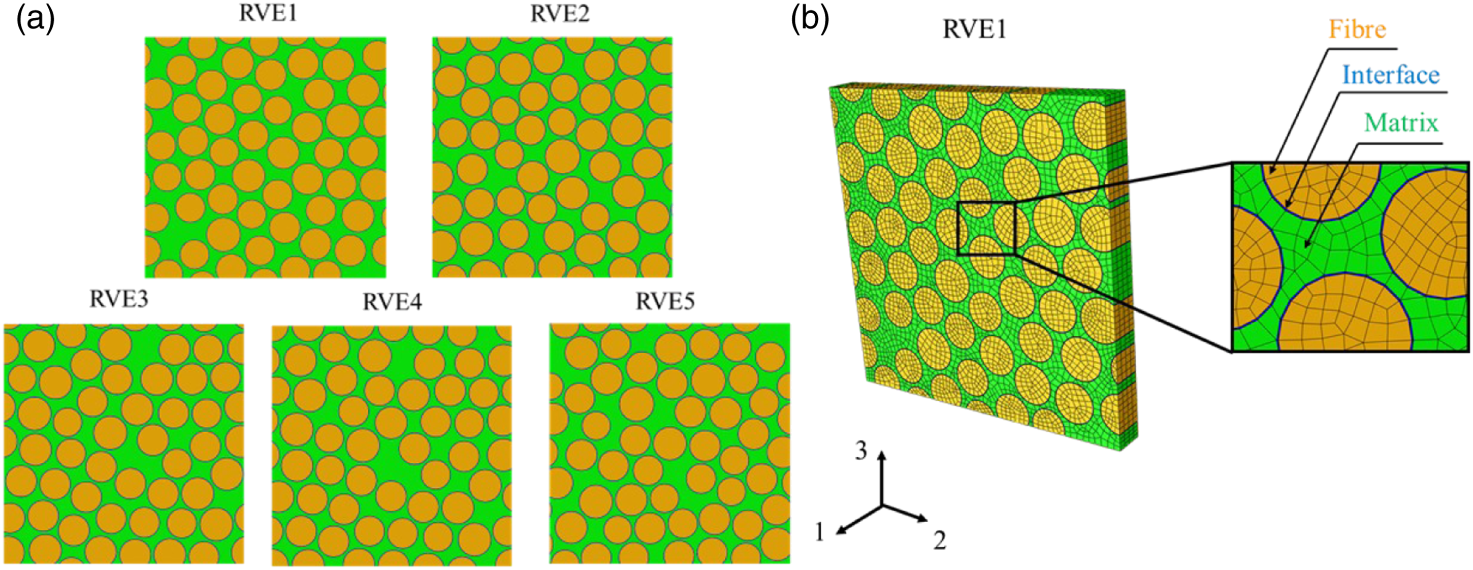
Constitutive models of constituents
Carbon fibres were modelled to be linearly elastic, brittle and transversely isotropic and were assumed not to contribute to the failure of the composite under transverse and shear dominated loadings. Previous work has shown that the hydrostatic stress has significant influences on the mechanical behaviour of the polymer,
29
and exhibits a completely different behaviour when subjected to various simple uniaxial loading conditions, such as brittle in tension while plastic in compression and shear.
30
Constitutive models, reported in the literature, to describe the mechanical behaviour of polymeric materials under multiaxial loading
31
include the extended Drucker-Prager (D-P) yield model, associated with a ductile damage criterion,
21
the modified Drucker-Prager plastic damage model,
19
and the elasto-plastic model with an isotropic damage constitutive model.
32
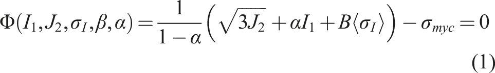
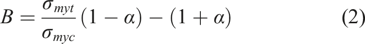
In this study, the polymer matrix was modelled as an isotropic elastoplastic solid. The modified Drucker-Prager plastic damage model
33
was used to model the mechanical behaviour of epoxy under multiaxial stress states. The yield surface of the epoxy is expressed by (a) Constitutive model of the epoxy matrix, (b) Constitutive model and damage variable D of fibre/matrix interface under pure shear load (black line) and combined compression and shear loads (blue line).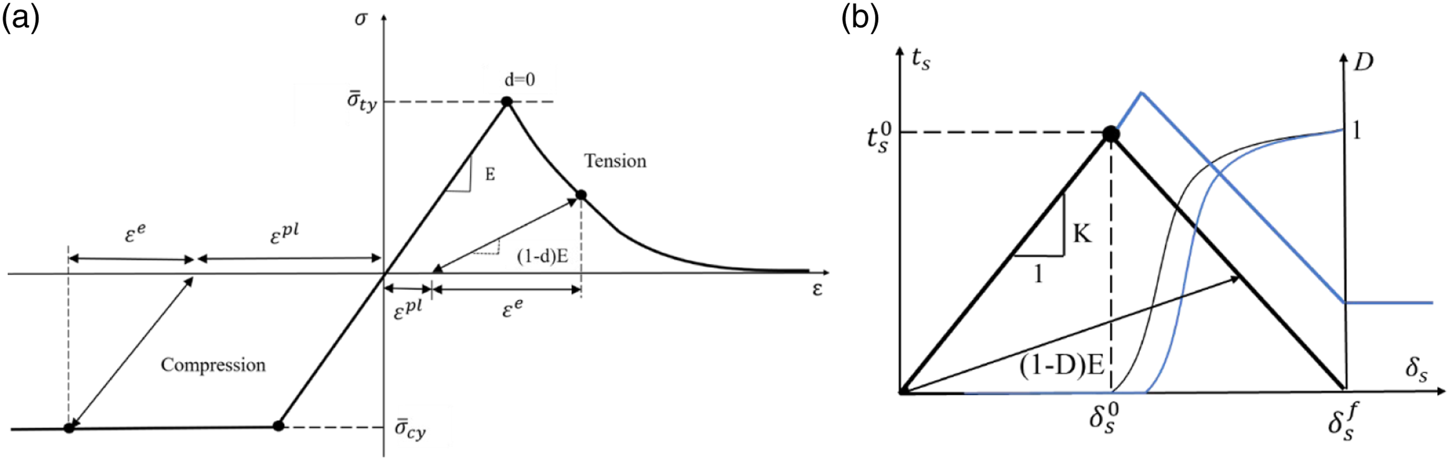
Material properties of the constituents. 26
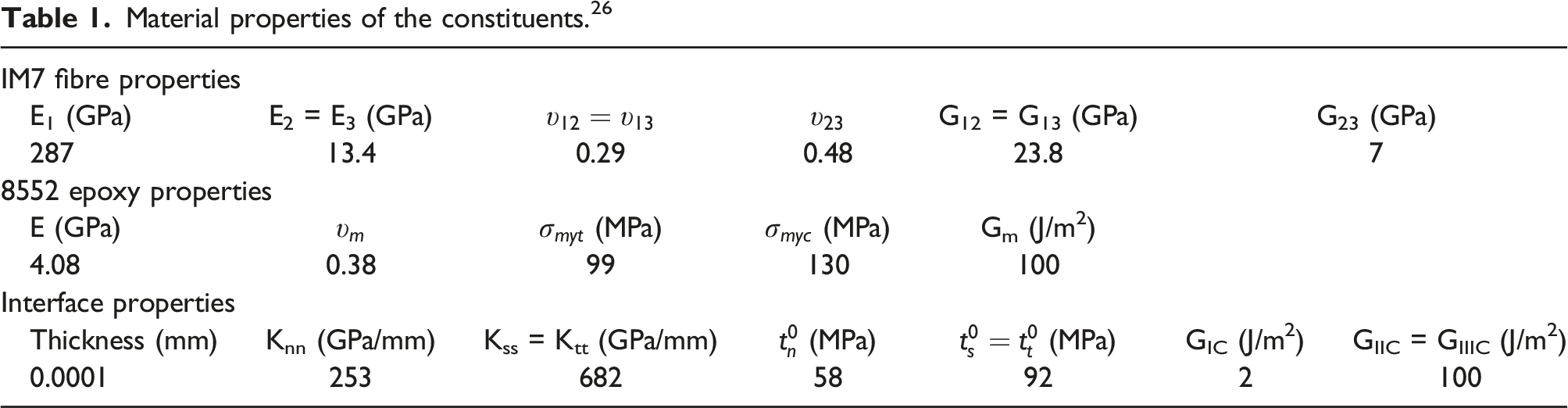
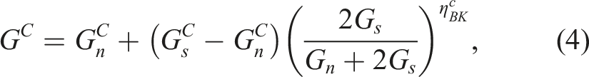
The calibrated interface strengths in normal and shear directions from our previous study 26 were 58 MPa and 92 MPa, respectively. These are in good agreement with the assumption that the interface normal strength is 2/3 of shear strength according to numerical 19 and experimental studies. 36 The interface fracture energy in mode I, G IC , could not be measured experimentally so it is usually assumed to be small and is in the range of 2–5 J/m2. 19 In this study, the fracture energy of 2 J/m2 in Mode I is adopted in the simulations, and due to the lack of experimental data, the interface fracture energy in shear is assumed to be equal to the matrix cracking fracture energy, 100 J/m2. 19 The friction between fibres and matrix after interface failure was considered and implemented in an ABAQUS/Explicit subroutine.27,37,38 Figure 2(b) shows the constitutive model of the interface under pure shear (black line) and combined compression and shear loads (blue line). The material properties can be found in Table 1.
Periodic boundary conditions and loading cases
Periodic boundary conditions (PBCs) are imposed on the corresponding surfaces of the RVE using linear equations between the periodic nodes at opposite faces to guarantee the periodicity of the displacement and traction. The detailed implementation of PBCs can be found in.
39
The strains were computed from the imposed displacement divided by the corresponding lengths, while the normal and shear stresses were computed from the resultant normal and tangential forces acting on the RVE faces divided by the cross-section area. Six loading conditions out of the full complement of 10 are necessary for the failure analysis under biaxial loading conditions due to the transverse isotropy in the cross-section of unidirectional composites. In a loading condition with two stress components, four quadrants are used to describe the biaxial stress space. The calculated stress ratios are based on the resultant stresses obtained from numerical simulations under biaxial loading conditions. It was assumed that the failure envelopes under most of biaxial loadings are polynomial curves, which need a minimum of three points. However, for the loading scenario of transverse compression and in-plane shear, where more complex failure mechanisms are involved (i.e. friction between fibre and matrix), more than five loading cases are required to capture representative failure modes and to provide enough data for the curve fitting of failure envelopes. Figure 3 shows the total number of biaxial loading conditions and an example of the stress ratio determination under combined transverse tension and in-plane shear. In Figure 3(a), the grid represents a biaxial loading condition, and the same colour in different grid locations represents an equivalent loading condition. Here two sets of loading conditions are grouped: transverse dominated loading conditions, including ( (a) Biaxial loading conditions, (b) An example of combined transverse tension and in-plane shear loading and (c) Stress curves in the (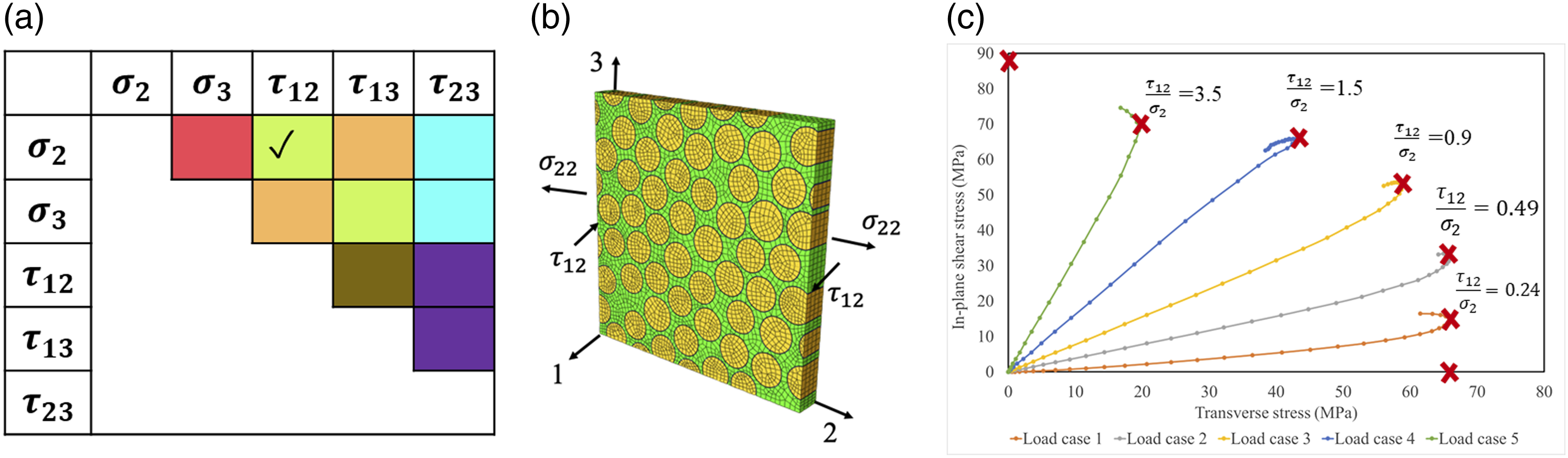
Determination of the transition point in biaxial loading cases
It is challenging to determine the transition point on the failure envelopes, especially when there is no obvious change on the curve. Two main strategies were used for the determination of the transition points. The first one is based on the change of the failure envelopes. The Puck theory, which is used to determine the transition point, takes two loading conditions into consideration, namely transverse compression and in-plane shear, transverse compression and out-of-plane shear. The failure envelopes obtained from both loading conditions have an obvious peak point, which is used for the determination of transition point. While for other loading conditions, which cannot be performed experimentally and have no corresponding theory for the prediction of transition points, the second strategy was used, which is based on the change of failure modes. For example, the failure mode under pure out-of-plane shear is interface debonding and matrix cracking, while under pure in-plane shear is matrix yielding. When these damage modes coexist in the RVE, the transition point is determined when there is no dominant or less obvious mode at final failure. It should be noted that the second strategy is microstructure-depdendant since failure modes with different microstructure could result in slightly different transition points.
Conventional failure theories
Tsai-Wu failure criterion
The Tsai-Wu failure criterion
5
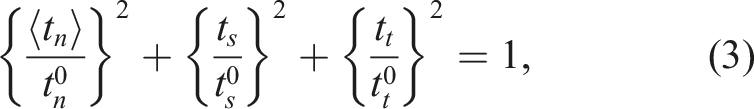
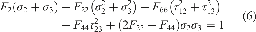
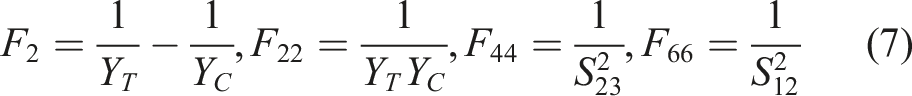
is a phenomenological interactive failure criterion for anisotropic composite materials. It is a highly interactive equation, which integrates all stress components in one equation. The general expression of the Tsai-Wu failure criterion is
Hashin failure criteria
Hashin proposed separate failure criteria for fibre and matrix by assuming a quadratic interaction between the tractions on the failure plane. These criteria can distinguish the failure of fibre and matrix in tension and compression 7 :
Matrix tension 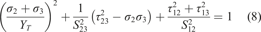
Matrix compression 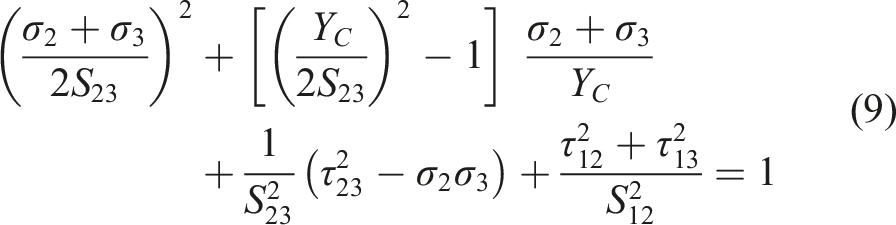
Computational results and discussions
Transverse dominated loadings
Failure envelope comparison
Figure 4 presents the comparison between the numerical results of the UD composite and Tsai-Wu and Hashin failure criteria under biaxial transverse dominated loadings. It can be found in Figure 4(a) (orange square box) that both Tsai-Wu and Hashin failure criteria underestimate the failure strength of the composite under biaxial transverse and out-of-plane tension loadings. Failure strengths predicted by Tsai-Wu and Hashin failure criteria agree with numerical results from the loading case where the stress ratio is −0.28. The comparison suggests that the predicted envelope from the Hashin criterion agrees well with the fitted envelope from numerical failure points to the infinite strength. Due to its closed envelope, the prediction from the Tsai-Wu criterion only agrees with the fitted envelope until the loading condition with a stress ratio of 3.13. It is still an open question whether the failure surface should be open or closed, especially under hydrostatic pressure.
13
According to the numerical results, the fitted envelope under transverse compression and out-of-plane compression is open since the matrix suffers from hydrostatic pressure due to the biaxial compressive loads and constraints from fibres, resulting in a higher failure strength of the matrix. The comparison between the numerical results and the failure envelopes predicted by the conventional failure criteria under biaxial transverse compression and out-of-plane shear (see Figure 4(b)) shows excellent agreement. However, both failure criteria overestimate the failure strengths when transverse tension was involved. This is mainly because under the transverse tension and out-of-plane shear loadings, the interface failure dominates which is not considered in these conventional failure criteria. Figure 4(c) shows the comparison between the experimental results,
41
numerical results and failure envelopes predicted by the failure criteria under combined transverse and in-plane shear loadings ( Comparison between failure envelopes of unidirectional composites fitted from numerical failure points, Tsai-Wu and Hashin failure criteria under transverse dominated loadings: (a) transverse and transverse stresses, (b) transverse and out-of-plane shear stresses, (c) transverse and in-plane shear stresses (same loading plane) and (d) transverse and in-plane shear stresses (different loading plane).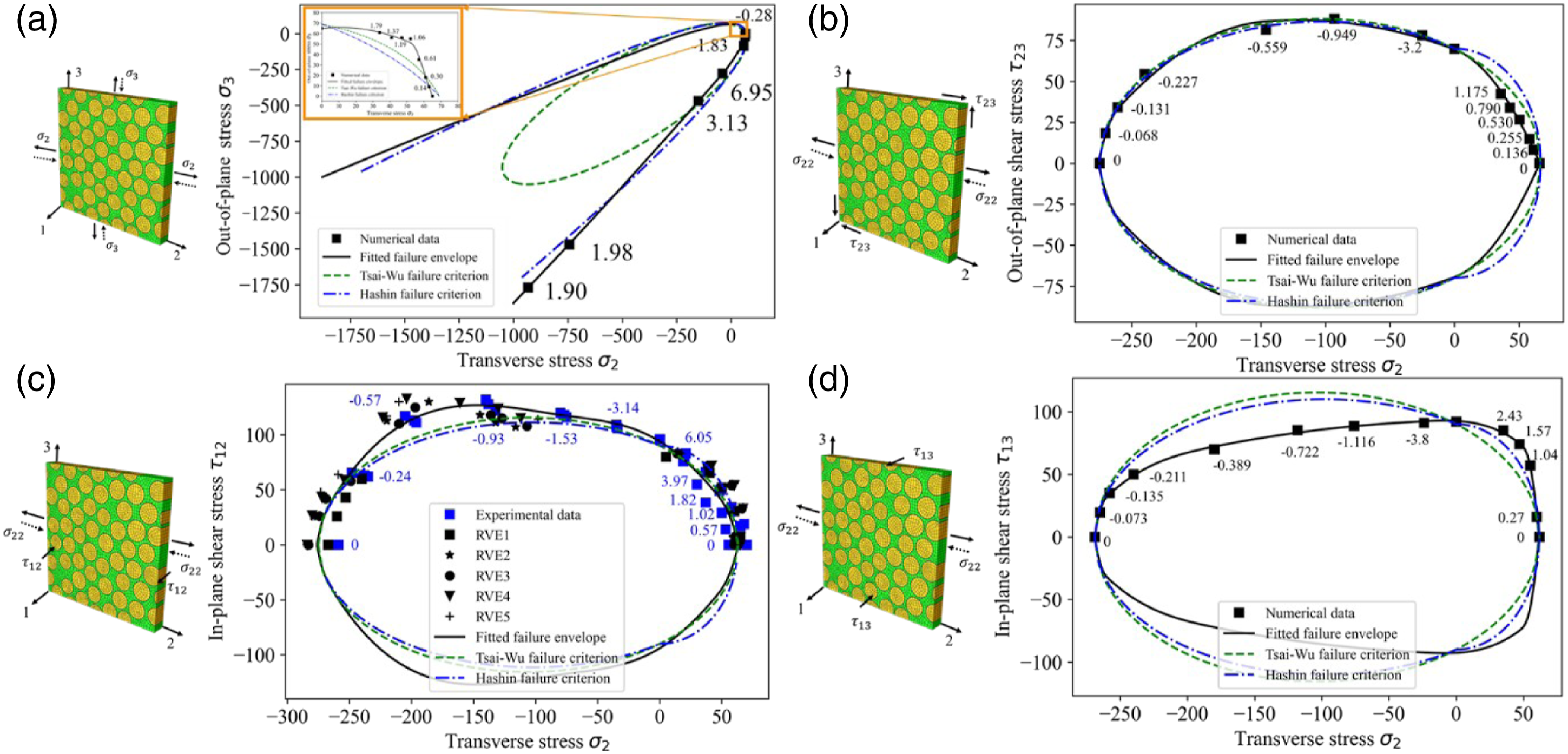
Failure modes
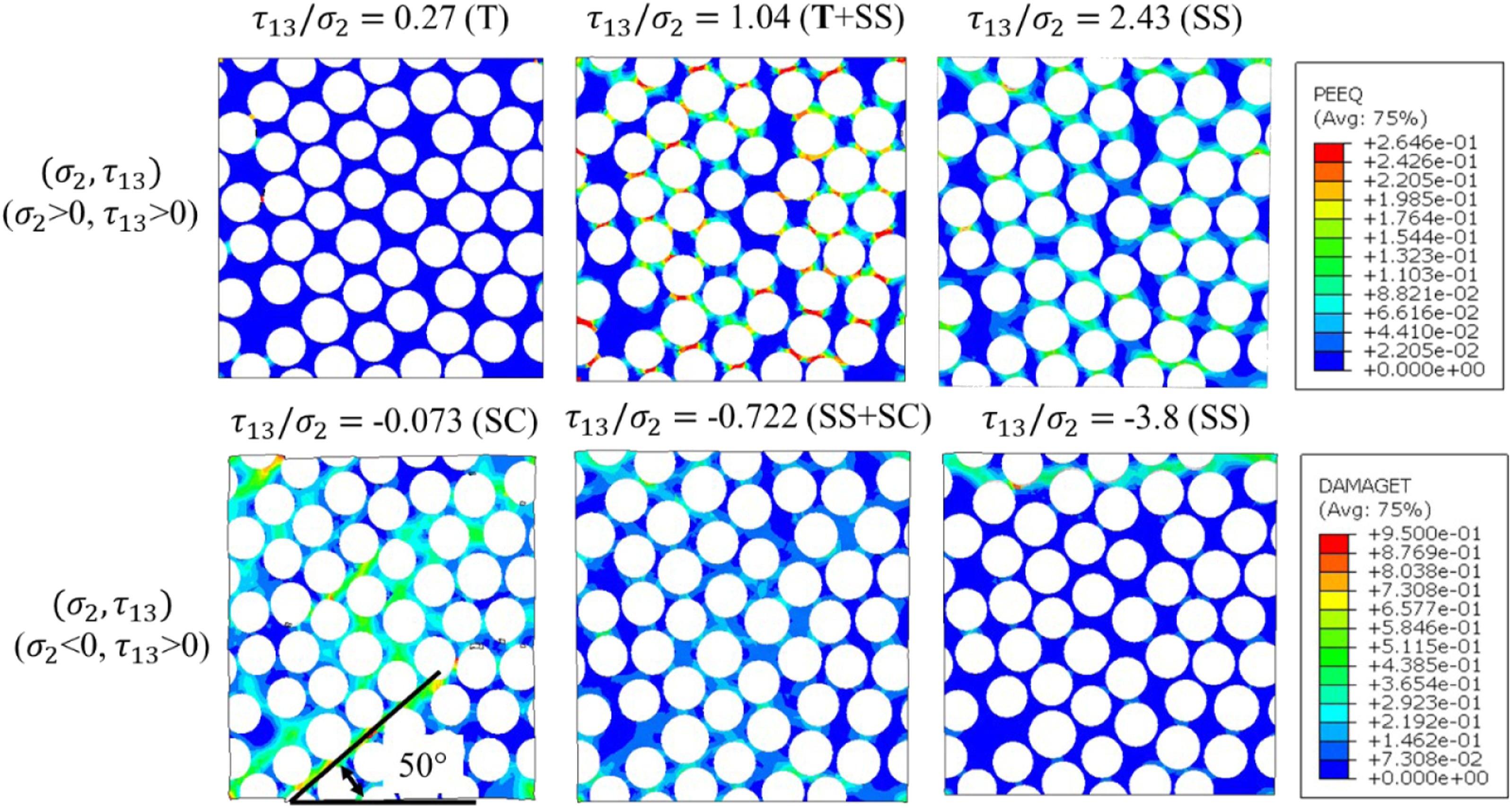
Figure 5 shows the comparison of failure modes obtained from different stress ratios under biaxial transverse and out-of-plane tensile/compressive loadings. These stress ratios correspond to the ones labelled in Figure 4(a). It can be found that in the loading of ( Failure modes of the IM7/8552 composite under biaxial transverse and out-of-plane tensile/compressive loadings. (For interpretation purposes, The matrix tensile failure ‘T’ and shear failure ‘SC’ are characterised by the damage variables DAMAGET and PEEQ, respectively. ‘No’ means no failure found in the loading case).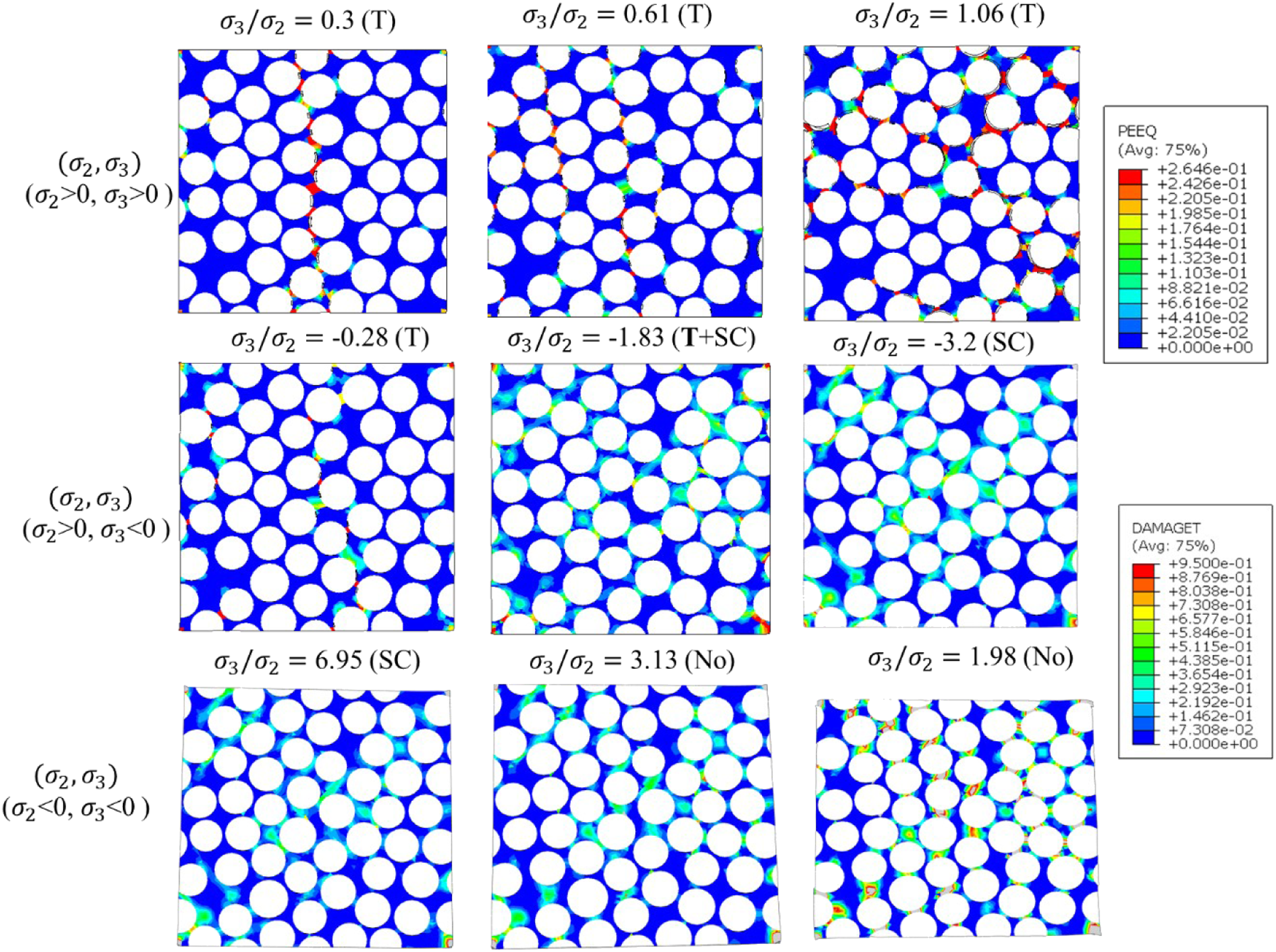
Figure 6 shows the comparison of failure modes obtained from different stress ratios under biaxial transverse tension/compression and out-of-plane shear loadings, and these stress ratios correspond to the ones labelled in Figure 4(b). Under biaxial transverse tension and out-of-plane shear, due to the smaller normal strength of the fibre/matrix interface compared to the tensile strength of the matrix, interface debonding occurs first, followed by matrix cracking. Both damages join together to form a fracture plane either perpendicular to the transverse direction (for transverse tension-dominated loadings) or inclined at an angle of 40° for out-of-plane shear-dominated loadings. Since there is no failure mode transition for this loading case, no transition point can be obtained. For the sake of the discussion on the progressive failure at different stress ratios, three ratios were still used. At the stress ratio Failure modes of the IM7/8552 composite under combined transverse and out-of-plane shear. (For interpretation purposes, The matrix tensile failure ‘T’ and shear failure ‘SC’ are characterised by the damage variables DAMAGET and PEEQ, respectively).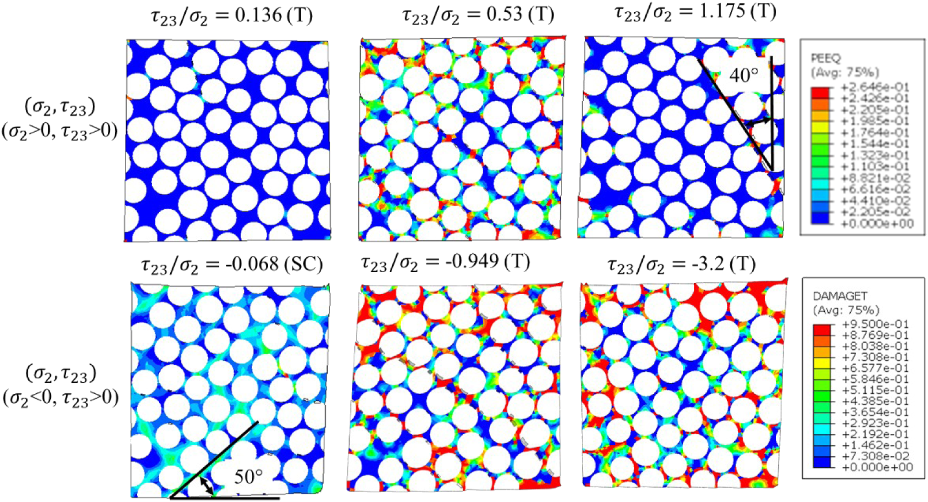
Figures 7 and 8 show the comparison of failure modes obtained from different stress ratios under biaxial transverse and in-plane shear loadings. These stress ratios correspond to the ones labelled in Figures 4(c) and (d), respectively. Similar failure modes can be found under ( Failure modes of the IM7/8552 composite under combined transverse and in-plane shear loadings ( Failure modes of the IM7/8552 composite under combined transverse and in-plane shear loadings 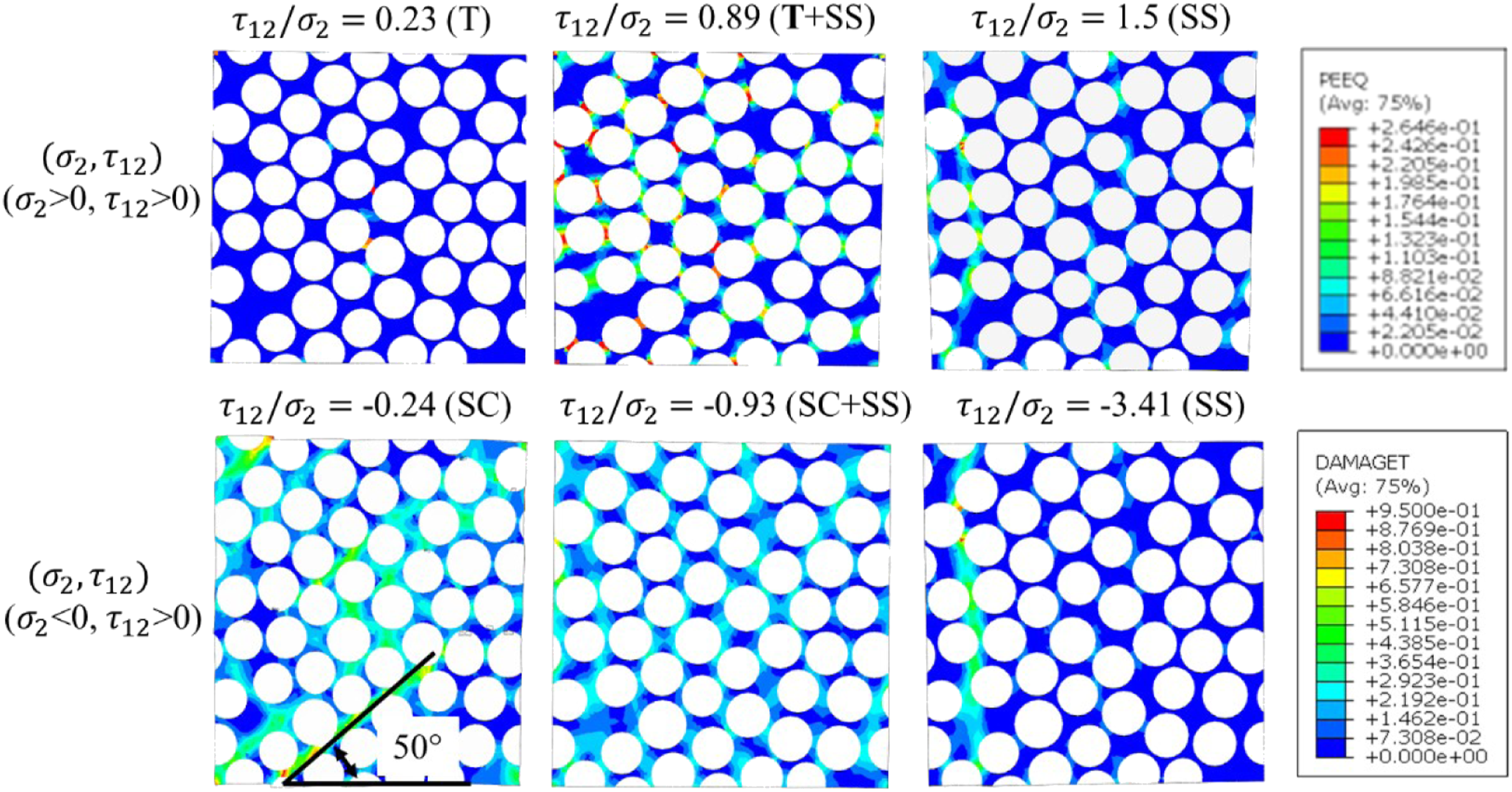
Shear dominated loadings
Failure envelope comparison
Figure 9 compares the numerical results and the failure envelopes plotted from conventional Hashin and Tsai-Wu failure criteria. The red squares in Figure 9 represent the numerical data for curve-fitting reasons, in which a negative Comparison between failure envelopes of unidirectional composites from fitted numerical failure points, Tsai-Wu and Hashin failure criteria under shear-dominated loadings: (a) in-plane shear and in-plane shear stresses, (b) in-plane shear and out-of-plane shear stresses.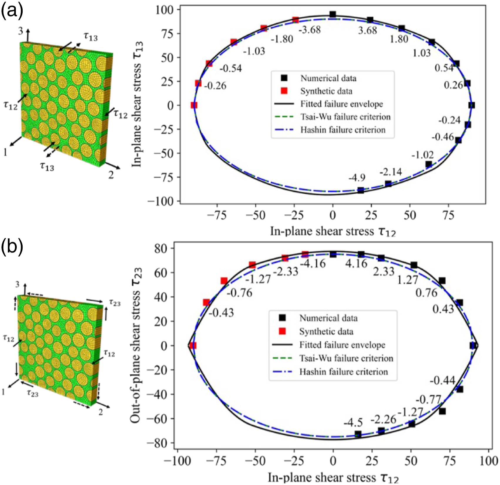
Failure modes
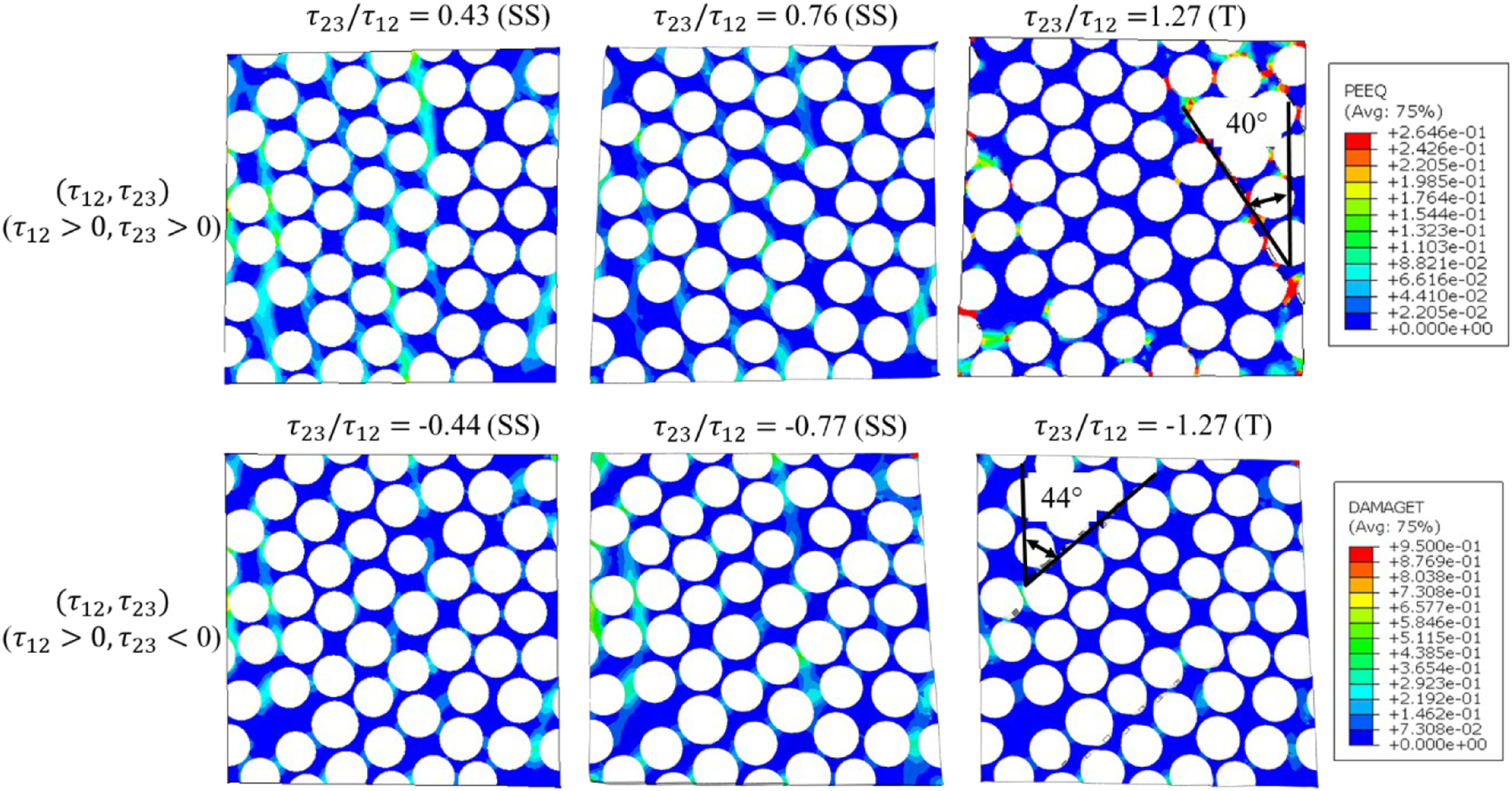
Figure 10 shows the comparison of failure modes of the UD composite under biaxial in-plane shear loadings with different directions. It can be found that when the shear stresses are in the same direction and similar, only one main shear plane with an inclination angle of 45° is formed, while two or more shear planes with angles less than 45° are formed when either shear stress is larger than the other. However, several shear planes are formed when the shear stresses are in the opposite direction and similar. The number of planes decreases when either shear stress is larger than the other and two main planes with an inclination angle of 45° can be observed. Figure 11 shows the comparison of failure modes under biaxial in-plane and out-of-plane shear loadings with different directions. The same failure modes and a similar trend of shear bands can be found in both loading conditions. The difference in the fracture angle in both out-of-plane stresses dominated loadings probably comes from the microstructure of the cross-section in composites, which changes the direction of the fracture propagation. Failure modes of the IM7/8552 composite under biaxial in-plane shear loadings ( Failure modes of the IM7/8552 composite under biaxial in-plane and out-of-plane shear loadings (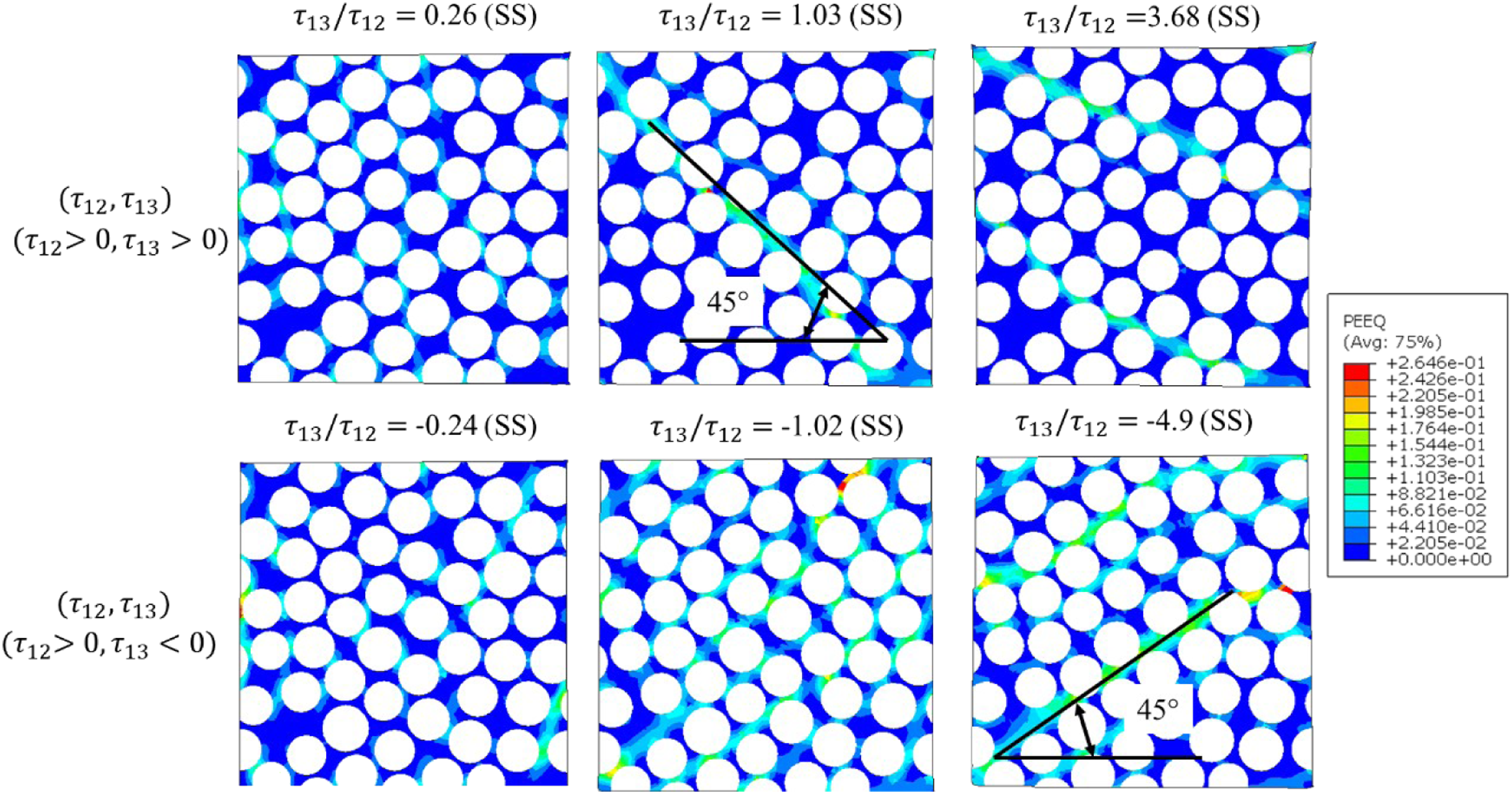
Transition point determination under biaxial loading conditions
Stress ratio of transition points of UD IM7/8552 composites under biaxial loadings.
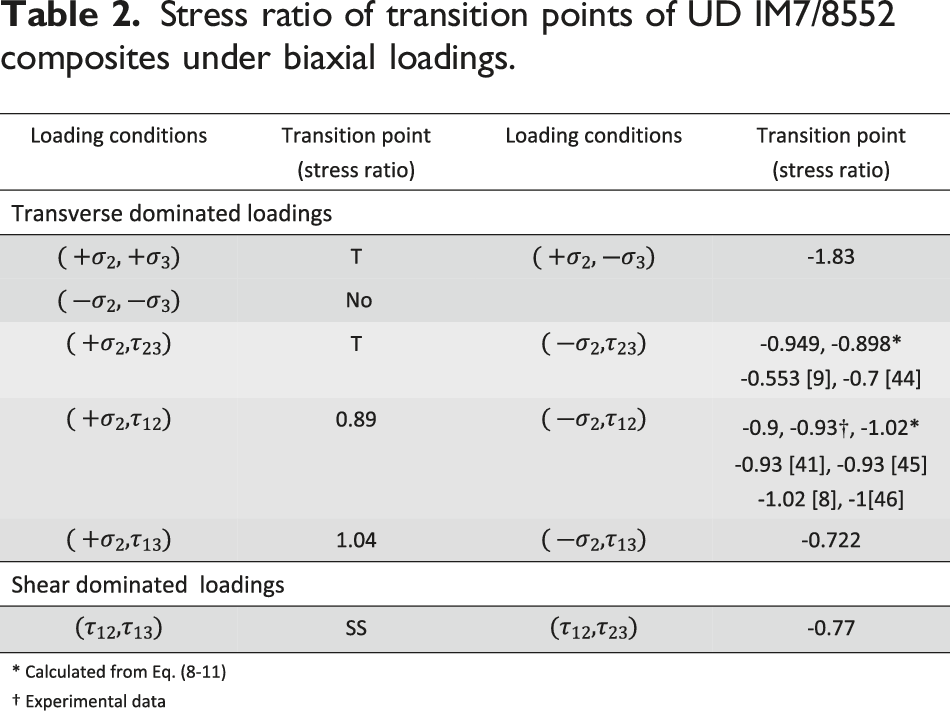
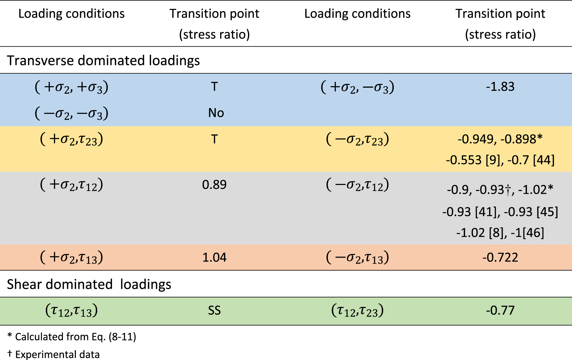
In the transverse dominated biaxial loadings, since the failure modes of the composite are interface and matrix tensile failure under transverse tension and out-of-plane tension/shear loads, there is no failure mode transition point in such biaxial loadings. While under combined transverse tension and out-of-plane compression loads, only matrix shear failure under compression was found and no failure was found under biaxial transverse and out-of-plane compression. Under transverse compression and out-of-plane shear, good agreement in the stress ratio of transition points is found between the one obtained from the IM7/8552 composites and glass FRP composites.9,43 Off-axial tests have been conducted on different material systems to determine the failure strengths under biaxial loadings, such as4/3501–6,
44
IM7/8552
8
and E-glass/RP528.
45
An excellent agreement can be found between experimental results, even across different material systems. In the biaxial in-plane shear loadings, only matrix shear failure due to shear stress is found thus no transition point is detected, while in the combined in-plane shear and out-of-plane shear loadings, the stress ratio (
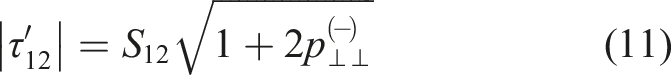
Based on Puck’s theory,
6
the corresponding values at transition points under combined transverse and in-plane shear, and transverse and out-of-plane shear loadings can be calculated for comparison with numerical and experimental results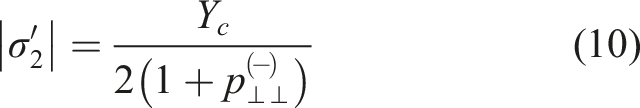
Conclusion
This study introduced a 3D high-fidelity micromechanics-based RVE model with random fibre distributions to predict the inter-fibre failure envelopes and failure modes of IM7/8552 UD CFRP composite laminae under biaxial loadings. The RVE model was built with three constituents, namely the fibre, matrix and fibre/matrix interface. Fibres were modelled to be transversely isotropic and elastic; the interface was modelled with a cohesive zone model with the consideration of friction via a subroutine; the matrix was modelled by a Drucker-Prager plastic damage model. Only six out of the 10 possible biaxial stress combinations were taken into account due to the transversely isotropic characteristics of the cross-section and symmetry of shear stresses. Periodic boundary conditions were utilised for the application of biaxial loadings. The novelty of the current study lies in the use of (i) high-fidelity 3D micromechanics-based finite element modelling to assess failure criteria and (ii) the determination of transition points and progressive inter-fibre failure analysis of UD composties, under various possible biaxial loading conditions, some of which are not easy to determine experimentally.
Comprehensive biaxial inter-fibre failure analysis of UD IM7/8552 composites and the comparison of failure envelopes obtained from computational analysis and classical failure criteria (Tsai-Wu and Hashin) were conducted considering the failure mode transition. The main findings and conclusions are given below: • Both failure criteria agree well with the computational results in • Both failure criteria agree well with the computational results for shear-dominated loadings. The difference between the results obtained from • The stress ratio at the transition points describes the failure transition mechanisms which could be taken into account in the failure criteria for better prediction of composite failure under biaxial loading conditions.
These virtual tests can provide full control of the composite microstructural and material properties, allowing the optimisation and exploration of the microstructure in the improvement of the mechanical performance of composites. Also, this work suggests a need to improve existing mesoscale failure criteria that only rely on ply properties.4,6 Some important microstructural parameters and/or information are suggested to be taken into account in the existing or newly proposed failure criteria, such as fibre/matrix interfacial debonding,21,24 fibre/matrix friction 19 and failure transition points.1,8 Furthermore, 3D high-fidelity RVE modelling of composites under longitudinal loadings is under investigation, which considers fibre kinking and stochastic fibre strength phenomena. The failure points obtained from these simulations can be used to construct fibre dominated failure criteria.
Footnotes
Declaration of conflicting interests
The author(s) declared no potential conflicts of interest with respect to the research, authorship, and/or publication of this article.
Funding
The author(s) disclosed receipt of the following financial support for the research, authorship, and/or publication of this article: This study was conducted as part of the Belfast Maritime Consortium UKRI Strength in Places project, “Decarbonisation of Maritime Transportation: A return to Commercial Sailing” led by artemis Technologies, Project no. 107138.