
Abstract
In this work, three-dimensional (3D) finite element simulations were undertaken to study the effects of lightning strikes on the microscale behaviour of continuous fibre-reinforced composite materials and to predict and understand complex lightning damage mechanisms. This approach is different from the conventional mesoscale or macroscale level of analysis, that predicts the overall lightning damage in composite laminates, thus providing better understanding of lightning-induced thermo-mechanical damage at a fundamental level. Micromechanical representative volume element (RVE) models of a UD composite laminate were created with circular carbon fibres randomly distributed in an epoxy matrix. The effects of various grounding conditions (one-, two-, and four-side grounding), fibre volume fractions (V f = 55, 60%, and 65%), and peak current amplitudes (10, 20, and 40 kA) on microscopic damage in RVE models were characterised to understand fibre, epoxy matrix, and fibre-matrix interfacial damage associated with a lightning strike. Thermal damage, estimated based on epoxy matrix decomposition temperature, was largely constant up to 20 kA before increasing significantly at 40 kA. Severe thermal damage steadily decreased with increasing V f . Thermo-mechanical damage was predicted using a ductile plasticity model with Drucker–Prager yield criterion for epoxy matrix failure, and cohesive surfaces for fibre-matrix interface debonding. Thermal strain had the largest contribution to thermo-mechanical damage, while dynamic pressure loading was negligible in all RVE models. The RVE model proposed in this work, to the best of the authors’ knowledge, is the first model predicting lightning-induced fibre-matrix interfacial damage.
Keywords
Introduction
Lightning strikes present a potential risk to the structural integrity of composite materials, particularly those used in primary aircraft structures. Lightning strikes produce both direct effect damage (physical damage near the lightning attachment) and in-direct effects (appreciable, non-structural damage associated with coupling with on-board electronics) on aircraft composites. Lightning direct damage is caused by a combination of various thermal and mechanical loading, i.e., Joule heating emanating from lightning current flow, direct plasma heat fluxes impinging the lightning attachment location, and dynamic mechanical loading.1,2 Therefore, research into lightning strike damage and protection systems, has been increasing for many years and has followed parallel experimental and simulation pathways.3–12
Experimental research has been conducted with the primary focus on idealised standard lightning waveforms with ≥100 kA peak current amplitudes, named Waveforms A or D13–15 since these waveforms produce ample electrical current, which is instantaneously dissipated as heat (i.e., thermal damage). Direct lightning damage in typical carbon fibre-reinforced polymer (CFRP) composites includes a number of significant damage modes including fibre damage (i.e., fray, fracture, or blow-out), matrix damage (i.e., cracking or thermal decomposition), delamination, and through-thickness damage penetration. 16
Modelling of lightning strikes has typically fallen into two categories focussing on either (i) the external plasma conditions at the lightning attachment point, due to rapid ionisation of the high temperature and high pressure air in the arc channel17–20 or (ii) the composite material internal damage mechanisms divided into three broad areas; thermal-electric,5,7,16,19,21 mechanical pressure loading10,22–24 and thermal expansion25,26 analyses. The majority of this work, presented in open literature, has been conducted at the mesoscale level, where each composite ply is modelled as a homogenous medium (thus, no damage characteristics of each constitute) and inter-laminar interactions are considered between plies using gap conductance or cohesive zone models. These models have almost exclusively used a simulated specimen measuring 150 mm × 100 mm5,16,19,21,27 and a specimen layup of [45/0/-45/90]4s,16,21,27–29 as inspired by the pioneering work of Hirano et al. 13
Sun et al. 30 recently studied the lightning‐induced conduction characteristics of CFRP composites. The authors suggested that at lower electric field strength (the intensity of an electric field at a particular location) electrons cannot overcome the interfacial barrier in the “fibre‐resin-fibre” unit and are therefore not involved in the conduction process. Rather, the low‐amplitude direct current (DC) or alternating current (AC) conduction paths are controlled only by the contact of neighbouring fibres. However, for higher intensity current loading (50–1500 A), contact between neighbouring fibres was not sufficient and therefore mixed conduction paths “fibre–fibre” and “fibre‐resin‐fibre” both contribute to current flow. The authors used their findings and assumptions to inform mesoscale modelling of resulting lightning strike damage. While this approach could inform mesoscale modelling, representative volume element (RVE)-based microscale modelling can characterise unique damage mechanisms of each constitute and better illuminate the current flow through and along constitutes under realistic lightning strike loading.
Representative volume element modelling
The RVE method, using a small representative volume to represent the whole material, is widely applied to characterize the macroscopic response of composites and primarily used for effective property calculation. RVE modelling has been widely used in the study of two-dimensional (2D) and three-dimensional (3D) woven composites31–35 and also in multi-scale modelling of unidirectional (UD) composites.36–41 Totry et al. 42 used a 2D RVE model to predict the failure of a composite laminate under transverse compression and out‐of‐plane shear loading, while Sun et al. 43 used a 3D RVE model to predict the failure of a composite laminate under combined transverse compression and out‐of‐plane/in‐plane shear bi-axial loading. Several studies have typically used RVE modelling to obtain effective material properties from a representative unit cell. Chen et al. 44 proposed a 3D RVE micromechanical model to capture the coupled effects of fibres, matrix, and fibre-matrix interface on failure under different multiaxial loading conditions. The authors used an RVE model (fibre diameter d f = 7 μm and fibre volume fraction V f = 60%) measuring 50 μm × 50 μm × 10 μm. The interface thickness was identified using an artificial neural network (ANN) and interface properties were taken from literature. González and Llorca 45 modelled the mechanical behaviour of UD carbon or glass fibre polymer-matrix composites. A square RVE model (d f = 10 μm and V f = 50%) was used with randomly distributed parallel fibres created using a modified random sequential adsorption (RSA) algorithm.
RVE modelling has been limited within the field of lightning strike research. Guo et al. 46 and Karch et al. 23 both proposed RVE-based micromechanics models to estimate the effective properties of expanded metal foils, the most common lightning strike protection (LSP) layers. In the work done by Guo et al., 46 the RVE models consisted of a 6 × 6 unit-cell, where one unit was a single grid in the long width of the diamond (LWD) and short width of the diamond (SWD) directions. The effective electrical conductivities were calculated to evaluate the lightning shielding performance of expanded foils subjected to 100 kA Waveform D. Karch et al. 23 used similar RVE models, but with periodic boundary conditions (PBCs), to conduct a microstructural homogenisation to determine the effective mechanical properties of an expanded foil LSP layer. More recently, Wang et al. 47 developed RVE models to calculate material properties of NCF/CIPCF film using a RSA algorithm. Chippendale and Golosnoy 48 used an RVE model to determine the effect of percolation phenomena and the percolation threshold on the bulk electrical conductivity of CFRP.
Background summary and paper aim
In summary, all existing lightning strike simulation research has largely focussed on a singular modelling strategy - homogenised mesoscale modelling to predict the overall lightning damage in composite laminates in the presence or absence of an outer LSP layer. However, this modelling approach is not capable of capturing unique damage mechanisms of each constitute (i.e., matrix and carbon fibre). Instead, RVE-based micromechanics models can be developed to understand lightning damage mechanisms at a smaller length scale. As previously mentioned, a few RVE studies were performed within the field of lightning strike research but were limited to the calculation of effective properties for composite plies and LSP layers. Understanding lightning-induced damage in composites at a microscale level is still lacking. It is still not known how each constitute is damaged due to lighting or what the dominant damage mechanisms are. In addition, it is not known how lightning waveform properties (i.e., peak current) influence these damage mechanisms or where the weakest (critical) location for damage initiation is. Therefore, the motivation of the current study is to address these unknowns.
This paper proposes, for the first time, micromechanics-based 3D RVE models to characterize the progressive failure of CFRP composites under thermal, mechanical, and coupled thermo-mechanical loading, consistent with actual lightning direct effects. Microscopic fibre damage, matrix damage, and fibre-matrix interface failure were predicted from the RVE models, consisting of randomly distributed carbon fibres in an epoxy matrix. Various electric potential boundary conditions were imposed to understand the effects of grounding on microscopic thermal damage in RVE models. The effects of fibre volume fraction and peak current amplitude on microscopic damage evolution were also thoroughly studied. In this work, the matrix failure was predicted using a ductile plasticity model with Drucker–Prager (DP) yield criterion, and the fibre-matrix interface debonding was characterized using cohesive surfaces with a bilinear traction-separation law. This work has attempted to propose an efficient and robust modelling framework to understand localised damage in CFRP composites caused by lightning, at the microscale level. This work is fundamentally different from the typical mesoscale modelling used to predict the overall lightning damage in composite laminates. Rather, this work focusses on predicting the microscopic lightning damage to understand complex lightning damage mechanisms near the lightning attachment.
Methodology
Representative volume element modelling
The 3D RVE model of a UD composite laminate included parallel, circular cross-sectioned carbon fibres randomly distributed in an epoxy matrix. The RVE models with three fibre volume fractions (V
f
= 55%, 60%, and 65%) were developed with a total volume of 50 μm × 50 μm × 50 μm. Fibres had diameters of 5.3–7 μm and were randomly generated and positioned such that the distance between neighbouring fibres was ≥0.035d
f
, in line with Ref. 45, to ensure an adequate discretisation of this region. A periodic microstructure was maintained by splitting those fibres which intersected the RVE boundary and copying the overlapping portion of the fibre to the opposite side or corner of the RVE model, in line with Refs. 44,45. Note that a periodic microstructure differs from PBC connecting two opposite RVE edges by constraints. The resulting RVE models are shown in Figure 1. No designated interface region was modelled in the RVE models. Rather, cohesive surfaces were applied at fibre-matrix interfaces to understand interfacial debonding. Representative RVE models with Vf = 55%, 60%, and 65%.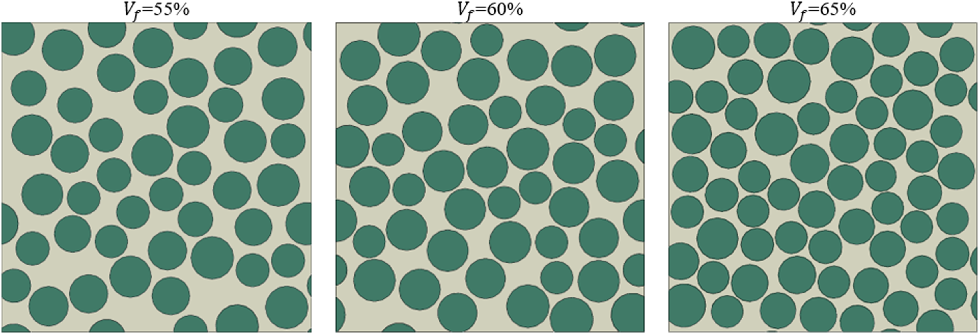
Modelling of lightning strike effects on the RVE model was completed in two stages. The first stage was a thermal-electric model predicting the temperature distribution in the RVE model primarily due to Joule heating. The second step predicted mechanical damage resulting from temperature, thermal expansion and/or pressure loading. This two-step sequential modeling procedure enables the thermal and mechanical damage to be decoupled from the total (combined) lightning damage in the RVE model. However, it also allows temperature, thermal expansion and pressure loading to be applied together.
To study both the thermal and mechanical damage within the RVE models, there was a need to assemble an appropriate set of simulation methods based on existing literature to predict damage with different boundary and loading conditions. Therefore, an analysis workflow was assembled for the work herein, as outlined in Figure 2, which was adapted from Refs. 26,49,50. The time-dependant temperature profile predicted in a thermal-electrical model was transferred to a thermo-mechanical model using python scripts and the method developed by Millen et al.,26,49,50 in which a temperature profile is recorded and transferred for each node from one model to the next. This approach allowed the electro-thermal coupling effect to be replicated within the thermo-mechanical RVE simulation through the transfer of the temperature profile. Thus, the temperature prediction of each thermal-electric simulation was passed to an equivalent thermo-mechanical simulation. Therefore, the time dependent variation in temperature is represented throughout the duration of the thermo-mechanical RVE simulation when predicting specimen damage. Subsequently, two sequential simulations could be completed for each RVE model with time periods of 30 μs for both analyses. Both model types will be now discussed in more detail. Simulation flowchart.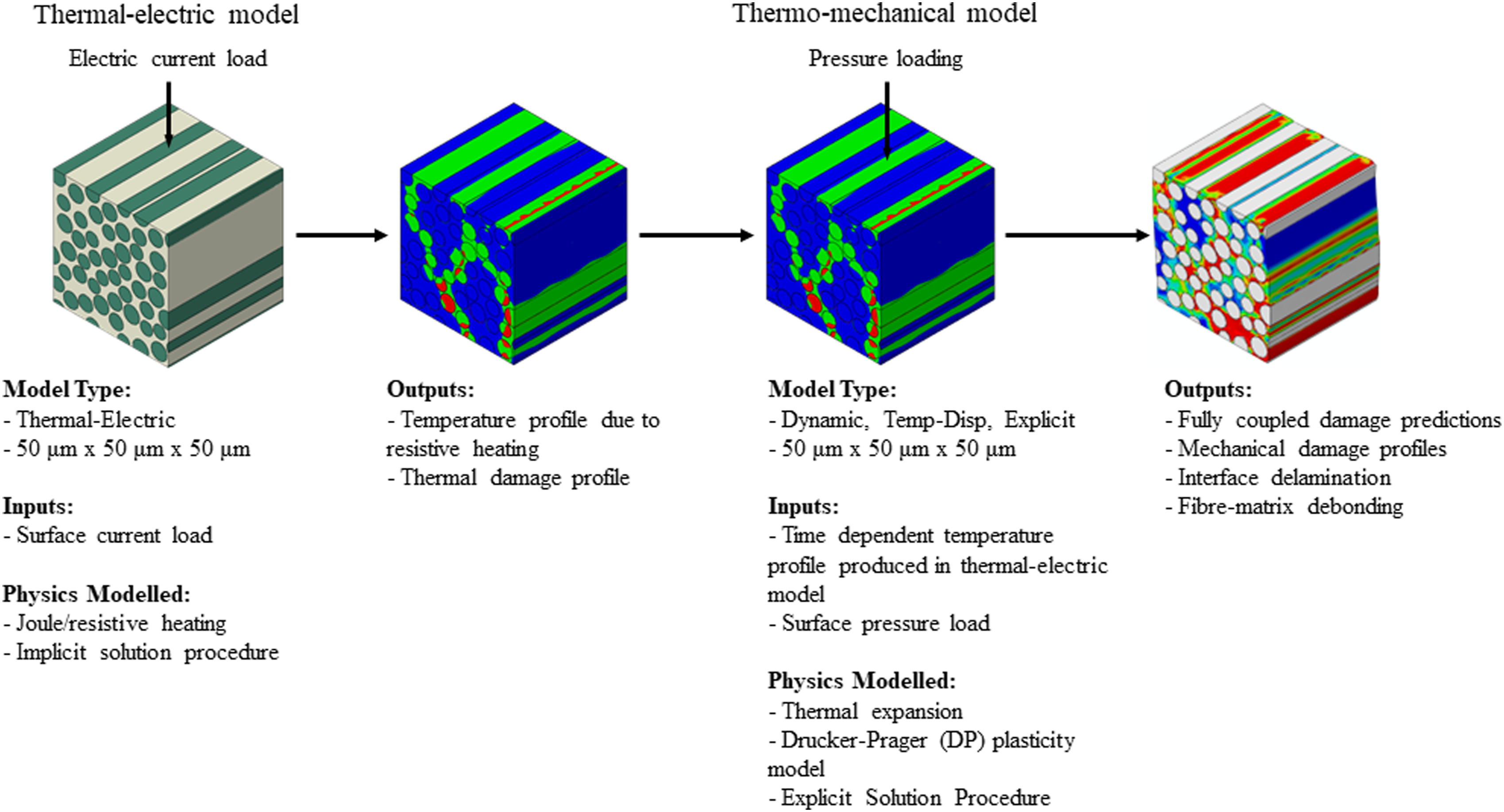
Thermal-electric representative volume element model
In the thermal-electric model, electric current loading was applied to the top surface of the RVE shown in Figure 3(a). The arc radius was assumed to be constant given the very small size of the RVE model. Therefore, electrical loading (i.e., surface current) was applied uniformly to the entire top surface. Zero electrical potential boundary conditions, representing the grounding terminal, were imposed on the bottom surface of the baseline RVE model (Figure 3(a)). PBC were not considered in this work. Note that PBC are typically used to calculate the effective properties of a RVE model and avoid potential issues associated with boundary effects. This work intends for microscopic characterisation of lightning-induced damage in a RVE model, thus PBC are not required. While the recommended Waveform A is 200 kA (T1/T2 = 6.4/69 µs),
51
the typical laboratory and simulation lightning test Waveform A (T1/T2 = 4/20 µs)13,51 with three peak current amplitudes of 10 kA, 20 kA and 40 kA and a time period of 30 µs was applied to each RVE model, as shown in Figure 3(b).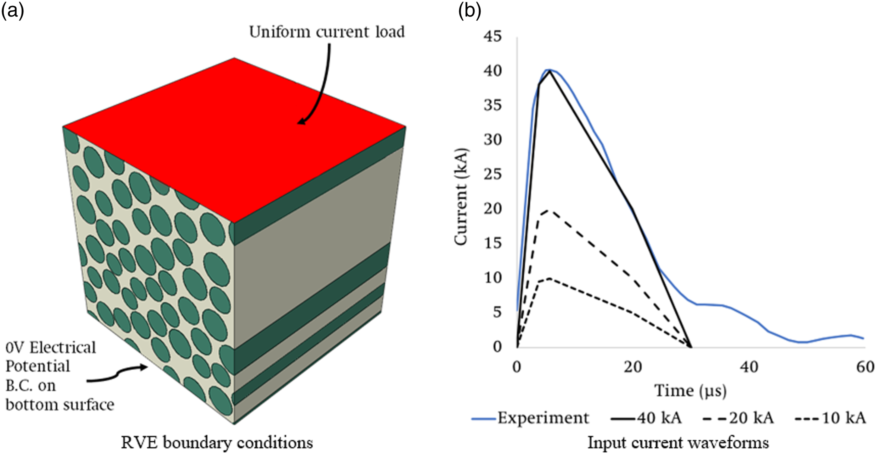
Electrical current flow strongly depends on both the optimal conduction path and grounding conditions, i.e., current preferentially flows through the least resistance path in a material to the grounding terminal. Thus, careful consideration of electrical potential was made in this work. In addition to the baseline RVE model (Figure 3(a)), additional parametric studies were performed to study the effects of grounding conditions on microscopic lightning thermal damage in RVE models (V
f
= 55%) subjected to 40 kA peak current load. Three different sets of ground boundary conditions were considered herein and are shown in Figure 4, including (i) bottom surface only, (ii) bottom surface and two side surfaces (where two side surfaces corresponds to the surfaces parallel to the fibre direction), and (iii) bottom surface and four side surfaces. Grounding conditions used in thermal-electric representative volume element models.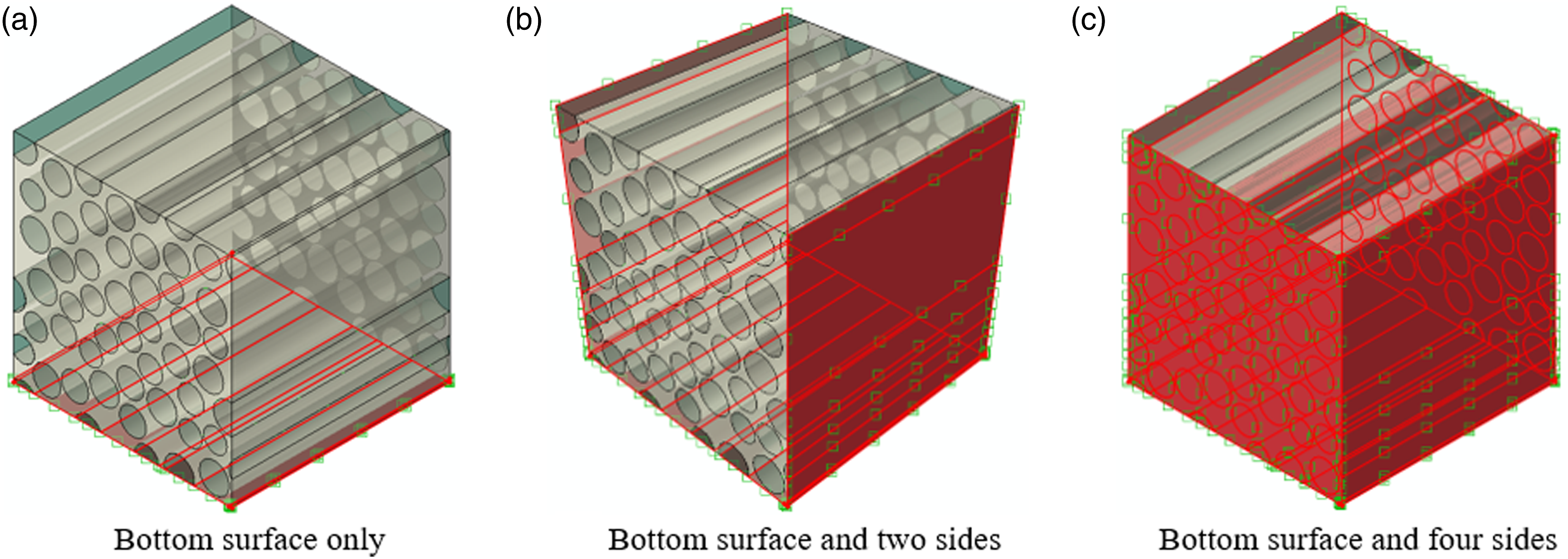
Thermal-electric material properties.
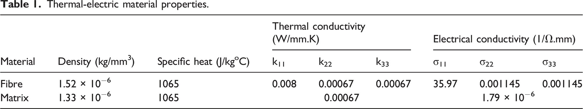
In Table 1 the 1-direction is the fibre axial direction, while the 2- and 3-directions correspond the radial direction.
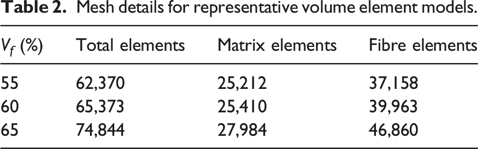
Mesh details for representative volume element models.
Thermo-mechanical model
Thermo-mechanical analysis was completed with a dynamic, temperature-displacement, explicit analysis step in ABAQUS/Explicit using 3D trilinear displacement and temperature, reduced integration elements, with hourglass control (C3D8RT).
Pressure loading was applied to the same specimen surface as the current load previously. To determine the equivalent mechanical (shockwave) loading from the peak current waveform a conversion procedure was required. In practice, the magnitude of mechanical loading associated with high current/voltage impulse waveforms (consistent with natural lightning), can be calculated either from a classical arc channel expansion theory or by solving arc channel energy balance equations.
53
Each method requires several thermo-physical properties of ionised air and arc channel/spark energy, thus mechanical loading calculation is not straightforward. Lee et al.4,54 proposed a simple conversion procedure from a peak current amplitude to equivalent mechanical loading, valid for lower (<50 kA) peak current amplitude waveforms, and provided a conversion table. Figure 5(a) shows equivalent lightning mechanical loading as a function of the peak amplitude of a current impulse waveform. In this work, the magnitudes of mechanical loading corresponding to peak current amplitudes of 10 kA, 20 kA and 40 kA, were calculated as 2.8 MPa, 4.1 MPa, and 6.7 MPa, respectively. Figure 5(b) shows the dynamic lightning mechanical loading which was assumed to follow identical temporal characteristics of the current waveforms (Figure 3(b)). Graphs of conversion from peak current amplitude to lightning mechanical pressure.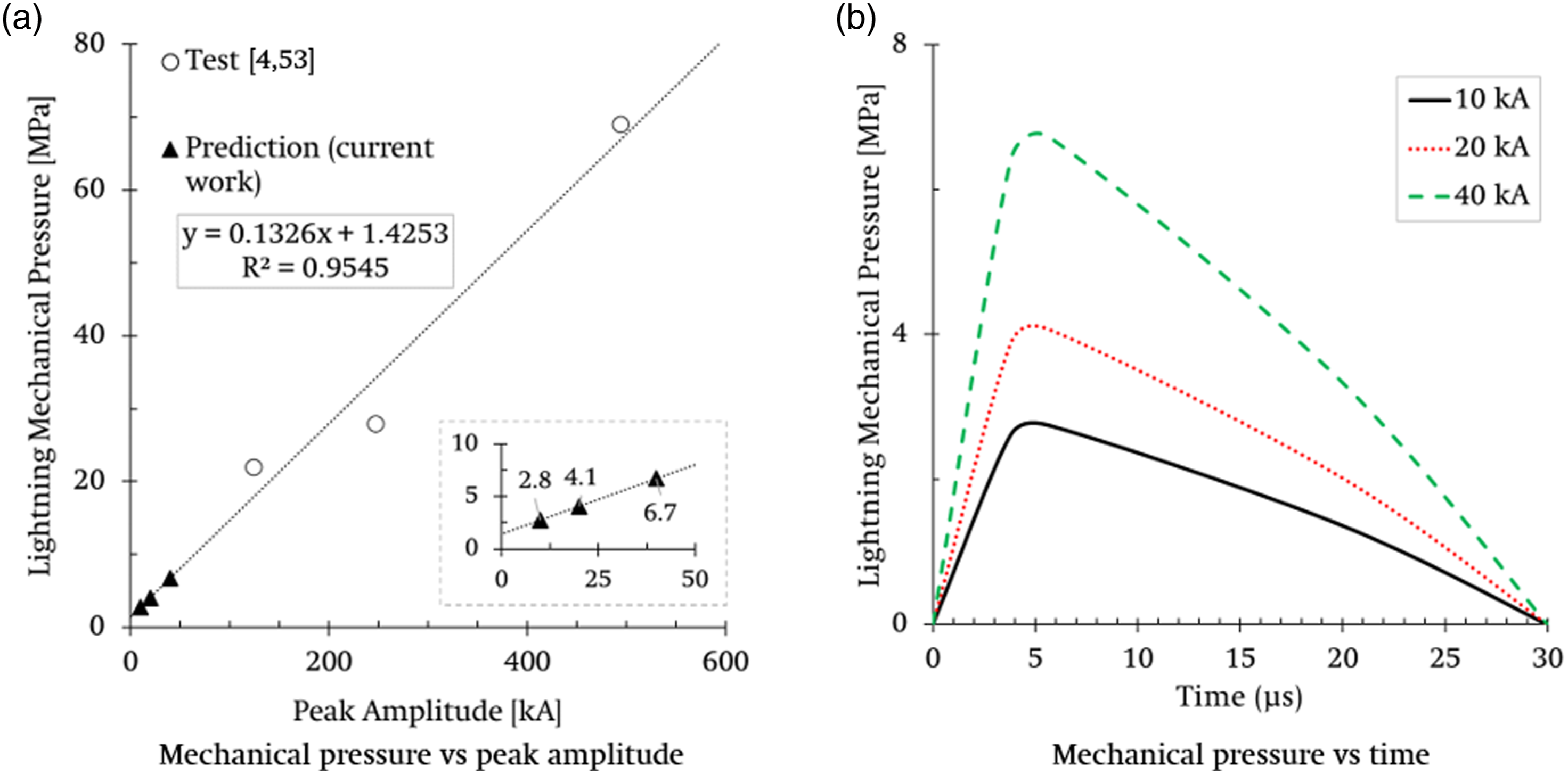
Elastic properties of carbon fibre and epoxy matrix.
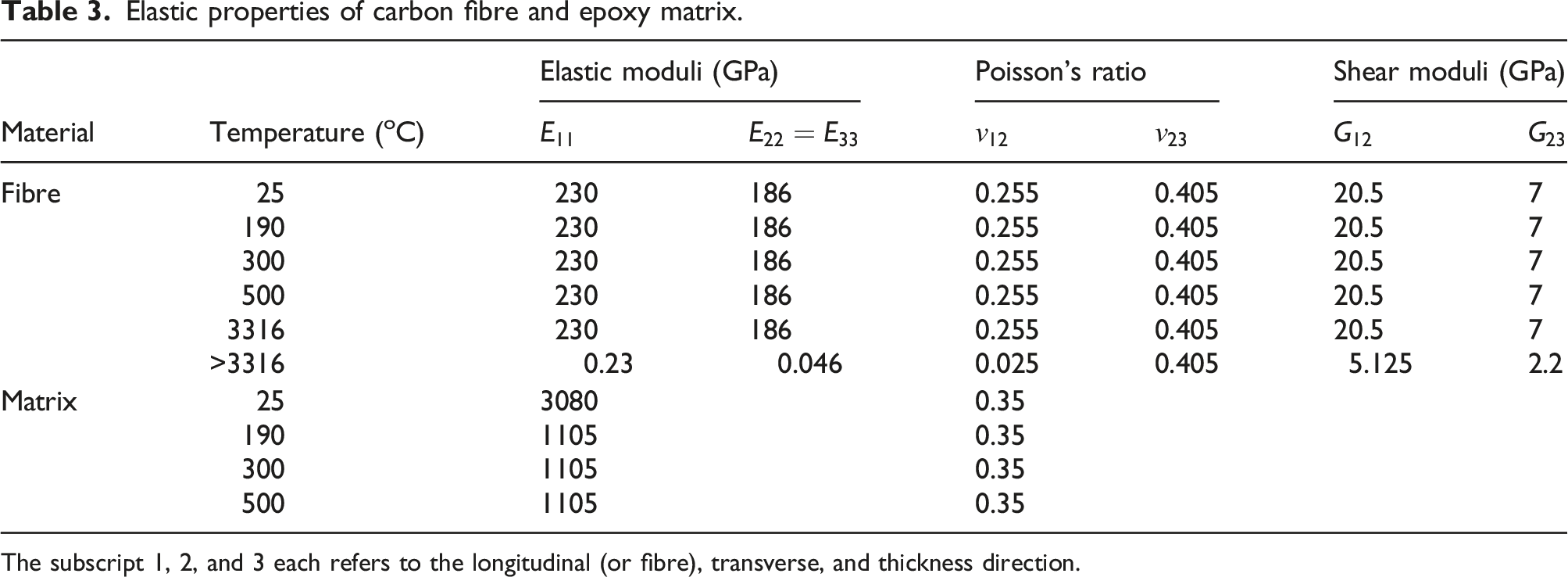
The subscript 1, 2, and 3 each refers to the longitudinal (or fibre), transverse, and thickness direction.
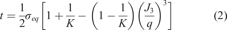
The epoxy matrix was modelled as isotropic and elastoplastic with a Drucker-Prager (DP) plasticity model coupled with progressive damage. A DP model was originally developed for geopolymer materials (i.e., soil, concrete) based on the Morh-Coulomb theory, but also widely used for modelling the failure of a polymer matrix with yield (hardening) behaviour. In this work, the ABAQUS built-in, modified DP model
55
was used to capture matrix failure. The DP yield function Fs is defined as
The evolution of DP yield surface was assumed to be controlled by the yield stress under uniaxial compression. The summary of the compressive yield stress and absolute plastic strain used in this work are tabulated in the following: [(30.095, 0), (61.93, 0.03), (61.93, 0.25)]. Hooputra et al.
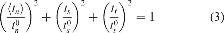
58
proposed a continuum ductile damage model predicting the ductile nature of noticeable plastic deformation of an epoxy matrix prior to damage initiation. Two material parameters are required in a ductile damage model to predict the onset of damage
Model summary
This modelling approach and its derivation is presented in further detail in Figure 6. The typical mesoscale model of a lightning strike on CFRP considers a specimen measuring 150 mm × 100 mm with a typical ply thickness ranging from 0.1-0.15 mm.2,16 The typical lightning arc is modelled with a diameter of 10 mm,
16
shown in Figure 6(a). The typical size of an RVE modelled in literature is around 50 μm × 50 μm × 50 μm with fibre diameters of 5.3–7 μm.44,45 Therefore, the models herein use this size of RVE and assume it is located at the top surface of the top ply in a typical laminate, shown in Figure 6(b). As such, the typical 10 mm lightning arc used in mesoscale lightning strike models will completely cover the top surface of the RVE, shown in Figure 6(c). Therefore, rather than applying the entire lightning waveform to the 0.0025 mm2 area at the top of the RVE, a scaling factor is used to account for the difference in area between the typical 10 mm arc and the size of the RVE. As a result, only the fraction of the current that would flow into the RVE is applied in each case. If this approach was not used, the applied current density and associated Joule heating would be significantly exaggerated and therefore exaggerate the predicted damage mechanisms. In fact, the actual gradients in the current density and initial arc channel radius are not known since they are strongly influenced by various factors, including the peak current amplitude, temporal characteristics, surrounding air conditions, and arc channel expansion velocity.1,54 Summary of representative volume element modelling approach and derivation of boundary conditions and thermo-mechanical loading from typical meso-scale models.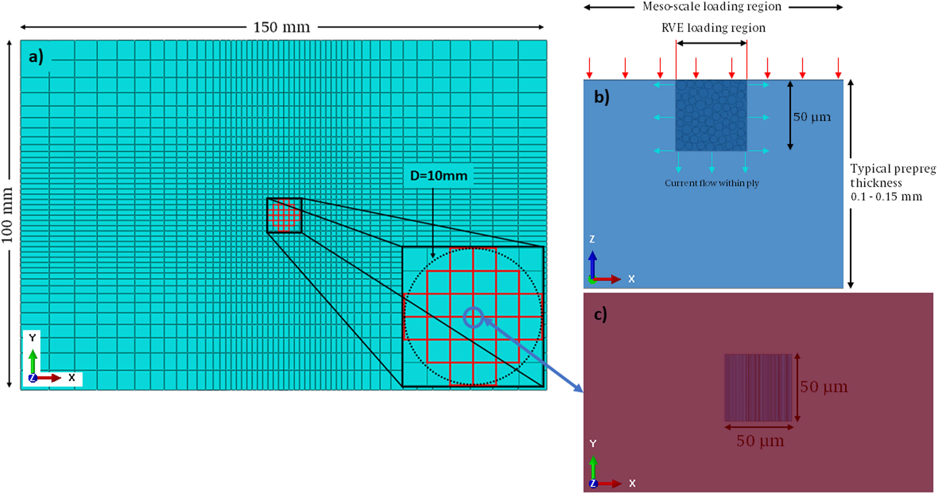
In addition, the boundary conditions studied herein have been chosen in order to capture the actual behaviour within the ply of a mesoscale level analysis and translate this to the RVE. When the current enters the ply (and the RVE) it can flow in three possible directions, along the fibres, transversely or through-thickness. This depends on the potential difference between the attachment (current injection location) and the grounding terminal, and electrical conductivity in each orthogonal direction. Each situation is therefore considered before choosing the most appropriate boundary conditions for further study.
While the typical mesoscale models of a lightning strike consider the specimens with multiple plies and the potential delamination damage between the neighbouring plies, this is beyond the scope of the models herein. Rather, the proposed RVE models can predict the fibre-matrix interfacial debonding in a small unit of a ply.
Lightning produces thermo-mechanical damage in composite specimens. Mechanical damage is highly localised and confined inside a lightning arc attachment. In addition, the mechanical damage area is fully surrounded by the thermal damage area, thus it is not straightforward to decouple pure mechanical damage from overall lightning damage since thermal, electrical, and mechanical damage occur simultaneously within the arc attachment area. 4 Therefore, in order to determine the contribution of different physics, pressure loading and thermal expansion, these were applied separately and then together. Therefore, three thermo-mechanical RVE models were completed with pressure loading only, temperature loading (associated with thermal expansion) only, and combined pressure-temperature loading. All simulations were completed on the Kelvin-2 High Performance Computing (HPC) cluster at Queen’s University Belfast.
Thermal damage results
In this section, coupled thermal-electric model results are discussed by focusing on the temperature distribution predicted within the RVE model. Typical epoxy matrix degradation occurs within the temperature range of 300–800°C, while carbon fibre damage occurs at temperatures greater than 3000°C. Therefore, these temperature ranges were used to characterise lightning-induced thermal damage within the RVE constituents. In general, since the carbon fibre damage region is totally encompassed by the widespread matrix damage region, lightning thermal damage in composites often corresponds to the extent of the matrix damage region. Along with this definition, lightning thermal damage calculated in an RVE model was estimated from the volume of the epoxy matrix region with temperatures ≥300°C or ≥500°C.
Effects of grounding condition
Three different electric potential boundary conditions were compared using a RVE model (V
f
= 55%) subjected to a 40 kA peak current load. Figure 7 shows predicted temperature distributions, indicative of lightning thermal damage in the epoxy matrix, within the RVE models when zero electric potential ground boundary conditions were applied to different RVE surfaces. Note that zero electric potential indicates a grounding terminal. As mentioned earlier, thermal decomposition occurs in typical epoxy matrices in the temperature range of 300 – 800°C. In this thermal decomposition temperature range, the epoxy matrix is progressively and irreversibly damaged due to pyrolytic matrix decomposition.
66
It can be seen that the addition of more grounding terminals reduced the predicted epoxy matrix damage significantly, limiting the peak temperature within the RVE model. This is reasonable since more grounding terminals allow electric current to exit, thus guaranteeing better current flow distribution (less Joule heating) over the RVE model. The effect of grounding conditions on representative volume element thermal damage prediction at t = 30 µs.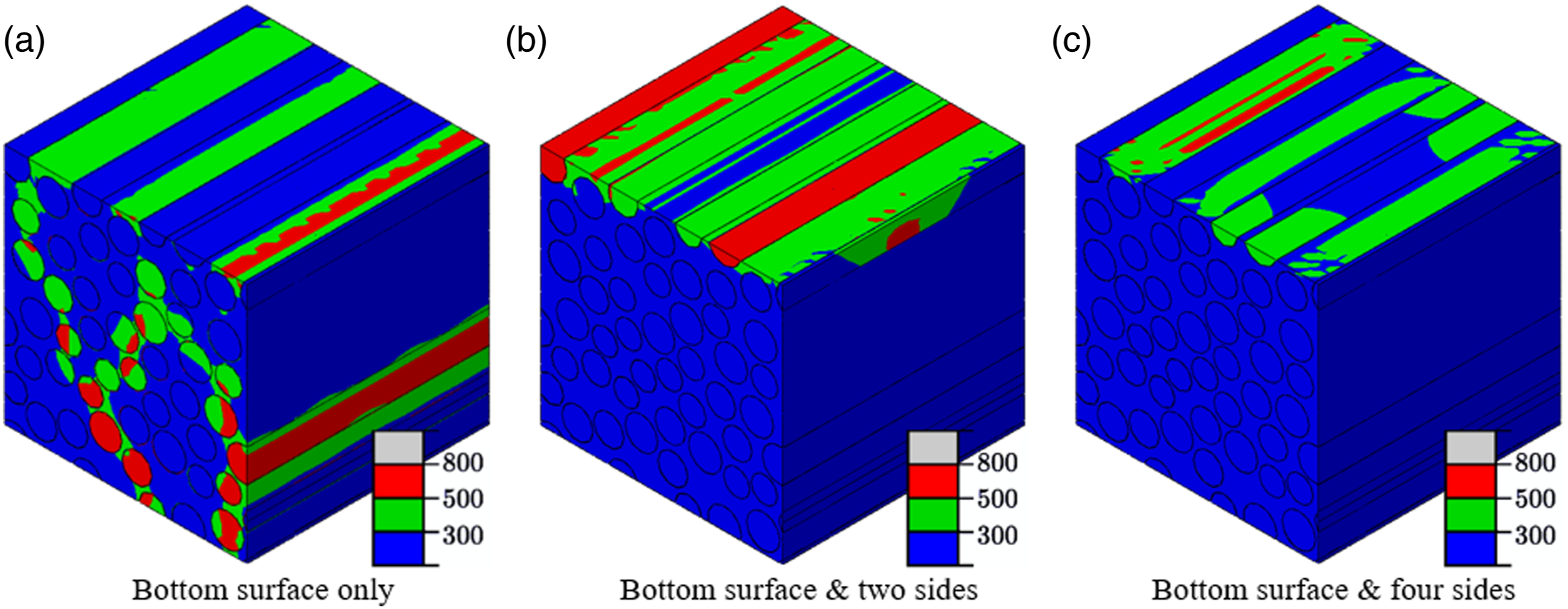
However, the most representative and interesting case is the RVE model with only the bottom surface grounded (Figure 7(a)). This RVE boundary condition can be assumed to represent the centre of the top ply on a large specimen under the direct influence of the lightning arc. Since even the smallest lightning arc channel (radius R ≥5 mm) is much larger than the RVE length (50 μm), the current likely tends to travel through-the-thickness of the RVE model rather than in-plane directions due to large potential difference, equivalent to voltage. As a result, only the bottom surface of each RVE will be grounded in the following simulations.
Initial assessment of the temperature profile in the carbon fibres of the RVE model with bottom surface grounding is based on Figure 7(a). Predicted temperature increases in carbon fibres are well below their sublimation temperature (∼3000°C), indicating no thermal damage. Note that the predicted maximum fibre temperature was 788°C in Figure 8. This can be explained by their comparatively large electrical conductivity compared to the epoxy matrix (Table 1). Therefore, further discussion of lightning thermal damage is primarily focused on the epoxy matrix regions of the RVE model. Fibre temperature distribution under 40 kA peak current amplitude at t = 30 µs.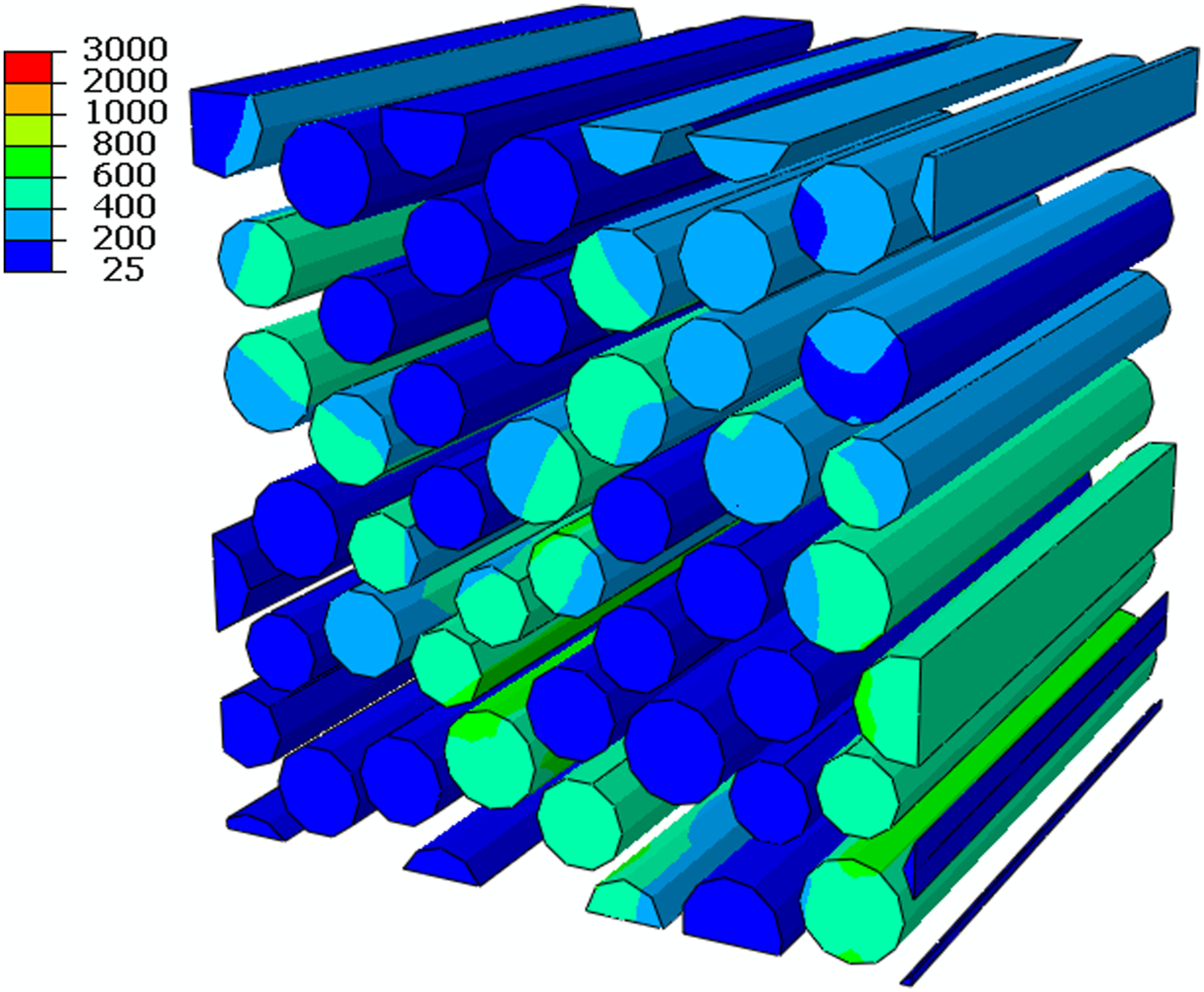
Effects of peak current amplitude
Figure 9 shows the predicted temperature distribution resulting from 10 kA, 20 kA and 40 kA peak current waveforms on the RVE models (V
f
= 55%) and corresponding epoxy matrix regions. In all cases considered, the most severe damage occurs at the top surface of the RVE model, where a uniform electric current is applied. In general, the carbon fibres are largely unaffected by the current load, however, the fibres which intersect with the loading surface do see a modest temperature increase, relative to their sublimation temperature. As the applied peak current increases, the extent of thermal damage onset (specifically damage to the matrix through Joule heating where the range 200–400°C represents moderate damage and 600°C and above represents matrix ablation), taken as the volume of the epoxy matrix with temperatures greater than 300°C, was nearly constant under 10 kA and 20 kA peak amplitudes, i.e., 1057 μm3 (10 kA) and 976 μm3 (20 kA), both around 2% of the total epoxy matrix volume. However, thermal damage onset under 40 kA peak amplitude increased significantly to 3920 μm3, corresponding to around 7% of the initial epoxy matrix volume. The extent of more severe thermal damage, taken as the volume of the epoxy matrix region with temperatures greater than 500°C increased steadily with increasing peak current from 545 μm3 at 10 kA to 2211 μm3 at 40 kA. The effect of a peak current amplitude on representative volume element thermal damage prediction at t = 30 µs.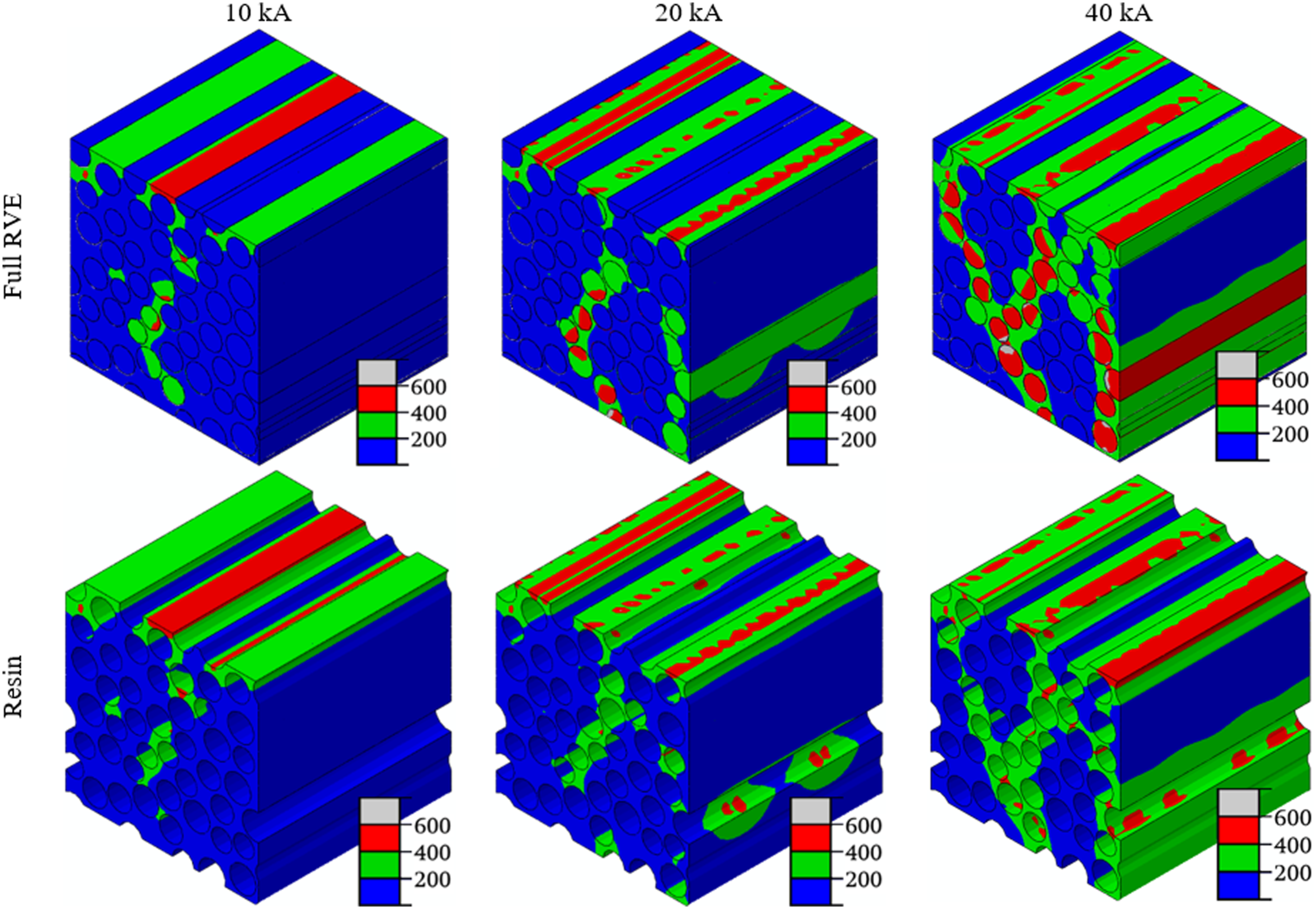
Figure 10 shows the primary current flow (or conduction) paths through each RVE model with varying peak current amplitudes (10–40 kA), established by inferring current flow through temperature contours, due to the Joule heating effect. It can be seen that the nearly identical current flow paths are produced in all cases. However, the amount of current flowing in each conduction path varies with peak current amplitude. This current was calculated by the sum of all nodes within each conduction path on the bottom surface of the RVE, shown on Figure 10(c). For the 55%-10 kA case (Figure 10(a)), 50% of the current leaves through the central flow path, Path 1, while this increases to 68% for the 55%-20 kA case (Figure 10(b)) and 80% for the 55%-20 kA case (Figure 10(c)). This suggests that a primary conduction path is mainly dictated by the fibre distribution, but its magnitude is strongly controlled by the incident peak current amplitude. This hypothesis is further explored when varying V
f
in the following section. Primary conduction paths through representative volume element models with varying peak current amplitudes at t = 15 µs.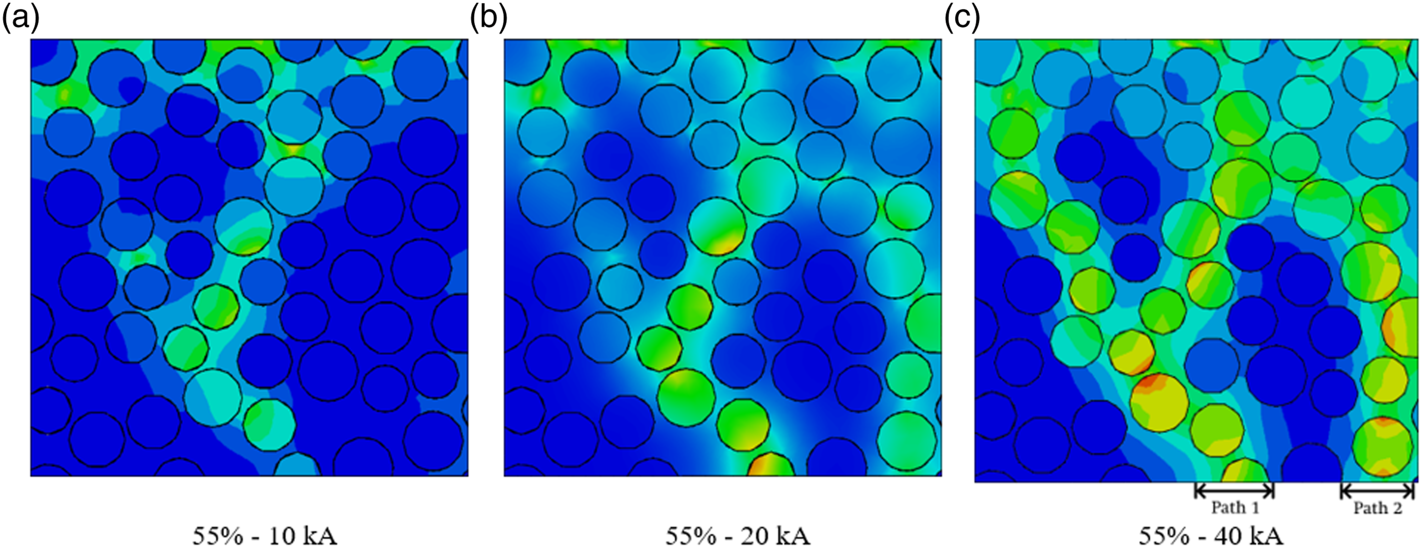
Figure 11 shows the development of the primary (red) and secondary (black) conduction paths, i.e. the larger and smaller of the main current flow paths, through the RVE model (V
f
= 55%, 40 kA) at three time points, t = 6 μs, 12 μs and 30 μs, respectively. These times were chosen as they correspond to 20% (just after Primary and secondary conduction paths in the representative volume element model (Vf = 55%, 40 kA).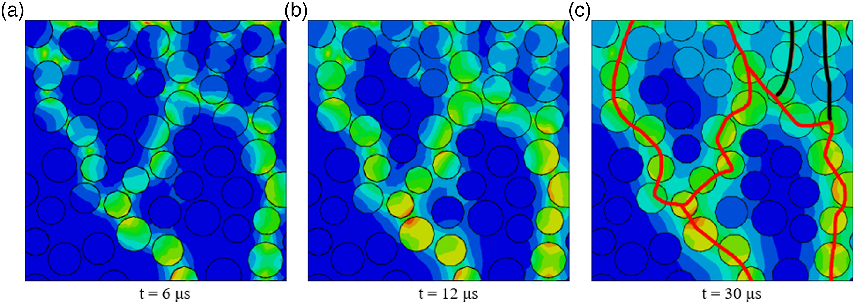
Effects of fibre volume fraction
Figure 12 shows the temperature distribution predicted from 40 kA peak current on the RVE models with V
f
= 55%, 60%, and 65%, respectively. As observed previously, the carbon fibres are largely unaffected, even at higher V
f
. As V
f
increased, the extent of thermal damage onset in the RVE models increased from 3920 μm3 (55%-40 kA case, Figure 12(a)) to 5121 μm3 (60%-40 kA case, Figure 12(b)) to 5918 μm3 (65%-40 kA case, Figure 12(c)). These thermal damage volumes correspond to 7%, 10%, and 14% of the pristine (undamaged) epoxy matrix volumes, respectively. However, the volume of more severe damage (taken as >500°C) decreased with increasing V
f
from 2211 μm3 (55%-40 kA) to 285 μm3 (65%-40 kA). The predicted peak temperature within each RVE model decreased with increasing V
f
from 788°C (Figure 12(a)) to 590°C (Figure 12(c)). This makes sense since more carbon fibres spread electric current more rapidly, causing less Joule heating within the epoxy matrix and, therefore less temperature increase in each RVE model. When the threshold temperature was 300°C, predicted thermal damage increased steadily with increasing V
f
. In contrast, with a threshold temperature of 500°C, predicted thermal damage decreased with V
f
. Therefore, this somewhat counterintuitive behaviour may be a result of the chosen threshold temperatures. The effect of Vf on representative volume element thermal damage prediction at t = 30 µs.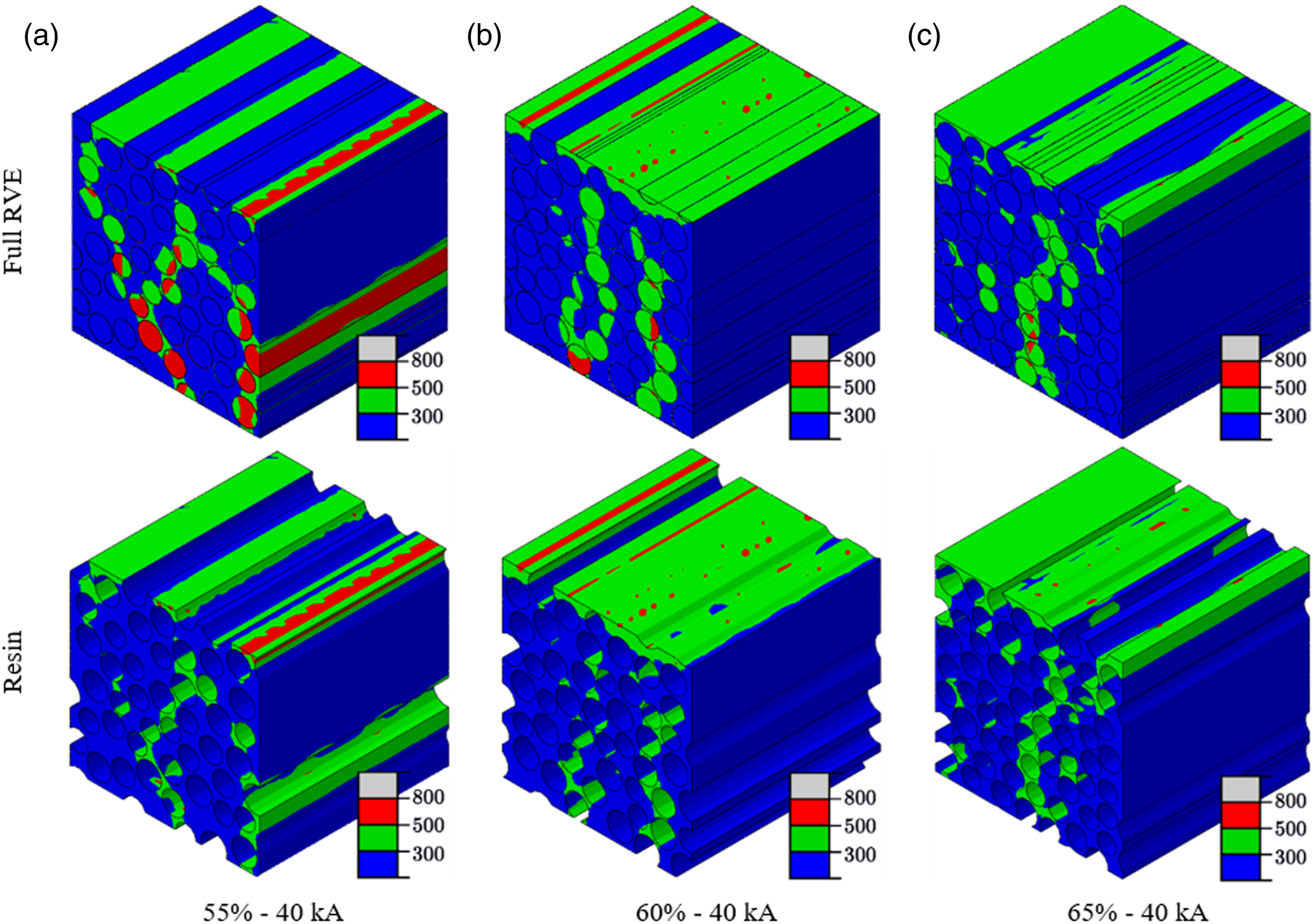
Figure 13 shows the predicted current conduction paths, from the RVE models with V
f
= 55%, 60%, and 65%. While the nearly identical current flow path was predicted at a fixed V
f
(Figure 10), modifying V
f
produced significant changes in the flow of current. For example, when V
f
= 55%, the flow of current was divided over two paths (Figure 13(a)). The rightmost flow path took around 37% of the current, while the central path took around 63% of the current. Increasing V
f
to 60% produced a more uniform current spread over three broad columns of fibres (Figure 13(b)). Finally, increasing V
f
to 65% spread the current over the majority of the RVE model with one localised region of high current density down the approximate centre of the RVE model (Figure 13(c)), accounting for around 24% of the current flow. The nature of this primary conduction path formation is highly influenced by the distance between each fibre, associated with fibre diameter characteristics (i.e., mean and standard deviation). Primary conduction paths generated in the representative volume element models with varying Vf at t = 15 µs.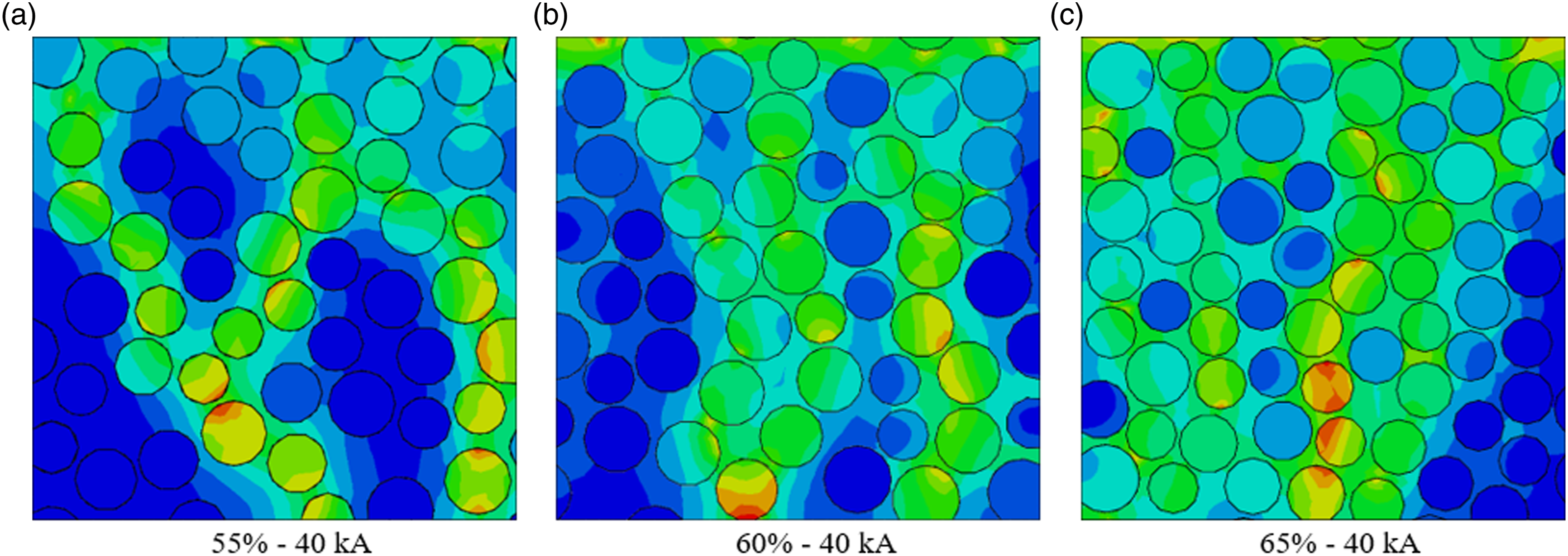
Thermo-mechanical damage results
This work proposed a sequentially coupled thermo-mechanical modelling framework to predict lightning thermo-mechanical damage in a RVE model. Heat transfer primarily takes place via conduction within a RVE model and requires some time (likely a few seconds) to achieve thermal equilibrium. Thermal damage, resulting from Joule heating due to the application of current, may be accelerated due to thermal strain - the product of the coefficient of thermal-expansion (CTE) and a temperature change. In addition, lightning damage may become worse with dynamic mechanical loading (i.e., lightning shockwave overpressure). The following sections highlight thermo-mechanical damage prediction in the RVE model each obtained from dynamic pressure loading, temperature loading (due to thermal strain), and its combined effects.
Pressure loading only
Figure 14 shows the stress generated in the matrix of the 65%-40 kA RVE model under pressure loading only. Note that a 40 kA peak current amplitude is equivalent to 6.7 MPa lightning shockwave overpressure (Figure 5(a)). It can be seen in Figure 14 that the magnitude of stress reached a maximum of 2.7 MPa, well below that which would cause both carbon fibre and epoxy matrix damage. This indicates that dynamic pressure loading equivalent to a 40 kA peak current amplitude does not induce severe mechanical stress within the RVE. This is consistent with work done by Refs 4,24,26,49,54, who despite using much larger specimens, e.g. 150 mm × 100 mm, also found negligible damage from lightning mechanical loading alone. This is an important finding as lightning mechanical damage does not influence the overall lightning damage in a RVE model, so there is no need to decouple it from lightning damage assessment. Stress predicted in the matrix region of the representative volume element model (Vf = 65%) under only pressure loading equivalent to 40 kA peak current at t = 30 µs.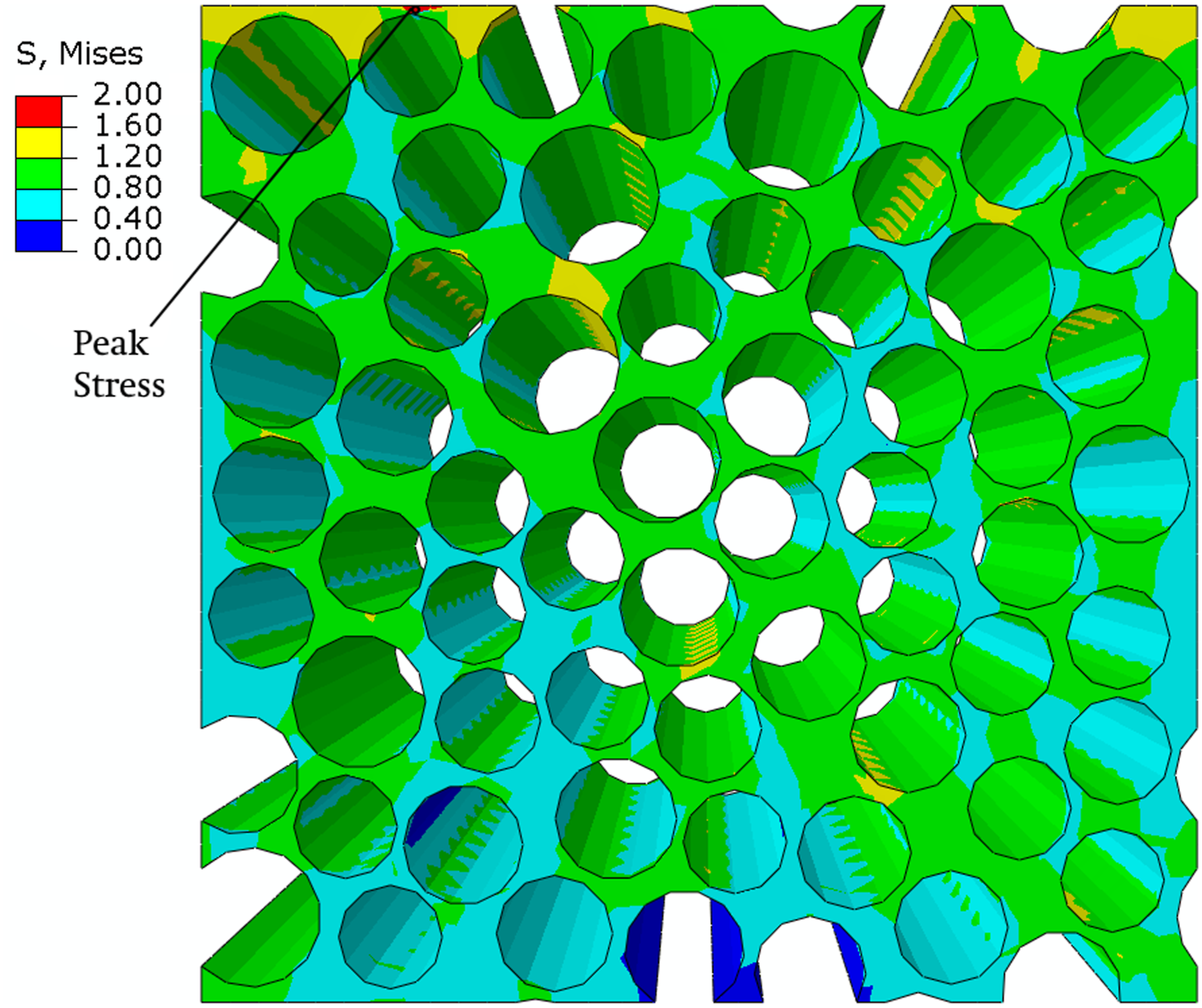
Temperature loading only
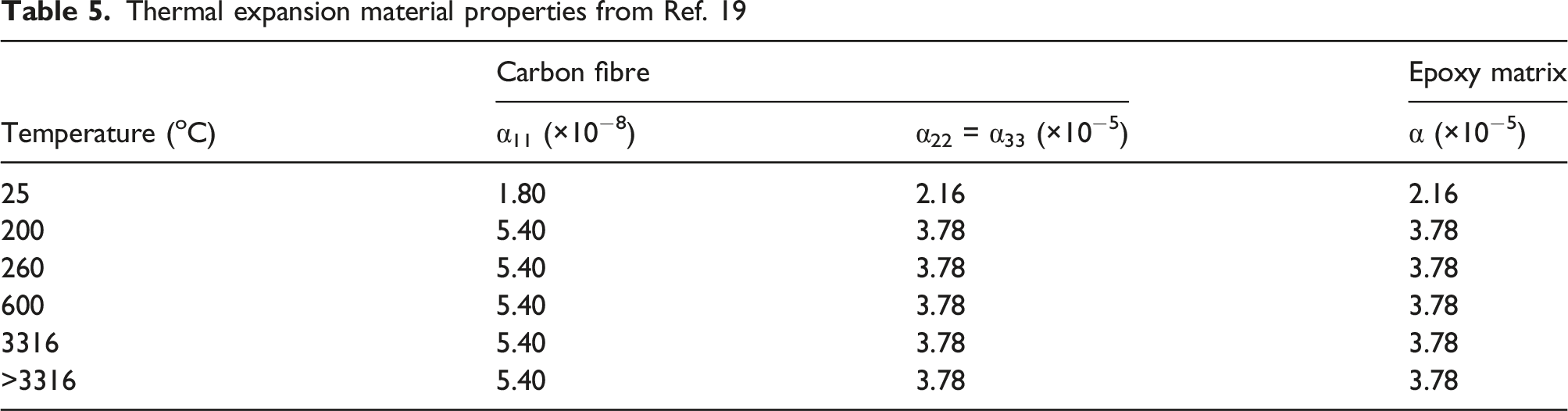
The temperature loading defined herein indicates the temperature profile transferred from the preceding thermal-electric analysis. The effects of thermal strains (associated with thermal expansion during thermal equilibrium) on thermo-mechanical damage can be evaluated in an RVE model. Results for temperature loading are more interesting and severe than pressure loading only. Figure 15 shows the predicted equivalent plastic strains (PEEQs) contours of the 55%-40 kA and 65%-40 kA RVE models. The RVE deformation and corresponding PEEQ strains are higher for the 55%-40 kA RVE model than the 65%-40 kA RVE model due to a large volume fraction of relatively “weak” matrix (i.e., the epoxy matrix is mechanically weaker than the carbon fibres). In addition, the CTE mismatch between carbon fibres and epoxy matrix contributes to significant RVE deformation, i.e., 5.40 × 10⁻⁸ (carbon fibre) versus 3.78 × 10⁻⁵ (epoxy matrix) at 260°C from Table 5. The 55%-40 kA RVE model exhibits a somewhat continuous strain path developed within the narrow regions between fibres (highlighted in green in Figure 15(a)). Predicted PEEQ distributions on the 55%-40 kA and 65%-40 kA representative volume element models at t = 30 µs.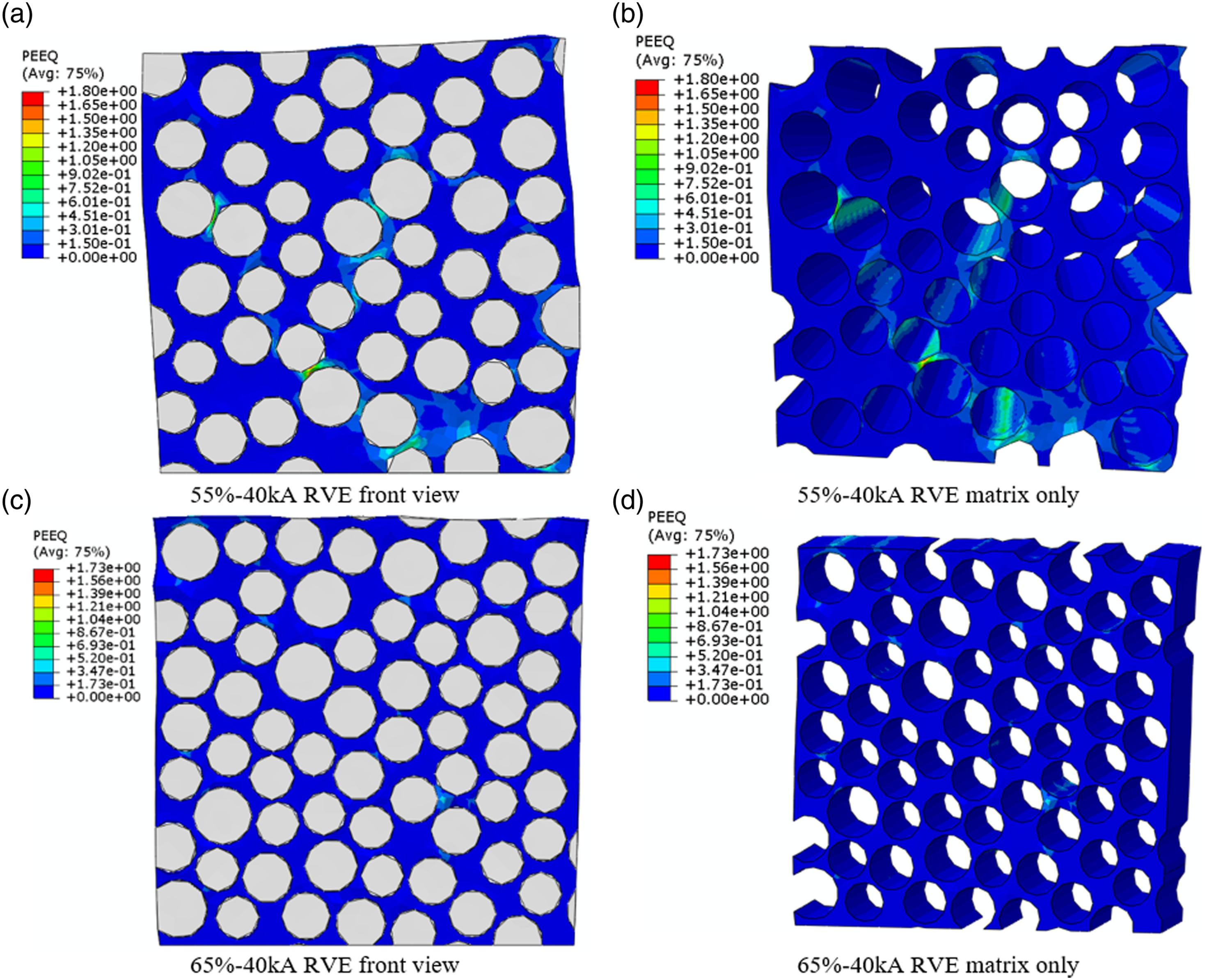
Figure 16 shows the predicted ductile matrix damage for both the 55%-40 kA and 65%-40 kA RVE models. Comparing Figure 16 and Figure 12, it can be seen that the ductile matrix damage closely matches the thermal damage profile, resulting from Joule heating, predicted in the corresponding thermal-electric models, particularly for the 55%-40 kA model. As with PEEQ, there was significantly more ductile damage in the 55%-40 kA RVE model due to a large volume of (relatively weak) matrix-rich areas. An amount of ductile matrix damage may be associated with the mean and standard deviation (STD) of fibre-to-fibre distances. This is greatly dependent on the effect of fibre positioning and variability in the fibre-to-fibre distance associated with V
f
. For example, looking at the widest region of ductile damage on the 55%-40 kA RVE model, bottom right of Figure 16(a), the average fibre-to-fibre distance was 2.1 μm while in the same region of the 65%-40 kA RVE model the average fibre-to-fibre distance was 0.8 μm. Predicted ductile matrix damage in (a) 55%-40 kA and (b) 65%-40 kA representative volume element models at t = 30 µs.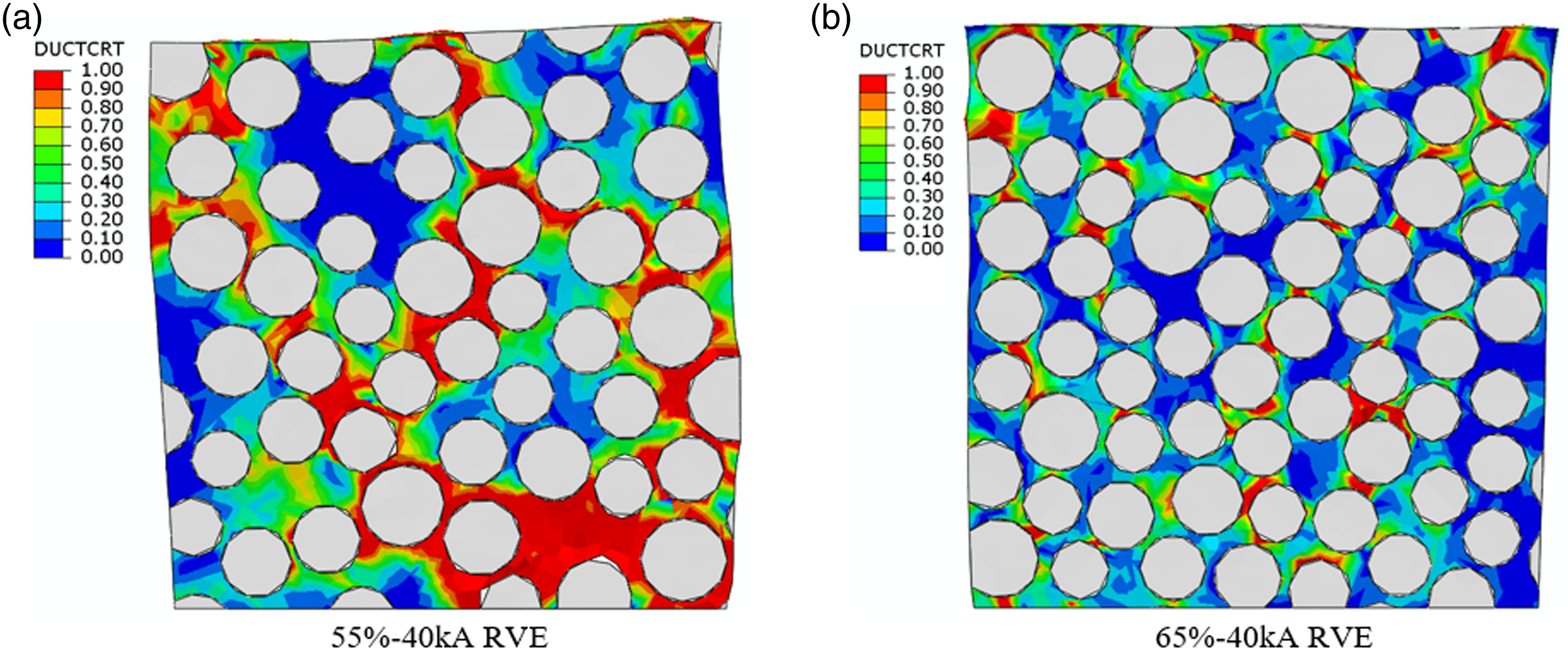
Comparing Figure 13 with Figure 16, the primary conduction paths generally match the severe damaged matrix regions (in red) with relatively large fibre-to-fibre distances. More investigation is required to further understand the effects of fibre distribution on subsequent ductile matrix damage development.
As a quantitative measure of overall thermo-mechanical damage in the RVE models, the total damage volume was calculated based on the value of the ductile damage initiation criteria (DUCTCRT), i.e., ≥0.99. The resulting matrix damage for the 55%-40 kA RVE model was 17,523 μm3 (14% of the full RVE model and 31% of the matrix region) and 4514 μm3 (4% of the full RVE model and 8% of the matrix region) for the 65%-40 kA RVE model.
Figure 17 shows the stress distributions predicted within the matrix and fibre regions for both 55%-40 kA and 65%-40 kA RVE models. In both cases, the stresses within the matrix were relatively low, only with mild stress concentration. In the 55%-40 kA RVE model, the peak fibre stress occurred in the central fibre with largest current flow (63% of the current), as highlighted earlier. In the 65%-40 kA RVE model, fibre stress was much more uniform across all fibres. In both cases, the areas of matrix with high stress closely matched the regions with severe matrix damage (Figure 16). Note that the RVE model presented herein consisted of randomly distributed carbon fibres within the epoxy matrix. Thus, the regions of relatively high stress concentration can be varied depending on fibre arrangement and volume fraction. Predicted stresses within the matrix and fibres for both 55%-40 kA and 65%-40 kA representative volume element models at t = 30 µs.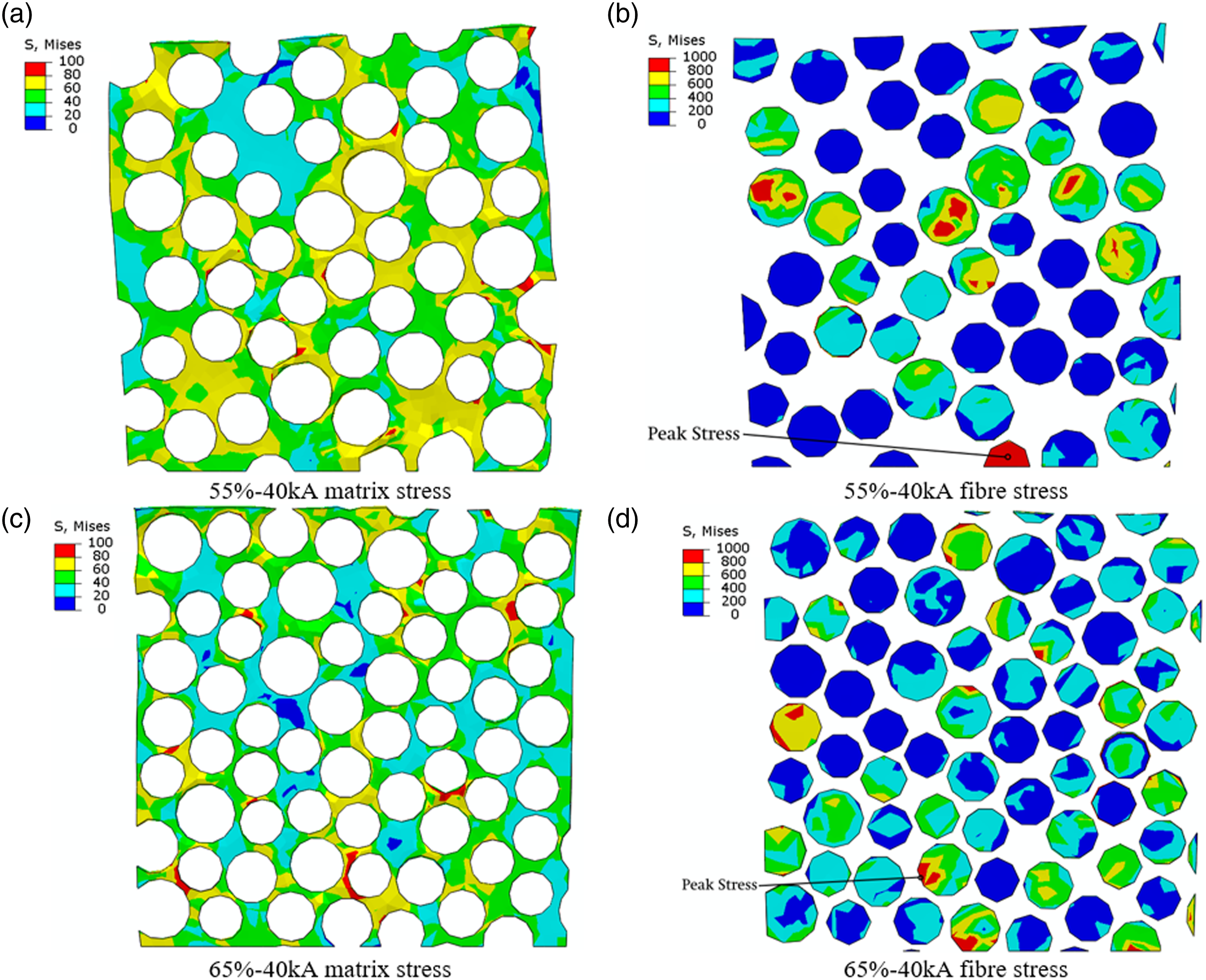
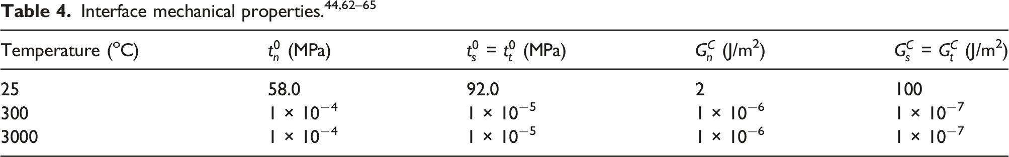
Figure 18 shows the predicted fibre-matrix interfacial debonding in both the 55%-40 kA and 65%-40 kA RVE models. As with other damage modes, the predicted fibre-matrix interfacial debonding closely matched the thermal damage profile (Figure 12) and primary current flow paths (Figure 13). While interfacial damage generally followed the thermal damage profile, this damage mode was somewhat independent of the ductile matrix damage profile. This is likely due to the temperature dependence of the interlaminar properties, shown in Table 4. As with other damage modes, interfacial damage varies with V
f
. The interfacial damage, taken as the area of the cohesive surface damage criteria (CSDMG) ≥0.99, was 274 μm2 for the 55%-40 kA RVE model, but only 72 μm2 for the 65%-40 kA RVE model. Predicted fibre-matrix interfacial damage in the 55%-40 kA and 65%-40 kA representative volume element models at t = 30 µs.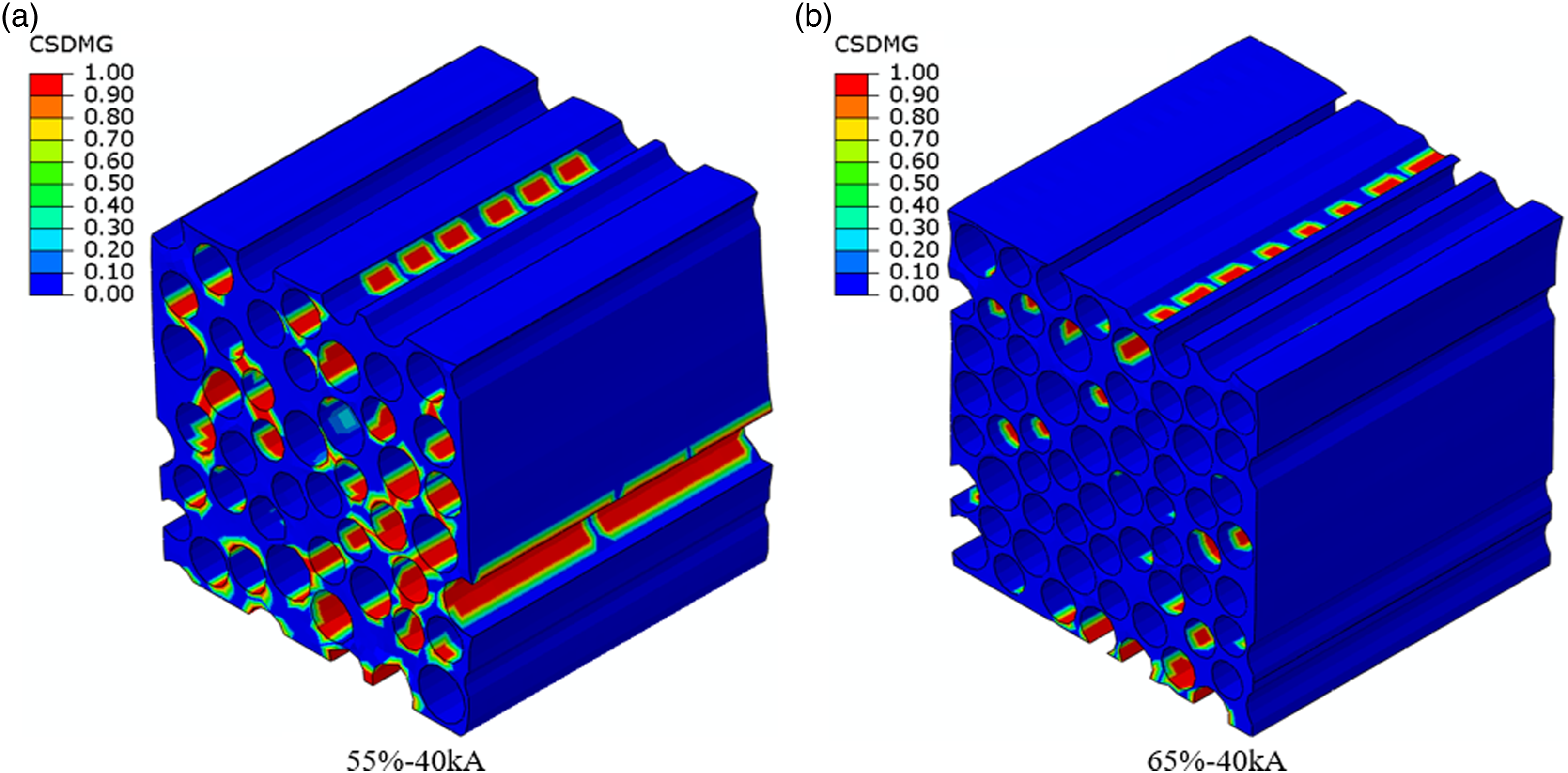
Debonding between the carbon fibres and epoxy matrix was also observed within the 55%-40 kA RVE model subjected to thermal loading only. Figure 19(a) shows the resulting fibre-matrix debonding in the whole RVE and in a zoomed-in image. In both cases elements with DUCTCRT ≥0.99 have been removed since fibre-matrix debonding can occur due to a combination of matrix damage and interfacial damage. As shown in Figure 19(a), the RVE model can predict considerable fibre-matrix interfacial debonding, consistent with the scanning electron microscope (SEM) images (Figure 19(b) and (c)) of representative carbon/epoxy laminates subjected to a 38 kA peak current amplitude.
67
This is important for evaluating various damage modes in the lightning attachment location. The RVE model proposed in this work, to the best of the authors’ knowledge, is the first model predicting lightning-induced fibre-matrix interfacial damage. Interfacial fibre-matrix debonding prediction at t = 30 µs compared with SEM images from Ref. 67.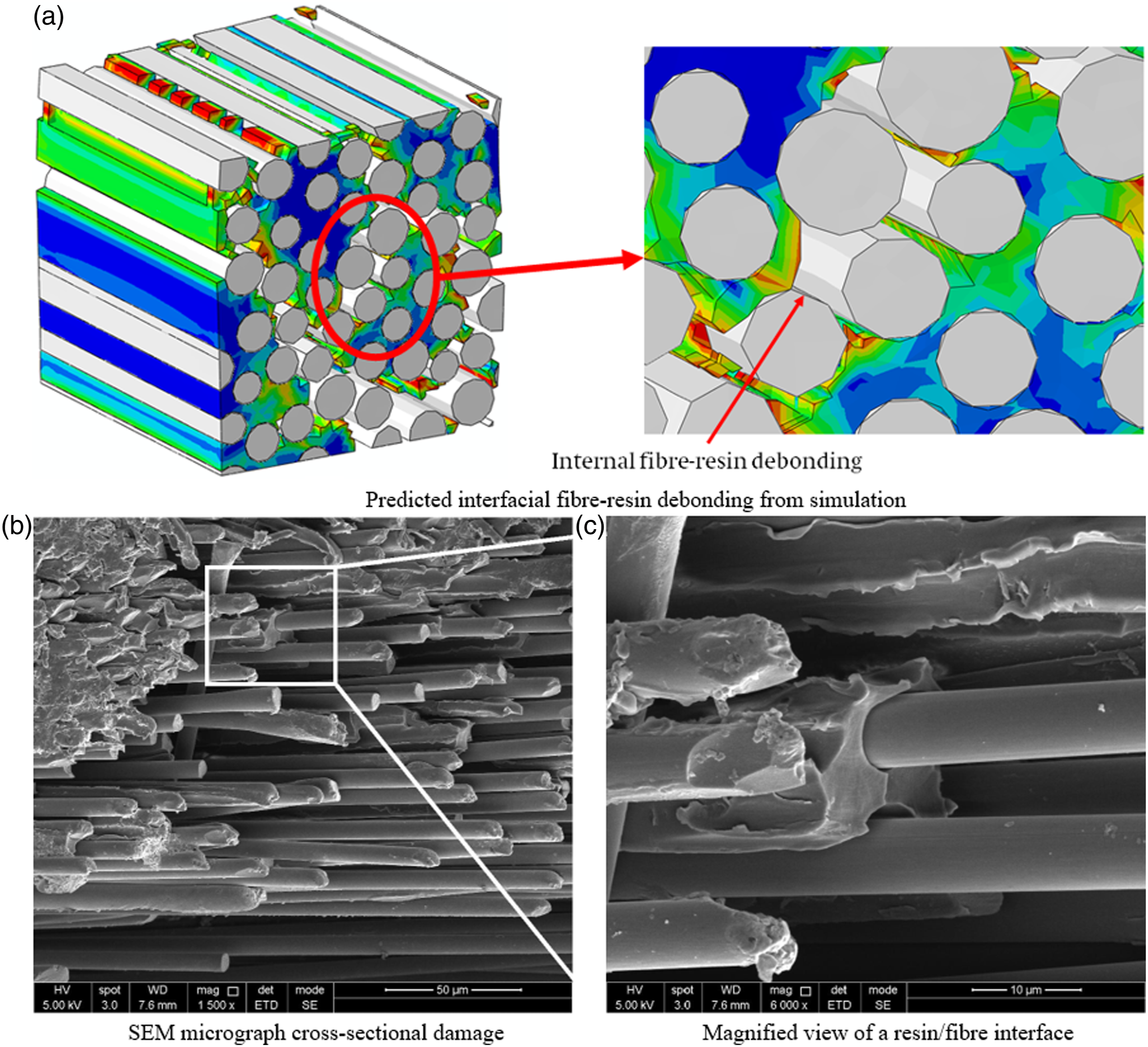
Combined pressure-temperature loading
As expected, results for combined pressure-temperature loading show a small difference to the results with temperature loading alone. The matrix damage volume for the 55%-40 kA RVE model with temperature loading only was 17,523 μm3, while this increased slightly to 18,483 μm3 (<5%) with the addition of pressure loading. This finding again confirms a negligible effect of lightning mechanical loading on overall damage assessment.
Results summary
In a CFRP composite, the polymer matrix undergoes severe thermal decomposition when subjected to a lightning strike. The matrix decomposition (occurring due to pyrolysis) results in irreversible thermal damage. The extent of irreversible matrix damage, indicative of lightning thermal damage in a CFRP composite, strongly depends on a thermal decomposition temperature range (300–800°C, herein) and a heating rate. At the lightning attachment location, the rate of temperature increase may locally exceed 10,000°C/min 7 and the onset and evolution of irreversible thermal damage may require a different decomposition temperature range to assess more accurate lightning thermal damage. Similarly, a quantitative measure of thermo-mechanical damage may depend on a threshold value of DUCTCRT.
Summary of thermal damage, peak temperature, and mechanical damage for representative volume elements.
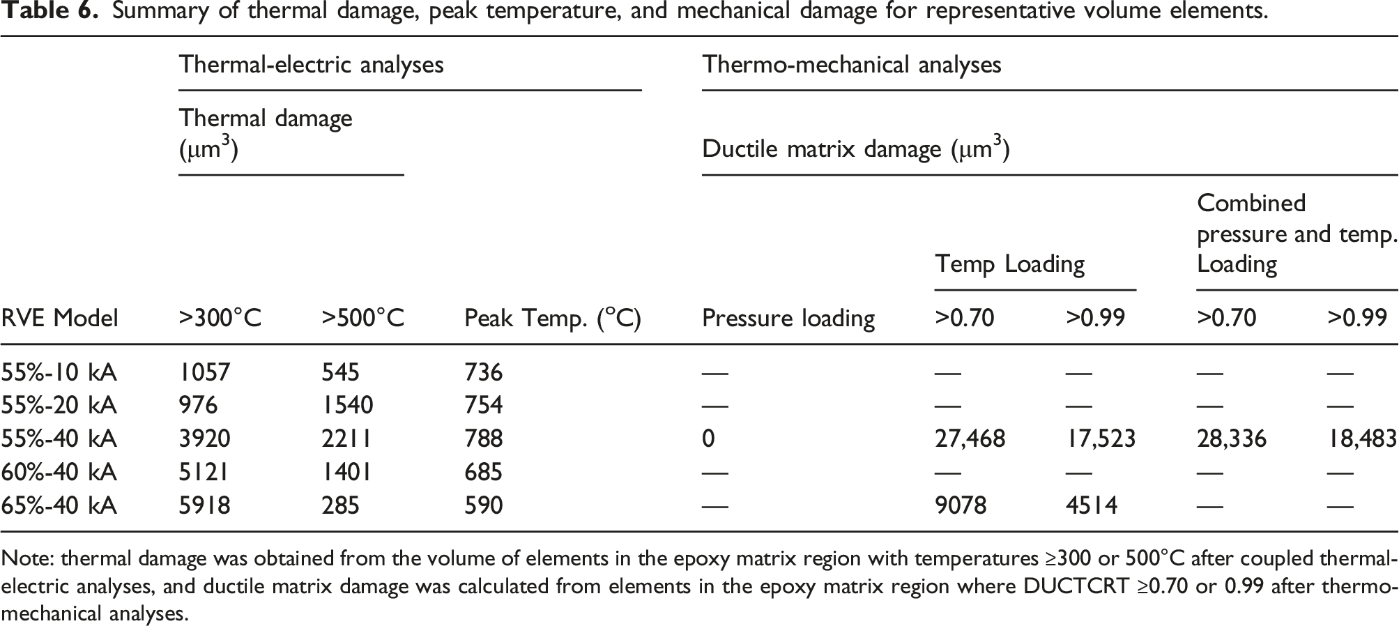
Note: thermal damage was obtained from the volume of elements in the epoxy matrix region with temperatures ≥300 or 500°C after coupled thermal-electric analyses, and ductile matrix damage was calculated from elements in the epoxy matrix region where DUCTCRT ≥0.70 or 0.99 after thermo-mechanical analyses.
Limitations and future work
The proposed RVE-based models presented previously have, for the first time, been developed to characterize complex lightning damage mechanisms at a fundamental level, i.e., in the fibre, matrix and fibre-matrix interface. In contrast to macroscale models where all loading/boundary conditions are directly monitored by actual lightning tests, our microscale models were developed with some assumptions since these were unknown at a fundamental level.
It was assumed that the loading and grounding of the microscale models could be derived from the macroscale/mesoscale models widely used in literature, with the approach in this paper shown in Figure 6. While lightning damage in mesoscale models is driven by the current distribution4,68 and the boundary conditions 49 of the experiment and corresponding model, deriving the exact loading and grounding of an RVE scale model is challenging. Since these are location- and time-specific; these are basically unknown and require some idealisation. Therefore, this work has assumed that (current and mechanical) loading on an RVE surface will be a fraction of the total arc loading. Grounding of the side surfaces would force the current to flow into particular sides of the RVE modelling region. In reality, at a macroscale, the current distribution is driven by impedance and electrical potential. Therefore, this work has assumed that since the RVE loading surface will be totally encapsulated by even the smallest lightning arc channel (R ≥5 mm) the impedance and electrical potential will be uniform in the in-plane directions but will vary in the through-the-thickness. This is assumed to promote current flow through-the-thickness of the RVE, hence the choice of bottom surface grounding. Note that we considered three representative grounding conditions that may provide their upper and lower limits. Future work could further enhance and validate these assumptions by incorporating the RVE in a mesoscale model and completing multi-scale modelling to further understand the loading and grounding required for modelling of microscopic behaviour only i.e., creating a model as shown in Figure 6(b).
The material properties assumed in this work have been derived from the mesoscale models used in literature. For example, the electrical conductivity of the epoxy matrix was derived from the value used for through-thickness conductivity in mesoscale models (i.e. “resin-rich” regions) in preceding research.2,4,19 Further work is required to establish the temperature dependent electrical and thermal properties of the individual fibres and matrix at conditions suitable for a lightning strike. Percolation effects,48,69 which can influence through–thickness properties, should be considered in future work. These interfacial effects could be incorporated in the current RVE models using cohesive elements with thermal and electrical gap conductances. Higher and lower interfacial conduction could be simulated by adjusting the cohesive layer thickness and gap conductance. In addition, once the matrix reached a char state it was assumed the conductivity reached 1 × 10⁵ 1/Ω.mm, in line with previous research.2,4,19 This value was used to represent matrix sublimation without complex element deletion. However, the exact conductivity of the char material may be smaller than the conductivity of carbon fibres in the through-thickness direction. Therefore, further development to incorporate accurate element deletion and matrix charring would enhance the models.
Conclusions
A series of three-dimensional (3D) representative volume element (RVE) models were developed to predict lightning-induced thermal and mechanical damage of unidirectional carbon fibre-reinforced epoxy matrix composite laminates. The RVE models were created with random fibre distribution in epoxy matrix, all measuring 50 μm × 50 μm × 50 μm. The effects of various grounding conditions (one-, two-, and four-side grounding), fibre volume fractions (V f = 55, 60%, and 65%), and peak current amplitudes (10, 20, and 40 kA) of applied impulse waveforms on microscopic damage in RVE models were characterized to better understand various damage mechanisms associated with lightning strikes. The proposed microscale lightning thermo-mechanical damage models are fundamentally different from the normal mesoscale or macroscale analyses used to predict the overall lightning damage in composite laminates. The primary goal of this work was to characterize complex lightning damage mechanisms at a fundamental level, not to assess the severity of overall lightning damage in composite laminates.
A two-step sequential modelling procedure was applied to decouple (i) thermal damage predicted using a coupled thermal-electrical model and (ii) thermo-mechanical damage obtained from subsequent dynamic pressure loading, thermal loading, and its combined effects. Predicted thermal damage was almost constant up to 20 kA peak current, before increasing significantly at 40 kA peak current. An increase in V f steadily decreased the extent of severe thermal damage in the RVE models. Thermo-mechanical simulations showed that subsequent dynamic pressure loading was negligible and thermal loading associated with thermal strain/expansion had the largest contribution to thermo-mechanical damage during a lightning strike.
One limitation of the proposed model is that it does not account for carbon fibre damage. This may be acceptable since each fibre is surrounded by widespread matrix damage, thus total lightning damage is nearly equivalent to the matrix damage. Accurate modelling of carbon fibre damage should consider sequential chemical reactions including oxidation, char formation due to matrix decomposition, and ablation/sublimation near their critical temperature (∼3000°C). Although one can model these complex damage mechanisms, carbon fibre damage is highly localised, so cannot represent total lightning damage in carbon/epoxy composites.
Footnotes
Declaration of Conflicting Interests
The author(s) declare no conflicts of interest with respect to the research, authorship, and/or publication of this article.
Funding
The author(s) received no financial support for the research, authorship, and/or publication of this article.