
Abstract
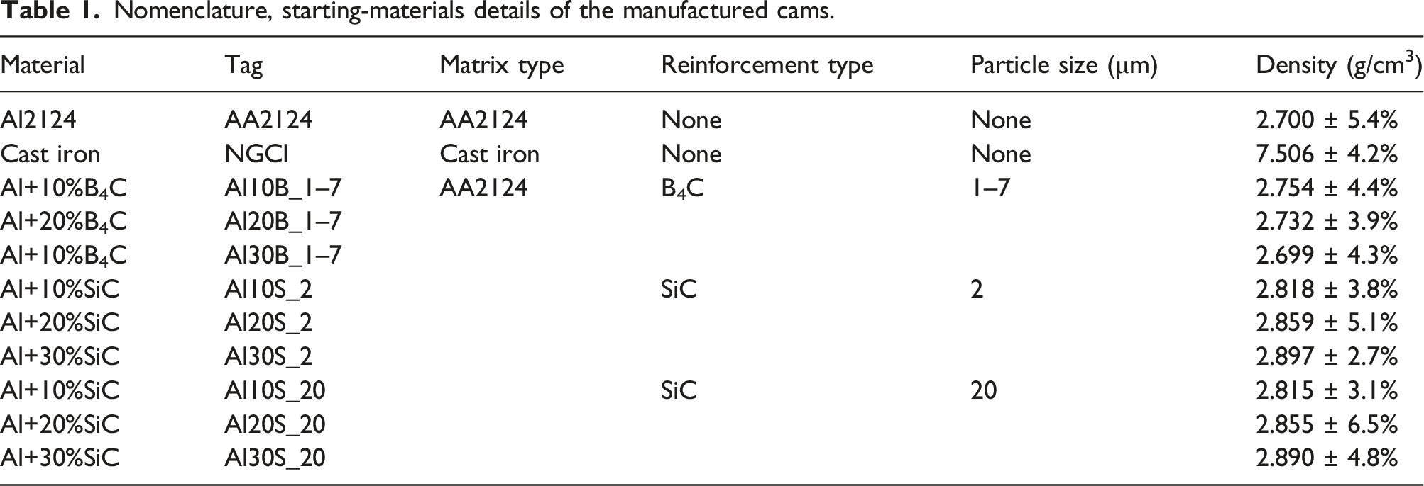
The integral engine parts, such as camshaft members, are usually not preferably made of ceramic-reinforced MMC because the margin of compromise on the engine performance is small. However, the lightweight and wear-resistant nature of the mentioned materials can benefit fuel consumption without necessarily compromising engine performance. In this study, Al (AA2124) matrix is reinforced with ceramic particles of two different types (SiC, B4C), size distributions (B4C: 1–7, SiC: 2 and 20 μm), and volume fractions (0, 10, 20, 30 vol.%) to manufacture camshaft cams (lobes). While MMC cams are manufactured by powder metallurgy (300 MPa, 615°C, 30 minutes), spherical graphite cast iron (GGG40) cams are prepared by casting, induction hardening, and machining. The wear behavior of MMC cams is compared with the reference unreinforced AA2124 and conventionally used cast iron cams under dry and virtually created engine-like wet conditions. It was attempted to correlate the percentage increase in the roughness and weight loss with the structure of the cams using SEM, EDX, and macroscopy analysis. Results showed that the initiation of a three-body abrasive wear mechanism for 30 vol.% of the larger SiC particles caused lower wear resistance in the cams under dry conditions. As for the wet conditions, although the cams’ wear resistance increased with increasing ceramic particles’ content, it resulted in enhanced wear in the counterface when larger ceramic particles were used as reinforcement. Overall, higher ceramic content and larger particle size encourage three-body abrasive wear between the interacting surfaces and assist in degraded wear resistance under wet conditions.
Introduction
While the camshaft is considered the heart of the engine, the lobes (cam profiles) responsible for the opening and closing of the valves also have a determinant influence on the performance of the engine.
1
The physical characteristics of the cam profiles (Figure 1) determine the amount, duration, and speed of the valve opening for fuel injection into the engine. The distorted geometry of the cams restricts the complete opening of the fuel injection valves and reduces the engine efficiency.
2
Although modern lightweight composites have revolutionary taken over the majority of automobile equipment, the least margin of compromise on the performance has restricted the integral parts of the engine to be preferably made of high-density ferrous materials. Profile and nomenclature for different regions of the cams.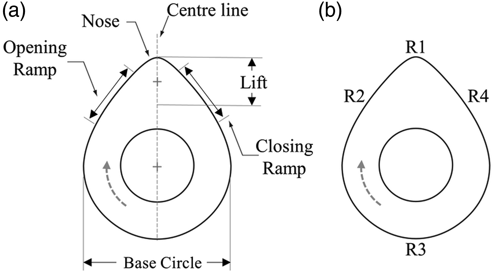
Due to the physically interacting nature of the cams’ operation, wear appears to be the primary functional issue that needs proper addressing. 3 Other than the post-manufacture in-place solutions such as appropriate lubrication, tolerant spring tension, compliant hydraulic lifting mechanism and clean oils; little attention is given to utilizing alternate materials to reduce the wearing of cams. 4
Conventional materials of choice for cam manufacturing are high alloy steels5–7 and cast iron.8,9 Machined cams from the forged steel bars and cams manufactured by powder metallurgy have also been used. However, although cast iron and forged steel can handle the compressive stresses quite adequately (in the range of 2200 MPa) by a follower on the cams, 10 high density and cost-related issues persist. As for the sintered alloys, despite high profile accuracies (compared to mold casting), their widespread acceptance as a candidate material for cams manufacturing is hindered by low wear properties. 11
Improving the wear response of the wear cams is attempted through various surface- and through-treatments. 12 Utilization of chills to acquire ledeburitic structure on the surface, 6 induction hardening, 13 carbidic austempering of the ductile irons, 14 carburizing and induction flame quenching of low/middle steels and cathodic electrolytic plasma hardening (CEPH) 15 of cast iron and steels can be given as examples. Only recently, there has been meaningful research on exploring the usability of the ceramic reinforced metal matrix composites (MMCs) as camshafts or cams.16,17 But still, instead of full-length research, merely finite element analysis (FE) has been the focus. On the other hand, although the lightweight of Al and wear-resistant nature of ceramic particles (Cps) such as SiC, B4C etc. have the potential for restricting fuel consumption and wearing of the cams, comprehensive research is yet to be performed.18,19
Dayanc et al. 15 investigated the influence of cathodic electrolytic plasma hardening (CEPH) on the C45 steel, gray cast iron and nodular cast iron camshafts. The surface of the host materials was hardened, which improved the wear resistance (5-6 times) under dry conditions. Gangopadhyay et al. 20 investigated the wear behavior of coated chilled cast iron and steel cams against 16CrMn5 follower under wet conditions at different oil temperatures. The surface roughness of the follower was altered by using Mn-phosphate and diamond-like coatings or by mirror-like polishing. Results showed that the wear of both cast iron and steel cams was lower against the polished followers.
Burdzik et al. 21 analyzed excessive wear in the Cinquecento 700 engine cams after a mileage of 1250–48,500 km. By dividing the cam circumference into angles of 5° increments, the distribution of wear intensity probability was acquired for regions where maximum wear was seen. Results showed that the wear intensity distribution was independent of the cam type; however, the wear intensity varied considerably depending on the location (angle) of the cam.
For almost three decades, Cps-reinforced MMCs have been used as brake drums, cylinder liners, pistons, cylinder blocks, and connecting rods in the automotive industry for being wear-resistant and weight-efficient. 22 The replacement potential of MMCs as integral engine parts requires the determination of MMC/Steel interface wear behavior. The fraction, size and geometry of the Cps significantly contribute to the wear of the MMCs against steel; however, the duration of mechanical interaction and wear environment also play a decisive role. 23
The Cps-reinforced Al matrix composites take a crucial place in industry because of various manufacturability options (powder metallurgy, stir casting, 24 extrusion 25 etc.), excellent properties (lightweight, high specific strength), and most importantly, a good compatibility with the ceramic particles of various types such as B4C26,27 and SiC. 24 Other than the issues of enhanced porosity and lower ductility, the powder metallurgy-processed-Cps-reinforced Al matrix composites are characterized by high hardness, yield strength and density.22,24 Recent studies have reported the role of Al as a matrix for alternate reinforcements such as CNT (carbon nano tube), 28 Li, 29 fly-ash, 30 and TiB2. 31
Uzkut 32 studied the abrasive wear behavior of 7–21 vol.% SiC-reinforced Al-2011 matrix composites and compared them with the reference Al-2011 alloy. Improved wear resistance was witnessed with an increasing fraction of Cps, smaller sliding distances, and smaller abrasive grit sizes. Axen et al. 33 investigated the abrasion resistance of Al2O3-reinforced Al matrix composite manufactured by hot liquid infiltration. Although higher reinforcement ratios resulted in improved wear resistance, aggressive abrasive conditions caused composites to have lower wear resistance in some cases.
This study investigates the feasibility of the Aluminum AA2124 matrix reinforced with various types of ceramic particles (B4C (1–7 μm), SiC (2 μm, 20 μm)) as camshaft cams. While better wear resistance is aimed by ceramic particles, Al is used for lightweight and consequently assisting lower fuel consumption. A specially designed setup is used for evaluating the wear resistance of the cams in both dry and wet conditions under constant load. Macroscopic analysis, microscopic analysis, surface roughness and scanning electron microscopy (SEM) have been used to correlate the structural configurations of the composites with the wear behavior.
Materials and methods
Materials and sample preparation
Powder forms of the matrix (Aluminium AA2124) and ceramic reinforcements (SiC: 2 μm, 20 μm and B4C: 1–7 μm) were acquired from AMG Alpoco UK Limited (England) and Alfa Aesar (USA), respectively. Powders were mixed at Al + 10, 20, and 30 vol.% Cps (Cps: ceramic particles).
Samples were prepared by a high-temperature sintering process at 615°C and 300 MPa for 30 minutes. Various components of the mold and the final product are shown in Figure 2. Molds were made of H13 tool steel with a hardness of 50 hrc. Tagging was based on the nature and content of the starting materials as shown in Table 1. After manufacturing, samples were subjected to bathing in a delubricant solution with ultrasonic waves for 20 minutes, cleaning using alcohol and finally drying to room temperature with a hair dryer. Additionally, reference samples based on merely AA2124 and conventionally used crankshaft cam made of nodular graphite cast iron (NGCI) were also manufactured for comparison purposes. (a) Base, (b) mold, (c) punch, and (d) final cam profile. (e) Distribution of the cam regions based on the angles. Nomenclature, starting-materials details of the manufactured cams.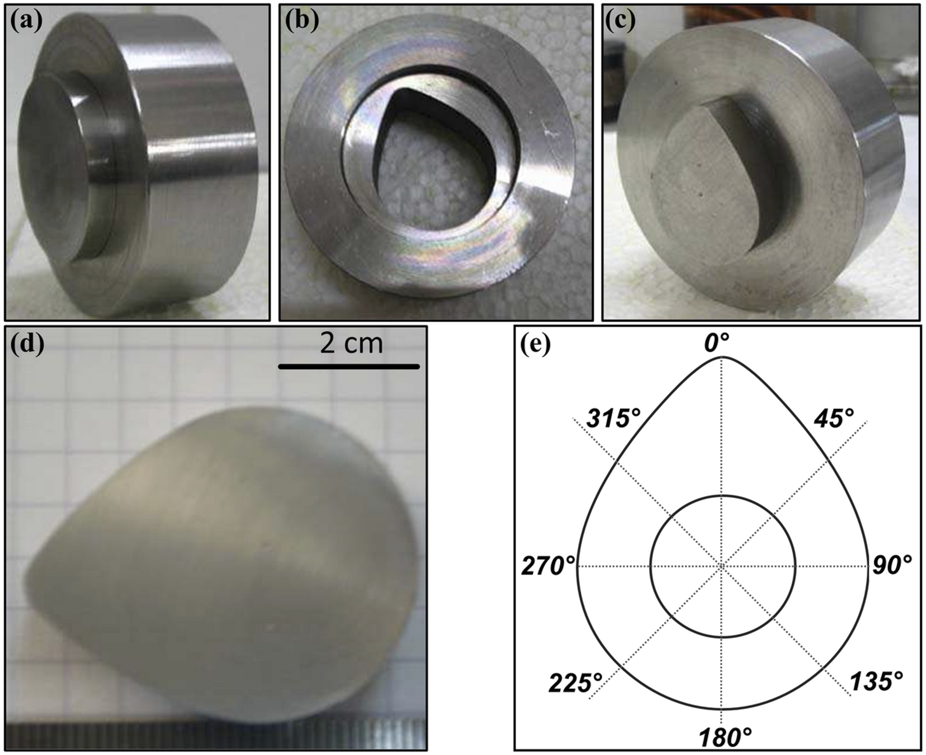
Regions on the cam profile are identified by angles from the top (0°), as shown in Figure 2(e). Using these classifications, physical features (e.g., roughness), before and after the tests, were correlated to the location on the cams.
Wear testing setup (dry/wet conditions)
The main components of the domestic wear testing setup comprise the engine, engine driver, shaft, flywheel, load unit (pressure shaft, spring, screws, weight holder, etc.), and oil tank, as shown in Figure 3. The rotation (rounds per minute, RPM) of the motor was controlled by an engine driver to either keep the rotation constant or to increase it steadily. A flywheel is used to prevent loss of torsion in case of power loss or unforeseen events during prolonged testing. The shaft is inserted into the cams, which were drilled post-manufacturing, and mechanically attached to the shafts in an assembled crankshaft fashion.
34
Domestic setup prepared for wear tests of cams in dry and wet conditions.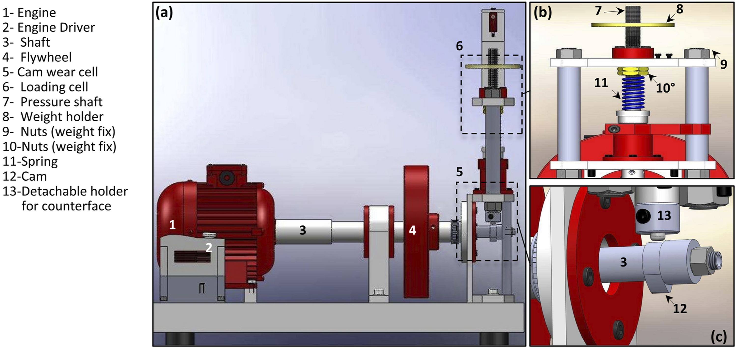
The loadcell in the setup (Figure 3(b)) is attached to a spring which can be tightened or loosened to control the force exerted on the cam. Further, the edge of the loading cell is designed to fix detachable bearings or pins, enabling different configurations for wear tests, as shown in Figure 3(c). In the current study, a bearing made of ORS® 6000 100Cr6 graded steel 35 was fixed which served as a non-moveable and non-rotating counterface.
In order to mimic the actual working conditions of the camshaft in an engine, an oil tank was attached to the setup. The internal structure of the oil tank is shown in Figure 4. The tank was filled with commercial (60 mlt DEW® SAE10W40) engine oil. An electrical heating device was used to heat the oil (to 90°C), and the temperature of the oil was continuously monitored with a thermocouple. Figure 4(c) shows that the cam dips in the oil once every rotation, ensuring completion of the wear tests under wet conditions. Inner structure of the oil tank for wear tests in wet conditions. (a) Side view, (b) transverse view and (c) actual setup image.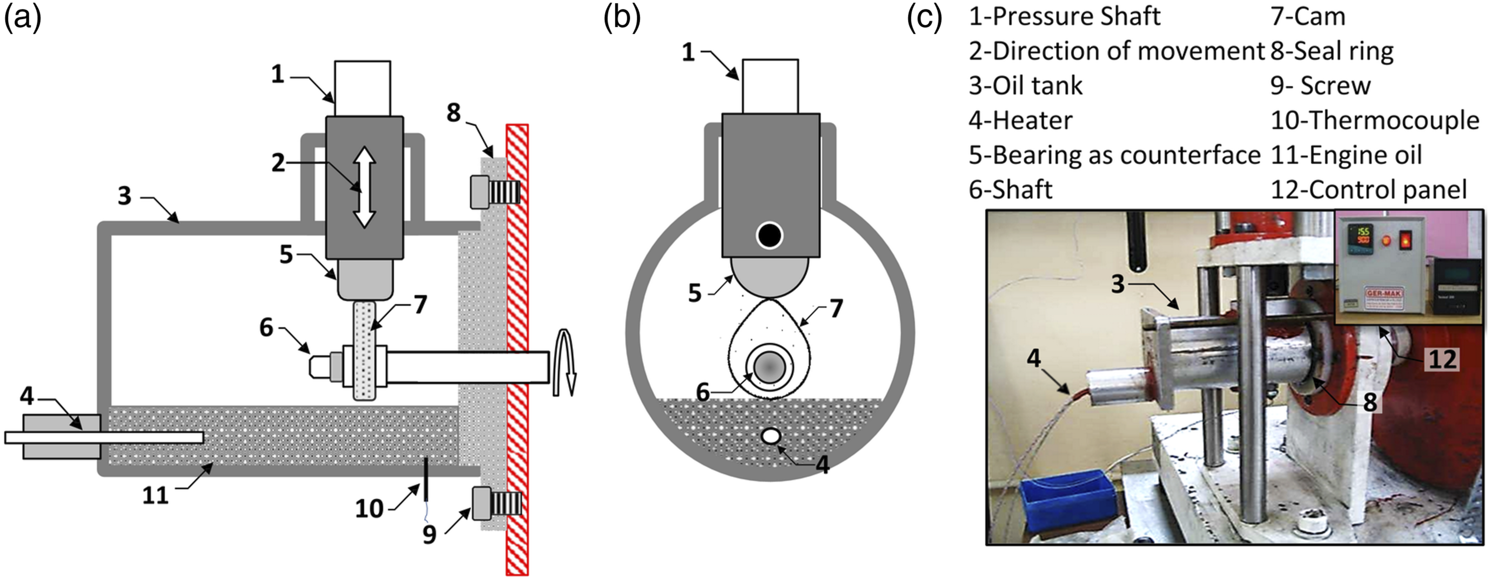
Operation principles
The working operation of the setup is as follows: the engine enforces rotational movement in the cam and the cam pushes the counterface after dipping in the heated oil. The RPM, force on the cam, and oil temperature can be controlled and monitored in real-time.
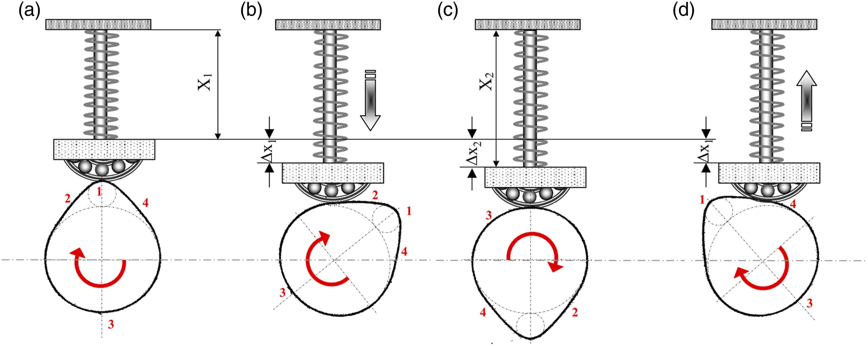
Different regions of the cam profile (Figures 1(a) and (b)) are exposed to varying forces while in contact with the counterface, as shown in Figure 5. While regions 1, 2, 3, and 4 are termed as cam nose, closing ramp, basic circle, and opening ramp-cam nose and basic circle are exposed to maximum and minimum loads, respectively. In order to measure the exact force, a calibrated spring (k = 1.2) was used. The total contact force on the cam is given by equation (1). Pressure shaft movement and spring compression with the rotational movement of the cams against the fixed bearings.
In order to increase the total load (F), additional weight is added (Figures 3(b) and 6(b)) to the already present weight of bearing (acting as a counterpart) and attachment mechanism. At this stage, the value of the Δx1 is measured, and the nuts are fixed at this compression (Figures 3(b) and 6(b)). This weight is known as dead weight (F1). Since the added weight is 5 kg and the weight of the setup is 1.95 kg, a total of F1 = (6.95) (9.98) N = 69.36 N is achieved. At this stage, the value of the comparator is set as zero, corresponding to region 4 (basic circle). Finally, when the shaft is driven by the engine, the spring is further compressed (pushed upwards, Figure 6(c)) by the cam, and a total load of F = 150 N is achieved. This compression value (Δx2) is measured by the comparator, which is attached to the pressure shaft shown in Figure 3(b). Finally, the value of F is calculated, correlated with the corresponding angles on the die (Figure 2(e)), and presented on the graph as shown in Figure 6(d). State of spring compression in loading cell at (a) no compression, (b) addition of 5 kg, (c) spring compression due to rotational movement of the cam. (d) Load profile corresponding to angles on cam.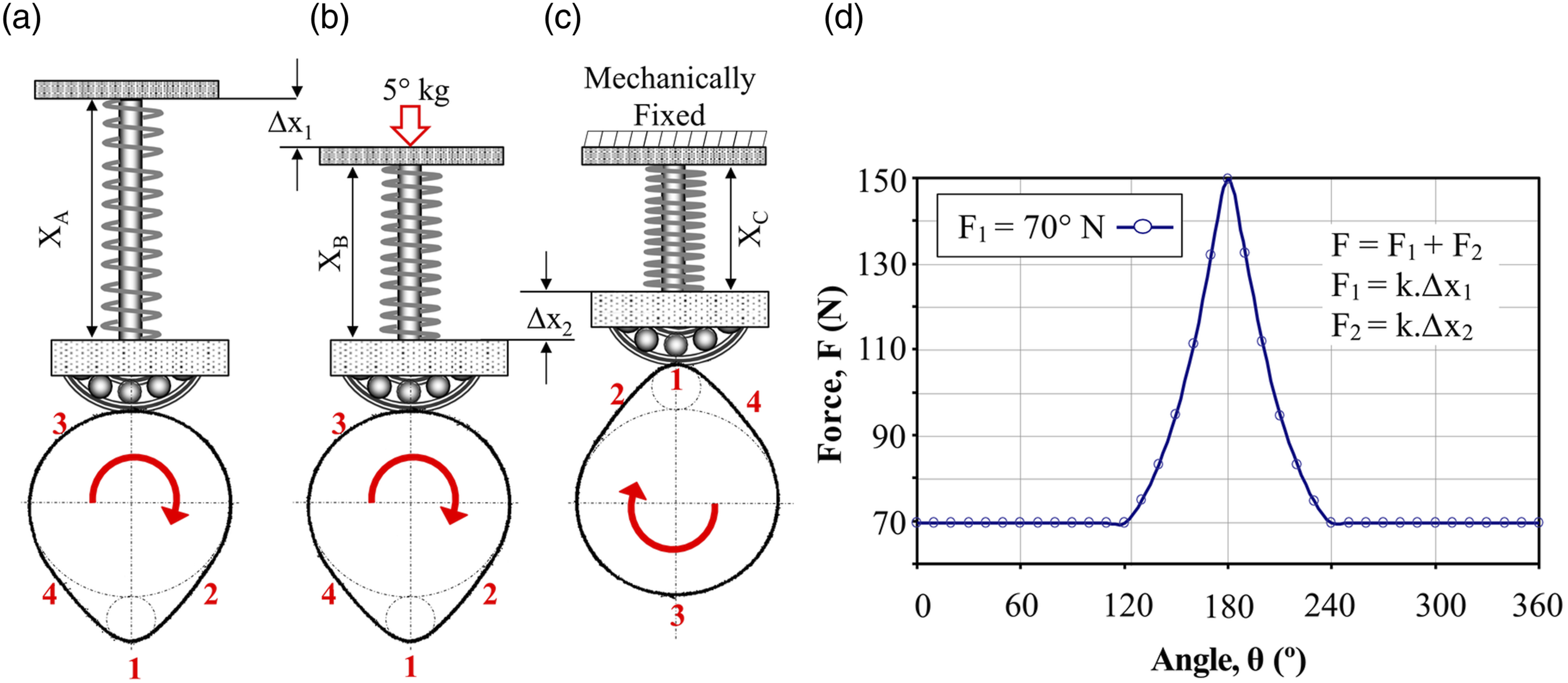
After the completion of the wear tests, all samples were again subjected to cleaning in a delubricant solution, followed by bathing in alcohol and water. Later, the roughness of the samples was measured with an increment of 45°C from the surfaces which were subjected to wear. The weight of the samples was measured with a precise simple mass balance (accuracy of 0.01% gr).
The wear rate (W) is measured by dividing the volume of the weight loss by the product of travel distance and the load. The sliding distance is measured by using RMP, the circumference of the cam, and the duration of the experiment. The wear resistance (WR) is calculated by taking the inverse of W, and the specific wear resistance (WRC) is calculated by further dividing the WR by the density of the specimen. So, the comparative analysis of different types of materials with different densities was accomplished by using WRC.
Microstructural analysis of cams
The surface of the cams was subjected to microstructural analysis using optical macroscope, scanning electron microscope (SEM, Leo 440 with EDX attachment), and X-ray diffraction (XRD, Panalytical-Empyrean). XRD device operated at 45kV and 40 mA with a Cu X-ray tube (λ = 0.15,406 nm). The microstructure of the various regions of the cams was analyzed after the wear tests under wet and dry conditions.
Results and discussion
The wear performance of the cams made of various Cps reinforced MMC is reported in both dry conditions as well as wet conditions in the artificial engine-like environment. Cams were subjected to a maximum force of 150 N at the tip, with a rotation speed of 500 r/min for 150 minutes (2.5 h).
Wear tests under dry conditions
Figure 7 shows the wear rate (W) and specific wear resistance (WSR) of the specimens after wear tests in dry conditions. While the wear behavior of the composite cams was similar, the cam made of nodular graphite cast iron exhibited maximum wear resistance. The test for reference AA2124 cam could not complete as it adhered to the counterface for being ductile before the test could reach a total exposure time of 150 minutes. The wear resistance of the MMC cams increased linearly till the fraction of the Cps reached 20 vol.%.
32
Later, while the trend in the increase was diminished for smaller Cps (B4C: 1–7 μm, SiC: 2 μm), it reversed for larger Cps (SiC: 20 μm). (a) Wear rate and (b) specific wear resistance of cams based on MMC composites and nodular graphite cast iron.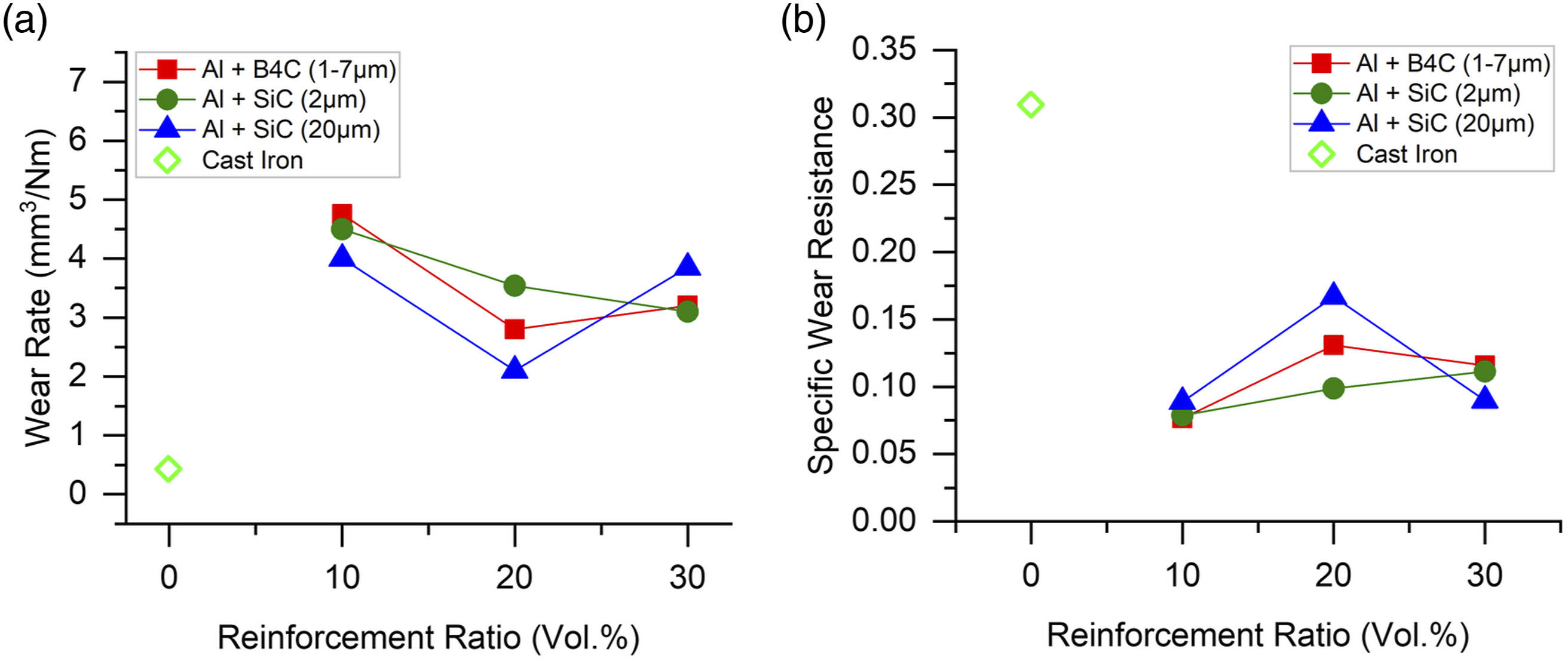
Figure 8 shows the influence of wear tests under dry conditions on the overall shape of the cams and counterface for Al+10%B4C. The surface of the cam can be characterized by plastic deformation at various regions (Figures 8(a) to (c)). The surface of the counterface shows the presence of material buildup which transferred from the cam to the counterface, as shown in Figure 8(d). The reason behind that is the low content of the Cps (only 10 vol. % B4C) as well as the ductility of the Al matrix. The influence of increased B4C content (Al+30%B4C) on the worn surfaces of the cams and counterface is shown in Figure 9. While the surface of the cams shows wear scratches (Figures 9(a) to (c)), the material buildup witnessed for Al+10%B4C is absent for Al+30%B4C, as shown in Figure 9(d). The absence of the built-up edges can be attributed to the higher content of the B4C particle, which hindered the disassociation of the B4C and Al matrix. (a, b, c) Macrographs of the surface of different regions of Al+10 vol.% B4C, (d) surface of the counterface, and (e) nomenclature of different regions of cam (sd: Sliding direction). (a, b, c) Macrographs of the surface of different regions of Al+30 vol.% B4C, (d) surface of the counterface, and (e) nomenclature of different regions of cam (sd: Sliding direction).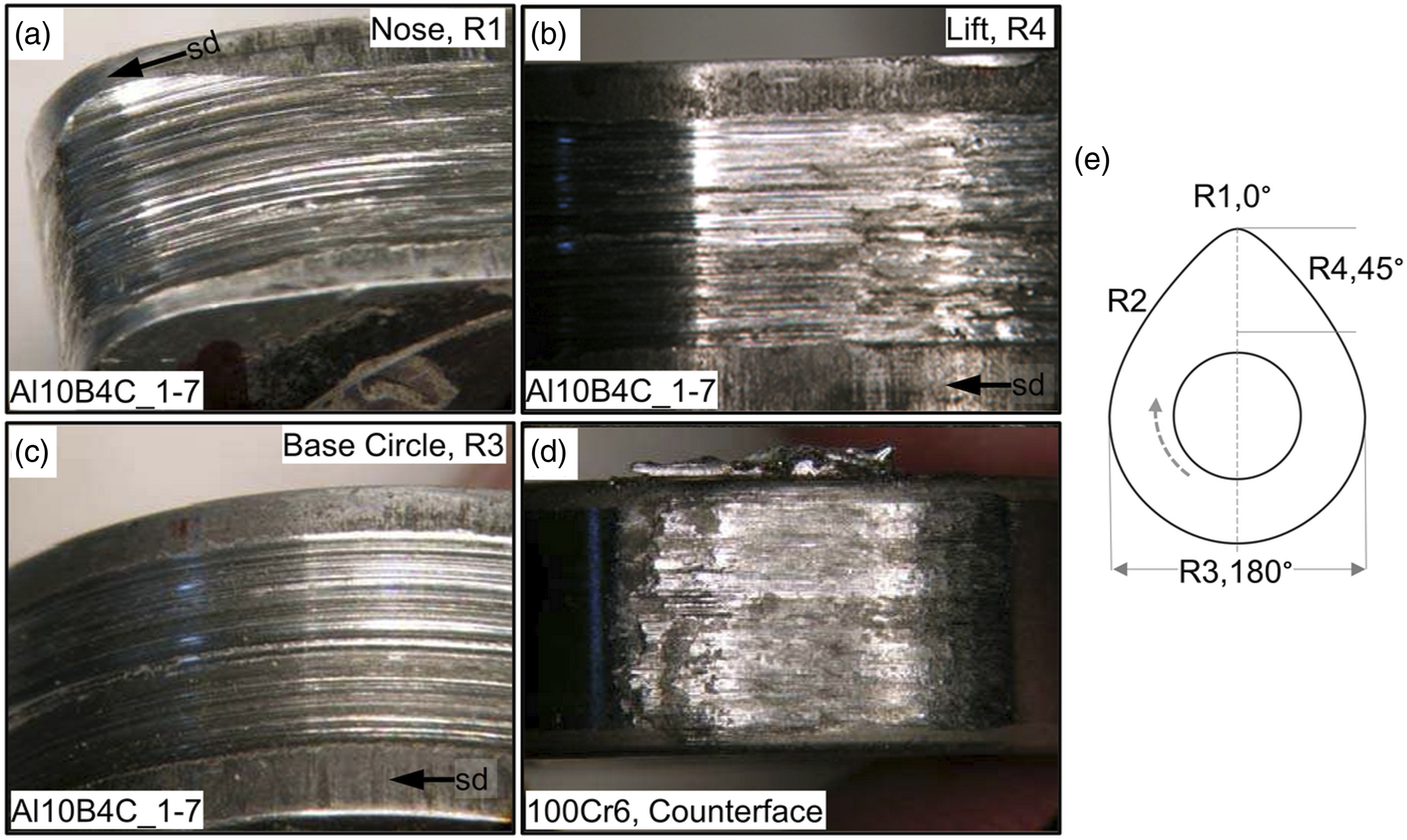
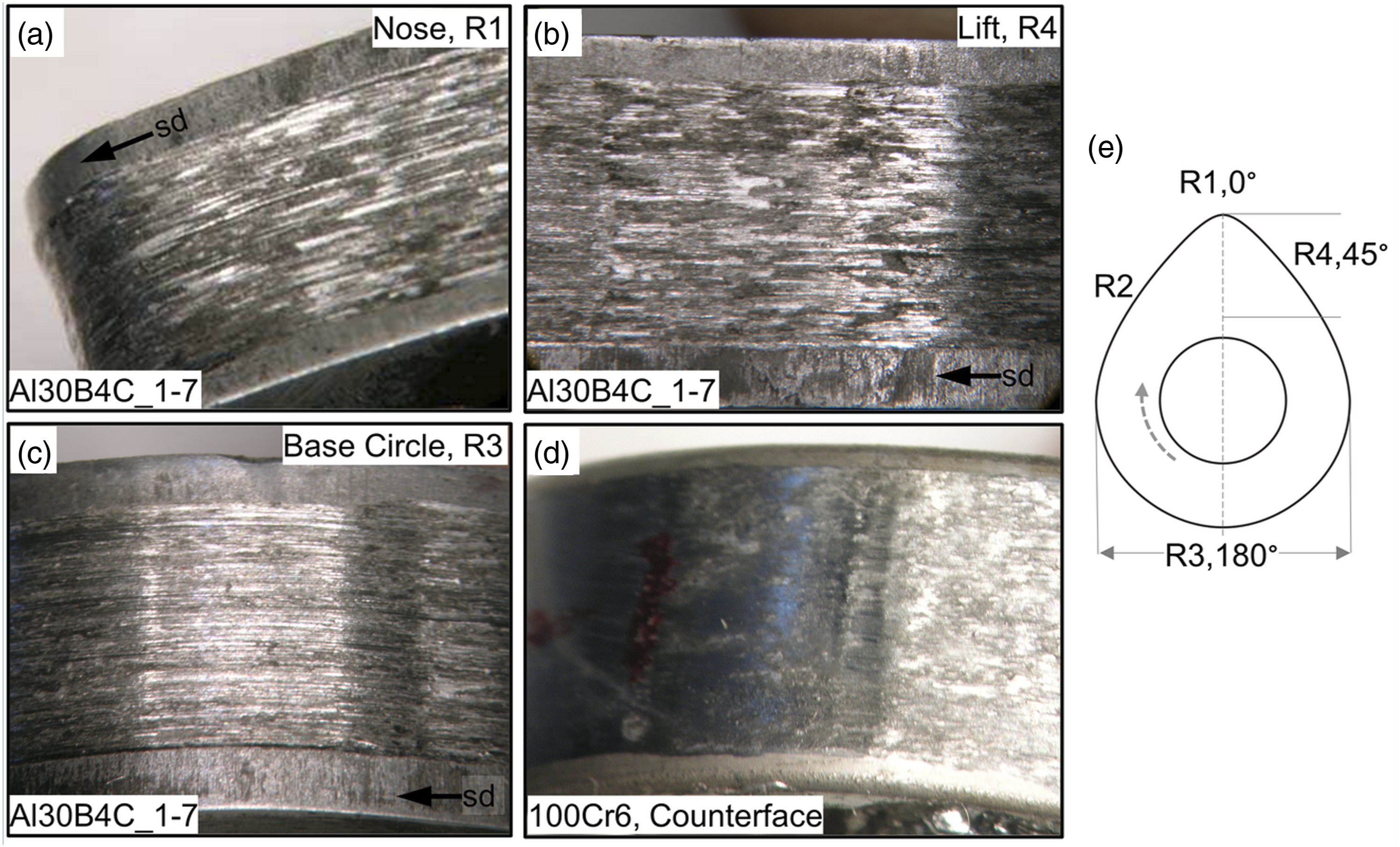
However, although moving from 10% B4C to 20%B4C reduced the wear rate and improved the wear resistance of the cams (graphs in Figure 7), the wear resistance slightly decreased for 30%B4C. This is because the higher fraction of freed B4C particles act as abrasives and cause material loss in cams. Since the mode of wear transfers from scuffing and galling to three body abrasive wear, the surface of the counterface lacks material buildups, as shown in Figure 9(d), and the wear resistance slightly decreases.
The morphology of R1 (nose) of the Al+10%B4C and Al+30%B4C cams is shown by SEM images in Figures 10(a) and (b), respectively. The ductile nature of the Al matrix and the lower B4C content resulted in a visually noticeable material loss in the Al+10%B4C. Additionally, R1 (nose) and R4 (lift) show sliding-wear-induced scratches with the presence of a distinct boundary line between R1 and R4. Since R1 and R4 act against the load imposed by the spring, they are most prone to wear. In order to quantify the increase in the roughness of all the regions (R1 to R4, shown in Figure 10(e)), the percentage increase in the roughness values of these regions is shown for Al+10%B4C and Al+30%B4C. Due to the abrasive characteristics and higher content of freed B4C particles, the roughness of the Al+30%B4C is slightly higher than the Al+10%B4C cams. Also, the roughness of R4 and R1 is higher within the cams since they are exposed to higher loads during wearing. Burdzik et al.
21
also reported region-dependent wear of the cams during dry-wear experiments. SEM images of the nose microstructure and surface roughness of various regions in (a, c) Al+10 vol.% B4C and (b, d) Al+30 vol.% B4C. (e) Nomenclature of different regions of cam (sd: Sliding direction).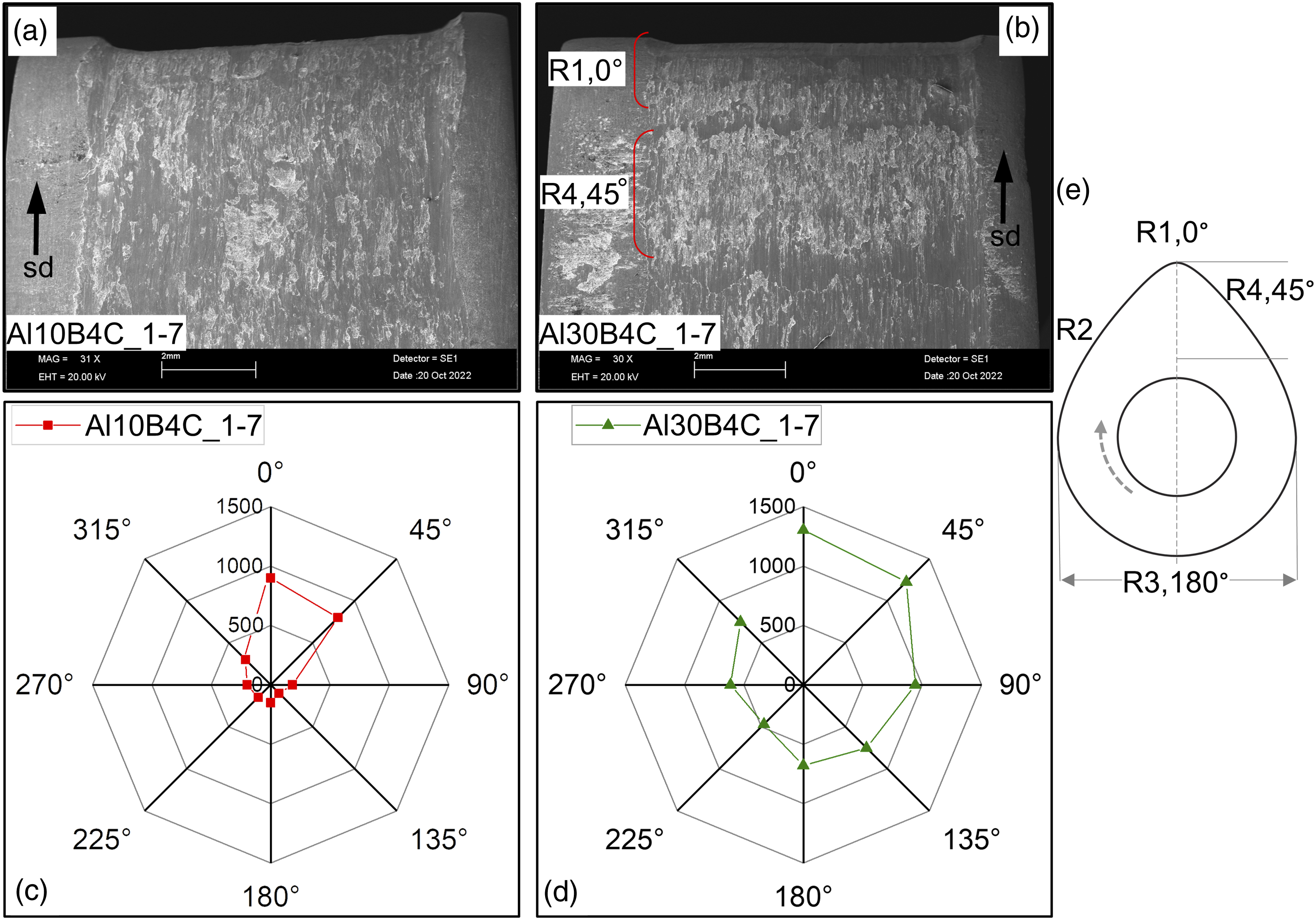
Figure 11 shows that some regions in the Al+30%B4C specimen are resolidified after melting under dry conditions. This is due to the conduction of experiments in dry conditions, extended duration of wear tests, and increase in temperature due to frictional forces.
36
Due to the melting and solidification cycle, the surface is characterized by thermally induced cracks (Figure 11(b)) during the cooling process. Additionally, the XRD analysis (Figure 11(c)) of the region of interest (white rectangle in Figure 11(b)) shows the presence of oxides and Cr. The oxides are formed during solidification and Cr is transferred from the steel counterface to the cam. (a), (b) Microstructure of Al+30%B4C based cams after melting and re-solidification. (c) XRD analysis of the resolidified region. (sd: Sliding direction).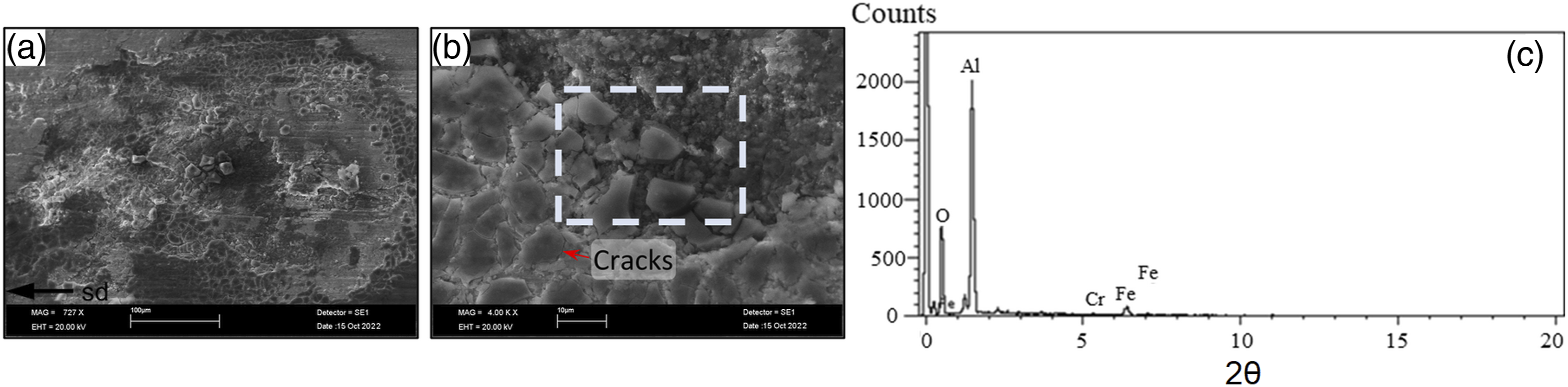
The post-wear cam and the counterface profiles of Al30SiC_2 are shown in Figure 12. The wear resistance of Al30SiC_2 composite cam increases with increasing reinforcement ratios, as shown in Figure 7(b). Due to smaller Cps acting as reinforcement,
37
neither R1 (nose) in the cam nor the counterface contains deep grooves or wear traces (Figures 12(a) and (b)). This also is the reason that the percentage increase in the roughness for the 2 μm SiC-based composites is lower compared to 1–7 μm B4C based composites (compare Figures 12(c) and (d) with Figures 10(c) and (d)). Macrograph of the nose (R1) for (a) Al+30 vol.% SiC cams and (b) counterface. (c), (d) Increase in the surface roughness with increasing reinforcement ratios, and (e) nomenclature of different regions of cam. (sd: Sliding direction).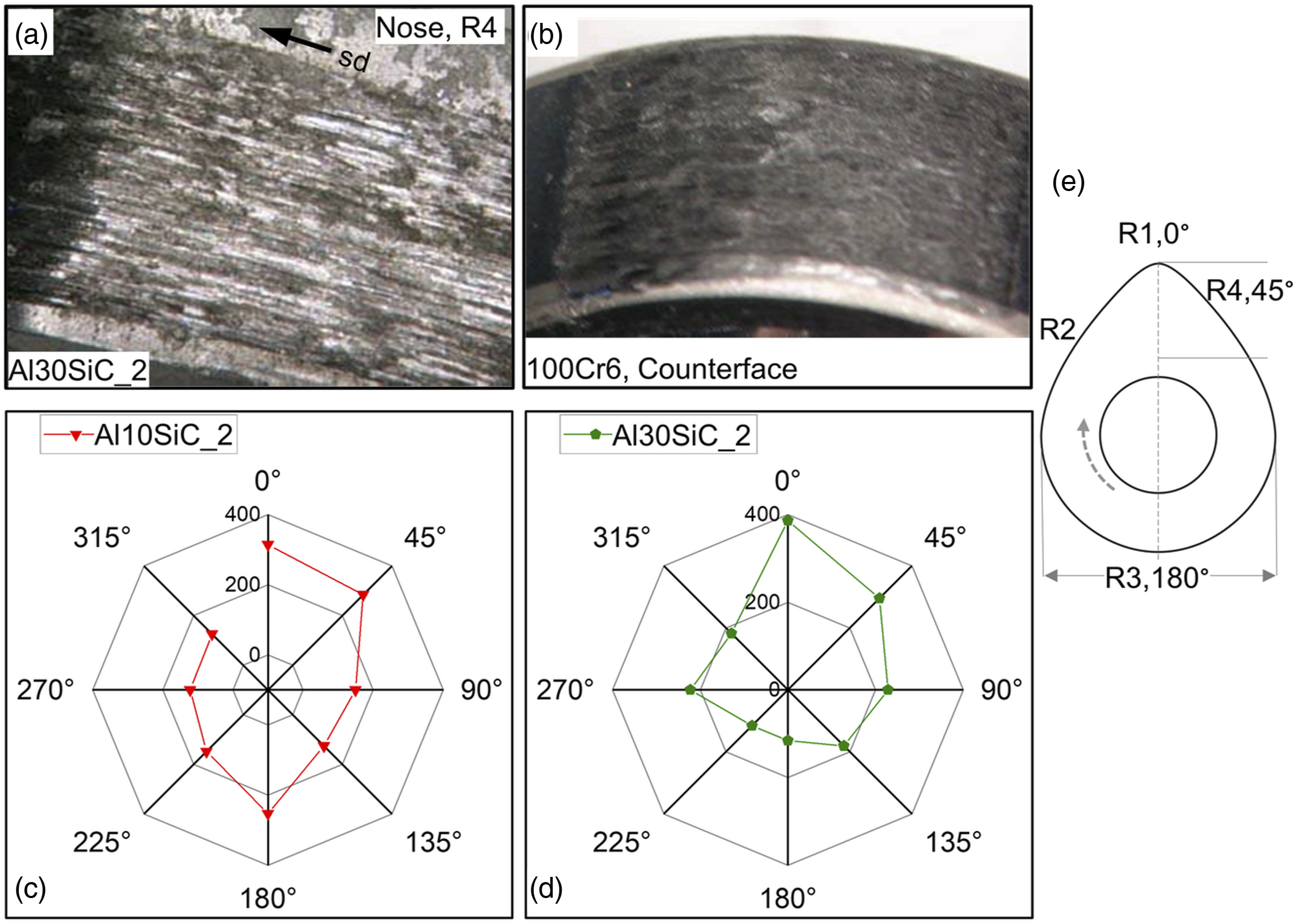
The SEM analysis of the R1 (nose) in the Al30SiC_2 specimen reveals the smearing of the FeO and Al2O3 on the SiC particles (Figure 13). These SiC particles are exposed after the peeling of the Al layers during wear. The oxides are formed due to material transfer from the counterface to cams and high temperatures. Since there occurs a shift in the load values between R1 and R2, material buildups at the inter-region boundaries, due to friction shifts in the ploughed areas, can be witnessed (Figure 13(b)). SEM images of Al30SiC_2 after dry wear tests. (a) Oxidation due to elevated temperatures, (b) material buildup at inter-region boundaries, and (c), (d) particle agglomeration in the pits. (sd: Sliding direction).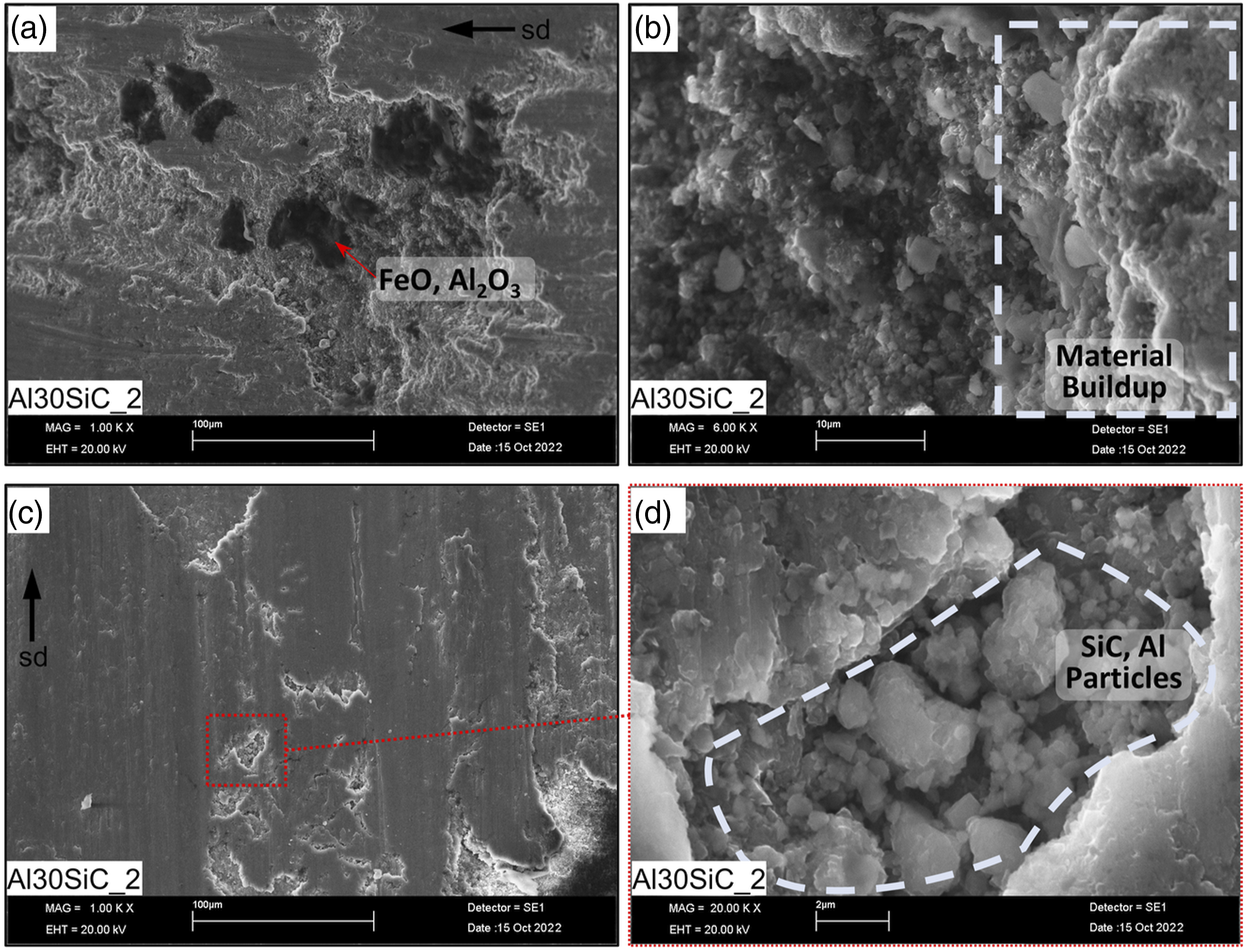
The top layer of the cams is cold-worked and hardened during the initial stages of the experiments due to applied loads. As the experiment propagates, the top surface is peeled, and there are formed pits on the surface, as shown in Figure 13(c). The smaller size of the SiC particles for the Al30SiC_2 cams assists in the accumulation of SiC particles in the pits of swollen Al matrix (Figure 13(d)). Thus, the three-body abrasive character of the SiC particles is diminished. This also explains the lower material loss for cams reinforced with 2 μm SiC as shown in the graphs of Figure 7.
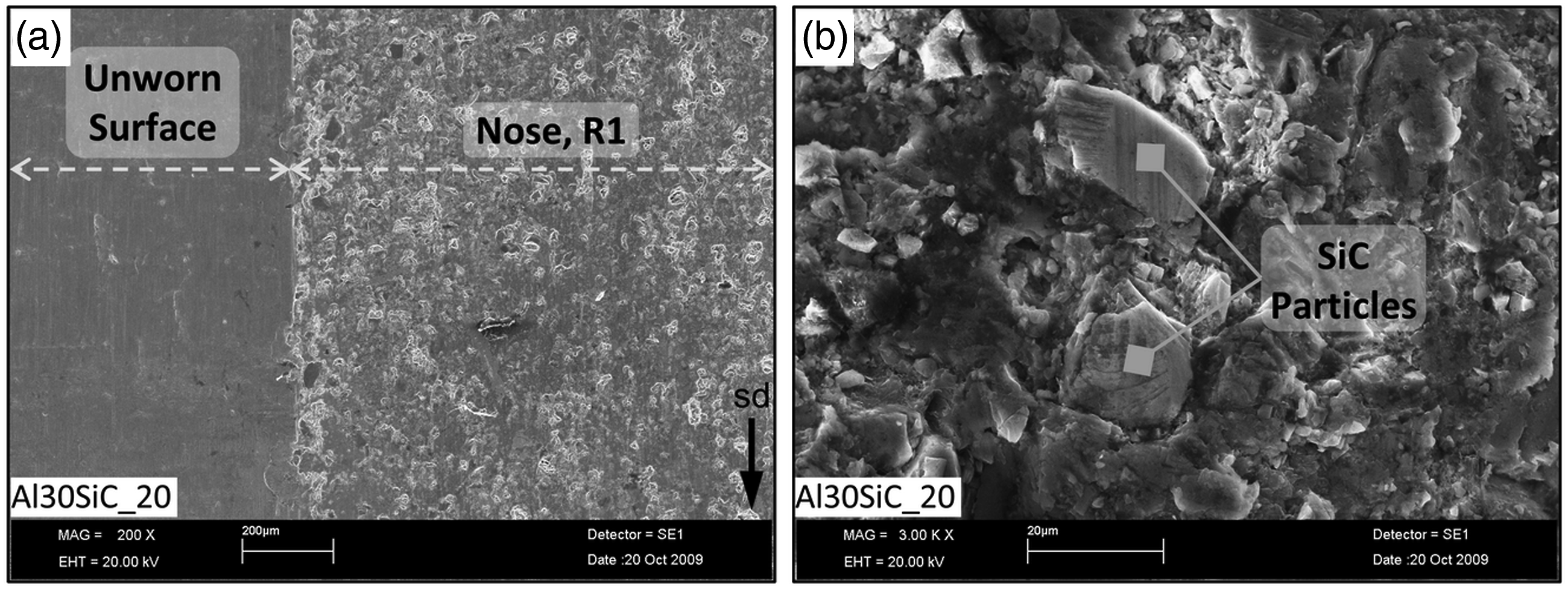
For the Al matrix cams in which larger (20 μm) SiC particles are used as reinforcement, the surface of the cam and counterface is shown in Figure 14. Both interacting surfaces show wear traces parallel to the sliding direction. Figures 14(c) and (d) show an increase in the roughness of various regions on the cam for Al10SiC_20 and Al30SiC_20 specimens, respectively. While there is a slight increase in the roughness as the content of Cps increases, the percentage increase in the surface roughness is clearly higher for cams reinforced with 20 μm SiC Cps (Figures 14(c) and (d)) than the cams reinforced with 2 μm SiC Cps (Figures 12(c) and (d)). Macrograph of the R1 (nose) for (a) Al30SiC_20 cams and (b) counterface. (c), (d) Increase in the surface roughness with increasing reinforcement ratios, and (e) nomenclature of different regions of cam (sd: Sliding direction).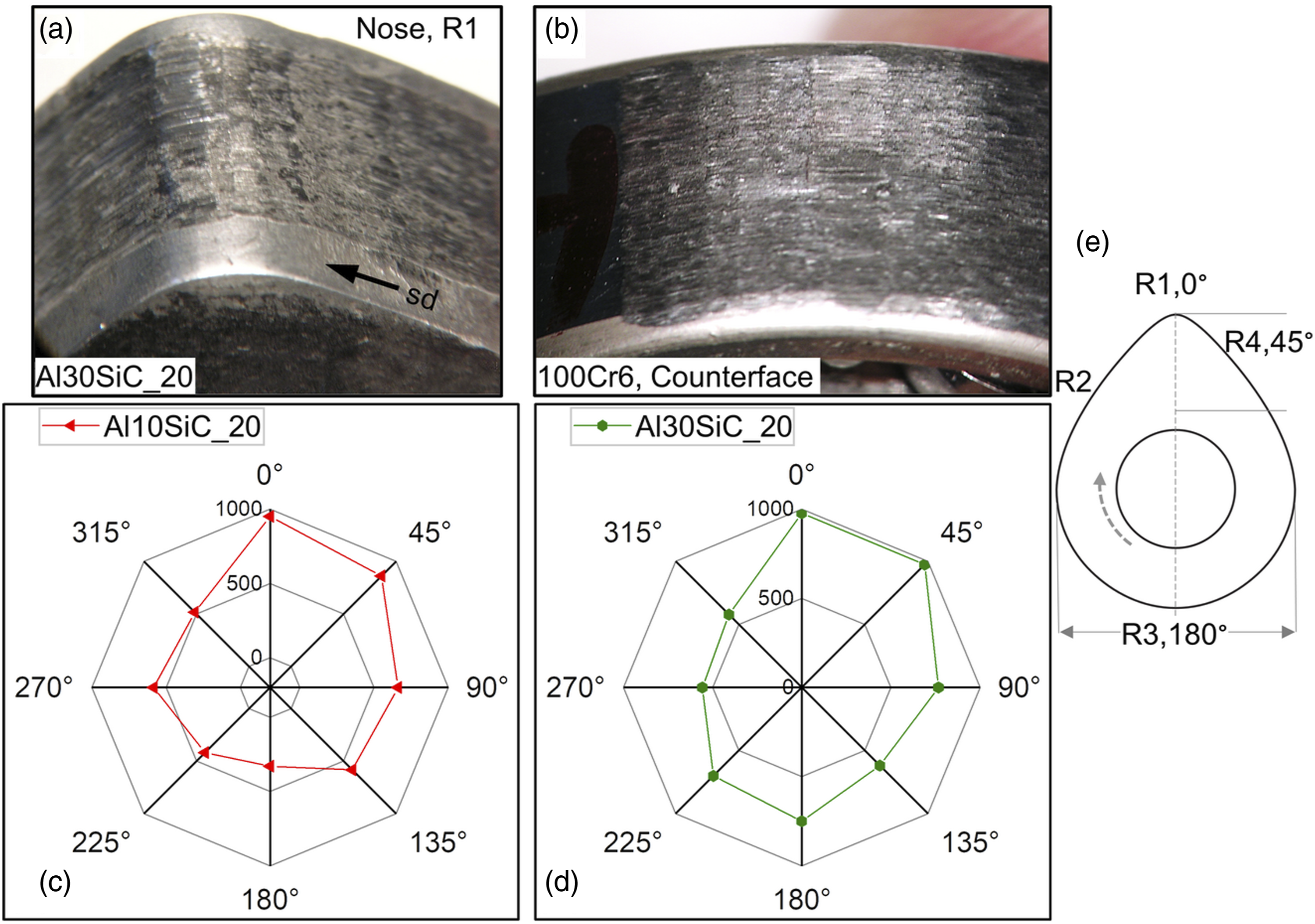
In order to further understand the influence of increasing the SiC particle size on the wearing of the cams, Figure 15 compares various features of the Al30SiC_2 and Al30SiC_20. Clearly, using larger (20 μm) SiC particles causes more significant wear scratches to be formed on the surface (compare Figure 15(b) with Figure 15(c)).
38
Such scratches are only noticeable in the worn areas which were in contact with the counterface (Figure 15(a)). Comparison of microstructure at the nose (R1) of the Al+30 vol.% SiC cams by using (a), (b) 2 μm and (c), (d) 20 μm SiC size as reinforcement (sd: Sliding direction).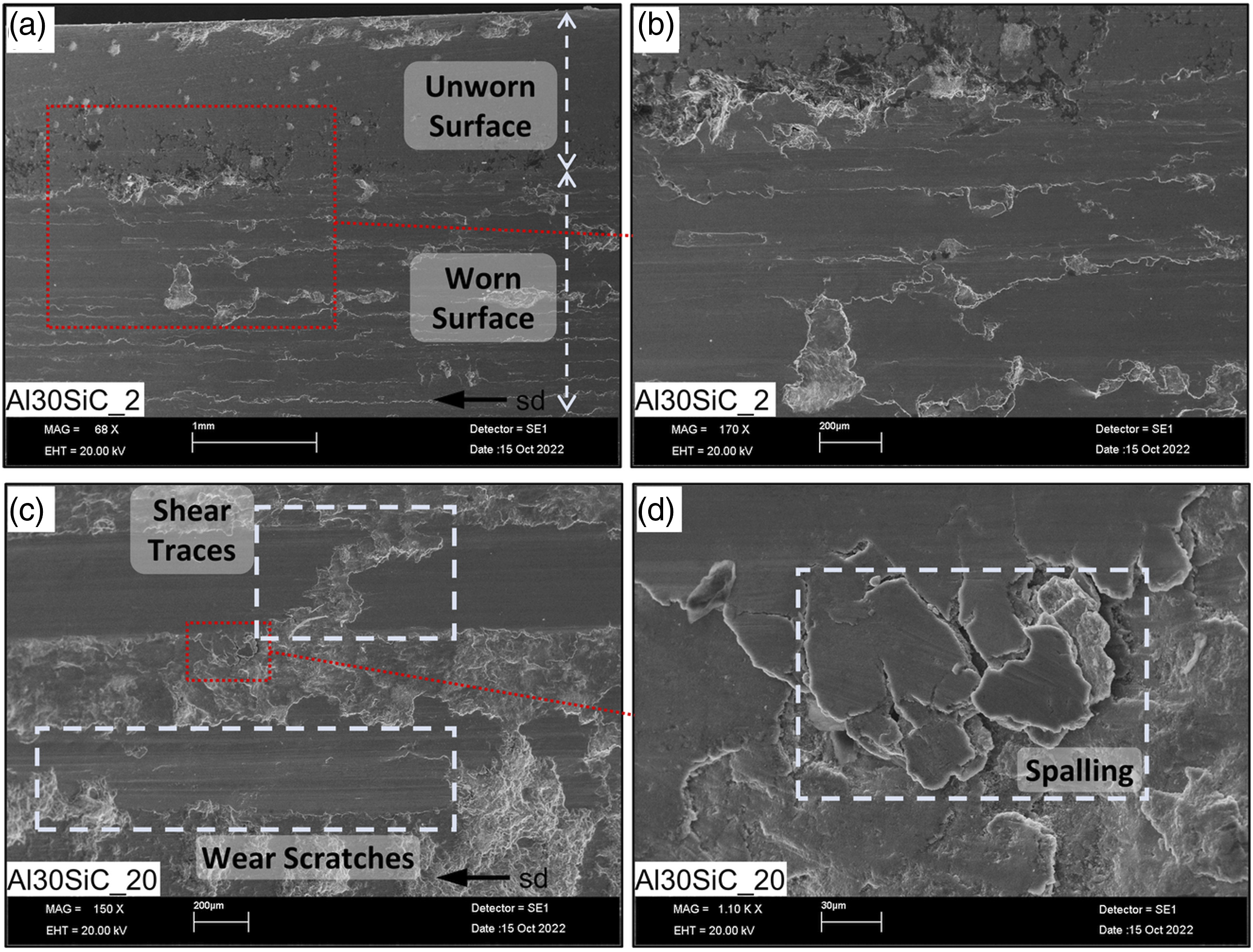
At the initial stages of the wearing process, a cold-worked hard surface is attained, which is subjected to shear stresses due to continuously repeating sliding loads. Such load conditions cause the hardened surface to develop cracks which are characteristic of shear stresses, as shown in Figure 15(c). 39 As the wear test continuous, these cracks are deepened and widened depending on the fraction and size of the Cps which are scooped off at the later stages of the experiment. Furthermore, the hardened surface is subjected to fatigue-induced surface-to-subsurface spalling, as shown in Figure 15(d). 40 Various authors such as Das et al. 36 and Axen et al. 33 have reported the existence of a critical value of the abrasive size after which the wear resistance decreases for the MMCs. Jamaati et al. 41 reported that the role of spalling for degraded wear resistance is much more severe than the improvement in the wear resistance due to the presence of Cps in the Al-based Cps reinforced MMCs. So, the combined influence of these phenomena results in larger material loss and lower wear resistance for the Al+30%SiC cams, which are reinforced with larger (20 μm) SiC particles.
Wear tests under wet conditions
Similar to dry conditions, Figure 16 shows the wear rate (W) and specific wear resistance (WSR) of the specimens after wear tests in wet conditions. Contrary to dry conditions, neither AA2124 nor NGCI reference cams failed to complete the wear tests under wet conditions. (a) Wear rate and (b) specific wear resistance of the cams under wet conditions.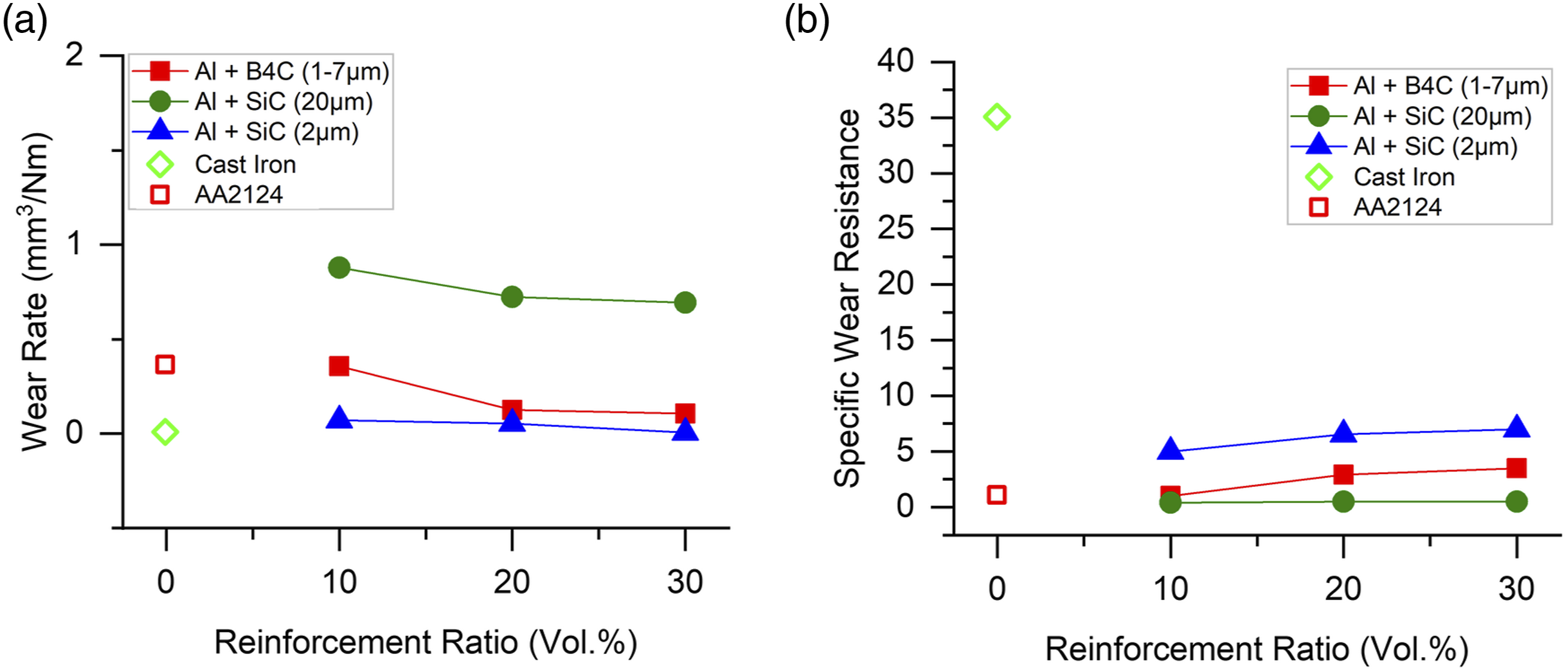
Using ceramic particles as reinforcement in the Al reduces the wear loss with increasing reinforcement ratios (Figure 16(a)) as compared to the reference AA2124 matrix. 16 The Fe-based NGCI, however, still outperforms both; the cams made of merely AA2124 matrix and Cp reinforced composites. For a better comparative analysis, the specific wear resistance of all types of cams is shown in Figure 16(b) by dividing the wear resistance by the density of the cams. Here too, the trend is not disrupted, and improvement in the wear resistance is consistent with the increasing reinforcement ratios for composite cams.
Figure 17 shows that the wear scratches associated with the wear under dry conditions (presented in Figure 9(b)) are absent for the Al30B4C_1–7 specimens in wet conditions. Sliding wear character appears to be much more dominant than abrasive wear due to the presence of engine oil and smaller Cps particles.
42
Furthermore, the increase in the roughness of the surface of the cam is significantly lower compared to wear under dry conditions for the same type of specimens (compare Figure 17(b) with Figure 10(d)). A diminished increase in the surface roughness can be associated with the reduced abrasive character of the B4C particles due to the presence of the lubricant or due to the adhesion of the scooped-off B4C particles back to the Al matrix on the cams or to the counterface. (a) Surface of the nose (R1) and lift (R4) for Al+ 30 vol.% B4C cam and (b), (c) percentage increase in the surface roughness for (c) various regions on the cam (sd: Sliding direction).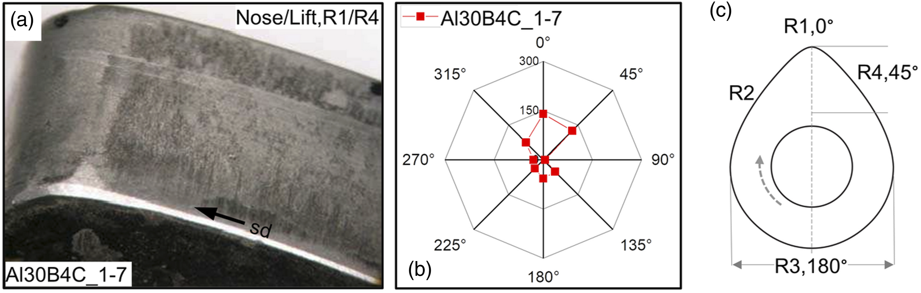
Further analysis of the Al30B4C_1–7 with SEM reveals the absence of deep grooves parallel to wear directions (Figure 18). While the R1 (nose) contains sliding wear traces (Figure 18(a)), R4 (lift) is characterized by a ploughing mode of wear (Figure 18(b)). Instead of delamination, peeling, or cutting, there are formed pits in which the B4C particles are embedded (Figures 18(c) and (d)). Despite extended wear experiments, the presence of B4C particles in the spalled regions points out an adequate bonding between the B4C particles and the Al matrix. Bingley et al.
43
reported that the surface roughness of the mild and stainless steel showed lower roughness during the three-body abrasive tests under wet conditions. The surface was characterized with deep grooves in case of dry wear, similar to observations of this study and the overall surface features mostly depended on the hardness of the tested materials. SEM micrographs of the Al+30 vol.% B4C cam after the wear tests under wet conditions. (a), (b) Formation of ploughed surface and (c), (d) pits can be seen (sd: Sliding direction).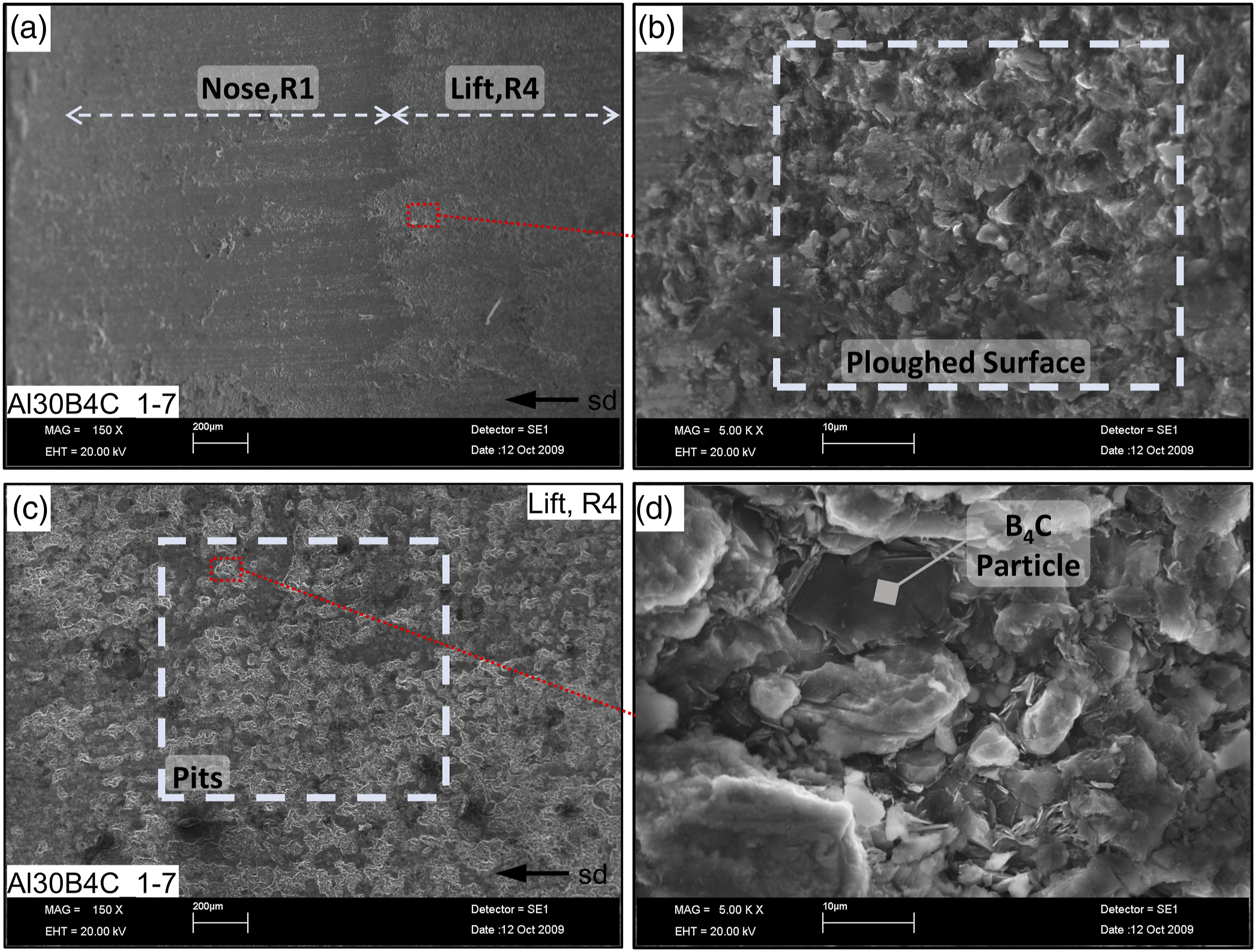
The appearance of the Nose (R1) and lift (R4) for Al30SiC_20 specimens is shown in Figure 19(a). Surfaces in these regions are characterized by sliding wear traces which show a roughness value lower than the dry conditions of the same specimen. However, the grooves formed are slightly deeper than the Al30B4C_1–7 because of the presence of the 20 μm Cps. During the wear tests of the cams under wet conditions, the initial stage is based on the sliding wear of the cams, for which the intensity depends on the regions of the cams. Due to the presence of the engine oil, initially, plastic deformation or cutting-type wear is not witnessed. As the process continues, the Al matrix of the cams is worn off, and SiC particles are released. These hard ceramic particles act as third-body abrasives, and unlike the dry conditions, instead of shooting away, these particles stick to the cam/counterface regions due to the presence of viscous engine oil. Prolonged wear at this stage results in the wearing of the cam or the counterface, depending on the hardness. However, since the cam surface contains a ductile Al matrix, the abrasive particles might have a chance to embed back into the matrix. This is the reason Al30SiC_20 cams contain SiC particles in the ploughed regions, as shown in Figures 20(a) and (b). (a) Surface of the nose (R1) and lift (R4) for Al+ 30 vol.% SiC cam and (b, c) percentage increase in the surface roughness for (c) various regions on the cam (sd: Sliding direction). Microstructure of the Al+30 vol.% SiC. (a) Comparison between unworn and worn (nose, R1) surfaces and (b) embedding of SiC particles in the pits of ploughed surfaces (sd: Sliding direction).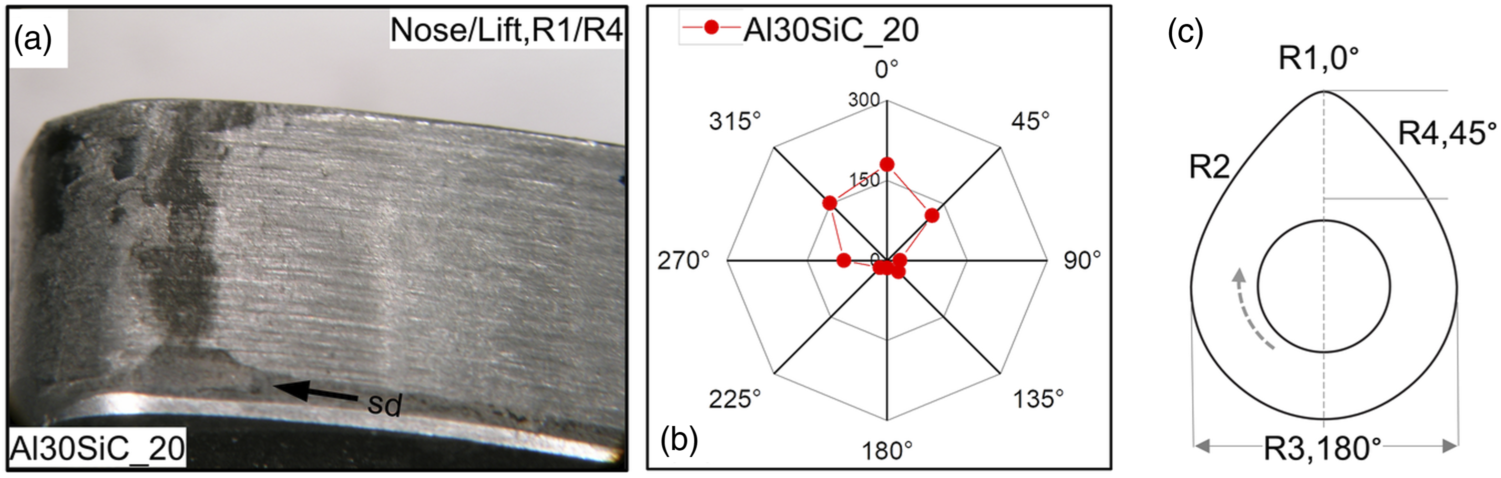
Post-wear profile comparison under wet/dry conditions
Unlike the wear tests in dry conditions and contrary to the surfaces of the cams, the surfaces of counterfaces are severely worn under wet conditions. Figure 21 compares the counterface surface, which are worn against Al30B4C_1–7 (Figure 21(a)) and Al30SiC_20 (Figure 21(b)) in both dry and wet conditions. Clearly, the specimens reinforced with 20 μm ceramic particles severely wear the counterfaces. Comparison between the wearing of the counterfaces after wearing in wet and dry conditions against (a) Al30B4C_1–7 and (b) Al30SiC_20. (c), (d) Transverse view of the worn counterfaces.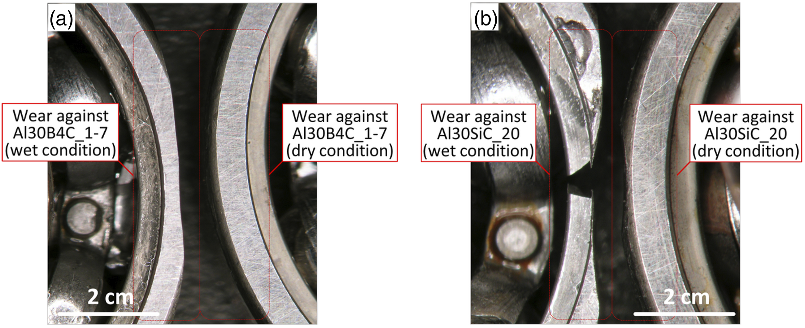
Bingley et al.
43
studied the influence of abrasion of mild and stainless steel under wet and dry conditions. They reported that the larger ceramic particles under wet conditions promoted the cutting mechanism of abrasion along with the sliding and repeated deformation. The presence of oil, which is enriched continuously with the freed SiC particles, and the profile of the cam assist in reintroducing the ceramic particles already worn away and mixed in the oil tank back to the wear system. Such situations further enhance the wear in the counterface but do not majorly influence the wear of the cams since the SiC particles can be re-embedded back to the Al matrix in the cam. The SEM analysis of the counterface surfaces for Al30B4C_1–7 and Al30SiC_20 specimens (Figure 22) reveal the presence of cutting grooves which are in proportion with the size of the ceramic reinforcements used in the cams. Comparison between the abrasive wear scratches formed on the counterface after wet wearing against (a) Al30B4C_1–7 (smaller Cps) and (b) Al30SiC_20 (larger Cps).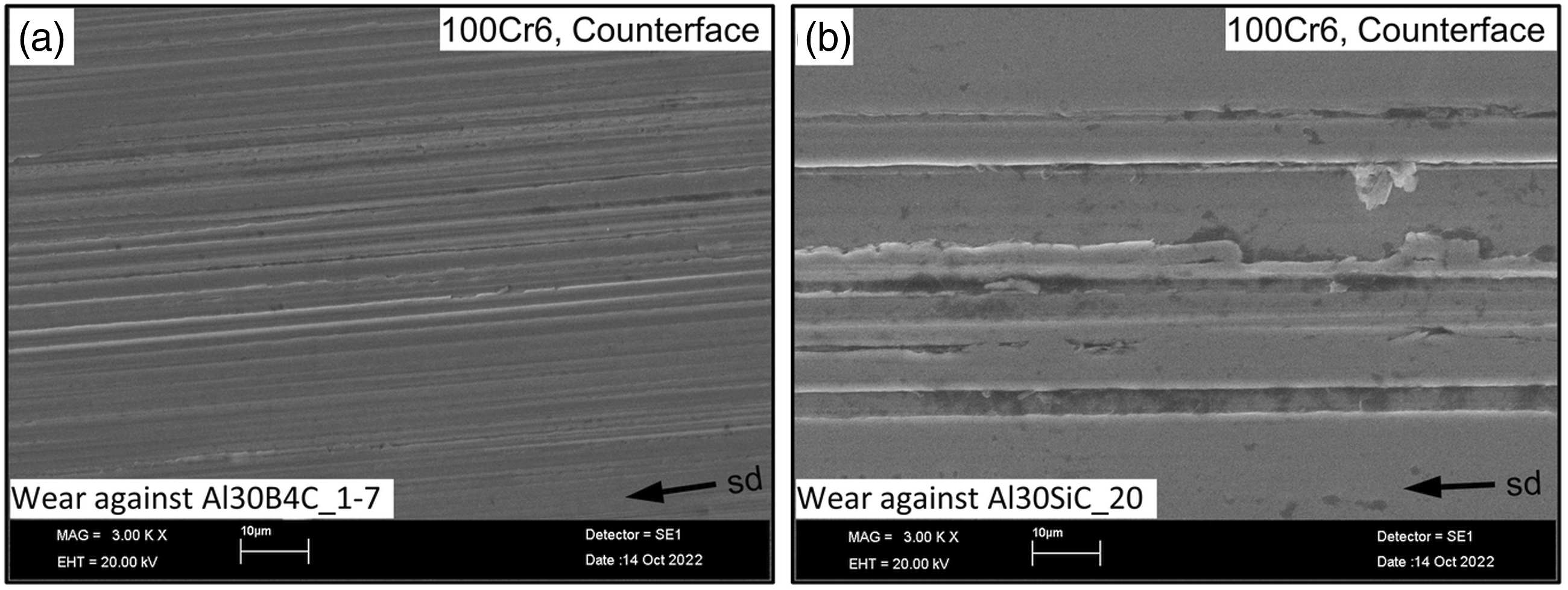
Conclusions
This study analyzes the feasibility of the ceramic particles reinforced Al matrix cams as integral engine parts by studying the dry and wet wear response using a domestically designed controlled wear setup. The following conclusions from the study can be deduced. • It can be concluded that proposed parameters (300 MPa, 615°C, 30 minutes) are suitable for the manufacturing of commercial Al-B4C and Al-SiC cams with highly accurate profiles without requiring further machining. • The wear extent in the MMC cams was considerably location-dependent; for example, the nose (tip of the cam) and the lift (region of the cam which pushes the piston spring) are most vulnerable to wear as compared to other regions on the cam. • Increasing the content of the ceramic particles results in higher wear resistance in dry conditions, except for the cams reinforced with the larger particles (20 μm compared to 2 μm). Here, freed SiC particles act as abrasives and reduce the wear resistance of cams under dry conditions. Under wet conditions, such freed particles are unable to hurl away due to the presence of viscous oil. • The repeating rotation of the cams assists in reintroducing the worn ceramic particles mixed in the oil tank back into the system. Such a situation results in severe weight loss in the counterface, especially for ultimate reinforcement ratios (30 vol.%) and larger ceramic particles (20 μm).
Footnotes
Declaration of conflicting interests
The author(s) declared no potential conflicts of interest with respect to the research, authorship, and/or publication of this article.
Funding
The author(s) disclosed receipt of the following financial support for the research, authorship, and/or publication of this article: The authors are grateful for the financial support of the Erciyes University Scientific Research Projects Coordination Unit, grant number FBT07-55, and the Scientific and Technological Research Council of Türkiye (TUBITAK), grant number 106M021.