
Abstract
Onset Theory (previously known as Strain Invariant Failure Theory) is a physics-based composite failure criterion attempting to predict failure at the level of constituents rather than for a homogenized ply. Applying Onset Theory correctly requires a number of steps. As a starting point for other researchers, a consistent approach is developed by resolving contradictions found in literature. This includes the micromechanical FEA process used to determine the individual fiber and matrix strains, such as correct choice of representative volume elements (RVEs), the use of transformed RVEs, boundary conditions, and the location of data extraction points. Analytical expressions are provided to determine the full state of strain in a ply, including in-plane and out-of-plane Poisson’s strains and thermally induced mechanical strains. Literature definitions of the critical invariants are discussed, and a trend in critical distortional invariants is observed. Assumptions and limitations of the theory are identified. Finally, a failure envelope is compared to World Wide Failure Exercise test data.
Keywords
Introduction
In 2001, Onset Theory was proposed in ref. 1 as Strain Invariant Failure Theory (SIFT). It attempts to predict failure at the constituent (fiber and matrix) level rather than for a homogenized ply. It was further developed in refs. 2, 3, and 4. Ref. 5 gives an overview of SIFT, including the choices made during development.
Many authors have published various versions of Onset Theory. This article provides a summarized, consistent approach to Onset Theory as a starting point for other researchers. Recently, ref. 6 had similar intent, but different focus. It is referenced where appropriate. This article provides additional insight, in particular how to determine the full state of strain (including thermally induced mechanical strains) analytically, and how to draw in-plane failure envelopes. Familiarity with the articles mentioned above is assumed, in particular regarding micromechanical enhancement (MME).
Onset Theory requires determining the homogenized state of strain of the laminate under combined loading (see Homogenized State of Strain ), converting it to the dehomogenized constituent strains for each ply (see Micromechanical Enhancement (MME) ), and calculating the first invariant and second deviatoric invariant of the strain tensor (see Strain Invariants ). Failure is assumed to occur when any invariant reaches its critical value. The critical values are postulated to be independent of each other, the state of load, and the other constituent, i.e. there is no interaction between the invariants for fiber and matrix, and a given resin has the same critical invariants regardless of fiber material and applied loads. Observations Regarding Distortional Invariants lists some observations regarding the critical distortional invariants for various materials. Summary of Consistent Approach contains a list of all steps required to apply Onset Theory, while Example Failure Envelope provides a failure envelope based on World Wide Failure Exercise test data.
Micromechanical enhancement (MME)
During MME, unit strains are applied to representative volume elements (RVEs). Strain amplification factors are extracted from the FEA results. These are used to convert the homogenized state of strain to dehomogenized constituent strains without requiring FEA for every new case. The state of strain is the vector of the six strain components. This raises three questions: which RVEs need to be analyzed (see Fiber array types and transformed representative volume elements (RVEs) ), the boundary conditions (see Boundary Conditions (BCs) on Representative Volume Elements (RVEs) ), and where to extract results (see Interrogation Points ).
Fiber array types and transformed representative volume elements (RVEs)
One of the strongest claims regarding the types of RVEs is found in ref. 5: “four standard fiber arrays can provide bounds on all of the possible random arrays […]; the square array, the diamond array, and the two hexagonal arrays”, “two hexagonal arrays” meaning horizontal and vertical long edges (see Figure 1). The authors of refs. 3 and 4 only mention square and hex fiber arrays, which is even more limiting. They also do not mention random arrays. Similarly, ref. 7 asserts that “the square and hexagonal arrangements […] have been shown to give bounding magnification factors and are assumed to exist somewhere in the random distribution of fibers in the laminate”. The four standard fiber arrays. Blue circles: interstitial location (where fibers are furthest apart). Red squares: interfiber location (where fibers are closest together).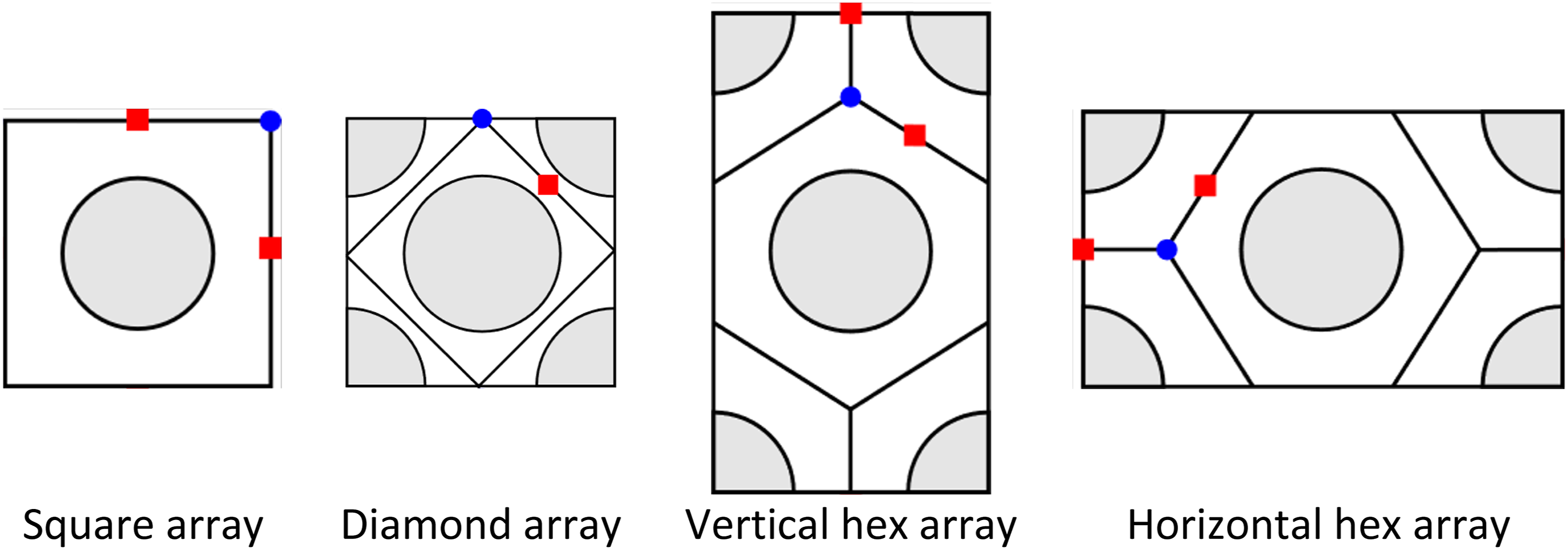
Contrary to that, a series of articles (in particular ref. 8) suggests using a square and a hex RVE, but transforming those RVEs by angles between 0° and 180°.
This article does not investigate whether regular fiber arrays are indeed accurate or conservative representations of a random fiber arrangement. It is only concerned with the necessary regular fiber arrays assuming that it is valid to use them in the first place. In regular fiber arrays, the fiber is assumed to be circular.
Limiting the investigation to regular RVEs, it can be shown that of the four proposed arrays (square, diamond, and vertical/horizontal hex) only a square and either one of the two hex fiber arrays have to be analyzed using FEA. The results for the other two can be derived analytically. It is straightforward to verify that transforming the FEA results for a square array yields identical values to running FEA for a diamond array. This is discussed in detail in ref. 9. The underlying principle can be formalized as
For the thermal amplification factors, a similar equation can be derived. Since they are a vector, only a single transformation
Ref. 6 also concluded that the results of the square and hex RVEs can and should be transformed. They do not include the Location of critical interrogation points for distortional matrix failure envelope.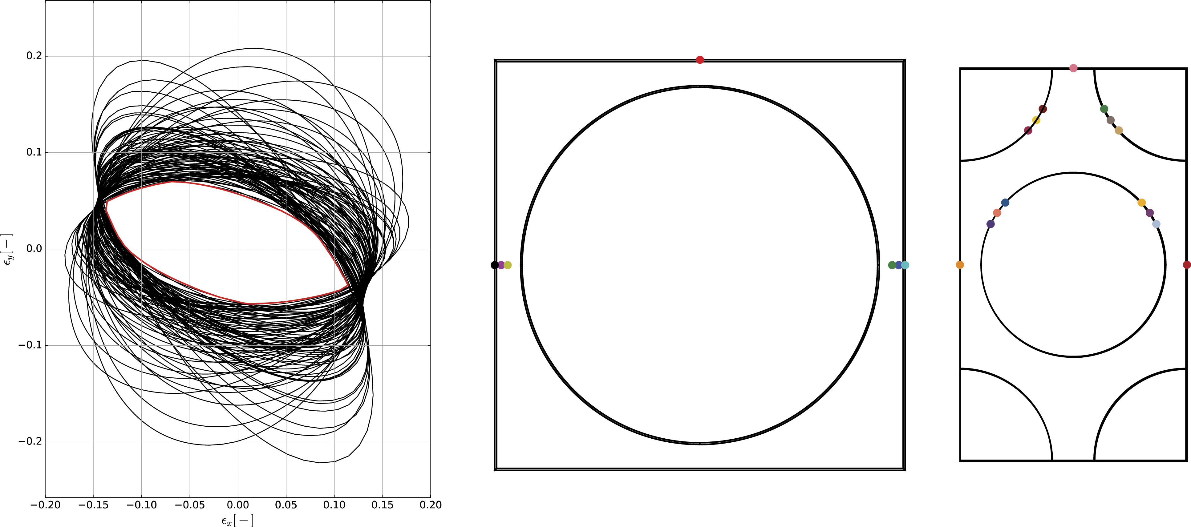
The process to obtain
Results of a square cell transformed using
In terms of the required angles, for the square cell angles of 0°, 90°, 180°, … give identical results due to rotational symmetry. Since points in one half of the RVEs are used (see Interrogation Points ), the same results are already obtained after 45°.
It should be emphasized that “the same results” is not intended to mean that any single point in the RVE returns the same results. The purpose of this application of Onset Theory is to draw failure envelopes. The proposed limited angle range causes the results of the two quadrants to be “switched”. Since all points are used to determine the failure envelopes, the relative location is irrelevant.
Based on these symmetry considerations, the only required angles are therefore 0° to 45°. For the hex cell, the same reasoning shows that 0° to 30° are sufficient. Including interrogation points in one half of the RVE and using symmetry reduces the range from the one proposed by ref. 6 (0° to 180°).
In summary, for conservatism strain amplification factors based on angles between 0° and 45° for a square base cell, and between 0° and 30° for a hex base cell, are needed. The degree increments depend on the desired fidelity of the results.
Boundary conditions (BCs) on representative volume elements (RVEs)
To determine the strain amplification factors, three types of loads are applied: thermal, shear, and normal loads. For the normal load cases there is contradicting information. Given an applied load, say along the fiber, the remaining faces (on which primary load is not applied) can be forced to remain in place (“fixed BCs”), as chosen by one of the original authors of SIFT, Jon Gosse (see e.g. ref. 4). The other original author, John Hart-Smith, allows the remaining faces to freely, uniformly translate normal to their original position (“movable BCs”), see ref. 5. For thermal and shear load cases, all main sources (i.e. the ones mentioned in the Introduction ) agree on using movable BCs for thermal loads and allowing the faces of the RVE to warp under shear loads.
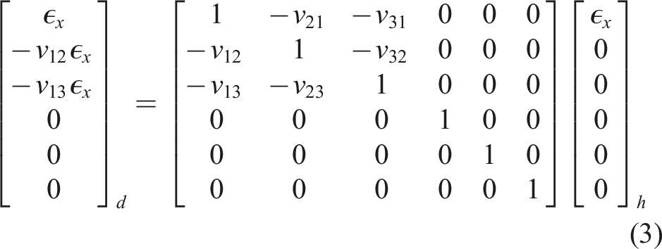
The correct BCs for the normal load cases can be determined by means of a thought experiment. Assume a RVE containing a single homogeneous isotropic material. In this case, dehomogenized and homogenized strains are the same. Clearly, this means amplification factors of 1 for mechanical loads. It turns out that this is equivalent to using fixed BCs. The enhancement factors are derived based on the application of a unit strain in one direction. If the faces are allowed to move, there will also be Poisson’s contractions, which are also strains. These strains (which would also be measured by for example strain gauges) have to be included in the homogenized state of strain. In equation form, this can be expressed as follows, where the dehomogenized (subscript “d”) strains are on the left, the matrix represents the amplification factors, and the homogenized (subscript “h”) strains are on the right:
However, given an appropriate choice of homogenized state of strain, movable BCs are also correct. In that case, the homogenized state of strain should not contain Poisson’s strains, because the Poisson’s effect is already contained in the matrix of amplification factors:
Either formulation is correct, and the strain amplification factors can be converted from one to the other, as discussed in ref. 9. To use the correct applied strain, it is important to be aware of the choice of BCs used during FEA.
In many experiments (e.g. laminate tests),
For thermal loads, a similar thought experiment confirms that movable BCS are correct. A temperature difference should not cause dehomogenized constituent strains which would cause failure. Since the material will expand or contract depending on the temperature, the strain-free state is achieved by allowing the boundaries to move. Ref. 6 arrived at the same conclusions and provides a complete summary of BCs. It should be strongly emphasized (as done in that article) that applied displacements in the long direction of the hex array need to be scaled by
Interrogation points
Since dehomogenized strains vary throughout the RVE, strain amplification factors have to be extracted at a number of “interrogation points”. For the matrix phase, ref. 3 and all other articles involving Jon Gosse (who is one of the original developers of Onset Theory) state that the most critical ones are the interstitial (IS; where fibers are furthest apart) and interfiber (IF, where they are closest) locations. These are indicated in the fiber arrays in Figure 1. Ref. 6 additionally includes points at the fiber/matrix interface on radial lines passing from the center of the fiber through the interfiber and interstitial points.
Regarding the fiber, ref. 10 uses points at its center, as well as on the fiber boundary at 0°, 45° and 90° (as measured from the horizontal), for both the square and the hex array. Others, e.g. ref. 11, use points at 0°, 30°, 60° and 90° on the fiber edge for the hex array.
Another aspect that should be considered is symmetry of the RVE. Ref. 3 only uses points in a single quadrant of the RVE, while ref. 11 uses points in one half of the RVE, and some authors such as ref. 12 investigate points around the entire fiber.
Ref. 9 investigated the necessary interrogation points based on the locations that were found to actually influence the failure envelope. Figure 2 shows an example of such an investigation. Distortional matrix failure envelopes based on a large number of interrogation points are drawn, and the points that contribute to the final failure envelope are indicated on schematics of the square and hex RVEs. A closer investigation of the contributions reveals that the points on the fiber/matrix interface have a minor contribution to the envelope and may only be critical due to the resolution of interrogation points or numerical inaccuracies when determining the intersection between failure envelopes. Example of dense grid of interrogation points (yellow circles) for a hex fiber array.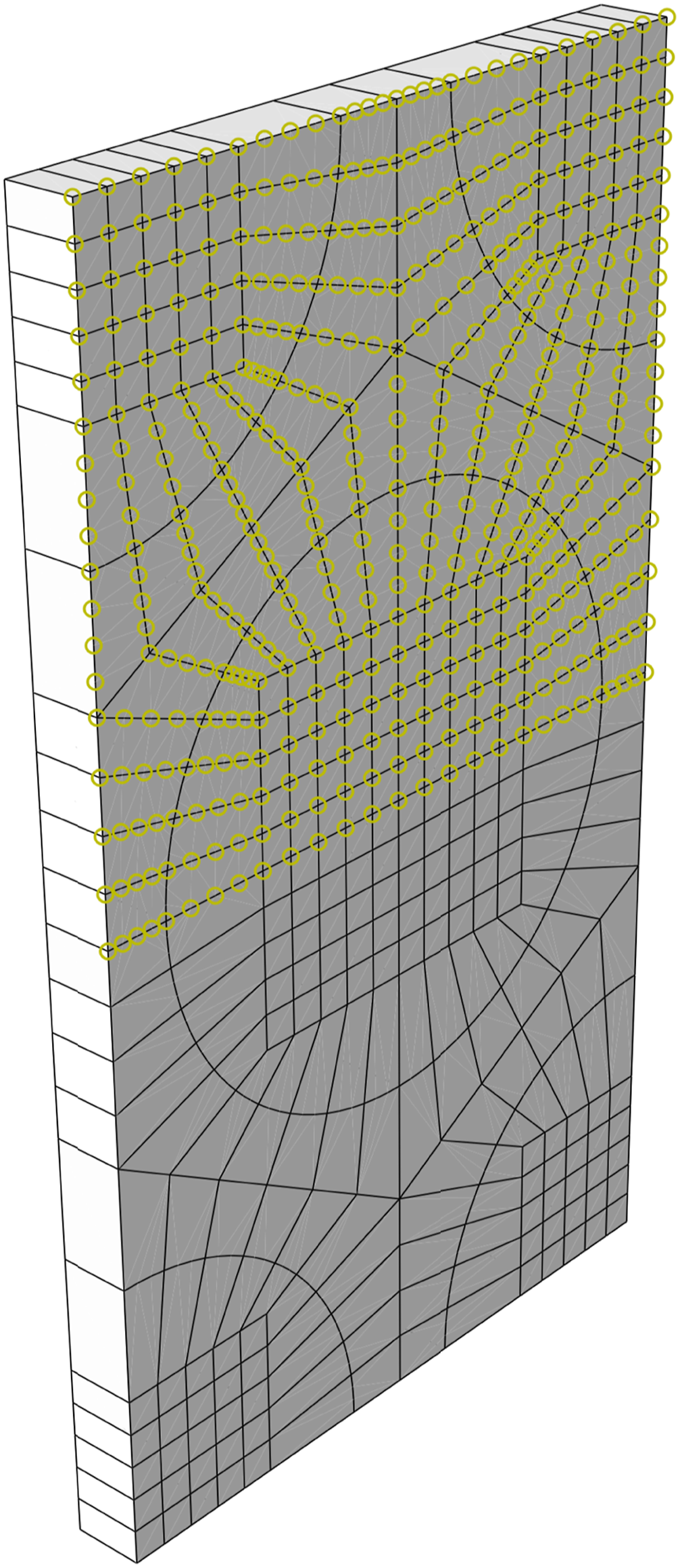
Distortional fiber and dilatational matrix failure were analyzed the same way. It is important to note that the investigation was limited to a relatively small number of failure envelopes. To ensure capturing the most conservative behavior, a dense grid of interrogation points should be used (see Figure 3). Within the scope of that investigation only the interfiber points of the square and hex arrays proved to be relevant for distortional matrix failure, if minor contributions to the failure envelope attributed to numerical inaccuracies were excluded. However, since this was only a single investigation this should not be taken to mean that other points can be discarded. Points at 0° and 90° on the fiber boundary determined dilatational matrix failure. Interestingly, the commonly used interstitial location was never critical for failure. For the fiber failure envelope, the fiber center and points at 0° and 90° on the fiber edge were critical. Necessity of using interrogation points in one half of the RVE.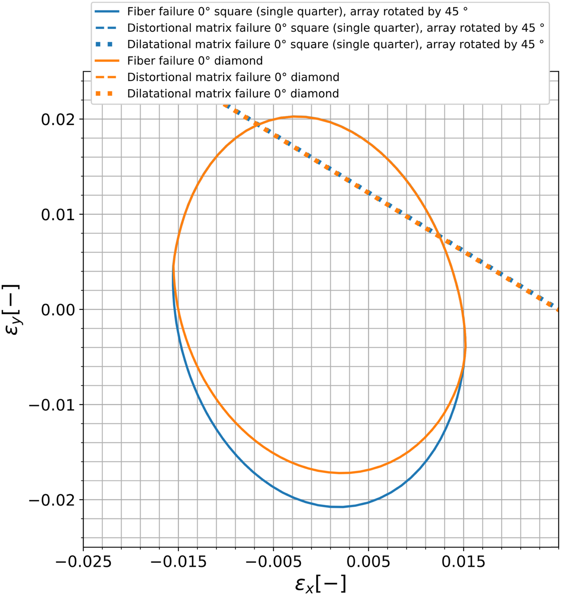
In terms of symmetry, it can be shown that using interrogation points in a single quadrant is insufficient. Instead, interrogation points in one half of the RVE need to be used, as indicated in Figure 3. The reason is that for an applied shear strain, neighboring quadrants of the RVE will have normal strain response components of equal magnitude but opposite sign. This means that in the expression for the distortional strain invariant (see
Strain Invariants
), for terms such as
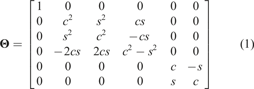
Another argument is related to the transformation of RVEs, as discussed in Fiber Array Types and Transformed Representative Volume Elements (RVEs) . If a square array is transformed with interrogation points in a single quadrant only, it fails to reproduce the failure envelope produced by a diamond RVE. This is shown in Figure 4.
Using interrogation points in only a single quadrant of the square RVE is clearly unconservative in the compression regime compared to the diamond RVE. If interrogation points in one half of the square RVE are used, the transformed square RVE correctly recovers the diamond cell failure envelope. Note that, as discussed in Fiber Array Types and Transformed Representative Volume Elements (RVEs) , this does not mean that any individual point in the RVE returns the same results.
In summary, this means that it is insufficient to use interrogation points in a single quadrant of the RVE if it is transformed, or if interrogation points are used that cause a coupling between shear and normal strains. Therefore, it is necessary to use interrogation points in one half of the RVE.
Homogenized state of strain
The homogenized state of strain contains three contributions. First of all, there are strains due to mechanical loads. These should only be mechanical strains (not total strains, defined as
In addition to that, there are two types of strains that depend on temperature, both on the macro level and on the micro level. On the macro level, thermally induced mechanical strains due to the difference between the application temperature and the curing temperature (assumed to be the strain free state) need to be taken into account. These occur due to a mismatch in thermal expansion coefficients of plies of different orientations. At the micro level, thermal strains arise due to the mismatch in thermal expansion coefficients of the constituents. These strains are determined using FEA and are included as the vector of thermal strain amplification factors,
As explained in
Boundary Conditions (BCs) on Representative Volume Elements (RVEs)
, if FEA was carried out for both the thermally induced mechanical strains and the applied strains, the results can be directly used as the homogenized state of strain. Else, the equations in
Poisson’s Effects
and
Thermally Induced Mechanical Strains
can be used as a proposed approach to determine the missing strain components, e.g. in the typical case of having
It should be emphasized that the expressions in this Section only capture applied in-plane strains. Similar equations could be derived for applied curvatures (i.e. bending).
Poisson’s effects
Poisson’s effects are an important aspect of the full state of strain. Neglecting it and using only the directly measured strains (e.g.
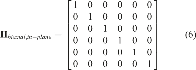
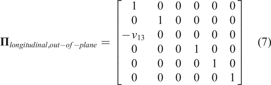
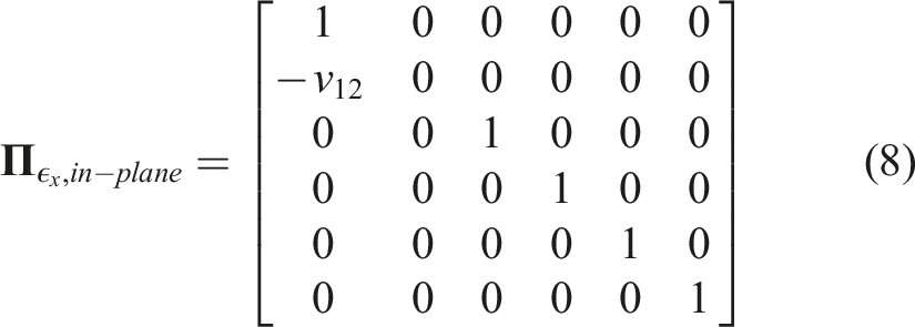
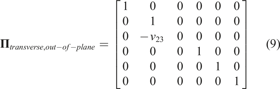
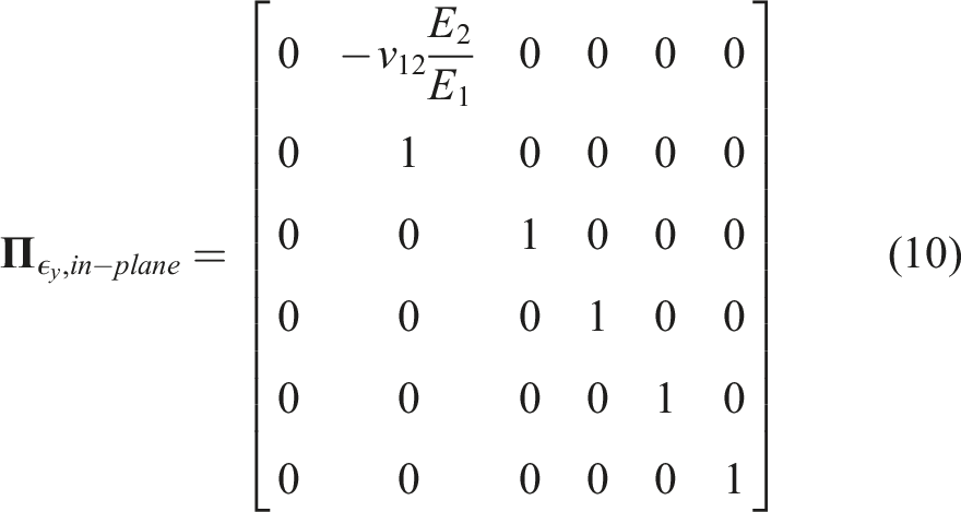
It is important to understand the use of ply and laminate properties. For the out-of-plane direction, the ply Poisson’s ratio (in the ply coordinate system) should be used. This is due to the fact that in that direction the stress is assumed to be zero (plane stress conditions), meaning that each ply experiences a strain according to its own Poisson’s ratios. On the other hand, for cases where in-plane Poisson’s effects need to be taken into account (for example for failure envelopes involving only one of
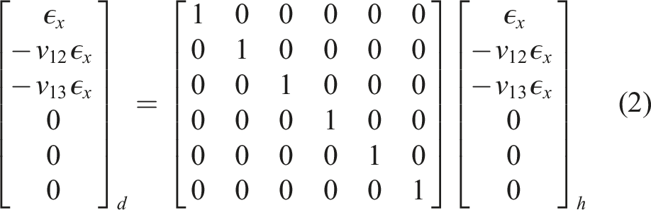
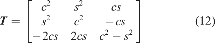
This means that in order to obtain the strain in a ply, a series of steps need to be followed. First of all, possible in-plane Poisson’s effects have to be applied to the known laminate strains. Subsequently, the strains have to be transformed into the ply coordinate system. Finally, out-of-plane Poisson’s effects need to be included. All of these steps are done in form of matrix multiplications. The resulting equation is
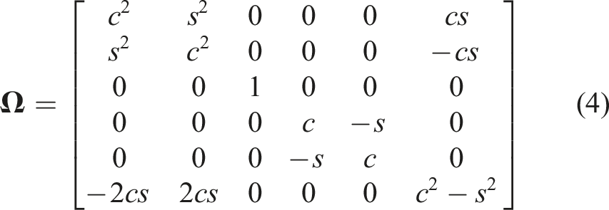
(
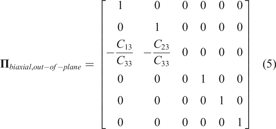
It should be stressed that the out-of-plane matrix depends on the resulting state of strain in the ply coordinate system. This means that a 90
Thermally induced mechanical strains
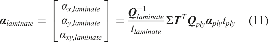
The thermally induced mechanical strains are based on the mismatch in thermal expansion coefficients between the ply and the laminate. The equations can once again easily be derived from classical lamination theory. By enforcing strain compatibility, the laminate thermal expansion coefficient can be calculated as
For typical (i.e. symmetric balanced) laminates, the shear component should evaluate to
Based on this, the in-plane thermally induced mechanical strains are calculated as the strains required to remove the discrepancy between the thermal expansion of the laminate and the free thermal expansion of a ply, in other words (in the ply coordinate system, and abbreviating thermally induced mechanical strains as
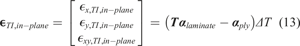
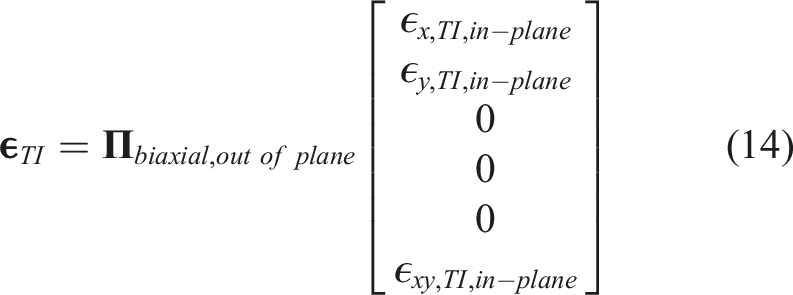
As discussed previously, these strains cause additional Poisson’s effects. Therefore, the final equation is
It should be emphasized that these strains are very important for matrix failure. They have the same effect as applied external strains. As an example, in Figure 7 dilatational matrix failure at Distribution of 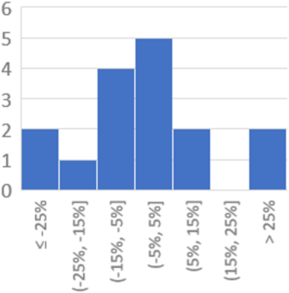
Strain invariants
Two strain invariants are used in Onset Theory. The first is the dilatational strain invariant, given by
For the distortional strain invariant, several versions are used in literature, all related to each other through a direct algebraic operation. The most common version is to use the equivalent strain (also known as von Mises strain due to its resemblance to the well-known von Mises yield criterion for isotropic materials), see equation (15).

Note that this equation is using engineering shear strains, e.g
Comparison of distortional invariant definitions.
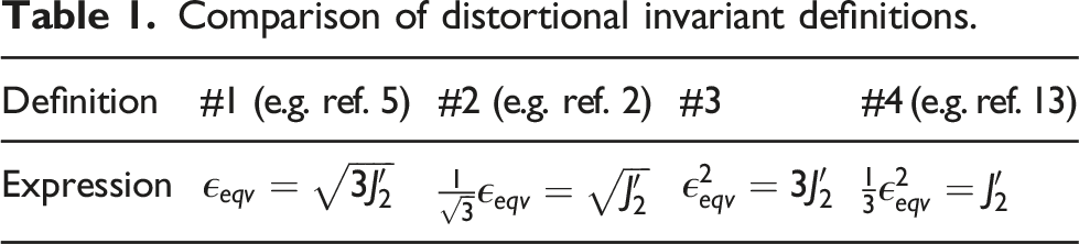
These different definitions can cause confusion or even incorrect results when looking at numerical values. In fact, if these varying definitions are taken into account, some trends in the critical invariants can be observed, as discussed next.
Observations regarding distortional invariants
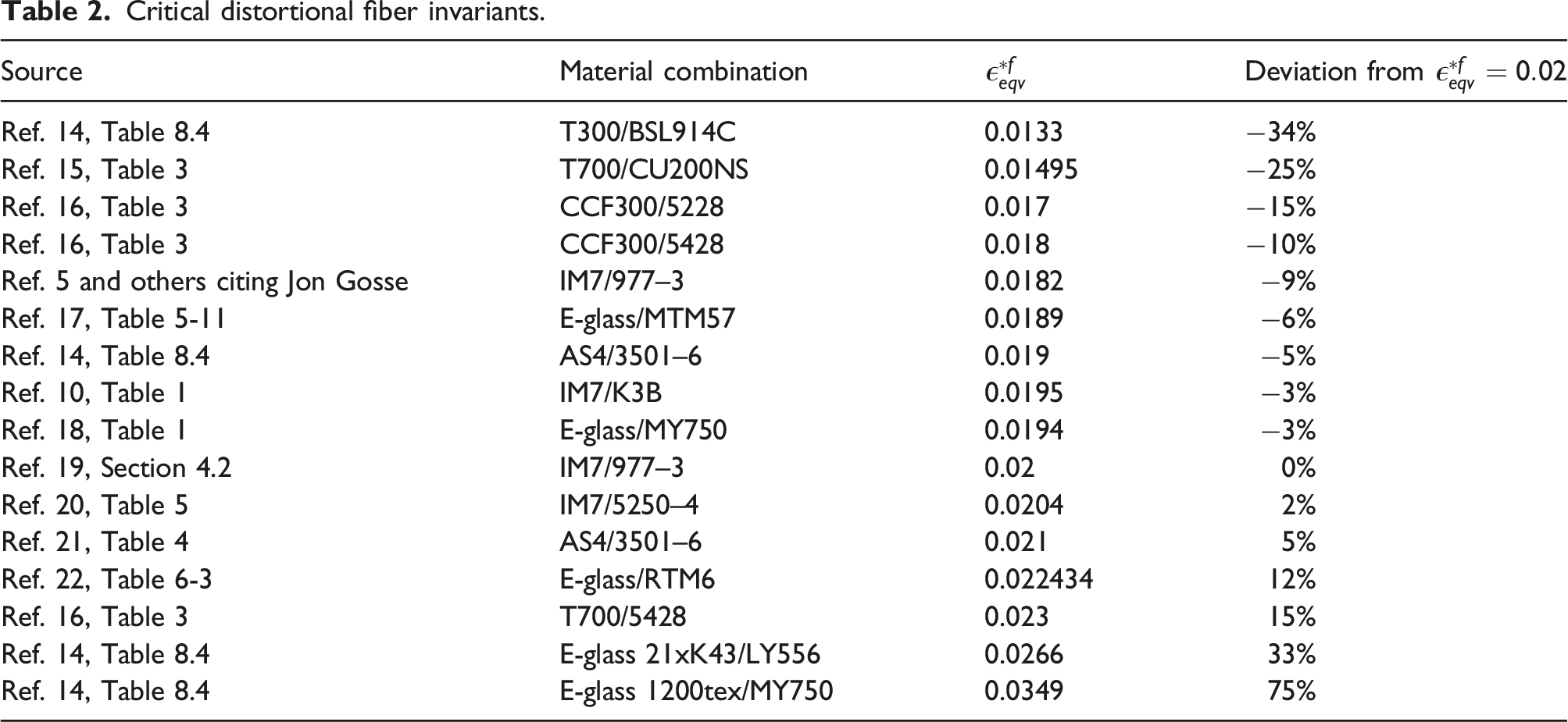
An extensive literature study of critical distortional invariants showed that the critical invariants for carbon fibers and E-glass are all similar, approximately Distribution of Critical distortional fiber invariants.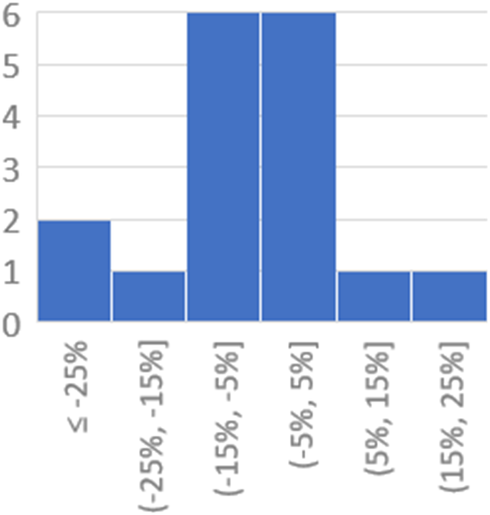
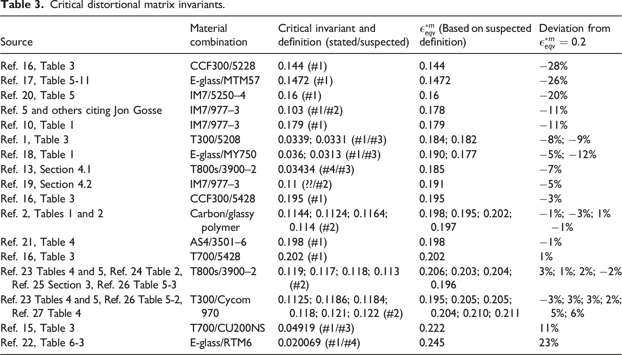
Critical distortional matrix invariants.
Comparison between prediction and biaxial strain test data for an AS4/3501–6 [90/±45/0]s laminate.
The cause is unclear, but to the knowledge of the authors this has not been published before. Composites using fibers from IM7 or AS4 to E-glass have vastly different strengths, so the similarity in critical strain invariants must be due to stiffness effects. Either the same homogenized failure strain results in different failure strengths, or due to MME identical dehomogenized constituent strains correspond to different homogenized strains. The former would be related to differences in the stiffness of the composite, while the latter would mean the individual constituent stiffnesses (together with e.g. fiber volume fraction) are the relevant factor. Ref. 9 contains a more thorough critical review of the sources.
Summary of consistent approach
This section is intended as a step-by-step procedure to apply Onset Theory.
Assumptions and limitations
Onset Theory in general, and the MME process in particular, is highly idealized. It assumes that RVEs are acceptable to obtain dehomogenized constituent from macro level strains. This implies that the lamina consists of a single, infinitely repeating type of RVE. Fibers are assumed to be perfectly circular. Fiber Array Types and Transformed Representative Volume Elements (RVEs) discussed these assumptions. Additionally, the analyses assume temperature-invariant material properties.
Onset Theory is a ply failure criterion (i.e. it is not used to predict interply failures such as delaminations). It works on thin, flat, orthotropic plies and laminates under plane stress. The equations in Homogenized State of Strain do not include bending loads, although analytical expressions for these cases can be derived as well.
Physically, Onset Theory asserts that there are two independent failure modes for any material: distortion and dilatation, and that carbon fibers only fail in distortion. Dilatational fiber failure would be another non-interactive cutoff on the failure envelope. However, there are no critical dilatational fiber invariants in literature.
Onset Theory does not include (micro)structural failures such as fiber kinking. Adding these types of failure modes as additional non-interactive cutoffs on the failure envelope should be a high priority research item.
It should be emphasized that Onset Theory should not be modified to use stress instead of strain invariants. Unlike stress invariants, strain invariants are independent of each other. There is an influence of the hydrostatic component of the stress (but not strain) on yield. This is not captured by the von Mises yield criterion. There are several other reasons, including a strain rate dependency of the critical stress (but not of the critical strain), as well as different failure stresses (but not strains) in compression versus tension. Ref. 26 explains these reasons in detail.
Micromechanical enhancement (MME)
It is important to use a consistent order of strain components during MME. In this article, the order will be
Amplification factors should be extracted from a dense grid of interrogation points in one half of the RVE (see
Interrogation Points
). As discussed in
Fiber Array Types and Transformed Representative Volume Elements (RVEs)
, square and hex fiber arrays are sufficient, transformed by 0
As
Boundary Conditions (BCs) on Representative Volume Elements (RVEs)
mentioned, ref. 6 came to the same conclusions about displacements and BCs for the RVE. These results will not be repeated here. The strain response at the interrogation points is used to determine
The mechanical amplification factors for
Evaluating failure
Using the expressions in
Strain Invariants
, failure occurs if either of the two invariants exceeds its critical value, i.e.
The available literature agrees that for typical carbon fibers, dilatational failure does not occur, while for resins both types of failure are observed. For example, according to ref. 5, “Carbon fibers used in the aerospace industry today fail by distortion, regardless of the nature of the load. They do not fail by dilatation”.
The strains in these equations are the components of the dehomogenized state of strain, given by
Example failure envelope
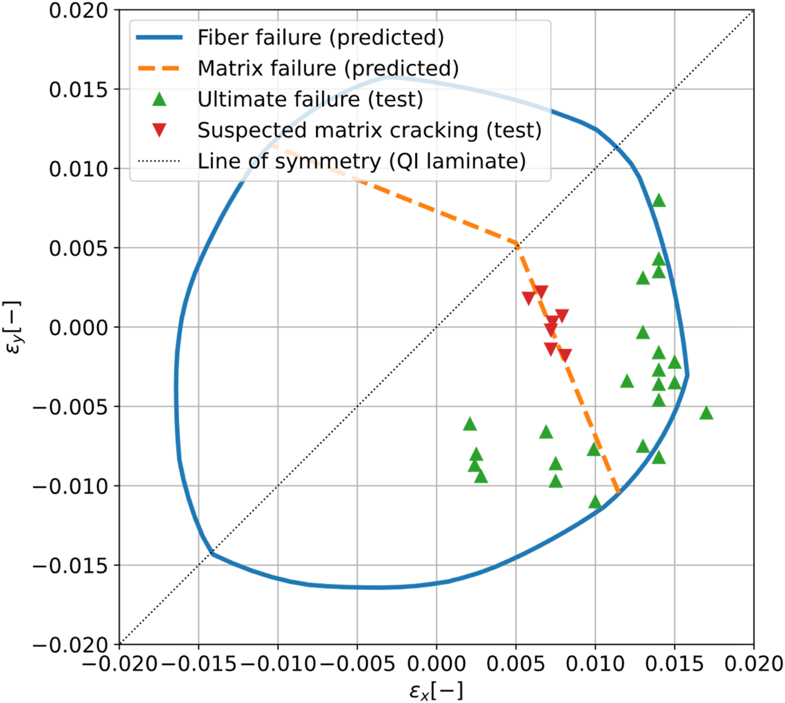
Using the consistent approach, failure envelopes were generated for several cases, including the AS4/3501-6 biaxial failure envelope from the WWFE (ref. 28). Constituent and lamina material properties can be found in Table 1-3 of that article. The curing temperature (assumed to be the strain free state) as well as the ultimate failure strains are available in Table 2 of refs. 29 and 30, while the location of suspected matrix cracking is reported in ref. 31. Finally, the “default” critical invariants from Strain Invariants are used.
Figure 7 shows the resulting failure envelope. Matrix cracking is predicted very closely, while the ultimate failure predictions were less accurate. In particular for compression-dominated states of strain, predictions were unconservative. A likely cause is that Onset Theory does not include microstructural failure modes such as fiber kinking. These failure modes should be added in form of other (non-interactive) cutoffs of the failure envelope in strain space.
The other point to note is the large scatter of the test data in the compression-dominated regime. On the same radial line, i.e. for the same strain ratio, values between
Finally, a perfect failure criterion, using the exact material properties from the test specimen, should predict the result achieved by a perfect test. In reality, some tests may even overachieve the perfect test results due to scatter in material properties. However, typically factors decreasing the test result such as manufacturing flaws will be more prevalent. This may be a partial explanation for the trend in the tension-dominated regime, where the failure predictions form an outer bound on the test data, with very few data points outside of the predicted envelope.
Conclusions
This paper summarizes recent findings which provide researchers with a consistent starting point for using Onset Theory.
One major open question which is outside the scope of this work is whether or not regular fiber arrays are a physically meaningful, accurate, or at the very least conservative, representation of the true random fiber array. Following the consensus in previously published literature on Onset Theory (see
Fiber Array Types and Transformed Representative Volume Elements (RVEs)
) the discussion in this paper is limited to regular fiber arrays. In that case, it was found that square and hex fiber arrays should be analyzed, and additional arrays should be included by transforming the results between 0
Analytical expressions for the full state of strain of a ply are developed, including Poisson’s strains and contributions from thermally induced mechanical strains. Alternatively, an FEA model could be used to determine these strains.
Critical distortional invariants (in this paper expressed as equivalent strain) are surprisingly consistent across materials and material classes: for most carbon and glass fibers
Applying the approach to test data obtained from the World Wide Failure Exercise shows excellent predictions of matrix cracking and good agreement for ultimate failure in tension/tension and tension/compression where tension is dominating. Tension/compression failure where compression is dominating is poorly predicted, which may be due to failure modes not included in Onset Theory (e.g. fiber kinking).
Footnotes
Acknowledgments
The authors wish to express their gratitude to ATG Europe B.V. and Delft University of Technology for their continuous support and assistance throughout this work.
Declaration of conflicting interests
The author(s) declared no potential conflicts of interest with respect to the research, authorship, and/or publication of this article.
Funding
The author disclosed receipt of the following financial support for the research, authorship, and/or publication of this article: This work was supported by the ATG Europe B.V., who provided the necessary equipment (computer hardware and software such as Abaqus) for the analyses carried out during this research. They also provided feedback on the research as well as the report.