
Abstract
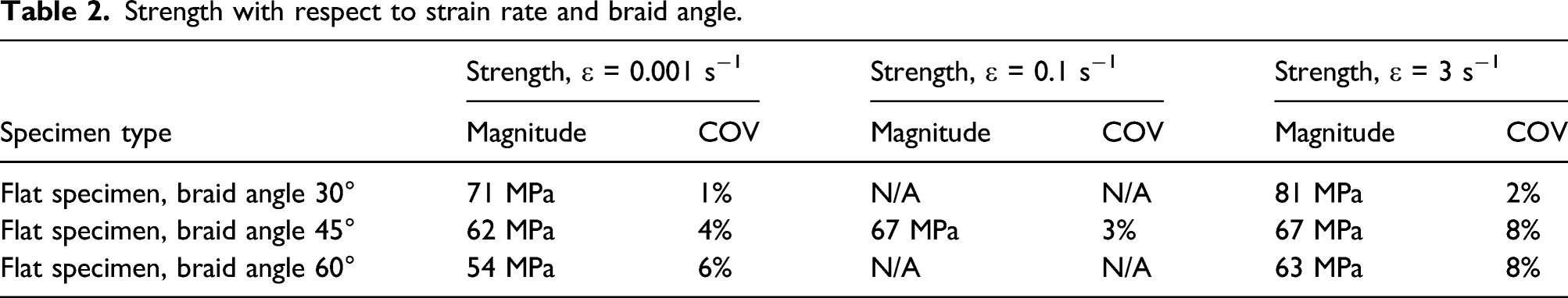
The in-plane shear strength of tri-axial braided composite materials was measured for three different braid angles (30°, 45°, and 60°) and two strain rates (0.001 s−1; 3 s−1) using the three-rail shear test. The in-plane shear strength was found to be sensitive to both—the braid angle and the strain rate. An increase of braid angle resulted in a reduction of shear strength, whilst an increase of loading rate resulted in an increase of shear strength of 8%–17%, depending on the braid angle.
Keywords
Introduction
Over the last decade, two-dimensional braided composite materials, produced in an RTM process, have gained an increasing interest in the automotive industry. The key driver for this evolution is—aside the typical composite benefits such as weight specific strength and weight specific stiffness—the high production rates and low cost compared to the established processes in the aeronautical industry making use of unidirectional prepreg material cured in an autoclave1,2 and the near net-shape manufacturing of closed form geometric profiles.3,4 Two different configurations are available for two-dimensional braided composite materials: bi-axial braids and tri-axial braids. The bi-axial configuration comprises two sets of yarns oriented in opposite directions, where yarns in one direction are interlacing with the yarns in the opposite direction, see Figure 1(a)). The tri-axial configuration features an additional set of yarns in longitudinal (warp) direction as shown in Figure 1 (b)). Whilst the bi-axial configuration is more commonly used, the tri-axial configuration offers increased axial modulus, tensile, and compressive strength.
5
Typical configurations of braided structures. (a) bi-axial braid; (b) tri-axial braid.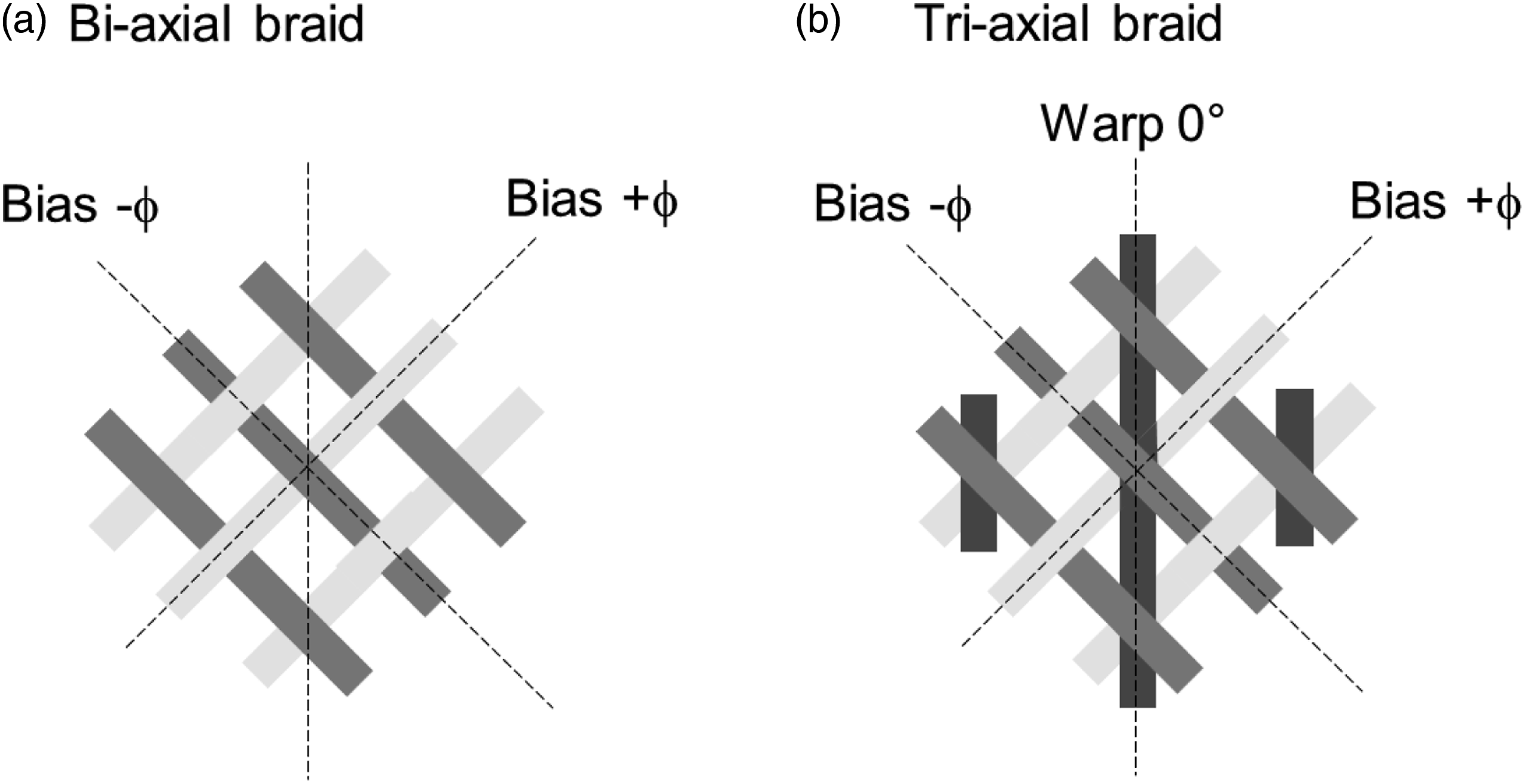
One key requirement for the application of composites as structural material in an automotive structure is the crashworthiness. Nowadays, in the development of a car it is essential that all materials used in safety-critical structures must be understood in sufficient detail to allow modeling their response in a crash scenario. Consequently, high quality material data must be generated using experiments, in particular capturing the highly anisotropic and non-linear response.6,7 One particular challenge arising when testing braided composite materials is the fact, that standard type coupons known from UD composite materials can often not be used for the characterization. One reason is that the scale of the inhomogeneity resulting from the braid structure (Dimension of unit cell: L x W in Figure 2) has a similar order of magnitude as the specimen dimensions and measurement range. This may affect test results and can result in considerable scatter. In order to be representative, a specimen should include at least 3–5 unit cells along the width and length, which posts a conflict with the standardized specimen dimensions known for UD composite materials. Unit cell (L × W) of a tri-axial braided composite.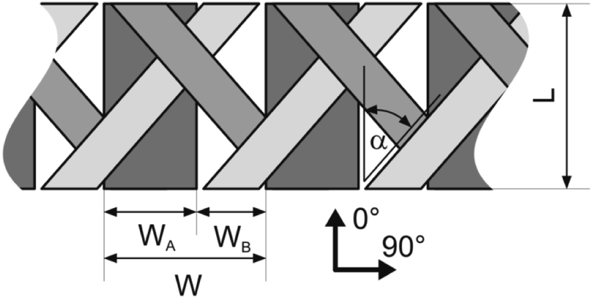
Another aspect to be considered in testing of tri-axial braided composites is the fact that some standardized stacking sequences used for characterization of UD material cannot (technically) be manufactured. For example, the in-plane shear test, utilizing +/45° specimen loaded in tension, specified in ISO 14,129 8 or ASTM D3518/D3518M, 9 cannot be performed for tri-axial braided composites as such a stacking sequence is excluded due to the additional fibers in warp direction. Therefore, alternative test methods have to be used for characterizing the in-plane shear behavior of tri-axial braided composites. A promising alternative test method is torsion testing of braided tubes. This test method is particularly attractive as the natural shape of a tri-axial braided preform is a long tube. This test method has, for example, been adopted by Harte and Fleck, 10 who studied the different failure modes occurring in braided tubes under torsional loading, Potluri and co-workers, 11 who studied the effect of braid angle on the torsional properties of braided composites, or Chai and co-workers,12,13 who studied the evolution of micro-damage using in-situ tomography. Researchers at NASA developed an H-shaped specimen,14,15 which is used in a test rig based on ASTM D7078 V-notched rail shear test method. 16 An alternative to this two-rail shear test method is the three-rail shear test, specified in ASTM D4255/D4255M. 17 It is further known that the properties of composite materials may be affected by the rate of loading, in particular if matrix-dominated properties prevail the response.18,19 For example, for unidirectional (UD) composite materials, rate effects have been reported for the mode I and mode II interlaminar fracture toughness,20,21 the transverse tensile 18,22 and compressive strength,23,24 or the in-plane shear strength.25,26,27 For textile composites, rate effects have been reported for off-axis compression of woven composites,28,29,30 the out-of-plane-shear strength of weft-knitted and woven composites. 31 Only very limited high-rate data has been reported for tri-axial braided composite materials. Salvi et al. 32 investigated the strain rate dependent response of tri-axial braided carbon composite materials (axial tows in 0° direction, biased tows in +/−45° direction) subjected to off-axis compression loading. In the experiments, the axial tows were oriented at 30°, 60°, and 75° with respect to the direction of loading, resulting in combined compression and shear loading of the fiber-matrix interface. Quasi-static tests were carried out on a universal test machine; high-rate tests were carried out using a drop tower setup. Salvi et al. reported a decrease of equivalent stress with increasing loading rate, which was attributed to diminishing local shear transfer resulting in reduced influence of the fibers during loading. However, no direct measurements of the rate-dependent shear strength of tri-axial braided composites have been reported so far. Given this limited amount of high-rate data on tri-axial braided composites, this paper is a first step toward closing this research gap and providing first insight into the rate-dependent response of tri-axial braided composites subjected to in-plane shear loading.
Experiments
Material description
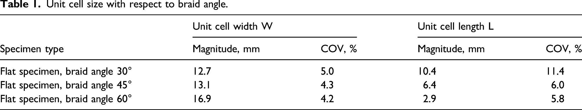
Unit cell size with respect to braid angle.
Specimen and test configuration
Given the large size of the unit cells, evaluating the rate-dependent shear strength requires relatively large specimens in order to ensure that the test volume is representative for the composite. The requirement of having at least three to five unit cells in each of the direction of the gauge section can be met by torsion testing of tubular specimens or the rail-shear methods. Rate-dependent torsion testing is possible using a torsional Hopkinson bar, as shown by Abbas Abdullah and Khalaf. 33 However, as such a device was not available at the time of testing, it was decided to characterize the rate-dependent shear response using a three-rail shear method on a servo-hydraulic test machine. The specimens were extracted from the plates using a high-speed milling process. The specimen dimensions were 200 mm × 100 mm; the thickness of the specimens was 3.2 mm for specimens with bias 45°, 3.2 mm for specimens with bias 60° and 3.0 mm for specimens with bias 30°. A total of nine holes were drilled into the specimens in order to allow fixing the into the three-rail shear test rig, which was mounted into a servo-hydraulic test machine. The achievable strain rate was limited by the large size of the specimens and the weight of the test fixture (approx. 40 kg), which might result in undesirable oscillations during testing.
Three strain rates were evaluated, which were not compromised by inertia effects. The lowest (quasi-static) strain rate was 0.001 s−1, the intermediate strain rate (only for 45° bias) was 0.1 s−1, and the highest strain rate was 3 s−1. A minimum of three specimens were tested for each combination of braid bias (30° bias, 60° bias) and loading rate (0.001 s−1, 3 s−1). For specimens with braid bias of 45°, a total of five specimens were tested for each of the three loading rates. The local strain on the specimen was evaluated using digital image correlation, the forces were recorded with the machine-internal load cell. However, it should be noted that the strains recorded at the surface may not necessarily be representative for the strains inside the specimen. 34 For this reason, only strength data is reported here.
Results and discussion
Figure 4 summarizes the shear strengths measured for the different braid angles and strain rates. The lowest rate data is shown in blue diamonds; the intermediate rate date is shown with a green cross, the highest rate data is shown in red circles. The error bars indicate the coefficient of variation (COV), defined by the standard deviation divided by the mean value. High-resolution photography of a tri-axial braided composite: (a) top view, (b) cross-section.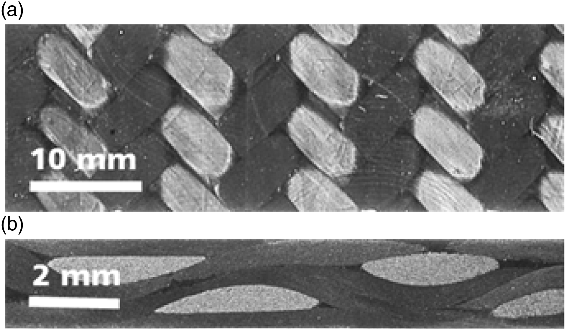
Two very distinct trends can be observed: On the one hand, the braid angle has significant influence on the shear strength. For the material investigated here, an increase of the bias braid angle results in a reduction of shear strength. The second trend that can be observed is that the increase of loading rate results in an increase of shear strength for all specimen configurations. These results are discussed in the following:
Influence of braid angle
Figure 4 indicates a direct correlation between the measured shear strength and the braid angle. For both, the quasi-static experiments and the high-rate experiments, a linear decrease of strength is observed for an increase of braid angle. This finding is in contrast to analytical predictions by Jing et al. 35 who predicted the maximum shear strength for tri-axial braided composites to occur for a braid angle of 45°. However, the Jing-model assumes that the fiber volume fraction of the different laminates is independent of the braid angle. However, in practice, the braid angle has been shown to have a direct influence on the fiber volume fraction, 36 which is also thought to be the case for the composites tested here (note: the difference in specimen thickness for different braid angles described in Specimen and test configuration). Furthermore, the braid angle direct influences the local crimp of the fabric and therefore the stiffness and strength of fabrics. 37 Endurweit and Long 38 showed that for tri-axial braided fabrics, infiltrated in warp-direction, the permeability of the fabric decreased with increasing bias angle. We believe that this might also contribute to the observations as lower permeability would result in higher void-content and therefore potentially in a decrease of mechanical properties, in particular for resin-dominated properties such as the shear strength.
Influence of loading rate
Strength with respect to strain rate and braid angle.
The rate-dependent mechanical response of braided composites is influenced by the rate-dependent response of the constituents (fiber and resin). For carbon fiber reinforced composites, the fiber-dominated properties, such as the 0° tensile strength typically do not vary with loading, see, for example.39,40 However, the polymers used for the matrix are known to be sensitive to the loading rate.
41
Therefore, for rate-sensitive resins, it is to be expected that the properties of braided composites, which are dominated by the resin or the fiber-resin interface are sensitive to loading rates. The in-plane shear properties of composites are strongly dependent on the resin, which in turn explains the increase of shear strength with increasing loading rate. Shear strength as a function of braid angle and loading rate.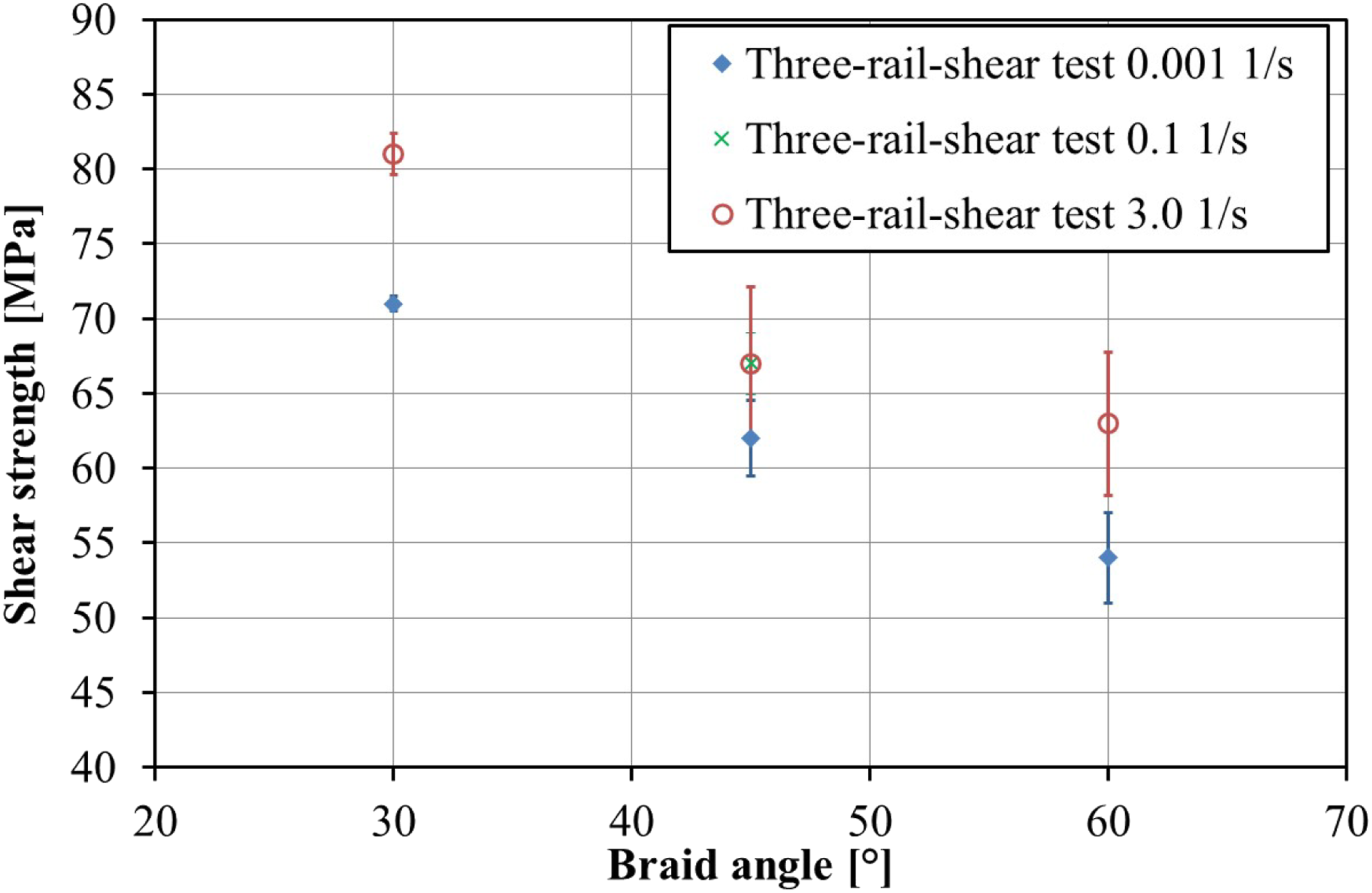
Limitations of the test setup
Within this experimental test campaign, the three-rail shear test was employed to characterize the in-plane shear response of tri-axial braided composites for loading rates ranging from 0.001 s−1 to 3 s−1. This test setup is chosen as it allows for testing of large-size tri-axial braided composites of dimensions extending over several unit cells, thus being representative for real structures. The specimens failed in a reproducible manner with only little scatter.
However, for the experimental work carried out here, the strain rates were limited to 3 s−1. There are two reasons for this limitation: Firstly, it is commonly known that miniaturization of specimens is the key for increasing the loading rate. However, the requirements imposed by the large size of the unit cells prohibit specimen miniaturization. Secondly, the test rig used for the three-rail shear testing weighs approximately 40 kg. Using this in a servo-hydraulic machine at higher loading rates would inevitably lead to oscillations in the load signal, which might disguise the real measurement data. An alternative approach that could potentially be used to increase the loading rate is to mount the specimen into a drop tower setup. However, our experience with other braided materials has shown that this setup is also compromised by a low-frequency oscillation, strongly influencing the load signal. A way forward in order to achieve higher strain rates could be the design of a topology optimized, light-weight three-rail shear test rig, maybe made from high-strength aluminum, which could then be mounted within a high-speed tensile test machine or a drop tower.
Conclusion
In the past, rate-dependent characterization of tri-axial braided composites was limited to tensile and compressive properties. In this manuscript, for the first time, the rate-dependent shear response of tri-axial braided composites was studied over three orders of magnitude (0.001 s−1 to 3 s−1) using the three-rail shear test. The three-rail shear test was chosen as it allows the controlled introduction of shear loads into tri-axial braided structures at quasi-static and elevated loading rates, which is a challenge for most standardized test configurations. However, due to the required large specimen size, not allowing maximization of strain rate by miniaturization of specimen size, and in particular due to the large mass of the three-rail shear test rig (∼40 kg), potentially inducing undesirable inertia effects on the load signal, the upper strain rate, which can be achieved, is limited. Three different braid angles (30°, 45°, and 60°) were studied at quasi-static and dynamic conditions. Two trends could be observed: 1.) The in-plane shear strength decreases with increasing braid angle. 2.) The in-plane shear strength increases with increasing loading rate.
The first observation is a result of several mechanisms, such as the variation of fiber volume fraction, the local variation of crimp, and the local void content. The second observation can be explained by the contribution of a rate-sensitive epoxy resin.
Further work should focus on the development of a lightweight three-rail shear test setup, which could be used in a drop tower or a high-speed servo-hydraulic machine in order to increase the range of strain rates, which can be tested.
Footnotes
Declaration of conflicting interests
The author(s) declared no potential conflicts of interest with respect to the research, authorship, and/or publication of this article.
Funding
The author(s) disclosed receipt of the following financial support for the research, authorship, and/or publication of this article: This study is supported by BMW.