
Abstract
The onset of damage caused by the free-edge effect in plain-woven carbon fiber reinforced plastic (CFRP) specimens with an out-of-plane waviness under tension-tension fatigue loading is investigated. Numerical calculations show that interlaminar and intralaminar stresses close to the out-of-plane waviness are higher than the equivalent stresses at the surrounding edge regions. Using submodels, the influence of the chosen out-of-plane waviness can be better assessed. The free-edge effect of the considered specimens, which originates from stress gradients between plies of different orientation, is altered by the change in the stress field caused by the out-of-plane waviness. Large interlaminar stresses between plies of the same orientation are obtained, which contrasts with existing literature. In experimental fatigue testing it is found that cracks at the free edge appeared at the predicted locations, and after reaching crack saturation, in regions close to the out-of-plane waviness, interlaminar and intralaminar stresses lead to additional cracks along the whole free edges. The experimental tests are supported by a three dimensional image correlation system (3D-DIC), a thermal-imager and a digital photographic camera, which allows detailed examination of selected areas. Visual observation during fatigue testing and post-mortem inspection show good agreement between experimental data and numerical calculations in relation to the location of the damage initiation. As a result, out-of-plane waviness at free edges must be considered as an additional significant fatigue damage initiation location in laminate analysis.
Introduction
Plain-woven carbon fiber reinforced plastics (CFRP) are widely used due to their good handling usability and tolerance against impact damages. Nowadays, use of these materials are very common in the aerospace industry, mostly for thin-walled structural components.1,2 Consequently, analytical and numerical approaches have been developed in the last 50 years to analyze and design such structural components. As already emphasized by Mittelstedt, 3 the calculations were initially based on the classical laminate plate theory (CLPT), but in this theory, stress components in thickness direction are not taken into account. In order to design damage-tolerant components, it is necessary to consider all potentially detrimental influences on the fatigue strength. Therefore, it is essential to take the finite dimensions and possible defects into account. They may emerge during the manufacturing process, or in operational service and can result in premature failure. Such manufacturing defects are e.g. dry spots, in-plane fiber waviness, ply folds4–6 and out-of-plane waviness. Out-of-plane waviness, which are also termed wrinkles have already been studied in detail, whereby the attention was placed on the different geometries as well as on different materials and locations. However, it was found that wrinkles are often supported by resin pockets. For their experimental investigations wrinkles were artificially created by laminating over a steel rod, or by adding extra lamina strips.7–9 In order to determine the effect of wrinkles experimentally, digital image correlation was used. Elhajjar et al. demonstrated that for static tensile loading, interlaminar cracks along the sides could be detected, while observing the front surface. 10 However, only static measurements on unidirectional laminates were made.
An often overlooked phenomenon which causes reduction in fatigue strength even in defect-free material is the free-edge effect. At free edges, a three-dimensional stress state is present, which is caused by adjacent plies of different orientation or different material properties. More precisely, the associated interlaminar stress components are involved in causing the free-edge effect.11,12
According to Saeger, 13 who investigated interlaminar stresses in plates with holes, the two phenomena that lead to these stresses should be considered separately from each other. These are on the one hand stress gradients in the load field, caused by the presence of a hole, and on the other hand the free-edge effect. However, woven fabrics are not discussed in this context.
The free-edge effect on plain-woven CFRP was described by Whitcomb et al. 14 They carried out linear-elastic numerical investigations on unit cells and thus obtained conclusions regarding the free-edge effect on the stresses within the plain-woven laminate. In their findings, they underlined the influence of the weave architecture on the interlaminar stresses. This was confirmed by Espadas-Escalante, 15 where again the problem was analyzed on a numerical basis while considering woven plies. In addition, intralaminar stresses at the free edge were discussed.
The present article expands the analysis of plain-woven CFRP to include an imperfection and considers damage initiation at the free edge under tensile fatigue. In detail, the influence of a geometrical half-wave imperfection, which is applied to thin plain-woven CFRP with symmetrical layup, on interlaminar and intralaminar stresses under cyclic tension-tension loading is examined. The focus of the investigation is placed on the accelerated onset of damage by the free-edge effect. Besides the complex stress state, this out-of-plane waviness leads to a distortion of the load field. Furthermore, this work includes the comparison of experimental and numerical results. Therefore, a global model is created for the numerical calculation, with which areas with high interlaminar stresses are identified. In the following, submodels are defined, to which boundary conditions of the global model are imposed. These submodels provide a more detailed description of the free-edge effect. The results gained from experimental tests are used to validate the global numerical model and to evaluate the onset of damage due to the free-edge effect in the submodels.
The article is structured as follows. First the geometry of the specimen and the material are specified. In the next section the test set-up is described. This includes the specimen preparation, a description of the measuring equipment and the explanation of the test program. Numerical modelling and result presentation are followed by the experimental result section. Prior to the conclusions, a discussion of the results will be given.
Geometry and used material
Flat specimens with a half-wave imperfection are used to investigate the influence of an out-of-plane waviness on the damage initiation caused by the free-edge effect. In order to ensure a high repeatability in the production of specimens, an artificial form of the half-wave imperfection is assumed. A rather small waviness is introduced as this may be less likely picked up by quality control, yielding a more practically relevant imperfection case. The specimen geometry and the associated dimensions are shown in Figure 1. Also, the clamping tabs are depicted, which are glued on for the experimental tests. In addition, a detailed front side view with the unsupported waviness is presented. In general, resin pockets would emerge at the waviness, which would support the waviness zone. In this investigation, the resin pockets are not taken into account as a negligible influence on the free-edge effect during tensile cyclic loading is assumed. Moreover, resin pockets would prohibit the DIC measurements.
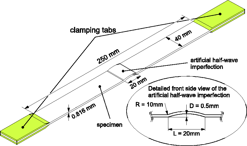
Geometry and associated dimensions of the specimen with half-wave imperfection.
Four plain-woven CFRP prepreg plies with a ply thickness of 0.204 mm are used to assembly the layup. The prepreg is composed of 3k-T650 tows and impregnated with a modified Solvay CYCOM® 970 epoxy resin. The fiber volume fraction is 0.6 inside the tow and the tow volume fraction is 0.756 in the weave. For this study a stacking sequence of
Material properties of the prepreg components.
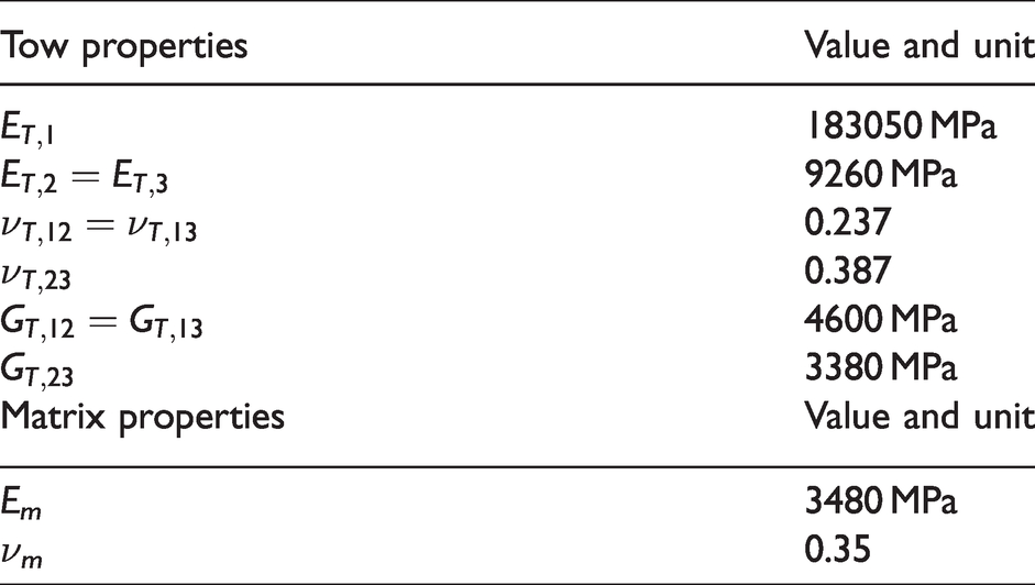
It is assumed that the tows have transverse isotropic material behavior and the matrix is isotropic. The parameters which are assigned to the tow are designated with T, those of the matrix with m. To differentiate between the waviness of the woven material and the waviness caused by the half-wave imperfection, the waviness ratio WR = h/λ is compared with the aspect ratio AR = D/L. Where h is the thickness of the ply, λ the wavelength of the tow, 14 D is the depth of the imperfection and L the length of it. This gives a waviness ratio WR = 0.05 and an aspect ratio of AR = 0.025.
Test set-up
To produce the desired geometry of the specimens with half-wave imperfection, first the contour of the half-wave imperfection was milled into an aluminum plate. In a subsequent step, a CFRP mould was obtained out from this aluminum plate. On this moulded form, the four plies with a stacking sequence of
A n
All experimental tests are carried out with a BPS-LH0025 servo-hydraulic cylinder from Zwick-Roell® that allows to apply loads up to 25 kN. Hydraulic wedge grips MTS 647 are used to clamp the specimens in the testing facility. In order to ensure that only tensile loads are applied, the grips are secured against rotation using self-developed guide columns and slide bearings. 5 In Figure 2, a schematic representation of the test set-up and location of the optical measuring devices is given. To compare the strains computed with the submodels with those from experimental testing, the DIC would need to be focused on the free edge. The thin laminate thickness of 0.816 mm restricts the DIC use, since the available standard-lens equipped system cannot evaluate and track such thin surfaces. Consequently, the 3D-DIC system is arranged in such a way that the cameras focus on the indentation due to the half-wave imperfection. The thermo-imager is positioned opposite to the 3D-DIC system. In addition, a digital photographic camera is mounted in front of the specimens positioned opposite to the 3Consequently, the 3d, the grips are secured against rotation using self-developedonset of possible cracks.
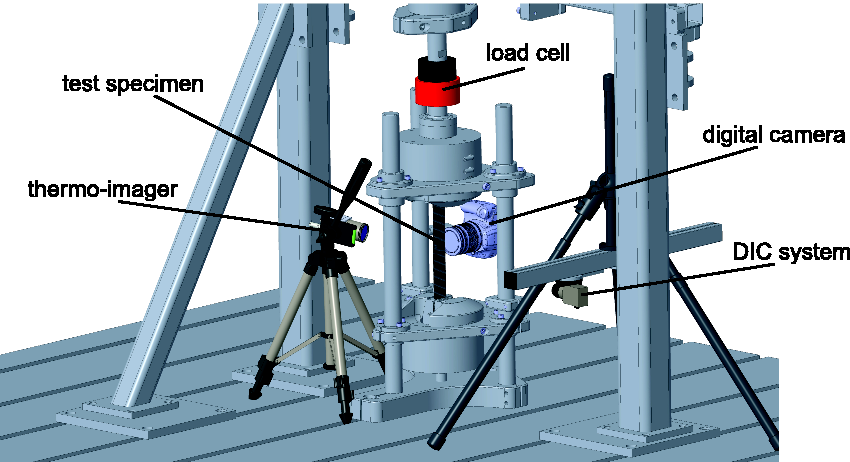
Test set-up with operated optical measuring devices.
From static tests, which are based on ASTM D4762-18, the stress levels for cyclic testing are identified. For the static test series, six specimens are used. Cyclic tests are then carried out at a stress ratio of R = 0.1 and at two different upper stress levels, which equal 75 and 80 percent of the average static tensile strength. All tests are performed until total fracture of the specimen has occurred or two million cycles are reached.
The controlling of the specified test program is performed with a CATS Control Cube system, whereas a sequence block is repeated multiple times throughout the specified test program. A schematic representation of a single sequence is shown in Figure 3. Thereby a rest phase for t = 10 s at
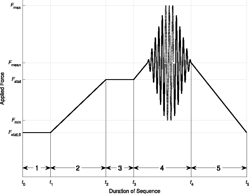
Schematic representation of a sequence block, which is the main constituent of the test program.
Numerical models
The influence of the half-wave imperfection regarding the free-edge effect is assessed by numerical calculations. For this purpose, numerical finite element (FE) models of a straight reference specimen and a specimen with a half-wave imperfection are created with Abaqus 2018. These global FE models are used to provide the boundary conditions for the submodels. The generated global model of the straight reference specimen differs from the specimen with a half-wave imperfection only by the missing imperfection and a coarser mesh. Boundary conditions remain the same. The straight reference specimen is used to emphasize the influence of the half-wave imperfection. Therefore three different submodels are generated. As locations for submodels the following regions are selected. The position of the submodel variants defined for the straight reference specimen are in the centre of the associated FE model, whereby one side of the submodels coincides with the free edge of the straight reference specimen. Two submodels are created for the specimen with a half-wave imperfection. The position of these submodels are depicted in Figure 4. A submodel is placed in the transition region and another submodel in the middle of the waviness. All submodels are placed at the free edge of the associated global model. Again one side of the submodels coincides with the free edge. For each submodel two variants are taken into account (cf. Figure 5). The difference between the two arrangements, which from now on are named standard variant and shifted variant, is that for the shifted variant, ply 2 and ply 3 are shifted by half of the weave pattern along the Y-axis (cf. Figure 5). The shift affects the position of ply 2 and ply 3 so that the
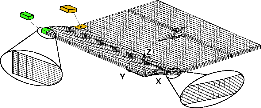
FE model of the specimen with half-wave imperfection with enlarged elements and schematic of the submodels (only one quarter of model displayed for better representation;
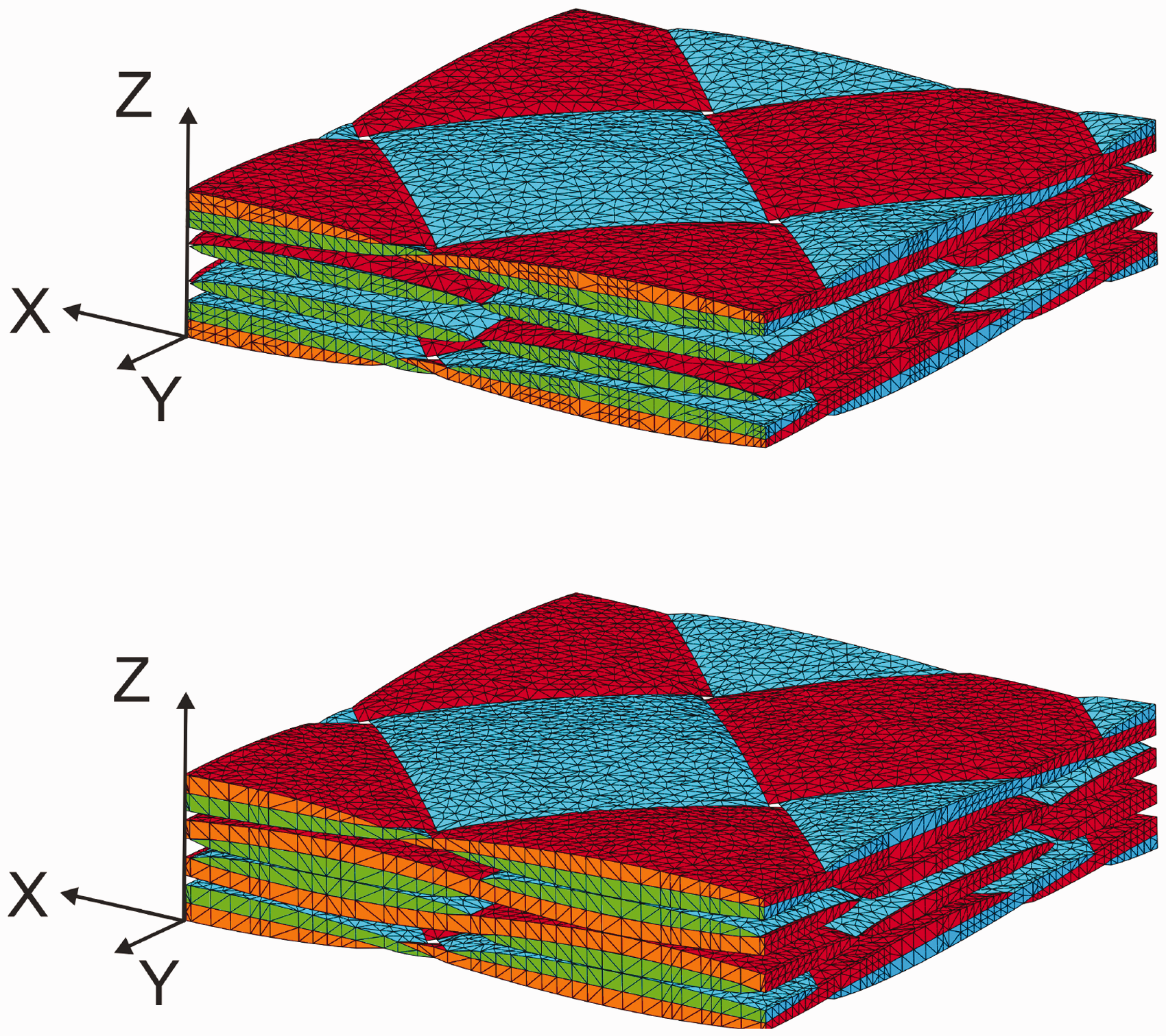
Meshes of the submodels of the standard variant (top) and the shifted variant (bottom).
The two variants of the submodel, which are defined for the reference specimen, the center of the half-wave imperfection and for the transition radius, are used to describe the free-edge effect. For the created submodels, the stress components
The material properties for the plies of the global FE models are calculated from the component properties. They are assigned to the FE models as engineering constants. The coordinate systems are positioned at the half of the width, whereby the origin of the specimen with a half-wave imperfection is located within the half-wave. The coordinate system used to define the
In Figure 4, a representation of the generated mesh for the specimen with half-wave imperfection, the coordinate system of a
According to the experimental test set-up, the boundary conditions for the global FE models are assigned. The global FE models are fixed at one end (X-, Y- and Z-directions of every node of the model face) and the nodes located at the other end are translated by displacement boundary conditions along the X-axis. Due to the long specimens length, the Poissone Poisson other end are translated by displacement boundary conditions along the X-axis. Due to the when a tensile force of
Using TexGen, 17 the submodels are created and exported for analysis in Abaqus. The dimensions of the tows and the thickness of the plies, as well as the spacing between tows, are considered. The corresponding material properties of tows and matrix are listed in Table 1. It is assumed that tows and matrix are ideally bonded. As already mentioned, the resulting displacements of the global FE models are transferred to the submodels as boundary conditions. Thereby, the displacements of the individual nodes of the global FE models are interpolated onto the nodes of the submodels. In more detail, the nodes of the matrix and the nodes of the tows, which are located at the lateral surfaces, are used. Only the nodes placed at the free edge and at the upper and lower surface are not included. In Figure 5 the two variants of the created submodels are depicted, whereby the matrix has been hidden for an improved visualization. In addition, the elements that are located on the free edge are displayed in a different color. However, as can be seen in Figure 4, the submodels in the transition radius and in the middle of the waviness are not planar in shape. But since TexGen can only handle planar models, an intermediate load step is required in which the submodels are forced into the required shape. In this intermediate load step the initially straight submodels are formed into the specimen specimenn this intermediate loadsubmodels are stress-relieved from residual forming stresses and used for the analysis.
In order to evaluate the strain components relevant for the free-edge effect, paths are defined for the individual submodels and associated variants. These paths are shown in Figures 6 to 8. The two variants of the reference submodels are shown in Figure 6. The paths are arranged equidistant over the length. Those paths for the submodel of the standard reference model are denoted with Ro, those for the shifted reference model with Rs. Similar to the paths arranged for the reference submodels the paths for the center submodels are defined in Figure 7. The paths of the standard submodel are labeled Co, the shifted variant is identified by Cs. Finally the paths for the submodels of the transition radius are defined in Figure 8. Again the paths of the standard variant are denoted with To, the shifted variant with Ts. All paths are evaluated along the positive Z-direction. The generated FE models are computed using a static implicit solver supplied by Abaqus, under consideration of linear elastic material behavior and geometric non-linearity. As damage initiation is expected to take place within few cycles, it is assumed that the matrix degradation and visco-plastic effects on the free-edge effect are negligible. In summary, the global model of the straight reference specimen consists of 253773 nodes and 230400 elements of type C3D8R. The same element type is also used for the specimen with a half-wave imperfection. In this model, 1068717 nodes and 970992 elements have been created. The submodels are composed of quadratic tetrahedral elements C3D10. The three submodels representing one variant, which differ only in their shape. However, the two variants of the submodels differ in the number of elements and nodes. The standard submodels consists of 214106 nodes and 149572 elements, whereas the shifted submodels consists of 258795 nodes and 182742 elements.
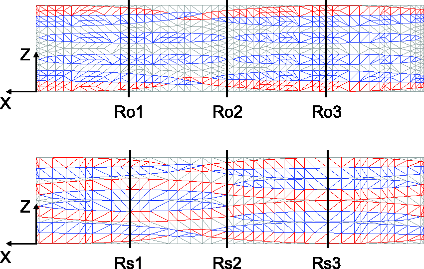
Analysis paths of the reference submodels.
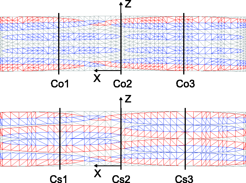
Analysis paths of the center submodels.
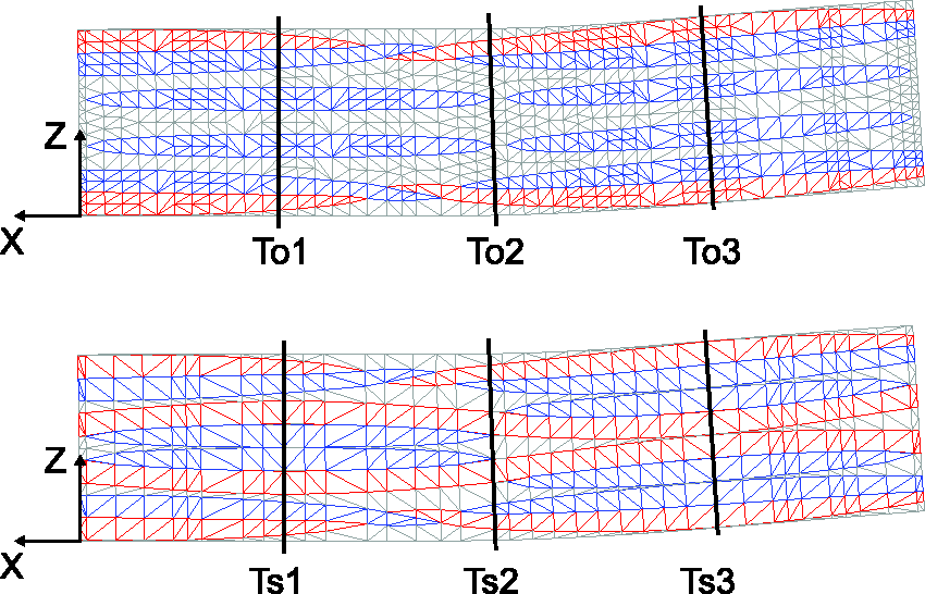
Analysis paths of the transition submodels.
According to Espadas-Escalante, 15 a similar procedure is used, so that the mesh is selected in the best achievable form, while taking the computation time into account. Also, a local mesh refinement is not performed. Nevertheless, it is possible to make a qualitative assessment of the stresses.
Numerical results
Initial numerical calculations on the global model supply the boundary conditions for the three submodels and the associated two variants. Consequently, the results of the global FE models are presented first. For the global model of the straight reference specimen a major principal strain of 3500
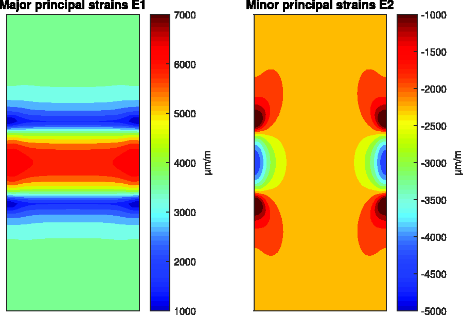
Major and minor principal strains for the global FE model of the specimen with half-wave imperfection.
In regions far away from the half-wave imperfection, major principal strains of 3800
Despite the fact that no convergence study is performed and consequently the absolute values are not proper, it is permissible to evaluate the stresses along the defined paths. The reference submodels, which obtained their boundary conditions from the straight reference specimen, are used to determine the relevant stress components caused by the free-edge effect. The relevant stress components are
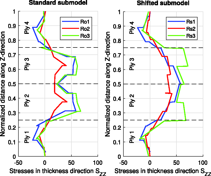
Through the thickness stresses
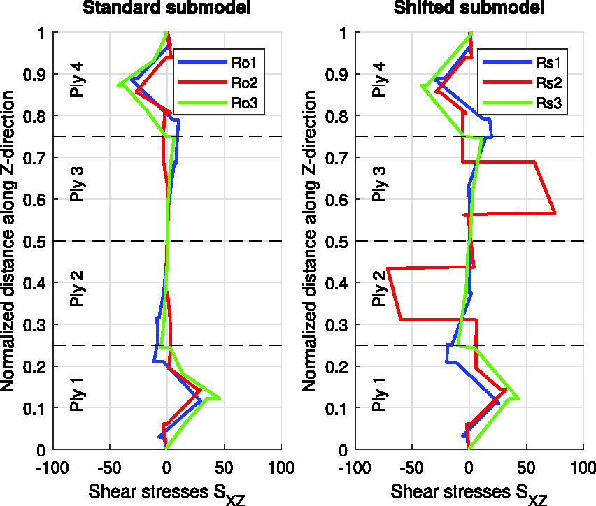
Shear stresses
Similar to the results of the reference submodels, the results for the submodels at the center of the half-wave are evaluated. The extracted paths of these submodels are shown in Figures 12 and 13. For the standard submodel and the shifted submodel, it is determined that the stresses
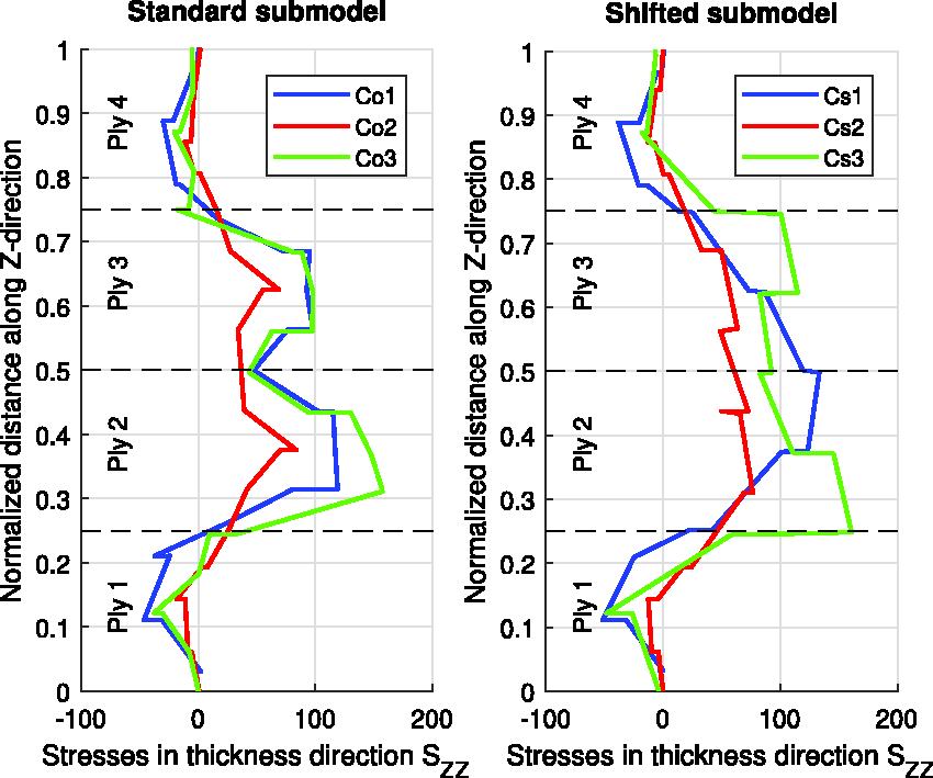
Through the thickness stresses
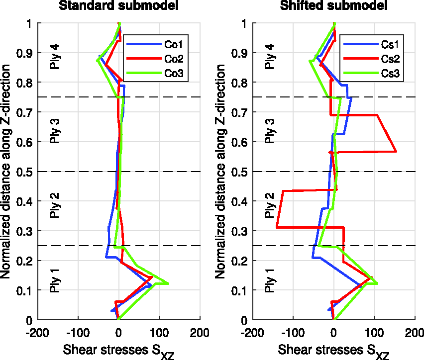
Shear stresses
The results for the submodels, which are created for the transition radius are shown as graphs in Figures 14 and 15. There are again no positive stresses
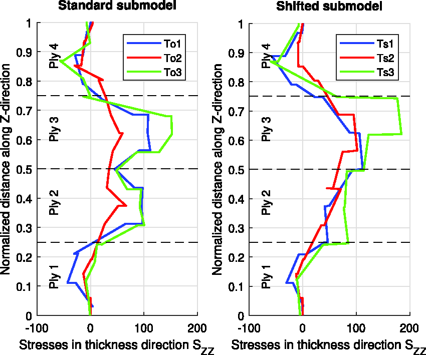
Through the thickness stresses
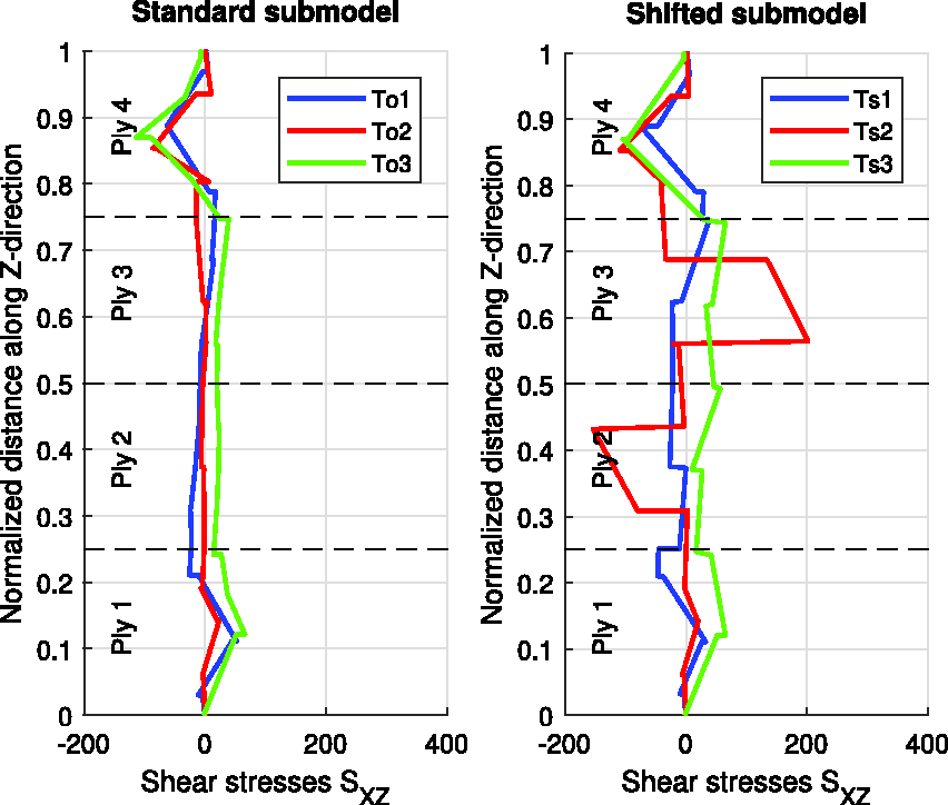
Shear stresses
Test results
3D-DIC measurements and the images of the digital photographic camera taken during the experimental tests are used to validate the results obtained from the numerical calculations. For each specimen the quasi-static ramp to
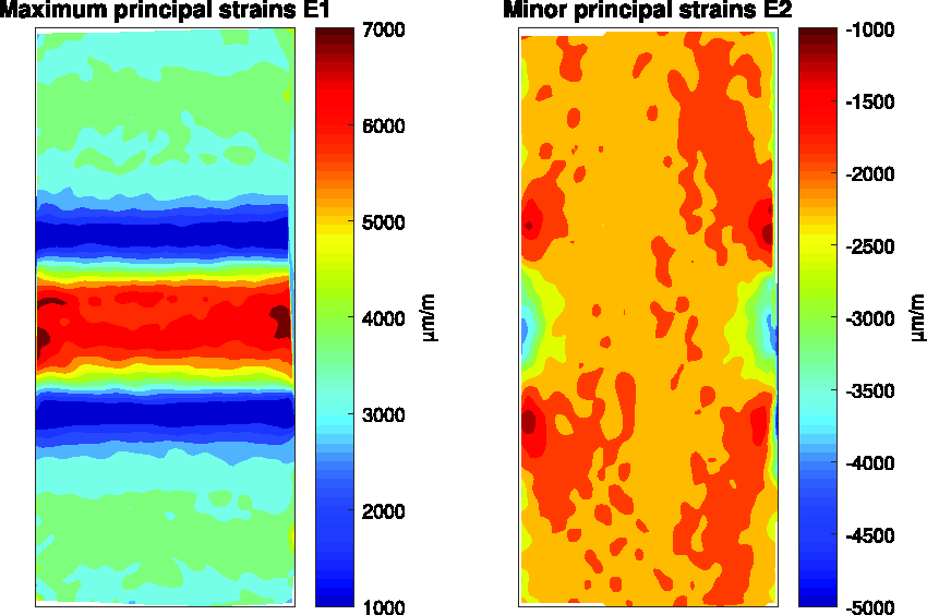
Principal strains for the specimen with half-wave imperfection.
The digital photographic camera documents the damage initiation due to the free-edge effect. The camera is focussed on one of the lower transition regions. For each tested specimen, pictures are taken in constant time increments. However, it should be noted that there are four transition regions and that the digital photographic camera only observes one of them. Thus, initial damage might occur earlier in any of the other transition regions. Nevertheless, all tested specimens show a similar behavior regarding the free-edge effect, such that for each load level it is sufficient to display the response of a representing specimen. In Figures 17 and 18 these obtained results are shown. In the pictures, damage initiation resulting from the free-edge effect can be identified. As the side of the specimens is also coated with an airbrushed speckle pattern it is easily possible to relate the individual images to the initial state. The cross section views are heavily magnified and rotated.
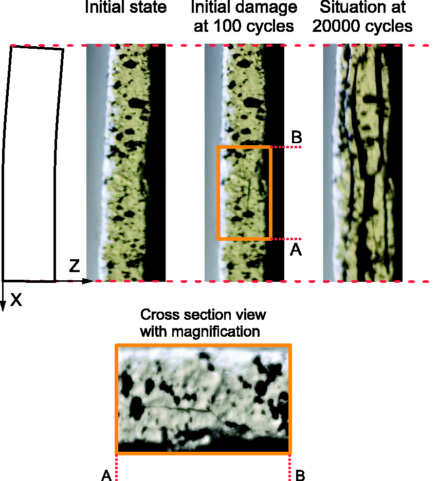
Damage initiation of a specimen at 80% load level.
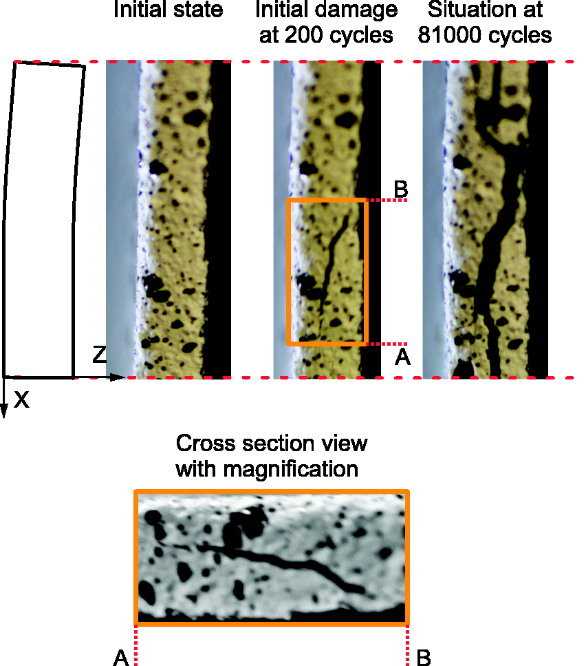
Damage initiation of a specimen at 75% load level.
For the specimen shown in Figure 17, where damage due to the free-edge effect is observed, damage initiation occurred after approximately 100 cycles. The high upper stress level of 80% of the tensile static strength causes initial damage in form of a crack. This crack is located inside ply 3 and between ply 2 and ply 3. As the number of cycles increases, further cracks occur. After 20000 cycles the majority of the plies at the free-edge of the transition radius are separated.
For the specimen, which was tested at 75% load level, damage initiation begins at roughly 200 cycles. Similar to the specimen tested at 80% load level, a first crack is located inside ply 3 and between ply 2 and ply 3. However, even after 81000 cycles no new cracks appear in the captured image area. This could be interpreted that crack saturation has been reached. Nevertheless, the final crack state was different for each specimen.
Discussion of results
The benign form of the half-wave imperfection and the selected manufacturing process prevent the formation of a resin pocket. Thus, the focus can be placed on the unsupported waviness, based on the assumption that the resin pocket has no effect on the free-edge effect under tension-tension fatigue loading. When comparing the numerical results of the specimen with half-wave imperfection with the according experimental data, the principal strain distributions as illustrated in Figures 9 and 16 show good agreement. The small differences could originate from local material inhomogeneities as well as from internal stresses introduced in the manufacturing process. However, the global FE model reflects the behavior of the real specimens and thus provides appropriate boundary conditions for the submodels, where the highest out-of-plane stresses
Comparing the experimental results in Figures 17 and 18 with the results of the submodels of the transition region in Figures 14 and 15, it is obvious that the highest normal stresses
Normal through-thickness stresses
With regard to the normal stresses in thickness direction
Interlaminar and intralaminar shear stresses
For a complete consideration regarding the location of the onset of the free-edge effect, the interlaminar and interlaminar shear stresses
Conclusions
In this study the influence of a geometrical half-wave imperfection on the free-edge effect was investigated for plain-woven carbon fiber reinforced plastics under cyclic tension-tension loading. For this purpose FE submodels were created, which were composed of matrix and fiber tows. In order to assign the correct boundary conditions to the submodels, global FE models of a straight reference specimen and a specimen with half-wave imperfection were created. The global FE model of the specimen with half-wave imperfection was validated by experimental tests, so that permissible boundary conditions were ensured. Since the DIC was not able to be focused on the free edge as a result of the small thickness of the laminate, an indirect validation had to be performed by means of surface strains on the frontal side. The two defined submodels with the two layup variants were placed at selected locations, whereby an intermediate step was performed in advance to shape the submodels into the desired form. This intermediate step was crucial for the two variants of the submodels placed in the curved transition area and in the middle of the half-wave imperfection. The third submodel was generated for a straight reference specimen, where again both variants were taken into account.
Defined analysis paths in the submodels revealed on the one hand the differences between the two variants, and on the other hand the distributions of the relevant stress components that caused the free-edge effect. Due to its geometry the specimen with half-wave imperfection was additionally stressed in bending during tensile loading, which was also reflected in the out-of-plane normal stresses
Since the location and occurrence of initial damage is now understood by experimental tests and numerical calculations, the next step is to develop a criterion, with which damage initiation and furthermore damage progression could be described. In addition, the influence on the lifetime, affected by the half-wave imperfection, will be investigated. Also the influence of different aspect ratios and ply orientations will be part of future investigations.
Footnotes
Declaration of Conflicting Interests
The author(s) declared no potential conflicts of interest with respect to the research, authorship, and/or publication of this article.
Funding
The author(s) disclosed receipt of the following financial support for the research, authorship, and/or publication of this article: This study was supported by the Christian Doppler Research Association, the Austrian Federal Ministry for Digital and Economic Affairs and the National Foundation for Research, Technology and Development.