
Abstract
Development of high-performance sandwich structures is particularly attractive for aerospace applications, where novel lighter materials and structures are object of extensive research. This work is focused on the design of a new high-performance Carbon FRP core as alternative to traditional periodic prismatic ones. The innovative core is designed as a 2D close-packing pattern of circular cells and manufactured by connecting pre-preg corrugated laminates in specific locations. The corrugated laminates are layered following an asymmetric sequence in order to generate residual thermal stresses within the core to enhance energy absorption and compressive properties. The distribution of the residual thermal stress within the core was numerically studied with a finite element model of the unit cell, in order to prove the positive contribution of the asymmetric layup on the mechanical properties and study the failure mechanisms of the unit-cell. Composite core samples were manufactured, and their mechanical properties were experimentally evaluated through compression, both out-of-plane and in-plane, and beam flexure tests. Results were compared in terms of specific properties with traditional aluminium honeycomb core, showing large increments of specific compressive strength (+84.6%), in-plane compressive modulus (over +500%), Specific Energy Absorption (+145%) and shear (>20%). The FEM model was validated against experimental compressive results, showing an error below 10%. The results show that the core is suitable for applications in novel high-performance sandwich structures, leading to numerous advantages in comparison to traditional cores, such as higher specific properties, manufacturability of complex sandwich structures and higher adhesion and compatibility with CFRP skins.
Introduction
Composite sandwich materials are largely diffused in several engineering sectors, such as automotive, aerospace and naval, and can be found in many applications as both primary and secondary structures. In these sectors, panels made of thin fibre reinforced polymers skins and cellular cores 1 are commonly used to achieve high mechanical properties with a reduced structural weight. Given their diffusion, research on new cores is in rapid development in order to design advanced sandwich structures. Traditional cellular cores are honeycomb (2D periodic prismatic cores),2–4 foam5–8 and truss materials.9–12 Despite the variety of research on truss cores thanks to the numerous possible combinations of 3D geometries and materials, 2D periodic prismatic cores, such as honeycomb cores, remain the preferred solution due to their relative high strength and stiffness, combined with a very low weight. Based on this, numerous researches are focused on the development of new kind of 2D periodic prismatic cores.
For instance, Bitzer 13 compared some of the common sandwich structures, showing that the honeycomb core has higher specific mechanical properties if compared to foam cores. An overview on the materials used to produce honeycomb cores (i.e. aluminium, Nomex, Kraft paper and fibreglass) and their manufacturing techniques is given in his work, and carbon fibre reinforced materials are mentioned as the first non-metallic core with shear moduli comparable to the aluminium honeycomb. Xiong et al. 14 provided a modified Ashby’s chart 15 that shows mechanical properties (density versus strength) of the most common sandwich cores, showing a gap between the maximum strength for existing materials and the maximum theoretical strength, which is going to be filled by the developing of lattice cores, including pyramidal composites and carbon fibre honeycombs. Russell et al. 16 asserted that fiber reinforced cores are the natural development for sandwich structures to increase the specific strength and stiffness. In their work, they studied the out-of-plane properties of a square honeycomb core made of carbon fiber reinforced polymer (CFRP) layers connected by mechanical and adhesive joints, providing results in terms of specific compressive strength that reside in the gap in the modified Ashby’s chart. Their work shows the importance of the development of new fiber reinforced lattice cores, thanks to their high specific properties, but highlighting the complexity in the prediction of their mechanical response and their sensibility to manufacturing defects.
With the aim of manufacturing high strength and low-density sandwich cores, many attempts to use fibre reinforced materials can be found in literature. Petrone et al.17–19 studied the vibrational performance and mechanical properties of honeycomb cores with different kinds of reinforcement, in particular flax fibres. They concluded that the use of long fiber reinforcement improves the mechanical performances, in particular compressive and shear modulus and strength (over +100%) but reduces damping (–40%) when compared to a polymer-only core. Integrated woven lattice cores, characterised by having skins and core woven together by the same fibre yarns, were designed, manufactured and experimentally characterised by Fan et al.20–23 and Brandt et al. 24 This kind of reinforcement leads to sandwich structures with a high skin-core debonding resistance, but the manufacturing process requires complex techniques and machines, limiting the design variability. Carbon fibres were also used as reinforcement for the manufacturing of Kagome,25,26 square,16,27,28 egg and pyramidal29–31 and other lattice32,33 cores, demonstrating excellent structural characteristics.
Difficulties in manufacturing continuous carbon fibres reinforce lattice core has limited the study of this kind of structures. Alia et al. 34 manufactured and tested a CFRP honeycomb core using the vacuum-assisted resin transfer molding method (VARTM), studying the compression and specific energy absorption properties. Different directions and typologies (unidirectional and fabric) of fibres were analysed, and results showed compression strengths of up to 35 MPa and specific energy absorption values of 47 kJ/kg.
One of the advantages in the use of CFRP materials for the manufacturing of the core is the increment of the in-plane properties, that are one of the main complications with the use of the traditional honeycombs. 35 Those properties become important during the manufacturing, where significant in-plane loads may occur, for example during autoclave curing processes of sandwich structures, leading to costly part rejects and limitations in the design of complex geometries, as studied by Hsiao et al. 35 The in-plane mechanical properties of 2D periodic prismatic cores are also strongly dependent on the cell geometry and distribution, as shown by Oruganti and Ghosh 36 In their work, results of finite element method (FEM) analysis are used to study and compare creep deformation of different cell geometries, concluding that close-packing circular cell honeycombs (Figure 1) have higher mechanical properties than the hexagonal ones, due to internal constraints of the cells. The reason of the larger diffusion of hexagonal cell honeycomb cores is to be found in manufacturing limits: unlike hexagonal cells, a compact distribution in the space of circular cells would leave gaps, highlighted in red in Figure 1, that would be difficult to fill if metals are used as material. In addition, hexagonal honeycombs can be easily manufactured by folding and gluing thin strips of materials.
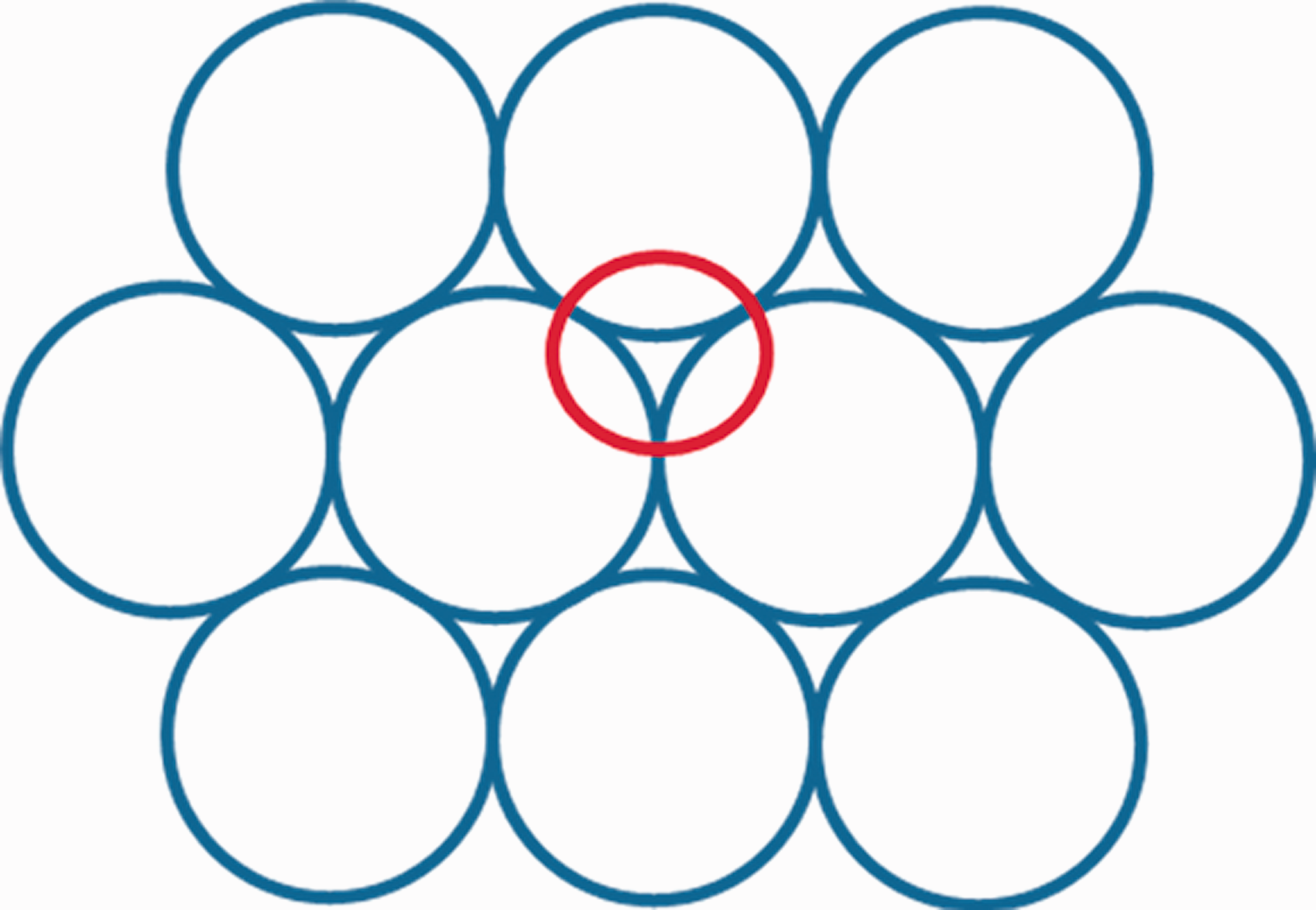
Circular cell honeycomb distribution. The red circle highlights the gap between adjacent cells.
Despite the numerous benefits of fiber reinforced polymers, an issue associated with the use of carbon fibres parts is that CFRPs show low energy absorption due to their complex failure modes (fibre fracture, interlaminar debonding and matrix cracking).37–39 To increase the impact strength of CFRPs, many approaches have been investigated: reinforcement of carbon fibres–matrix interface;40,41 stitches insertion along the laminate’s thickness;42–44 hybridisation of composites mixing reinforcement materials;45–47 insertion of metal wires within laminates staking sequence.48,49 In this context, the use of residual stresses in the structure to increase energy absorption has attracted the attention of several researchers over the last decades. Indeed, the generation of residual stresses in thin structures can lead to the existence of two stable configurations, as explained by Scarselli et al, 50 and the transition between the two requires energy, that can be absorbed from an external load. The residual stresses can be designed to act in the same direction of the predicted external load but with an opposite sign, as it happens with prestressed concrete. 51 Winkelmann et al. 52 analysed the concept of composite bistability and showed its advantages as energy absorption mechanism for tensile loading, basing on previous works by Whitman and Saponara 53 on metal structures and woven composites. Kebadze et al. 54 investigated the mechanics of the bistability induced by plastic bending of cylindrical shells and provided an analytical model able to predict the deformed shape. Recently, thermally induced bistable composite structures have been used in aerospace structures as morphing components50,55,56 for the aerodynamic control of the aircraft.
Hyer 57 was the first to study the circular cylinder bistable shape of composites, observing how this phenomenon happens only for thin asymmetric laminates, while thick laminates follow Classical Lamination Theory 58 that predicts a saddle shape. Later on, Dano and Hyer 59 provided a full analytical model to predict the curved shape of thin asymmetric laminates, such as [0/90]T. Daynes et al. 60 extended Heyer studies to symmetric laminates.
The literature shows that the interest in bistability and thermal prestresses in composite laminates is growing and many studies are emerging in the field of morphing structures, however the use of thermal prestress as an additional mechanism to improve energy absorption is a promising unexplored field.
Based on these premises, the aim of this work is to develop, manufacture and characterize a new lattice core characterised by high mechanical properties and based on three features: use of CFRP material circular cell honeycomb design application of thermal pre-stresses
The new core, herein referred to as circular prestressed carbon core (CPCC), is designed to obtain high specific stiffness and strength, along both in-plane and out-of-plane directions, to be employed for sandwich structures in high performance applications. To obtain this, asymmetric CFRP prepreg strips are corrugated and connected in order to obtain the circular honeycomb cells. Both analytical and FEM analyses are presented to study the residual thermal stress distribution in the structural unit-cell of the core. The numerical model of the unit-cell is successively expanded to the whole sample to simulate mechanical compressive tests and study the influence of manufacturing defects on the mechanical responses. In order to characterise the structure, the designed core is manufactured and experimentally studied through out-of-plane and in-plane compression and three-point bending tests. The results are compared with the one obtained from the same experimental tests performed on a traditional aluminium honeycomb core in order to have a comparison with a core widely used for manufacturing of sandwich structures.
Core design
The structure of the CPCC core consists of corrugated strips of material connected in precise points to create a pattern geometry. Two layers of prepreg are used to create the corrugate strips, in a [0,90] fiber configuration. An advantage in the use of resin impregnated material is in the filling of the previously mentioned empty spaces between the adjacent cells and thus the increase of the contact area between the strips, as schematically represented in Figure 2(a). The main geometrical difference with the traditional honeycomb structure is in the cell: a circular cell is used instead of the hexagonal one during the manufacturing of the CFRP core. Using a circular cell it is possible to avoid sharp edges that may be points of stress concentration, especially for fibre reinforced materials, 61 as highlighted in Figure 2(b).
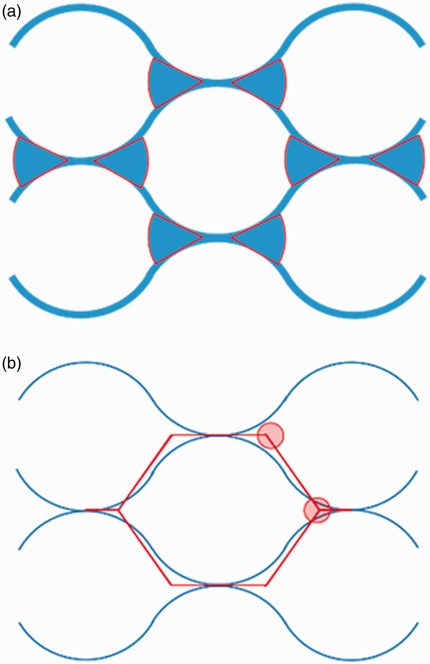
Circular cell honeycomb structure: (a) detail of the intercellular spaces filled by the resin; (b) comparison with hexagonal cell and detail of the avoided sharp corners.
The unit-cell design parameters and directions used in this work are illustrated in Figure 3. The value of s derives from the nominal value of the cured prepreg thickness (0.211 mm), while d is the radius of the steel cylinders used to give the shape of the cell and the b is a geometrical parameter (half of the distance between two adjacent cells) deriving from the close-packing pattern.
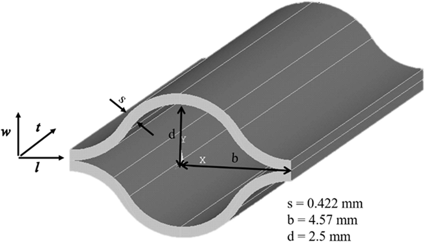
CPCC unit cell.
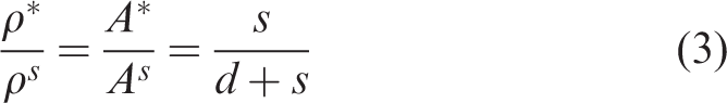
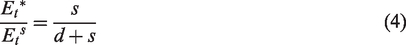
Analysing a quarter of the unit cell, it is possible to approximate the geometry to an area composed of two parallel curves vertically shifted by s. Based on this, it is possible to calculate the area, and thus the core density, of the quarter of unit cell with the following equations


Using the design values showed in Figure 3 and the nominal values of


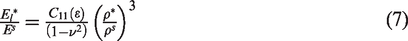
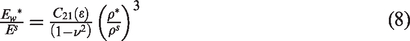
The estimated value of elastic modulus in equation (6) is to be considered as an upper reachable limit for the designed core, as it is calculated using the nominal material properties and fiber percentage provided by the prepreg manufacturer for optimal conditions of curing and on the assumption of the perfect alignment of the fibers along both 0 and 90 directions. The analytical evaluation of the elastic shear moduli is more complicated, due to the geometrical complexity and non-uniformity of deformations of the cell walls, and can only be evaluated numerically. 1
Chung and Waas
62
provided some analytical estimations of the in-plane elastic properties of elliptical cell honeycombs. Their calculations were made under the approximation of small
where
Gibson et al.
1
provided the equations for the in-plane elastic moduli for hexagonal honeycomb structures as follows
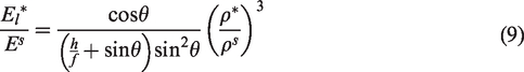
Analysing the CPCC unit-cell structure along the two in-plane directions, it is clear that the response of the structure to a compressive load under the l and w directions is different. Along the w direction, the load is meanly supported by the circular part of the unit cell, thus giving a mechanical response similar to the elliptical honeycomb. On the other side, when the cell is loaded along the l direction, the predominant mechanism is the compression of the corrugated plies, thus similar to the hexagonal honeycomb. The geometrical approximations and relative parameters are given in Figure 4. Using the equations (8) and (9), the following values can be estimated for the in-plane elastic moduli


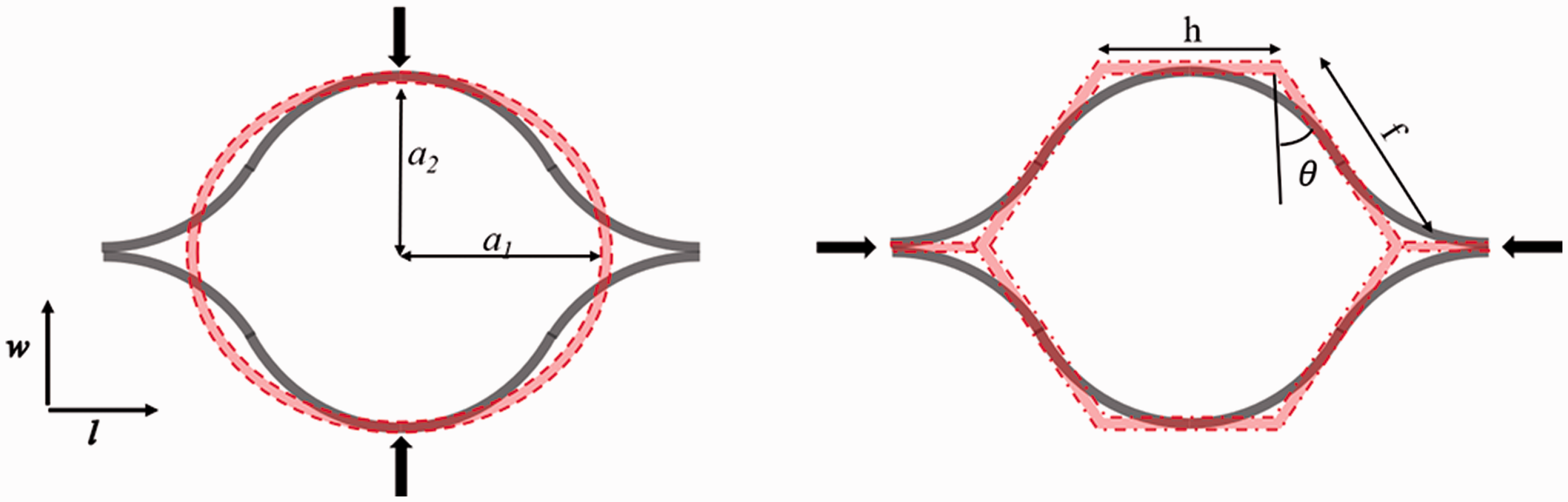
Geometrical approximations of the unit cell under in-plane compressive loads.
It is important to highlight that the estimations provided here are based on assumptions of perfect material and ideal boundary conditions. These values will be used to validate the FEM model of the unit-cell with ideal parameters and boundary conditions.
Analysis
In this section, some analytical considerations and numerical studies of the CPCC core are illustrated. First, the analytical equation governing the bistability of curved unsymmetric laminates is described. Then, the residual stress and strain fields are numerically calculated using a FEM analysis of the single wall and single unit cell. The influence of the residual stress over the mechanical properties of the unit-cell is evaluated by simulating the mechanical tests and validated through comparison with the analytical calculations of the elastic moduli provided in the previous section. Successively, the FEM model is expanded to a whole CPCC sample and compression tests, both out-of-plane and in-plane, are simulated.
Bistability description
Considering a traditional CFRP, the coefficient of thermal expansions of the resin (35–65 ×·10−6/K) is significantly different from that of the fibres (∼0/K). 63 As a consequence, in a laminate with a unsymmetric fiber orientation, the difference of thermal expansion of the laminae will generate residual stresses after the cure that will lead to a not-flat shape. For an unsymmetric composite laminate, the classical lamination theory (CLT) predicts a saddle shape at room temperature after the cure; 64 however, the same theory does not apply for thin rectangular laminates, where thermal stresses lead to two cylindrical stable shapes, as demonstrated by Hyer 57 and illustrated in Figure 5(b) and (c). While the saddle shape is characterised by a curvature along both in-plane directions (x and y in figures), the two cylindrical configurations present curvature along only one direction. These configurations are both stable at room temperature, and laminates can suddenly pass between the two if a sufficient external moment is applied, leading to the so-called snap-through phenomenon.
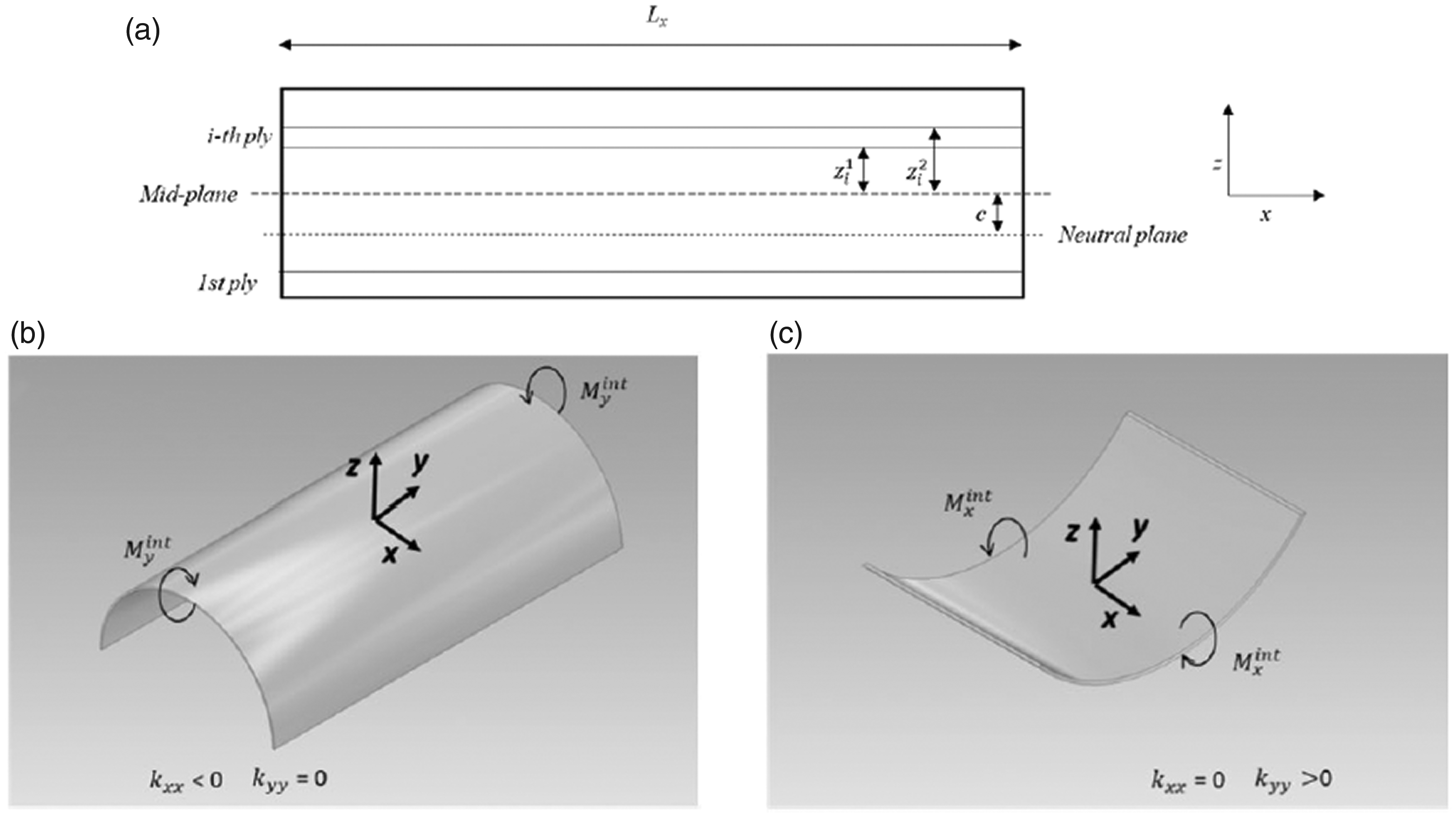
Geometry of the composite laminate and axes orientations: (a) cross-section of flat configuration; (b) first stable configuration with curvature along the y-direction; (c) second stable configuration with curvature along the x-direction.
The most used analytical model to correctly predict these stable shapes of bistable composite laminates is the Rayleigh-Ritz energy method.59,65,66 Ryu et al. 67 presented the explicit model to estimate the cured curvature and strain fields of a unsymmetric cross-ply laminate in [0,90] configuration, cured over a curved mould. Lee et al. 68 expanded this model to evaluate the laminate residual moments, and thus the snap-through load, applying the classical laminate theory. Given the similarity of the single cell wall of the CPCC core to the case studied in these two works, these analytical models are briefly described in this section.
The explicit model proposed by Ryu et al.
67
to evaluate the Green-Lagrangian strain field and strain energy function is based on the following three assumptions: The existence of a linear constitutive equation between the Green-Lagrangian strain and the second P–K stress (infinitesimal strain) Neglection of the edge effects (constant curvature) Kirchhoff–Love thin plate assumption (small thickness-to-side ratio)
As mentioned above, the shape of the stable configuration may be of two kinds: saddle, that is when both sides of the laminate are curved at the same time, or cylindrical, when only one of the two sides is curved. In this work we focus only on the second case, cylindrical shape, that is the predominant shape when the laminate is thin and presents a side sufficiently longer than the other one. Indeed, when thin composites present a rectangular plane shape, the strain energy of the laminate in the cylindrical configuration is lower than the one in the saddle shape, and thus it is the stable one. In a cylindrical shape, only one of the two curvatures, either
The Rayleigh–Ritz energy method is based on the minimization of the total potential energy

where
Finite element analysis
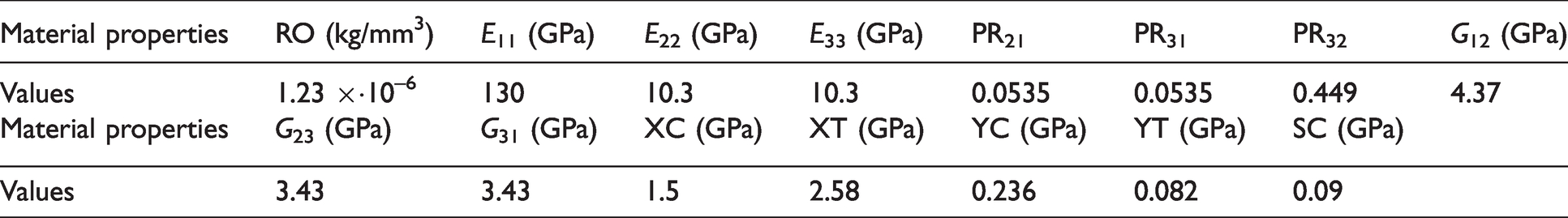
3D implicit FEM models of the composite core were developed using Ansys®/LS-Dyna® software. Each ply was modelled using fully integrated 0.211 mm thickness shell elements (type 16), which uses a local element coordinate system, defined as in the Belytschko-Tsay element, 69 that rotates with the material. The properties listed in Table 1 were used to define the orthotropic material using a Chang matrix failure criterion 70 (MAT_54_ENHANCED_ COMPOSITE_DAMAGE). Tie-break contacts (AUTOMAIC_SURFACE_TO_ SURFACE_TIEBREAK) were applied at plies interface in order to simulate interlaminar contacts, whose properties are listed in Table 2.
Material properties (subscripts 11 refer to fiber direction, 22 to in-plane direction perpendicular to the fibers and 33 through the thickness): RO density; E modulus of elasticity; PR Poisson’s ratio; G shear modulus; XC and XT longitudinal compressive and tension strengths; YC and YT transverse compressive and tension strength; SC shear strength.
Tie-break contact properties.

FS and FD: static and dynamic coefficients of friction; NFLS: normal failure stress; SFLS: shear failure stress.
The numerical study started with the analysis of a simple curved double layer of CFRP material, that is half of the CPCC unit cell (Figure 6). The structure was modelled as two layers of shell elements. Periodic conditions were applied to the two sides of the model in order to simulate the presence of the adjacent cells.
FEM model of the unit cell wall with fiber orientation [0 (red), 90 (blue)].
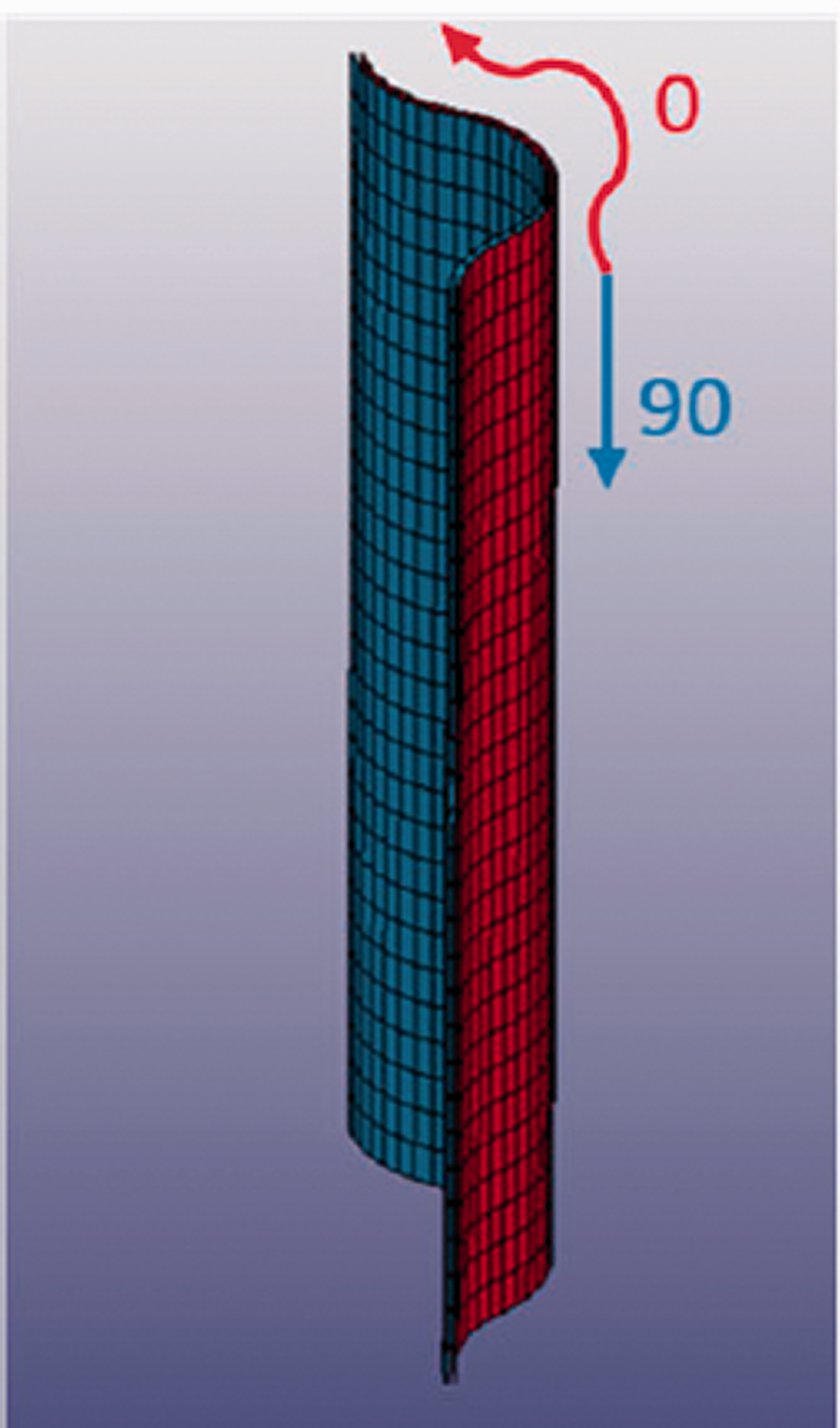
A coupled thermal-structural FEM analysis was performed on the model simulating the cooling cycle, lowering the temperature from 130 to 5°C in 1 s in order to generate thermal stresses. The model is expected to fail for buckling when loaded under out-of-plane compression. In such a kind of failure, a side of the structure will be subjected mainly to tensile stress, while the opposite side will be under compression. Based on this, the model is expected to have different mechanical responses in function of the order of the fiber orientations of the two shell element layers due to the anisotropy of the material. Two fiber configurations were considered: [0,90] and [90,0], where the 0° is the orientation along the wall curvature and the 90 along the vertical direction. In the nomenclature, the first orientation from the left is referred to the external shell layer (the red face in Figure 6).
As it is possible to see from Figure 7, that shows the vertical component of stress distribution after the structural-thermal analysis, there is a difference in the stress distribution between the [0,90] (Figure 7(a)) and [90,0] (Figure 7(b)) configurations, as expected, but in both cases the stress is positive (tension) in all the elements. This tension stress will act against the compression stress of the external load.
Thermal stress (GPa) t-direction component for (a) [0,90] and (b) [90,0] configurations.
The stress status and deformed shape of each element after the structural-thermal analysis were imported in a new FEM model to perform structural tests. In order to study the influence of the residual stresses on the mechanical properties of the part, an out-of-plane compression test was simulated.
The displacement of the bottom nodes was constrained in all the degrees of freedom (DOF), while the top ones were constrained only in the in-plane DOF and a vertically prescribed motion of 0.5 mm/min was applied to compress the structure. The boundary conditions are illustrated in Figure 8, where blue nodes are constrained in all DOF, red are constrained along the in-plane directions and have a prescribed motion along the vertical direction and the yellow nodes represents the period boundaries. A mesh convergence study has been performed at this stage, in order to determine the number of elements required along the direction of load to obtain results independent from the mesh size, basing the analysis on the failure load values. An optimal number of 30 shell elements (side dimension 0.75 mm) along the direction of load was selected, which lead to a total of 1920 elements and 2046 nodes.
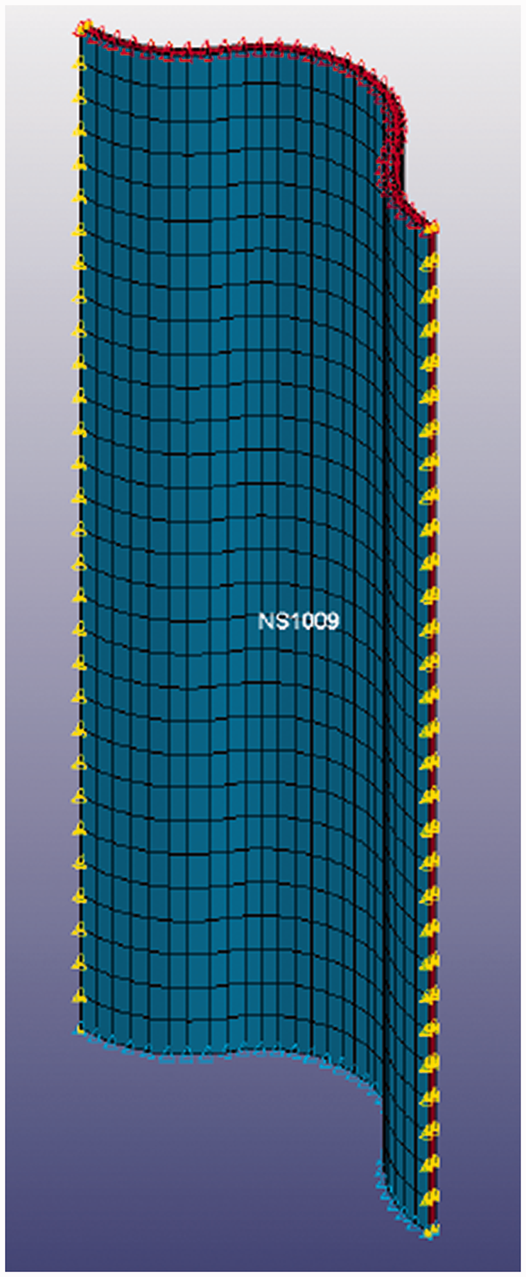
Cell wall model boundary conditions. Blue nodes (bottom): all DOF constrained; red nodes (top): in-plane DOF constrained and out-of-plane prescribed motion; yellow nodes (sides) periodic conditions at all DOF.
The simulation was also performed on the same models without applying any kind of prestress, in order to simulate the material manufactured following traditional slow cooling down process. Indeed, without the fast cooling down process, the material has the time to adapt to the thermal deformations, relaxing the residual stresses. For all the 4 combinations ([0,90] and [90,0], with and without prestresses) the failure occurred for buckling of the cell wall. In Figure 9(a), the load displacement curves for the [0,90] configuration with and without residual stresses are compared. The mechanical responses of the two models are different: the unstressed structure presents one failure at 0.87 kN, after which the load decreases, while the prestressed one shows a second increment of load after the first failure due to the bistability of the structure, which occurred at a value 15% lower than the unstressed. The numerical results show that at the time of the second failure, a sudden displacement of the structure occurs in the same location of the buckling failure, suggesting the presence of the snap-through phenomenon between the two stable configurations. The phenomenology of the event, illustrated in Figure 9(b), suggests that after the begin of the buckling failure (a), the external force works against the residual stresses (b) that are in opposite direction to the stresses generated by the buckling. This creates a new increment of the load carried by the structure, until the compressive stresses overtake the residual stresses (c), generating the sudden displacement (d and e) due to the bistability. It can be argued that that the residual stresses contribute in two ways for the [0,90] configuration: they reduced the ultimate load by 15% but created a second load peak and a snap-through event, that improves the absorbed energy (+10%).
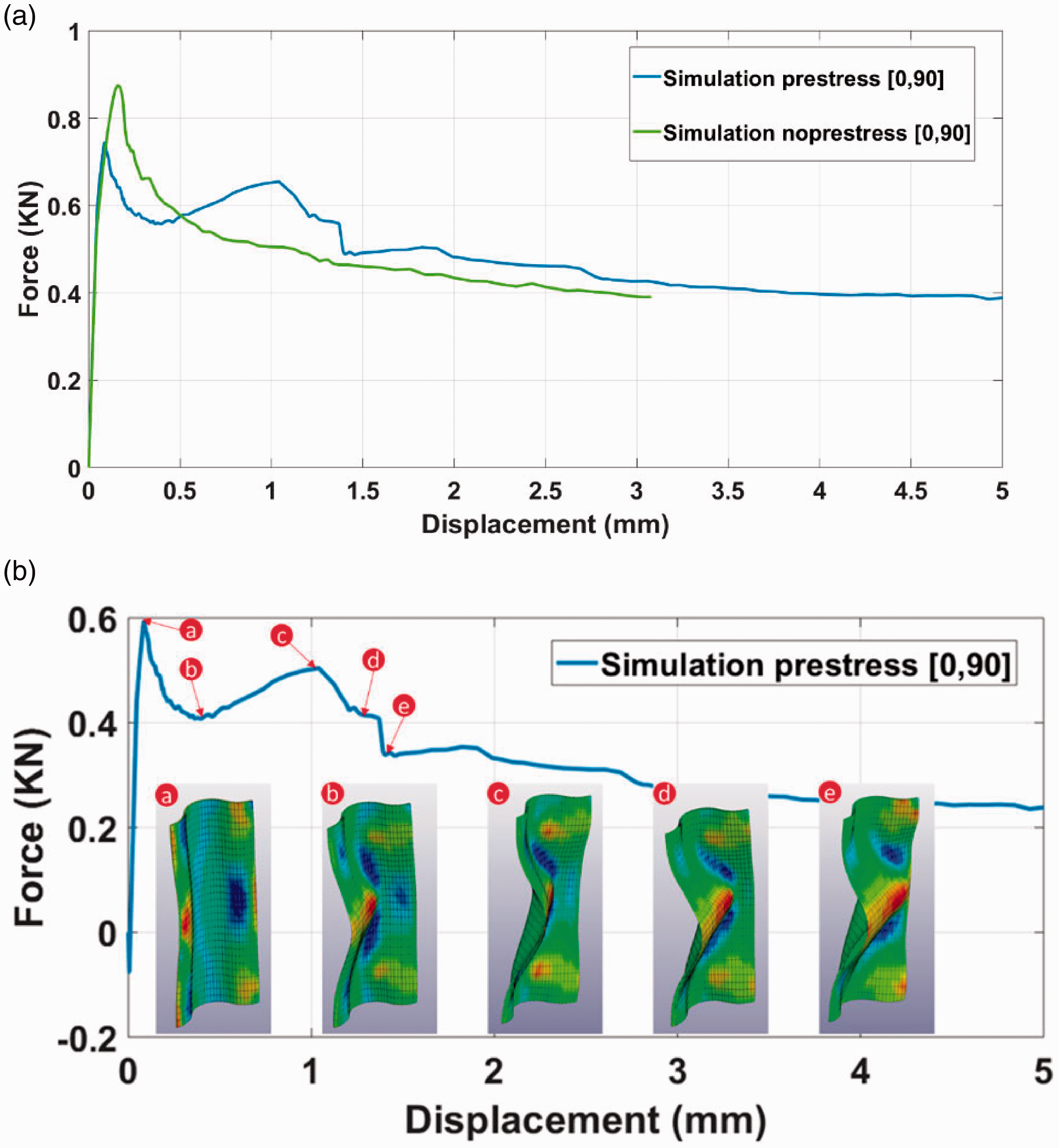
(a) Force-displacement curves from FEM analysis on prestressed and not prestressed unit cell wall model in [0,90]; (b) details from FEM analysis results on pre-stressed [0,90] model.
On the other side, the ultimate load for the [90,0] configuration is increased by approximately 19% due to the presence of the residual stresses, as it is possible to see from Figure 10. In this case, the shape of the two curves is very similar, but with a difference in terms of carried load. Given that the snap-trough depends on the fiber orientations, in this configuration the phenomena is not visible probably because the residual stress is overtaken by the external stress before the buckling failure happens. This means that the residual stress contributes only on the ultimate load, working against the compressive stress, but without any snap-through phenomena.
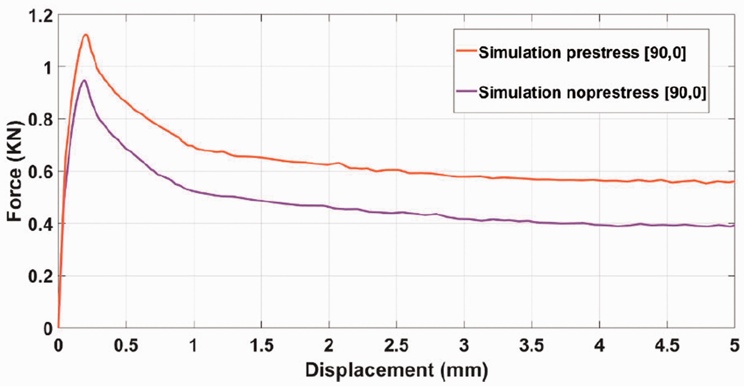
Force-displacement curves from FEM analysis on prestressed and not prestressed unit cell wall model in [90,0].
The clear difference in behaviour between the [0,90] and [90,0] configurations can be attributed to the asymmetry of the geometry and the different properties of the two fibers orientations. Given that the buckling failure creates compressive and tensile stresses on the two opposite sides, the response of the structure strongly depends on the mechanical properties of the two layers under these two kinds of load, which are very different between 0 and 90° layers. Therefore, if the layer on the internal side, where the tensile component of the buckling stress acts, is the 90° one ([0,90] configuration), the mechanical response is different from the [90,0] configuration, where the internal layer is the 0° one. This difference leads to two different buckling failures: towards the centre of curvature for the [90,0] and towards the external side of the curvature for the [0,90]. The direction of buckling for the [90,0] is the same direction of the snap-through, which therefore cannot happen. This explains the similarity of the two curves in Figure 10 and the absence of sudden displacement episodes.
After the analysis of the residual thermal stress distribution and compressive behaviour of the single wall, the analysis was extended to the unit-cell. The unit-cell of the circular honeycomb structure is composed of two cell walls attached to each other. For the FEM model, in order to take into consideration the mechanical properties of the contact between two adjacent cells, the unit-cell has been considered as two half-cells, as shown in Figure 11, leading to a total of 3840 shell elements and 4092 nodes. From an analytical point of view, for the evaluation of the elastic properties, this unit-cell is the same as the one showed in the previous section (Figure 3), and thus the results in terms of elastic moduli can be compared. In order to have symmetry, and thus symmetric residual stresses, two configurations are possible: [0,90]s (Figure 11(a)) and [90,0]s (Figure 11(b)). The same boundary conditions and properties of the single cell wall model were used.
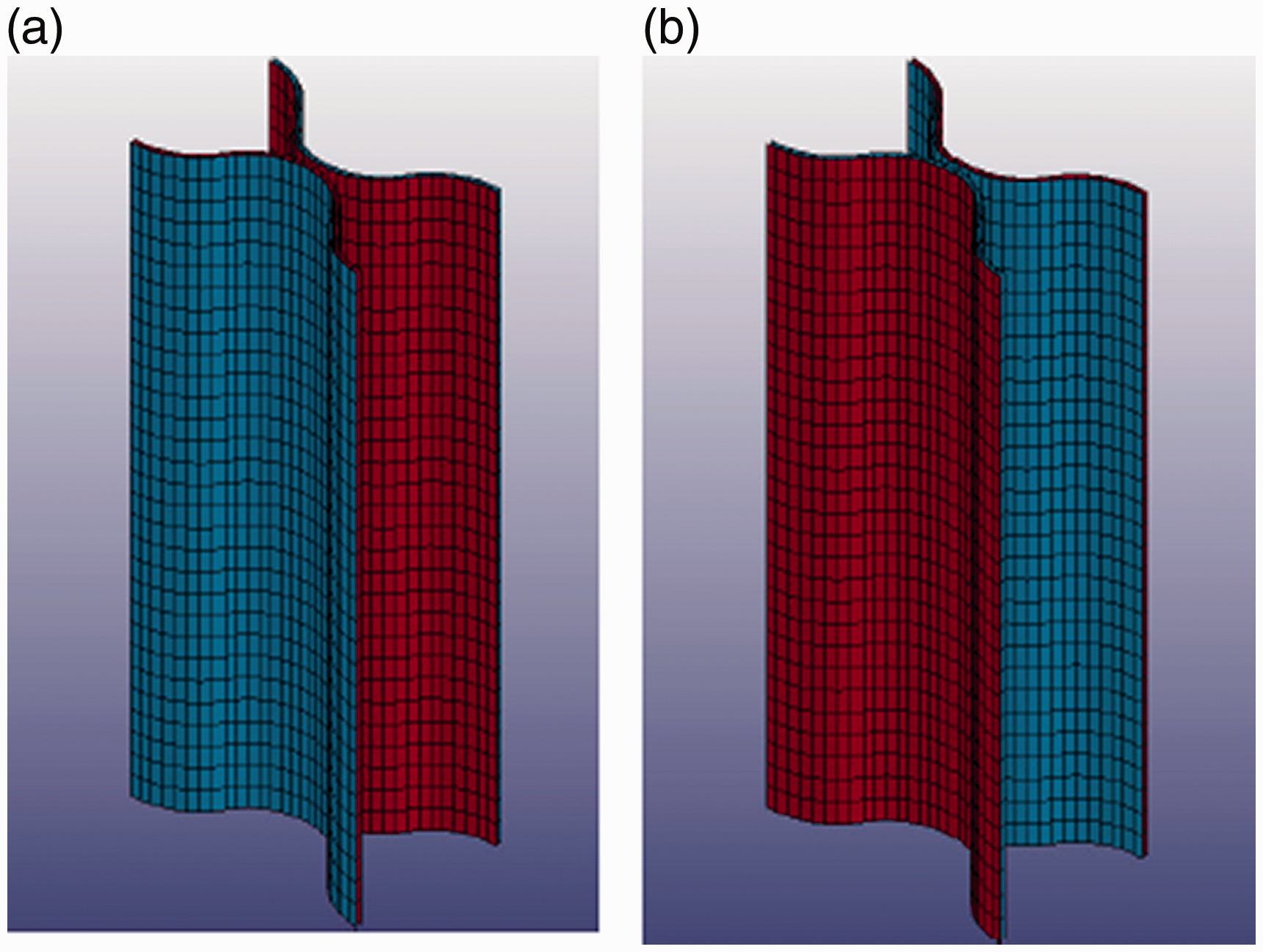
FEM model of the unit cell in a) [0,90]s and b) [90,0]s configurations. In red the 0 and in blue the 90 fiber orientations.
As for the cell wall FEM models, the unit cells were first modelled under thermal cycle and then the residual stresses imported in the structural analysis in order to simulate a compression test.
When in the unit-cell configuration, the behaviour of the [0,90] wall changes, as it is possible to see in Figure 12(a) where the load displacement curves are plotted. When the [0,90] wall is attached to a symmetric wall to form the [0,90]s unit cell, the compressive ultimate load of the prestressed structure is higher than the unstressed one by 17.3%. In this case, no snap-through phenomena are shown by the numerical results. However, it is possible to say that when the thermal stresses are applied to the [0,90]s structure, they improve the ultimate load, but no snap-through events are shown, leading to a load displacement curve with a similar shape of non-prestressed one.
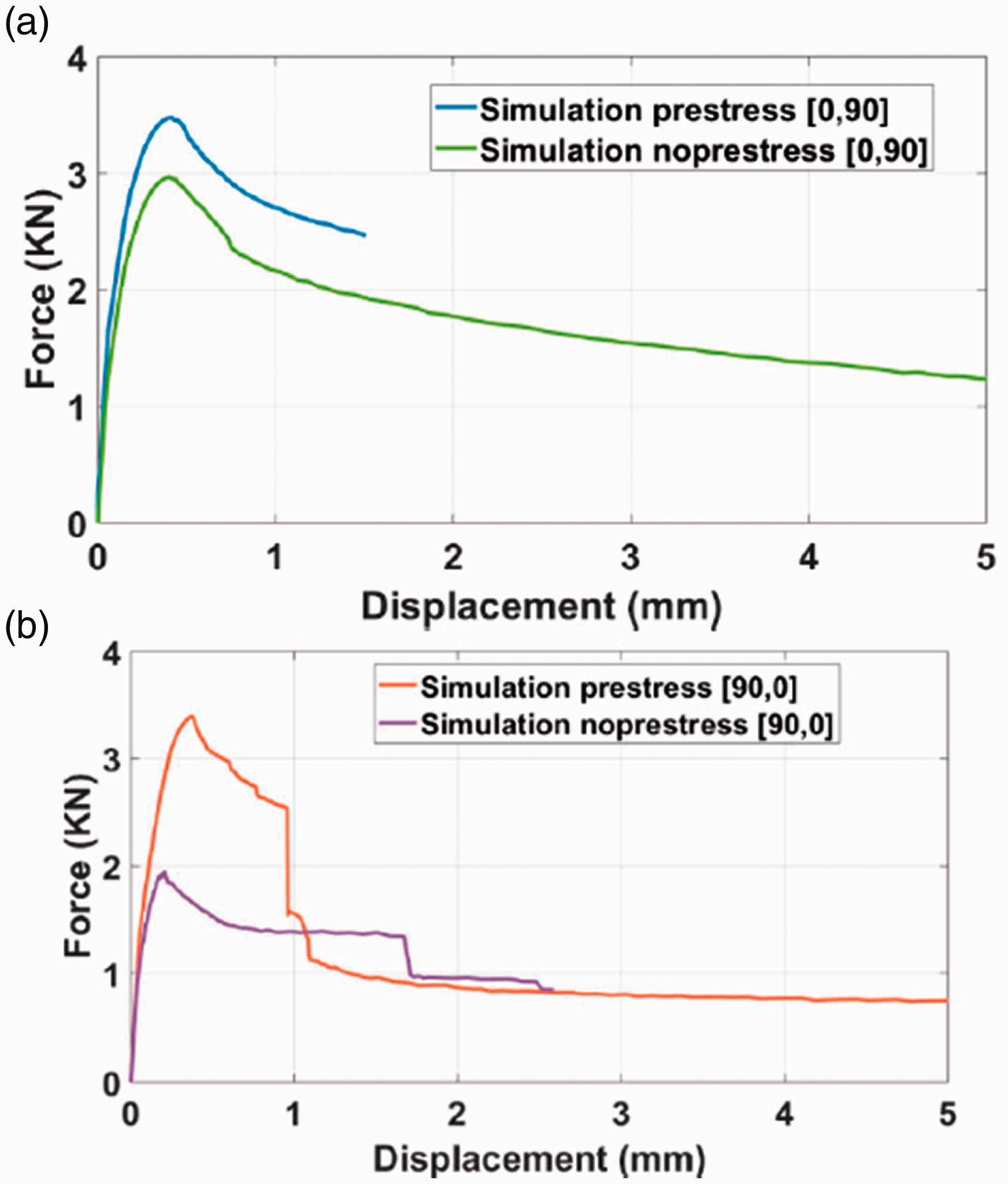
Force-displacement curves from FEM analysis on prestressed and non-prestressed unit cell model in a) [0,90]s and b) [90,0]s configurations.
Totally different is the mechanical behaviour of the [90,0] wall when modelled in the symmetric structure [90,0]s. As it is possible to see from the plot in Figure 12(b), there is a very large increment in terms of ultimate load carried by the unit-cell when compared to the non-prestressed one (+74.6%) and a snap-through event in correspondence with a 1 mm displacement.
Comparing the results of the single cell walls and the unit cells, it is possible to see how the stress strain curves of the [90,0]s is similar to the [0,90], showing a substantial difference between the prestressed and unstressed curves, while [0,90]s showed a response similar to the [90,0] configuration. This can be explained by analysing the position of the 90 layers in the two configurations. In this layer the reinforcement is orientated along the vertical direction, therefore is the layer that carries most of the load. As it is possible to see in Figure 13, in the [0,90]s configuration the 90 layers are divided by the 0 ones, and thus respond as separated structures. On the other hand, in a [90,0]s the 90 layers are connected in the centre of the cell, and therefore fail as one layer, optimising their mechanical respond. The buckling failure in the [0,90]s can happen in both directions (bistability), depending on local instabilities such as material defects.
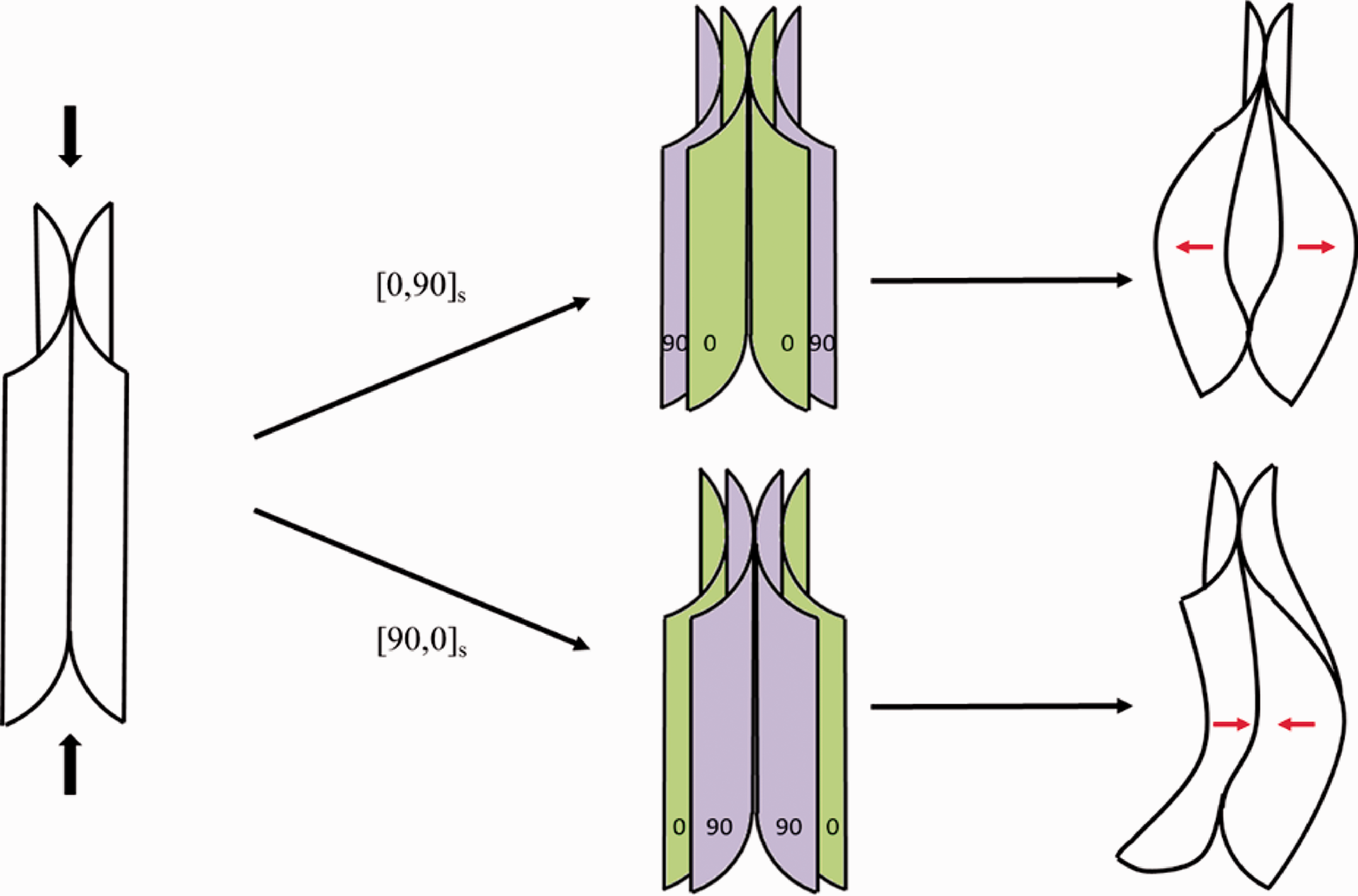
Bistable buckling failures of unit cells.
Unlike the cell wall cases, both symmetric unit-cell configurations showed improvements in terms of ultimate load. Particularly interesting is the case of [90,0]s where, in addition to an increment of 74.6% of the maximum load, larger values of absorbed energy (area below the curve) have been shown from results, and it is possible to see an actual bistability of the structure.
From the unit-cell FEM analysis results, it is possible to conclude that the residual stresses generated from a fast cooling cycle lead to improvements in terms of out-of-plane mechanical properties of the core and can generate additional energy absorption phenomena. In order to obtain the symmetric unit-cells, an alternate fiber orientation that creates a symmetric lamination at the joining points of the circular honeycomb structure is needed, as described in “Materials and methods” section. Using the alternate fiber orientation, the core will include both [0,90]s and [90,0]s configurations.
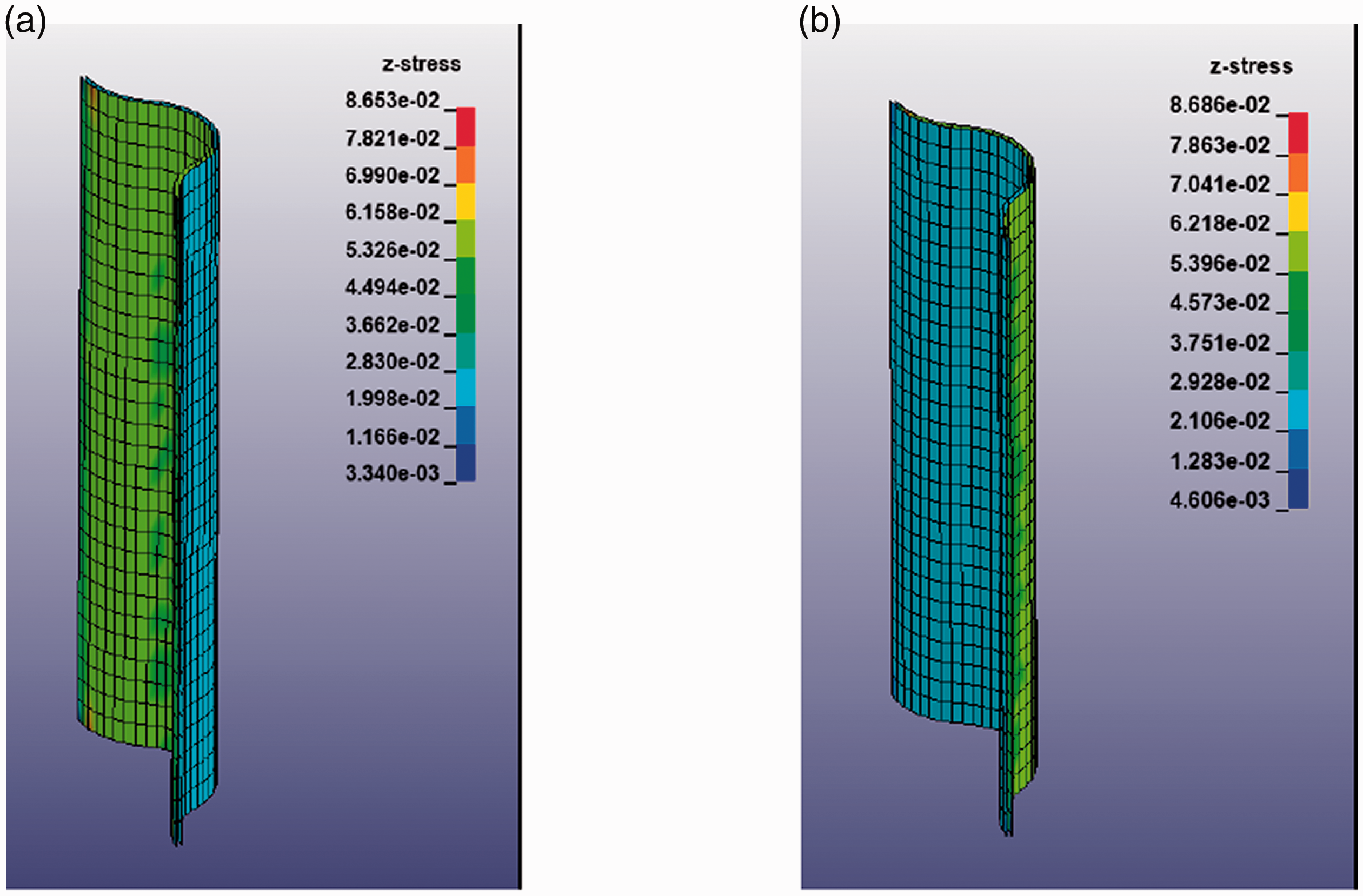
In order to compare the numerical results with experimental tests, the unit-cell FEM model was repeated in the space to obtain the CPCC sample FEM model, which for the compression out of plane test have dimensions of 50 × 50 mm leading to a total of 57,600 elements and 58,317 nodes. As for the unit-cell, the residual thermal stress distribution was evaluated and results for the t direction component of stress are showed in Figure 14.
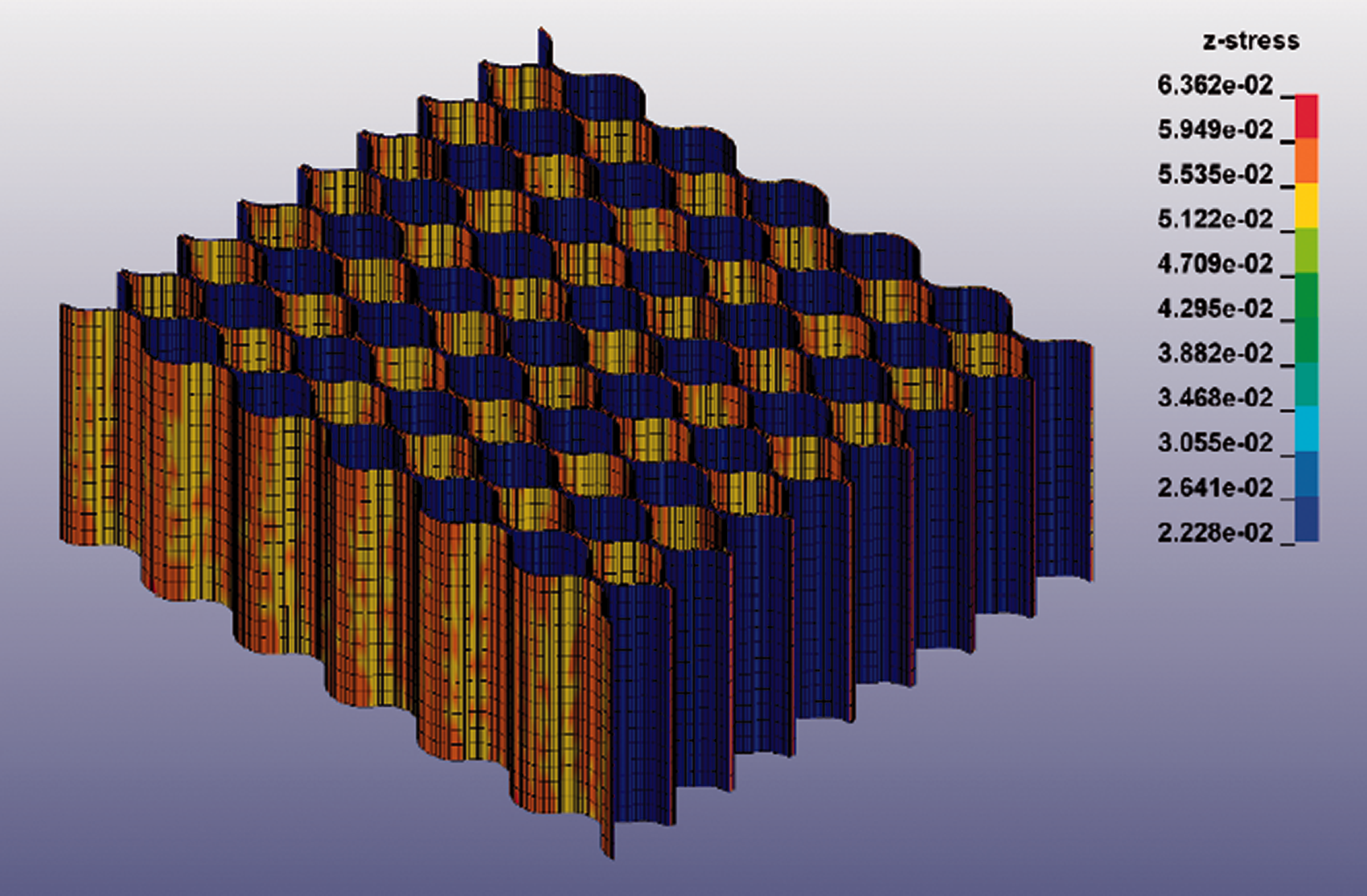
Thermal stress (GPa) t-direction component.
The compression out-of-plane test was simulated modelling two steel plates at the top and bottom of the sample. Given that deformations in the steel were negligible and not of interest, simple elastic material (MAT_001_ ELASTIC) was used, with an elastic modulus of 200 GPa and Poisson’s ratio of 0.3. The bottom plate was constrained in all the DOF, whereas a prescribed vertical displacement was applied at the top plate. An automatic contact (AUTOMATIC_ SINGLE_SURFACE) has been used between the steel plates and the core, with friction coefficients of 0.3 (static) and 0.2 (dynamic). Given that half of the fibers are loaded axially, it is expected that the results are strongly influenced by the defects in the structure, i.e. misalignment of the fibers. In order to take this aspect into consideration, the simulated test was performed for different percentages of defected nodes in the model, simulated as random dislocations (in the range of ±0.05 mm, that is half of the shell thickness) of the nodes coordinates. The defected nodes were also considered during the thermal simulation step. Figure 15 shows the resulting stress-strain curves for 0, 10 and 20% of modified nodes. The results confirm the strong dependence of the out-of-plane mechanical properties of the FEM model from the presence of defects.
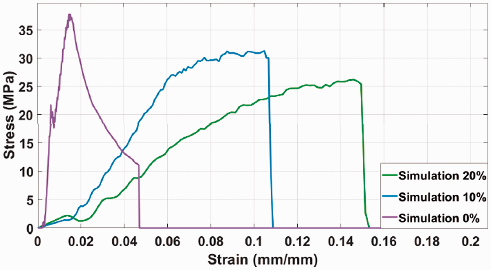
FEM analysis stress-strain curves of compression-out-of-plane simlated tests at various percentages of modified nodes.
In-plane compressive tests along the l and w directions were also simulated with the same parameters and boundary conditions. Results will be illustrated and discussed in “Numerical results” section. In order to validate the numerical model, core samples were manufactured using the fiber orientation analysed through the numerical model (alternating [0,90]s and [90,0]s) and experimentally tested.
Materials and methods
The structure of the CPCC is based on a 2D close-packing pattern of circular cells, that is the geometrical arrangements that allows the largest number of cells per unit area, with walls fabricated using CFRP prepreg layers. The fibre orientations were chosen in order to optimise the mechanical properties along the thickness of the core (90˚) and the length of the layer (0˚) (out-of-plane and in-plane directions, respectively) and to activate the thermal prestresses due to the asymmetry of the thermal properties. Unlike aluminium, CFRP prepreg layers can be co-cured at the joining points between the strips, generating the cells without the need of external adhesives, thus avoiding the generation of discontinuities in the material structure.
The material used is the UD HS200 ER450 epoxy resin pre-preg with HS Carbon T700 24k fibres produced by CIT Composite Materials. The stripes were prepared by layering two plies of prepreg in a [0,90] configuration. The different coefficient of thermal expansions of resin and fibres, coupled with the laminate asymmetry, generates residual thermal stresses when the material is exposed to a strong thermal shock, as previously described. During the manufacturing of the laminates, the air trapped between the two layers of each laminate strip was eliminated with a 15 min vacuum process using an ultrasonic consolidation technique, which improves the removal of interlaminar air and, thus, the mechanical properties of the final part. 71
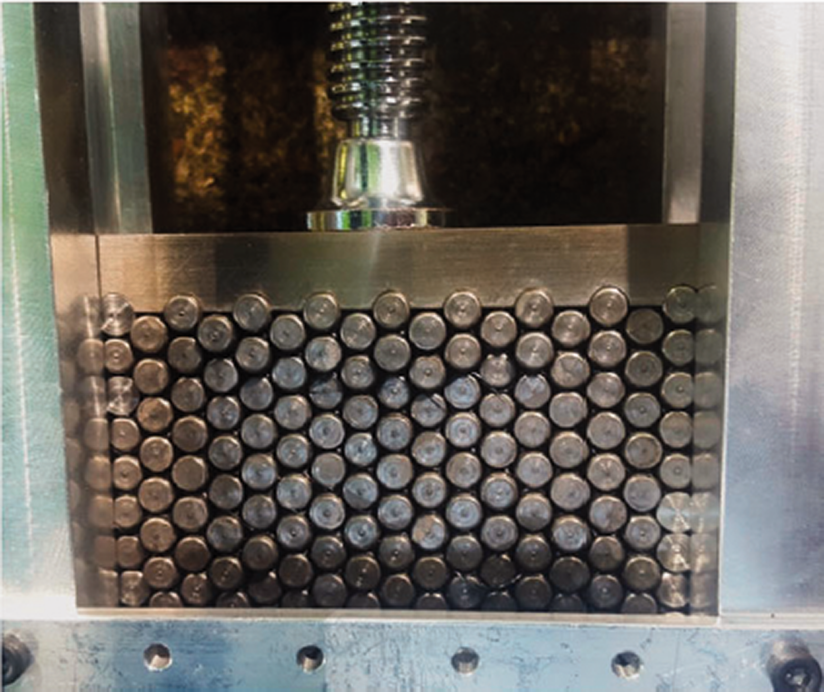
In order to reproduce the circular cell honeycomb structure, a fixture, illustrated in Figure 16, was designed and manufactured, consisting of a double rail system, two bases and up to 30 pins per row with a diameter of 5 mm.
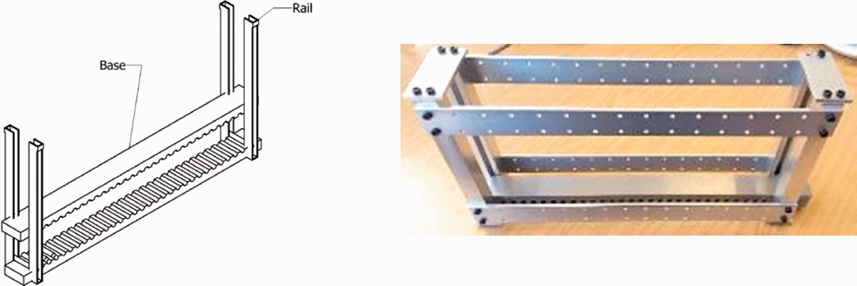
CPCC manufacturing fixture.
A release agent was applied three times on all the surfaces of the fixture in order to guarantee an easy removal of the pins after the cure and avoid damaging the material. The lay-up process starts from a line of pins placed on the lower base (respectively in blue and grey in Figure 17(a)); after this, a first [0,90] CFRP layer is positioned, following the curves of the pins (in purple in Figure 17(b)); another row of pins is then placed on the upper side of the CFRP layer in the concavities between the pins of first row (Figure 17(c)); at this point, another CFRP layer can be placed in the same manner of the first one, but with opposite orientation [90,0], and attached to the first layer in the spaces between the pins, forming the circular cells (Figure 17(d)); the process continues in with the described steps until the desired dimension is obtained and the upper base is positioned. The lateral rails were added in order to limit the horizontal movement of the pins and bases and control the horizontal (l) dimension.
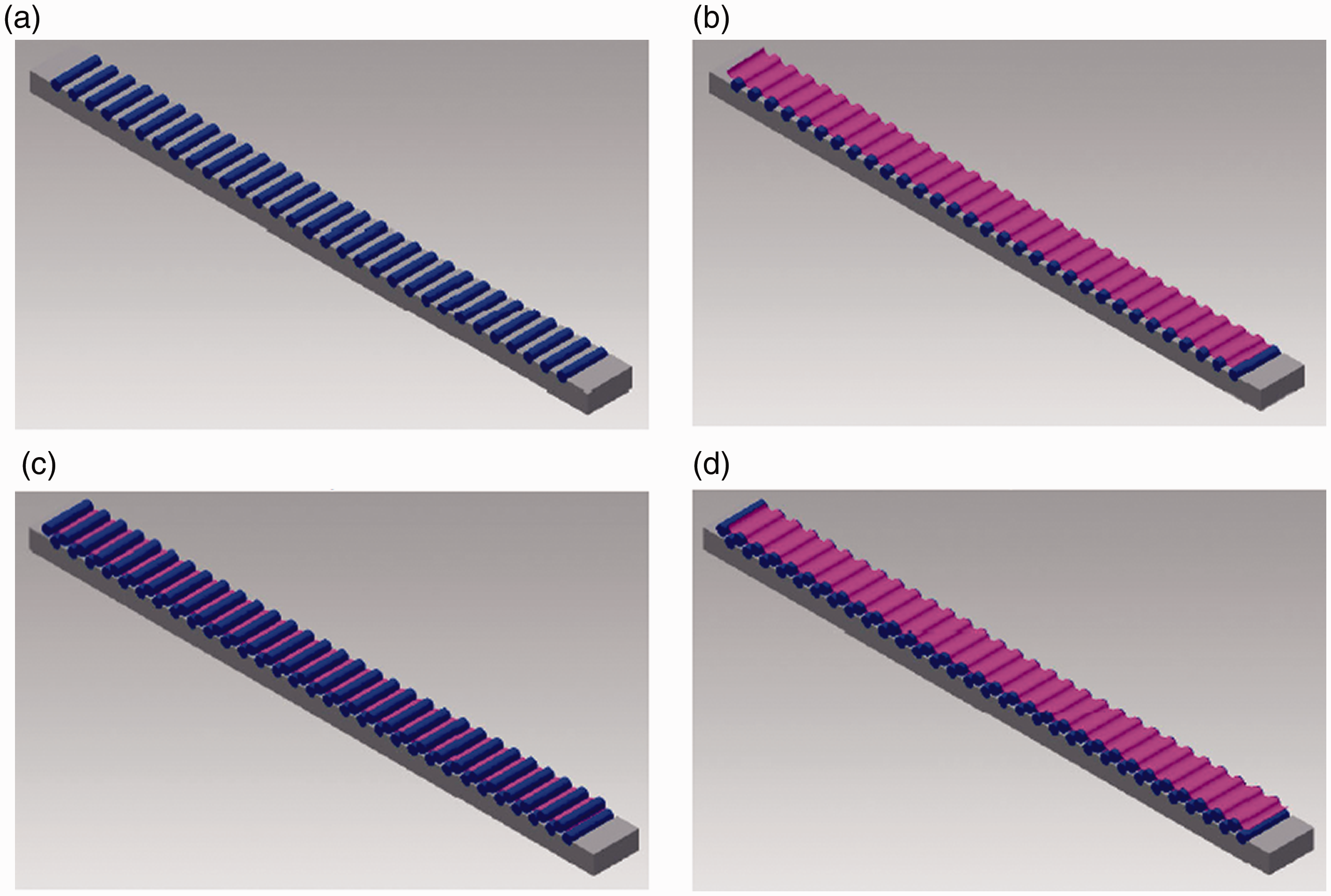
CPCC lay-up steps: (a) the first row of pins (blue) is placed in the base (grey) grooves; (b) the first CFRP layer (purple) is placed on top of the pins; (c) another row of pins is placed on the CFRP layer following the pattern of spaces left from pins of the first row; (d) a second CFRP layer is positioned on the second row of pins.
During the cure cycle, pressure was applied between upper and lower supports in order to consolidate the material while the joints are squeezed between the layers. Figure 18 illustrates a finished lay-up process, with CFRP layers and pins compressed between the two bases. A cure cycle of 2.5 h at 130°C was applied, followed by a water-cooling cycle from 130 to 5°C in around 10 s to insure generation of thermal stresses. A fast cooling is necessary to not allow time for the polymer matrix crystalline structure to adapt and relax the residual stresses. The pins were removed after the cooling cycle, leaving circular empty spaces (cells) in the laminate.
Manufacturing of CPCC samples.
As mentioned above, the [0,90] strips were stacked in an alternate way, so that the side of a strip will face the side with the same fiber orientation in the next strip, creating symmetry at the cells interfaces. A schematic representation of the fibre orientation in the core is shown in Figure 19(a). Following this procedure, the in-plane components of the thermal prestresses in a strip will be oriented in the opposite direction to the ones in the adjacent strip, improving the mechanical response of the core, as previously proved with the FEM analysis. The final product, showed in Figure 19(b), has a cellular dimension of 5 mm and a density of 0.225 g/cm3; this value is in accordance with the analytical predicted value of 0.228 g/cm3.
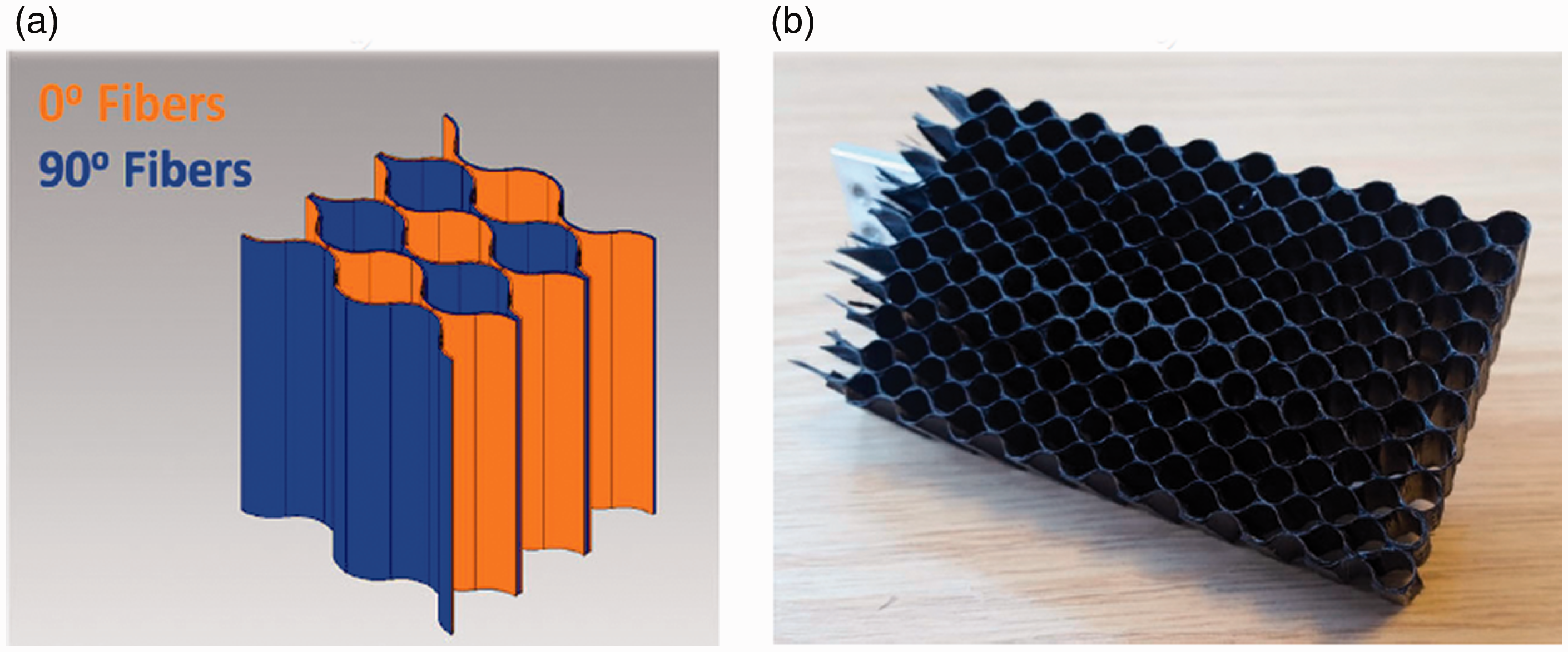
CPCC (a) fibre orientation and (b) final product.
Experimental investigation
As shown by Gibson et al., 1 the contribution of the core in the mechanical behaviour of a sandwich structure mainly depends on its compressive and shear properties. Based on this, an experimental campaign consisting of four mechanical tests (compression out-of-plane, compression in-plane along l and w directions and beam flexure) was carried out in order to determine the compressive and shear properties of the CPCC core.
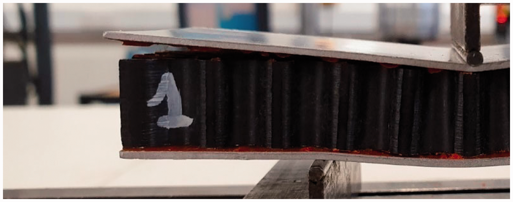
Core samples were tested under flatwise out-of-plane compression load, following the ASTM C 365-03 72 standard. The samples were tested without any support (bare compression test, see Figure 20(a)) and with a cross-head displacement rate of 0.75 mm/min. Following the same standard, flatwise in-plane compression tests (Figure 20(b)) were performed in the two principal planar directions: l, along the long edge of the strips, and w, perpendicular to it. A cross-head displacement rate of 0.5 mm/min was used.
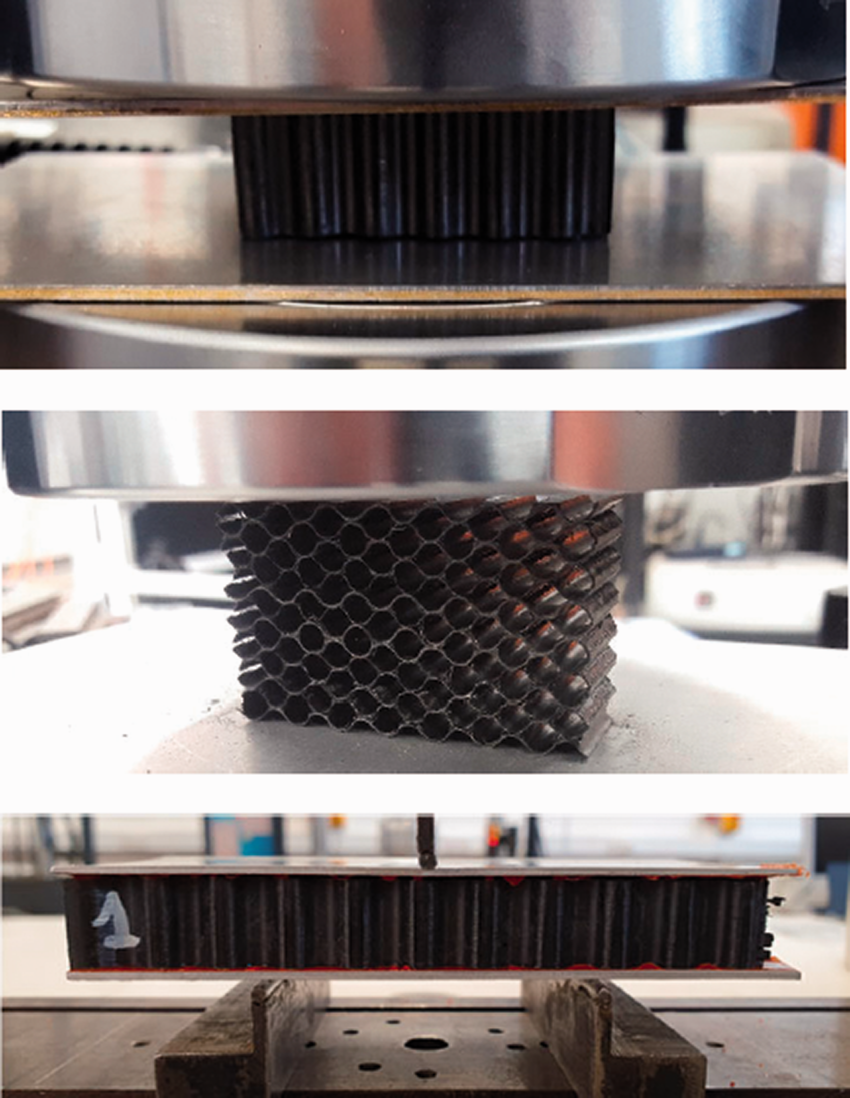
CPCC mechanical tests: (a) compression out-of-plane; (b) compression in-plane (w direction); (c) beam flexure.
Shear properties of the core were evaluated through a beam flexure test, following the standard ASTM C 393-16. 73 The test consists of applying a bending moment to a beam of sandwich structure along the out-of-plane direction. In order to perform the test, sandwich samples were manufactured using CPCC core with 1 mm aluminium skins bonded with 3 M™ adhesive film AF 555 (see Figure 20(c)). Support and loading bars consisting of 25 mm diameter steel cylinders were used, with a displacement rate of 0.2 mm/min, as suggested by the standard.
In order to have a comparison of the mechanical properties with core materials currently in use in advanced engineering applications, the results were compared with those obtained from tests on aluminium honeycomb core. The material used to manufacture the aluminium samples is the HexWeb® CR-PAA Honeycomb provided by Hexcel®. The core consists of expanded aluminium strips with a thickness of 0.076 mm, bonded together by adhesive layers, and has a density of 0.130 g/cm3. Cell-size, wall thickness and density of the two cores are compared in Table 3.
Cores specifications.

Results and discussions
Experimental results
The stress-strain curves resulting from out of plane, l and w in-plane compression and beam flexure tests on CPCC samples (labelled CPCC) are plotted and compared with samples with same dimensions made of traditional aluminium honeycomb (labelled H). The relative properties of the cores are also calculated and compared in terms of percentage variations.
Figure 21 shows the stress-strain curves for the compression out-of-plane test. As can be seen from the curves, the CPCC samples support higher stresses during the test. It is also clear that the area under the CPCC curves is larger than the one under the H curves, as it will be proved by the calculation of the energy absorbed under compression further in this section.
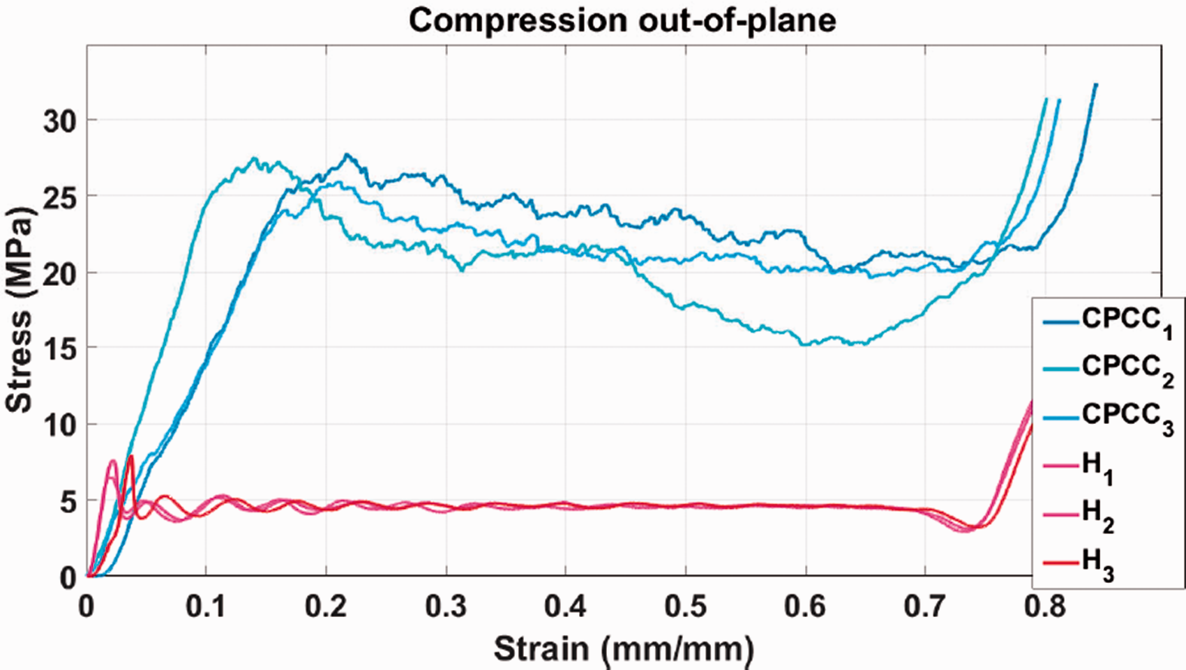
Compression out-of-plane stress-strain curves of CPCC and honeycomb samples.
Figure 22 illustrates a magnification of the elastic part of the stress-strain curves of the CPCC samples. The three samples show at first a higher modulus, but the slope changes for samples 1 and 3 at different values of stress, as highlighted in the image. This change in slope of the linear elastic part has been observed in honeycomb cores by Wilbert et al. 74 and explained as the start point of the elastic buckling of the thin cell walls, which strongly depends on the defects in the structure, explaining the difference between the curves. At the end of the tests, all the samples presented positive peaks at similar values of strain, which is typically due to the densification of the core.
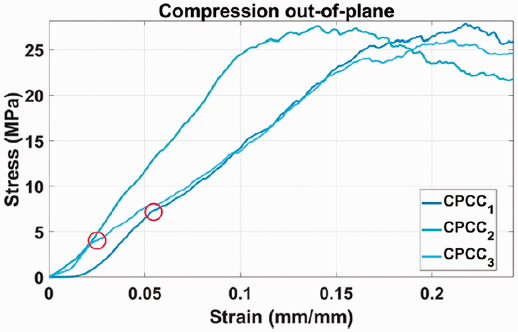
Compression out-of-plane stress-strain curves of CPCC samples: elastic part detail.
Local brittle failures were observed during the test, which lead to the macroscopic pseudoplastic crush of the core, that corresponds to the plateau of the stress-strain curves in Figure 21. As it is possible to note from the comparison with the honeycomb curves, the brittle nature of the CFRP material leads to more oscillations during the compression, but at higher values of stress.
The compression in-plane stress-strain curves are plotted in Figure 23(a) for the l direction and Figure 23(b) for the w direction. CPCC samples supported higher values of loads along the in-plane directions in comparison with honeycomb. Also, it is possible to notice that the CPCC curves showed more oscillations after the linear elastic part. As for the compression out-of-plane, these oscillations may be correlated to the opening of cracks and delamination of the CFRP material that creates numerous local small failures during the crush of the core.
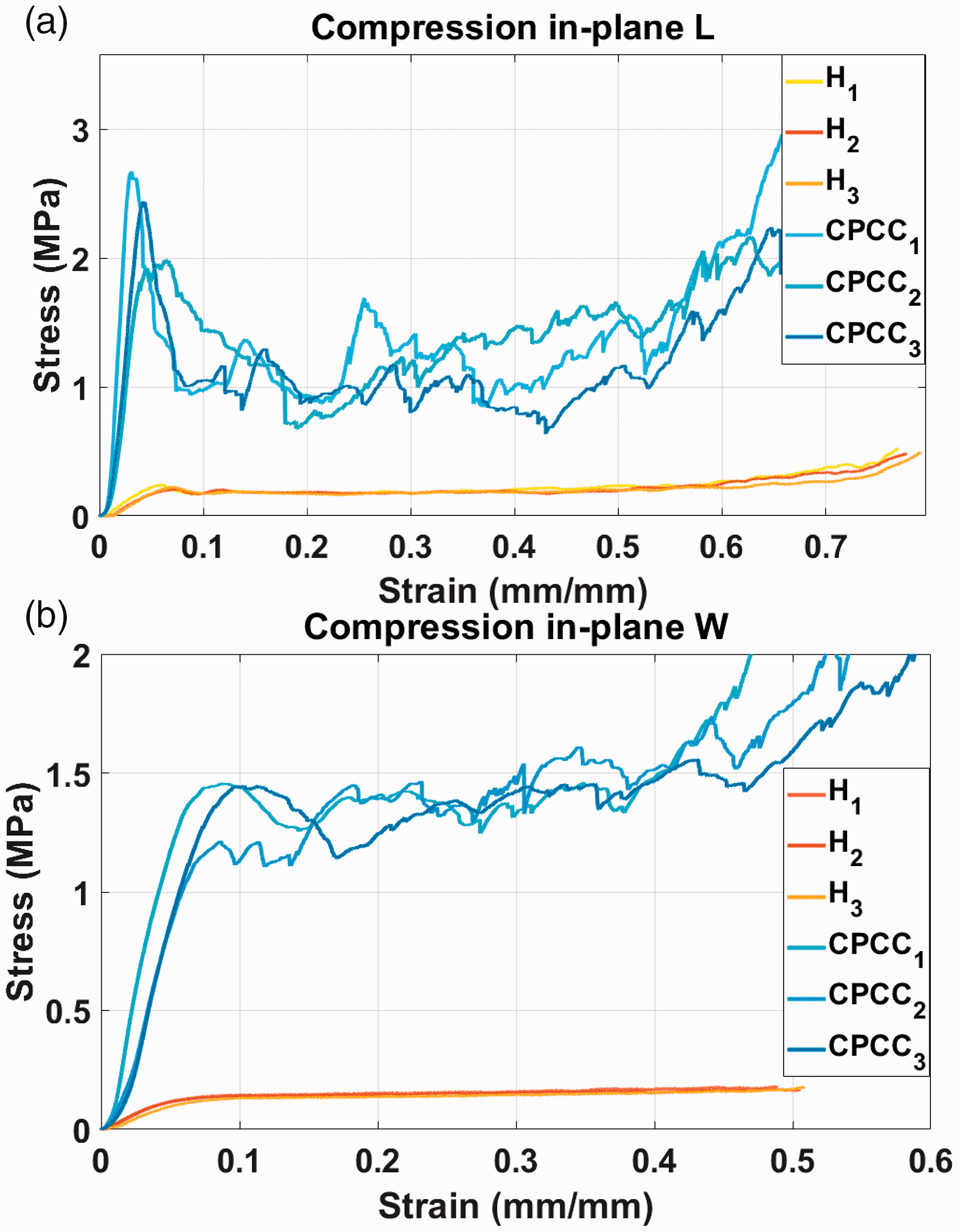
Compression in-plane stress-strain curves along (a) L and (b) W directions.
In Figure 24, the in-plane crush failures of the cores are illustrated for the CPCC (a and b) and aluminium honeycomb (c and d). The failure of the two kinds of core is very similar for the in-plane compression along the l direction (a and c in figure), as predicted in the analytical evaluation of the elastic modulus in “Core design” section: the failure happens for bending of the single walls. The failure along this direction is therefore strongly influenced by the material and thickness of the single cell walls: the CFRP will show higher mechanical properties (modulus and strength) with local brittle failures of the call walls (large oscillations in the plastic part of the curve).
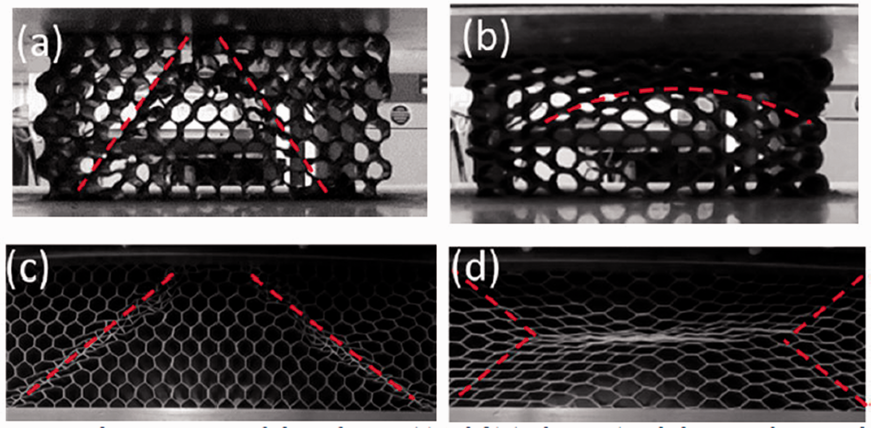
In-plane compressive failure of CPCC (a) (l-direction) and (b) (w-direction) and aluminium honeycomb (c) (l-direction) and (d) (w-direction).
On the other side, the failure for compression along the w direction (b and d in figure) is instead very different between the two cores. For the CPCC, the stress is distributed in an “arch” shape, reflecting the circular shape of the unit-cell along the direction perpendicular to the load, whereas the aluminium honeycomb presents a “X” shape and the cells fold in the middle of the sample. This diversity is mainly due to the different cell geometry and material properties. Indeed, given the “arch” deformed shape, the stress will be carried by the fibers distributed along the circular walls for the CPCC, providing high mechanical properties.
Figure 25 shows the flexural stress-strain curves of the CPCC and aluminium honeycomb samples calculated from the beam flexure tests. The curves are very similar for the two materials and the difference in terms of carried stress is less clear than in the previous tests, but an improvement in terms of modulus and failure stress is still notable. The failure happened at the upper interface between core and skin for all the samples, as shown in Figure 26. This kind of failure is acceptable by the standard and can be used as value of comparison between the two cores since the same kind and dimensions of both the adhesive layers and skins were used. Therefore, a larger value of ultimate stress in this test would mean a better interface strength between the core and the adhesive layer. The adhesive used to manufacture the sandwich samples is an epoxy resin-based material generally used in high performance applications of sandwich structures with honeycomb cores. The higher bonding resistance of the samples with CPCC core can be attributed to two reasons: the chemical compatibility between core and adhesive materials, since they are both based on an epoxy resin matrix, and the higher contact surface given by the larger thickness of the CPCC walls. These two factors led to a stronger sandwich structure capable of carrying higher values of flexural load.
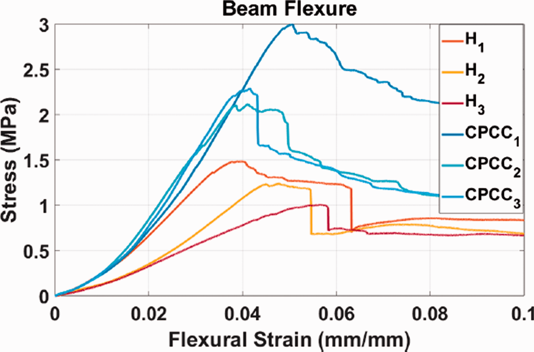
Beam flexure stress-flexural strain curves.
Detail of failure between the core and upper skin during the beam flexure test.
For the compressive tests, modulus and ultimate strength were calculated as follow:
In order to take into consideration, the difference in density between the two cores, the energy absorbed per unit mass of the material, called Specific Energy Absorption (SEA), was calculated using the following equation
Where
The core shear modulus and ultimate strength were calculated as follows
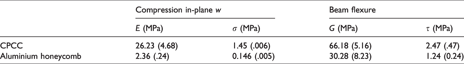
Tables 4 and 5 summarise the results of the mechanical tests performed on the two cores.
Mechanical tests results mean values, standard deviation in brackets: compression out-of-plane and compression in-plane L.
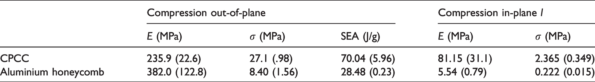
Mechanical tests results mean values, standard deviation in brackets: compression in-plane W and beam flexure.
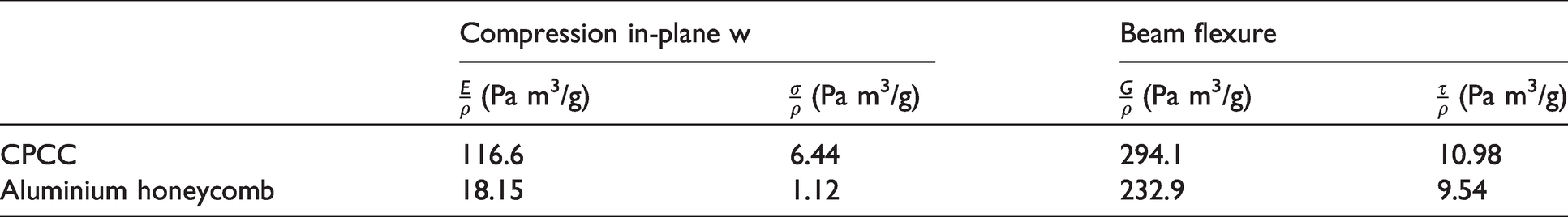
In order to take into account the difference between the densities of the two cores, specific properties were calculated dividing the values by the density of the material. The resulting properties are the specific modulus and specific strength, also known as specific stiffness and strength-to-weight ratio. Specific properties, listed in Tables 6 and 7 allow a reliable comparison between the mechanical properties of the two cores. The comparison is expressed as percentage variation of the CPCC results respect to the aluminium honeycomb ones and summarised in Table 8.
Specific mechanical tests results mean values: compression out-of-plane and compression in-plane L.
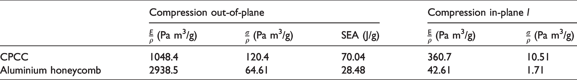
Specific mechanical tests results mean values: compression in-plane W and beam flexure.
Specific mechanical properties percentage variation between aluminium honeycomb and CPCC.
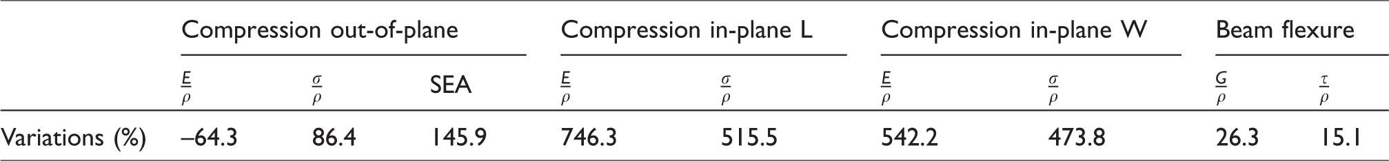
As shown by the percentage variations, there is a clear improvement in almost all the measured specific mechanical properties, with a minimum advantage of +15.1% in shear ultimate strength and a maximum of 746.3% increase in in-plane compressive modulus along L direction. Particularly interesting is also the increment in SEA (+145.9%), that is an important parameter that describes the energy absorbed by the core during the crushing. Furthermore, the higher value of shear ultimate strength leads to a better compatibility of the CPCC core to the adhesive material, increasing the mechanical properties of the sandwich structure.
The only mechanical decrement has been found in the out-of-plane compressive modulus (∼60%). This result was unexpected, because the CFRP compressive modulus in [0,90] configuration should be theoretically equal or higher than the aluminium one when loaded in compression along one of the fibres directions. This mechanical decrement in compressive modulus may be caused by manufacturing defects: strips misalignment, variations of fibres orientation, low pressure applied during the cure, specimens ends not flat, operator errors, etc. These defects can be reduced or eliminated with an automatic manufacturing process. The influence of the defects on the compressive modulus of the core will be numerically proved.
Xiong et al.
31
provided the Ashby’s modified chart for out-of-plane compressive strength vs. density for materials with low density (under 2000
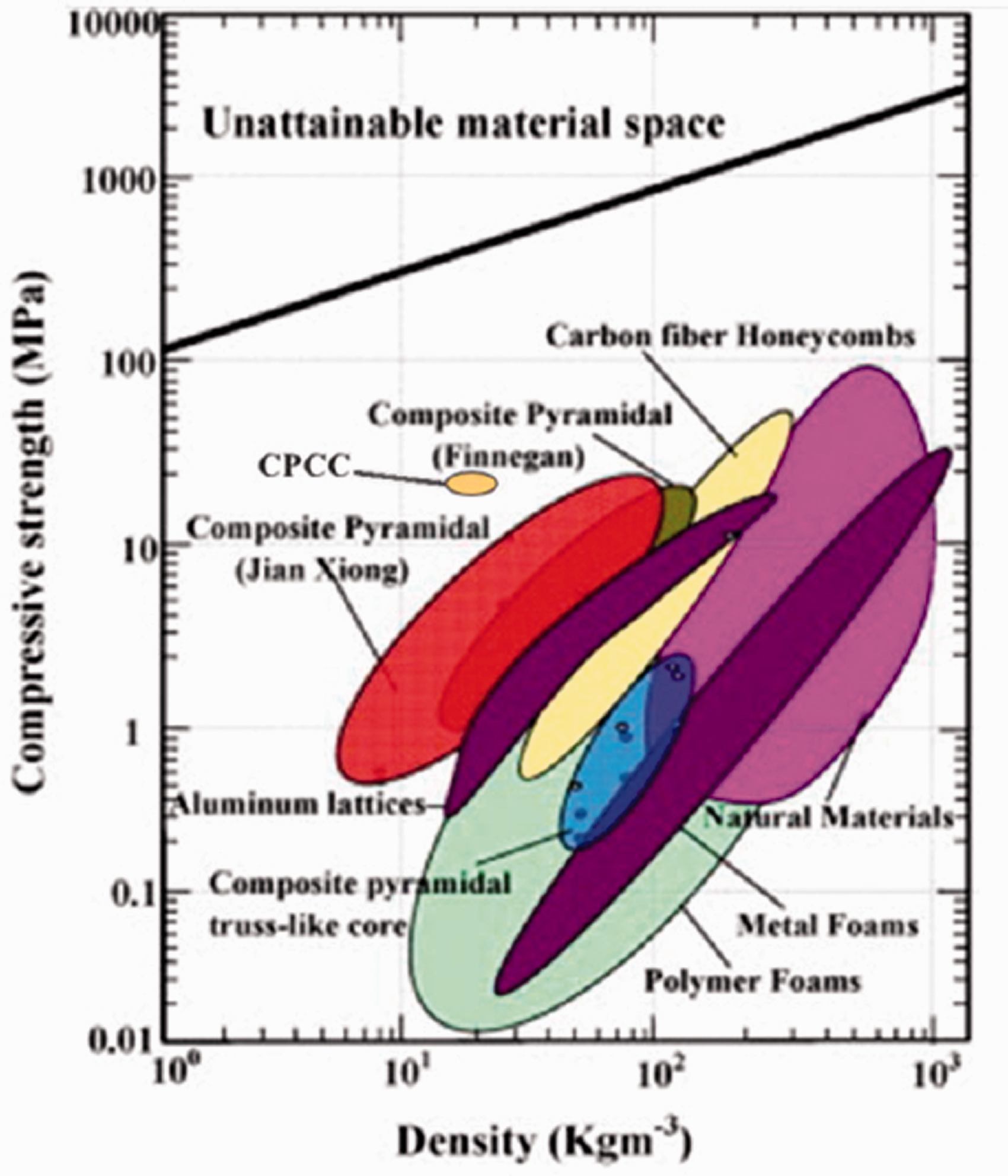
Modified Ashby’s chart for compressive strength vs. density for low density materials. Original figure from Xiong et al. 31
Numerical results
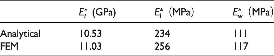
In order to validate the unit-cell numerical model, the Young’s moduli of the cell loaded under out-of-plane and in-plane compression have been calculated and compared to the ones analytically obtained. As it is possible to see in Table 9, the FEM and analytical values match with small variations (under ±10%). In addition, the failure of the samples during the experimental tests along the in-plane directions validates the analytical approximation to hexagonal and elliptical geometries when loaded along the l and w directions, respectively.
Unit-cell elastic moduli: analytical and FEM evaluations.
The results of out-of-plane compression of the experimental and FEM analysis tests of the core samples are compared in Figure 28. A displacement was applied to the defected nodes in the range of ±0.05 mm using the Matlab random function in order to simulate the material defects. The stress strain curves resulting from FEM analysis present sudden drop to zero at the points where the solver is not able to find solution convergence, thus interrupting the calculations, however the FEM curve that matches the experimental data is the one obtained from the 20% modified nodes model. Given that the modulus is decreasing with the percentage of modified nodes, it is possible to confirm that, as previously hypothesized, the low values of
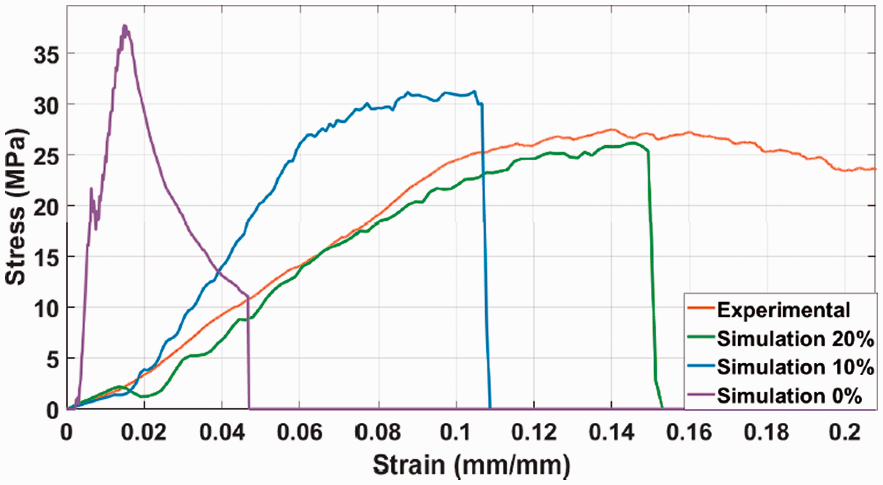
Compression out-of-plane stress-strain curves, comparison between numerical and experimental results.
In-plane compressive tests were simulated using the same FEM parameters and with 20% of damaged nodes. Experimental and numerical analyses results for the in-plane compression tests along w and l directions are compared in Figure 29(a) and (b), respectively.
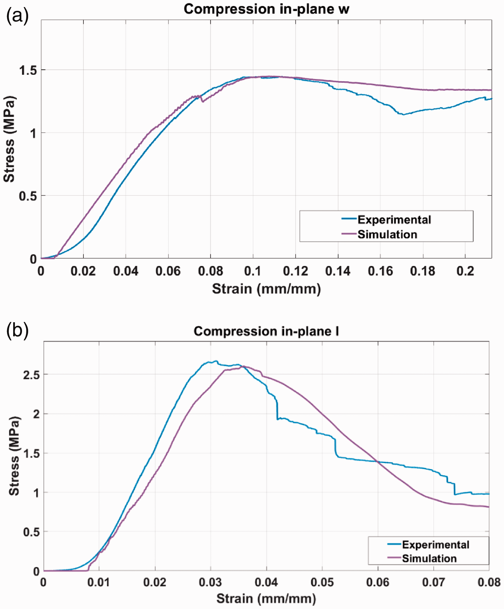
Compression in-plane stress-strain curves in (a) w and (b) l directions, comparison between numerical and experimental results.
The numerical results fit well the experimental curves with a variation in mechanical properties below 10%, proving the validity of the FEM model in the prediction of the mechanical properties of the core.
Conclusions
In this work a CFRP core with bistable circular cell structure, named CPCC, is proposed, manufactured and tested. The structure of the core is a circular honeycomb made with CFRP strips and has a cellular size of 5 mm. Thermal induced pre-stresses were applied to the material during the manufacturing in order to increase the energy absorption capability of the core exploiting the bistable behaviour of the asymmetric laminates. The CPCC was designed with the aim of taking advantage of carbon fibre reinforcement along the out-of-plane and in-plane directions, in order to give high mechanical properties where more needed.
FEM analyses of the cell wall, unit cell and core sample were performed to predict the residual stress distribution generated during the manufacturing of the core. The FEM models were used to study the influence of the fiber configurations on the residual stress and on the crushing behaviour of the unit cell, and to predict the mechanical properties of the core.
CPCC samples were mechanically tested under out-of-plane compression, in-plane compression along two directions and beam flexure and compared with an aluminium honeycomb core. In order to have a consistent comparison with the aluminium core and given the importance of the structural weight in sectors such as aerospace and automotive, specific properties were calculated to take into account the material density. Specific results showed large increments in almost all the characterised mechanical properties in comparison with the aluminium core, with a minimum increment of +15% in specific shear ultimate strength. The highest increments were found to be in in-plane specific compressive properties along both L and W directions, with a maximum of +764% in elastic modulus in L direction.
Numerical results from FEM analysis showed good match with experimental results, thus validating the model. The validated FEM model of the core allows for reduction in future experimental tests and for an optimisation of the core design parameters.
The developed high-performance sandwich core has been proved to provide large improvements in terms of mechanical properties in comparison with the cores currently in use in engineering sectors maintaining a low value of density, and therefore can be employed in high-demanding structural applications.
Footnotes
Declaration of Conflicting Interests
The author(s) declared no potential conflicts of interest with respect to the research, authorship, and/or publication of this article.
Funding
The author(s) received no financial support for the research, authorship, and/or publication of this article.