
Abstract
This paper presents a micromechanics-based 3D finite element model for predicting the damage initiation, propagation, and failure strength of TC33/Epoxy carbon fiber reinforced polymer (CFRP) unidirectional lamina under biaxial loadings. The finite element model is generated by introducing representative volume element (RVE) with a random distribution of fibers and a non-zero thickness, numerically identified interface phase via cohesive elements. In the finite element model, the carbon fibers are considered as elastic, while the elasto-plastic behavior and damage of the matrix are governed by extended Drucker–Prager plastic yielding model and ductile damage criterion. By imposing periodic boundary conditions to the RVEs, various cases subjected to uniaxial and biaxial loading conditions are carried out. During the combined transverse and in-plane shear stress states, a failure transition from compression- or tension-dominated to shear-dominated is captured, and the effects of the interfacial strength on the transition damage mechanisms are discussed. The corresponding failure locus is compared with the upper bound and lower bound predictions of three phenomenological failure criteria (Hashin, Tasi–Wu, and Puck failure criteria) for composites. It was found that in the interface-dominated failure of a CFRP lamina with a weak interface, the Hashin failure criterion performs best among the currently popular failure criteria. However, in the matrix-dominated failure with a strong interface, the Puck failure criterion performs best. Comparing these three criteria, it can be seen the Tsai–Wu may be generally better than both of others as it presents more neutral predictions in both of the examined cases.
Keywords
Introduction
Carbon fiber reinforced polymer (CFRP) composites have been widely used in aerospace and mechanical industries for several decades due to their outstanding specific stiffness and strength. Moreover, the composite laminates with desired modulus and strength in different directions can be achieved by proper design and optimization of an individual lamina. However, in most cases, composite components are usually over-designed considering the safety factors, resulting in the larger and heavier parts. This is mainly due to lack of reliable predictive models and theories to fully understand the mechanical response and failure/damage mechanisms of the composites under various loading conditions. 1 Unlike most homogeneous materials, CFRP composite materials, with heterogeneous nature between different phases, tend to present multiple damage modes depending on the loading conditions, stress states, and possible manufacturing defects. 2 The coexistence of these various damage modes in CFRP composites implies the necessity of the combination of different failure criteria depending on the loading mode. Besides, a failure locus is usually formed by the intersection of various smooth surfaces in the stress space, and each one represents the critical condition for a given fracture. 3 Therefore, it is still challenging to accurately predict failure envelopes of CFRP composites subjected to multi-axial stress states.
Over the last several decades, a large number of failure criteria have been proposed to predict the failure envelopes of the composite materials from limited experimental data, and some of them have been successfully applied to design and calculate the safety factors for the composite structures. They include but not limited to strain-based, 4 strain-energy-based, 5 stress-based,6–9 and phenomenological failure criteria.10–15 Although many failure criteria have been proposed and the modification of some criteria is still ongoing, the validation of these criteria remains challenging. That is due to the inability of these criteria regarding the accurate prediction of the progressive failure process in composites. An objective assessment of the currently available failure criteria for fiber-reinforced composites was conducted under complex 3D stress state to predict the failure strength and to describe the failure envelop in a series of three World Wide Failure Exercises.16–22 The Second World Wide Failure Exercise (WWFE-II), of assessing some existing failure criteria for FRP composite laminates, has shown the satisfactory performance of each criterion to various degrees. However, there still exist considerable variations in the accuracy of the predictions by these criteria. More recently, the third World Wide Failure Exercise (WWFE-III) was conducted to highlight the degree of maturity of 12 internationally recognized approaches (some of them are different from the criteria mentioned in WWFE-II) considering their capabilities of detecting the various damages within the composite materials when subjected to multi-axial loading.20–22 It was found that any two models cannot give identical predictions for any of the 13 test cases. In a few cases, the ratio between the highest and lowest strength predictions can even reach a factor of 20. In addition, the monitoring and visualization of in-situ damage progression during mechanical tests is no doubt challenging and expensive, especially for the multi-axial stress states. Therefore, precise conclusions have not been reached regarding which criterion can best reproduce the physical failure mechanisms and the mechanical strength because of the scarcity of the experimental data, especially under multi-axial stress states. Thus, many criteria have still not been validated for the prediction of the strength of the fiber-reinforced composites. Meanwhile, the input parameters of these aforementioned models were obtained through costly and time-consuming experiments for different material system. However, the results obtained from a given unidirectional (UD) composite material system cannot be extrapolated to other configurations with different fiber volume fraction or constituent properties, leading to a huge amount of investment in their physical characterization. 23
Thanks to the increasing computation power, many of these difficulties can be overcome by taking advantage of computational micromechanics. Computational micromechanics offers a novel approach for a better understanding of the deformation and damage mechanisms by employing the representative volume element (RVE) modeling. Compared to the classic homogenization techniques, computational micromechanics presents two main advantages. On the one hand, this method takes the influences of the geometry and spatial distribution of the three phases into consideration. For example, the size of fiber, the fiber clustering, and the interface connectivity between fiber and matrix are included. On the other hand, the details of the stress and strain distribution under different loading conditions can be captured, leading to more accurate estimation of the onset and progressive process of damage, and the final failure strength. 24 Recently, computational analysis was successfully employed to investigate the mechanical response of the different material systems for the fiber-reinforced composite lamina subjected to the different combined loading conditions, such as transverse tension and out-of-plane shear, 3 transverse compression and out-of-plane shear, 25 transverse compression and in-plane shear,23,26 transverse tension and in-plane shear, 23 and transverse compression and axial tension. 27 Interface modeling is a crucial part of RVE modeling with the finite element method (FEM), and usually, a cohesive crack model is implemented to simulate the mechanical response of the interface between the fiber and matrix. In the linear behavior before the onset of damage, an initial stiffness Ki (105 GPa/mm) is used in most research26–32 to simulate the elastic behavior of the RVE model. The choice of this parameter is based on that it should be large enough to ensure the displacement continuity at the interface and to avoid any modification of the stress fields around the fiber before damage. 26 However, it was found that the average Young’s modulus and the strength of the interphase are around five and nine times larger than those of the bulk resin matrix. 32 Therefore, the interphase was modeled as a separate zone with the same constitutive and damage models of matrix, which makes the model more complicated. The parameter identification of the interphase of the carbon fiber reinforced composite was conducted by the inverse strategy based on the experimental data, microstructural modeling method, and Kriging metamodel, including the identification of thickness, normal stiffness, and tangent stiffness. 33 This set of parameters was applied to predict the elastic and strength properties of carbon FRP composite yarn, and good agreement was found with other regular simulation models. 34 In order to obtain accurate results from FE simulations, the constitutive model used for the matrix material modeling plays an important role. There are several constitutive models proposed for modeling matrix behavior, namely Mohr–Coulomb model (M–C), Drucker–Prager model (D–P), and a new model proposed by Melro et al., 35 which are widely used to conduct failure analysis of composite materials within the framework of micromechanics, see Canal et al., 3 Gonźalez and LLorca, 24 Totry et al., 26 Melro et al., 29 Tan et al., 31 and Sun et al. 32
In this paper, a micromechanics-based FE model employing RVE modeling is developed for the investigation of the failure/damage mechanisms and assessment of the failure envelopes of UD CFRP composites subjected to transverse and in-plane shear stress states. A novel approach for generating random fiber distributions is applied using the discrete element method (DEM) with high volume fractions and any specified inter-fiber distances. 36 Five RVE models with different random fiber distributions and the same volume fraction are built for the investigation of the effects of the different fiber distributions on the mechanical response of the composite. The linear extended D–P model and the ductile damage model are adopted in the modeling of plastic behavior and damage of the matrix, the damage mode transition, and associated change of stress-based yielding law in the D–P model are discussed. In addition, the cohesive crack model is adopted for simulating the mechanical behavior of the interface with the identified elastic parameters from Lu et al. and Zhu et al.33,34 The predictions with upper and lower bounds from three popular failure criteria are compared with the numerical results in terms of a weak and a strong interface for the evaluation of these criteria under different transverse and in-plane shear stress states.
Computational micromechanics modeling
Computational micromechanics modeling is performed on the RVEs of the UD CFRP subjected to homogeneous stress states, such as tension, compression, and shear. A total number of around 50 fibers is enough to capture adequately the essential features of the microstructure of the material
24
while maintaining reasonable computing efforts. In addition, the average radius value and average volume fraction are obtained experimentally to be 3.115 μm and 65.12% in Zhu et al.,
34
respectively. The microstructure of each RVE is idealized as the dispersion of 50 circular fibers with an average radius of 3.2 μm randomly embedded in the matrix, making a volume fraction of 65%. The size of RVEs is chosen to be 50 μm × 50 μm × 6 μm, considering the insignificant effects of depth on the transverse properties. The novel approach for generating the 2D random fiber distribution to overcome the jamming limit is adopted from the previous study,
36
and extruded along the fiber direction to achieve the final RVE configuration of the UD composite material. FEM models are generated in ABAQUS/Explicit to overcome the convergence difficulty of numerical analysis. The fibers and matrix are meshed using six-node linear triangular prism elements (C3D6) with hourglass control, and the interface is meshed with eight-node cohesive elements (COH3D8). Typically, around 52,000 elements are adopted in each RVE to capture the large stress gradients between neighboring fibers; see Figure 1 for an illustration of the RVE model with random fiber distribution. In order to accelerate the simulation process, mass scaling is normally utilized in the ABAQUS/Explicit to artificially increase the mass of elements, resulting in an increase of the time increment. However, this technique can influence the results largely, especially during an analysis of dynamic study where the inertia effects become dominant. A common way to check the influences of the mass scaling on the numerical results is to compare the kinetic energy with the internal energy, and a ratio below 10% can be regarded as an insignificant effect.37,38 Therefore, the stable time increment for the mass scaling is selected as 6 × 3D RVE FE model with random fiber distribution and its microstructure distribution.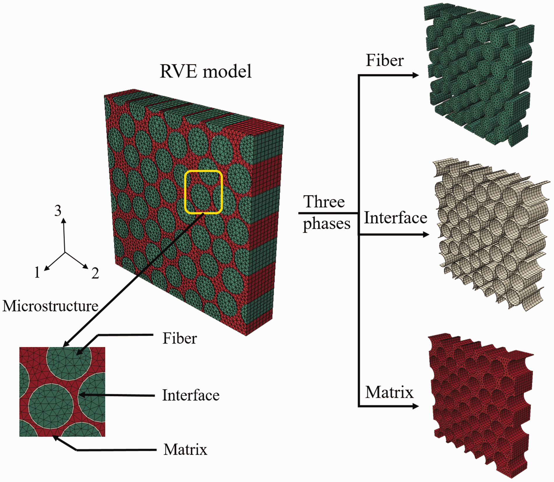
The response of the UD composite subjected to various loading conditions can be obtained from the homogenized stress σij and the homogenized strain

Constitutive laws of fiber and matrix


After the yielding process of the polymeric material, an additional criterion is needed for the prediction of the onset of damage. Experimental findings
43
show that the polymer exhibits a rather brittle fracture behavior under the uniaxial tension while a large plastic deformation under uniaxial compression and pure shear. This behavior can be governed by the ductile criterion, which assumes that the equivalent plastic strain at the onset of damage 
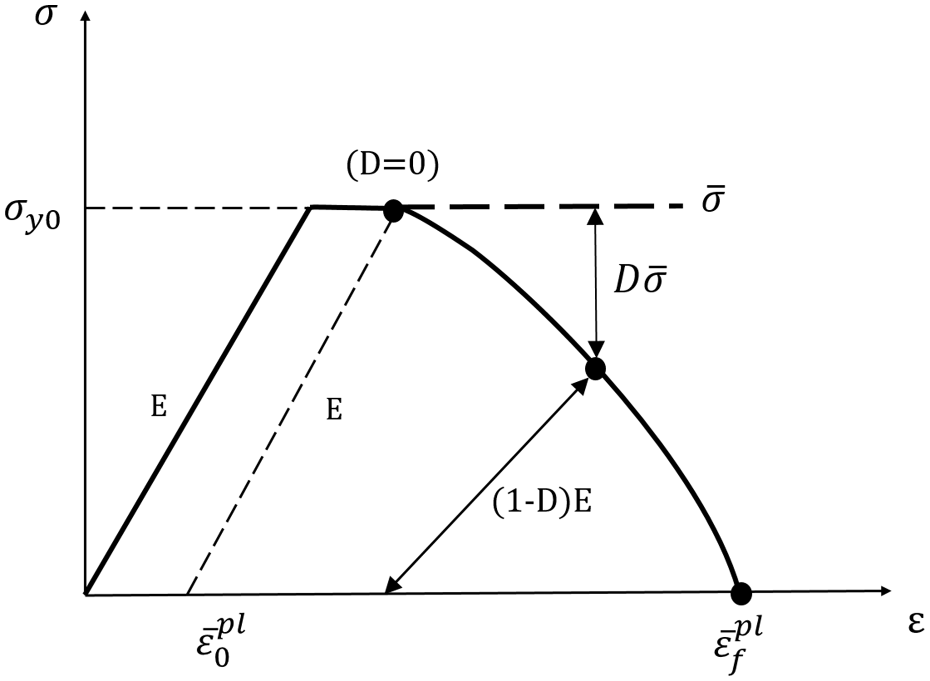
Once the ductile damage initiation criterion is met, the following damage propagation is controlled by a damage evolution law, and the whole process from elastic behavior until final failure is illustrated in Figure 2. The solid curve represents the damaged stress–strain response, which manifests in two different forms: softening of the bold yielding stress and degradation of the elasticity, while the dashed curve is the material response in the absence of damage. When material damage occurs, the stress–strain relationship can no longer represent the material behavior accurately. That is because the stress–strain relationship can introduce a strong mesh dependency based on strain localization, in which the energy dissipation decreases with a finer mesh. Therefore, the softening response after damage initiation is characterized by a stress-displacement response rather than a stress–strain response to alleviate mesh dependency of the results. This can be achieved in the FE model by introducing the critical fracture energy, defined as the energy required to open a unit area of crack, and a characteristic length L. The fracture energy can be expressed as
Stress–strain curve of the polymeric matrix with progressive damage.
The characteristic length is calculated based on the element geometry. For 3D geometry, the length is equal to the cube root of the integration point volume for solid elements. The initial plastic strain for the onset of damage is chosen as 0.05 for tension and 0.5 for compression and shear considering their experimental mechanical performances.
44
Cohesive element model of interface
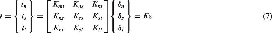
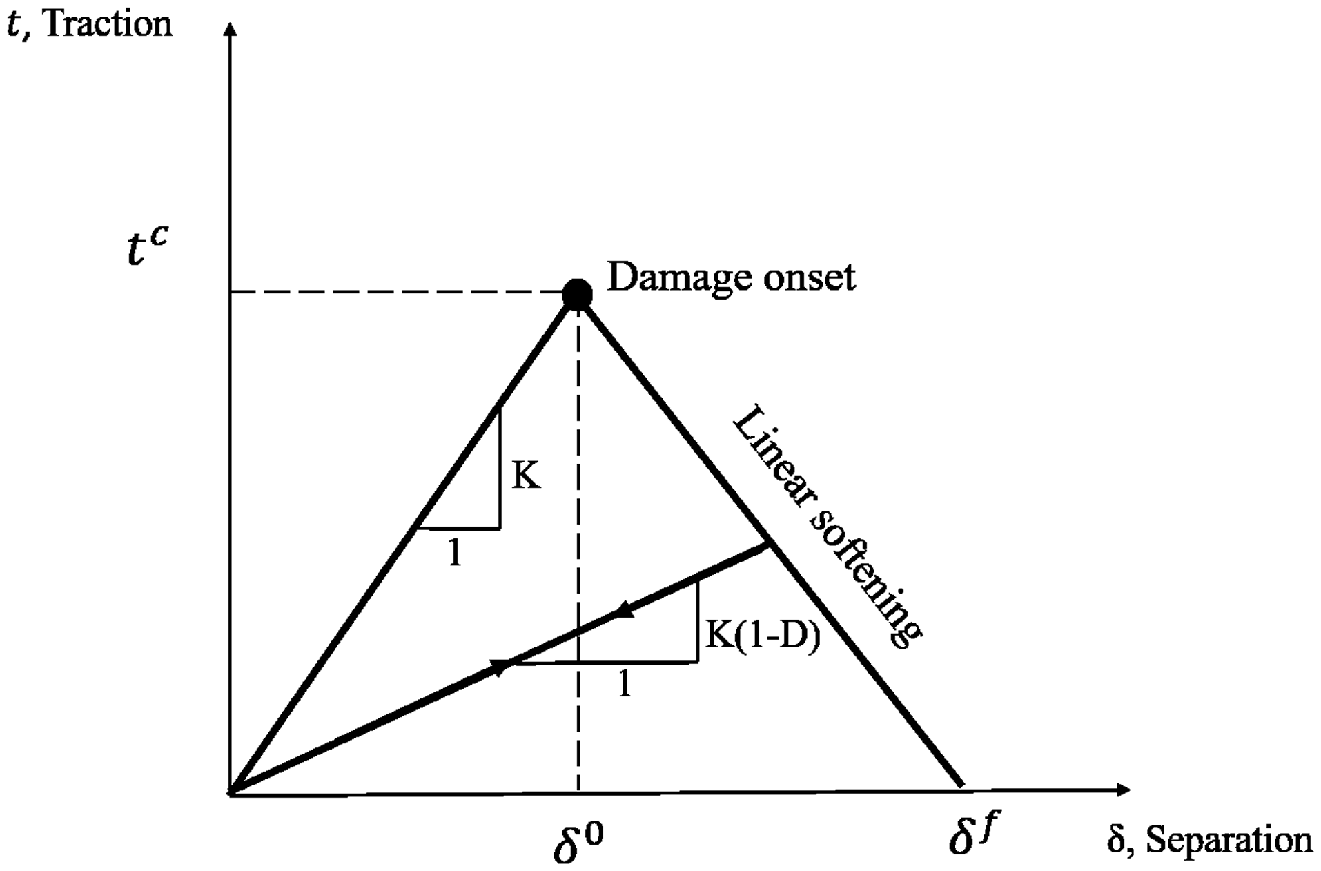
The fiber–matrix interface is modeled using cohesive element, which is controlled by the bilinear traction-separation law. The elastic behavior is written in terms of an elastic constitutive matrix that relates the nominal stresses to the nominal strains across the interface. The nominal traction stress vector 
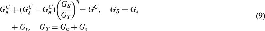
Damage is initiated when a quadratic interaction function involving the nominal stress ratios reaches a value of one. This criterion can be represented as
Traction-separation law of the interface.
Periodic boundary conditions
PBC is imposed on the corresponding surfaces of the RVE by means of introducing the equations between the periodic nodes, in order to guarantee the periodicity of the displacement and traction fields as well as to ensure the continuity between the neighboring RVEs. The unified PBCs are expressed in terms of the displacement vectors 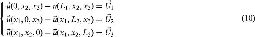
Assessment of the mechanical response of the RVE under uniaxial loading conditions
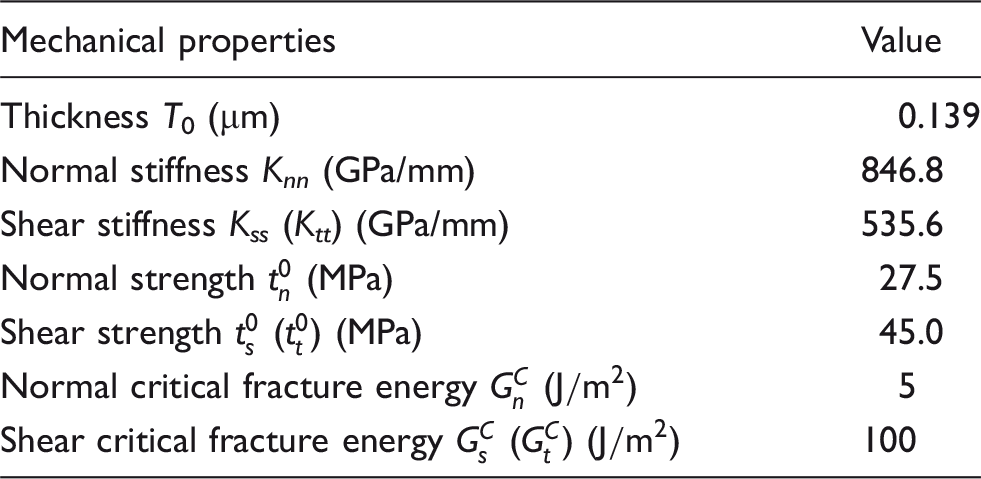
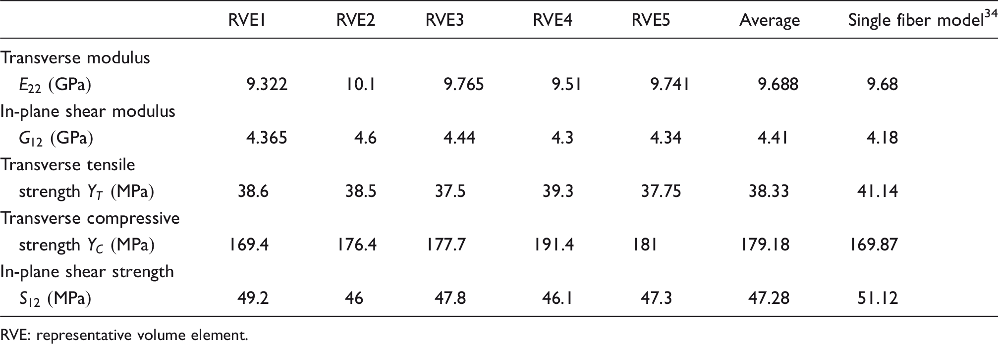
Before the prediction of the damage mode and envelop of the UD RVE under biaxial stress states is conducted, an assessment of the RVE model, with a reasonable fine mesh, appropriate boundary condition and material properties, is required. In order to retain the accuracy of the numerical results with a reasonable computational cost, five RVE models with different fiber distributions are generated with around 52,000 elements, and the primary results are summarized in Table 3. It is worth noting that the transverse modulus was obtained by averaging Young’s modulus from transverse tension and compression cases, and the average value is almost identical with the value obtained from the idealized single fiber model.
34
All of the predicted properties are in good agreement with the single fiber model within a difference of 7%. The details of the stress–strain curve and ductile damage distribution of RVE1 can be found in Figure 4, where all the simulations were practically superposed in the elastic regime, divergences arose at the onset of matrix plastic deformation and interface debonding, then increased/decreased when the composite strength reached its plateau.
Predicted stress–strain curve of five RVE models with different fiber distributions (left) and predicted damage variable contour of RVE1 (right) under different uniaxial loading conditions: (a) transverse tension; (b) transverse compression; (c) in-plane shear. Comparison of predicted elastic and plastic properties of five random RVE models with the idealized single fiber model.
34
RVE: representative volume element.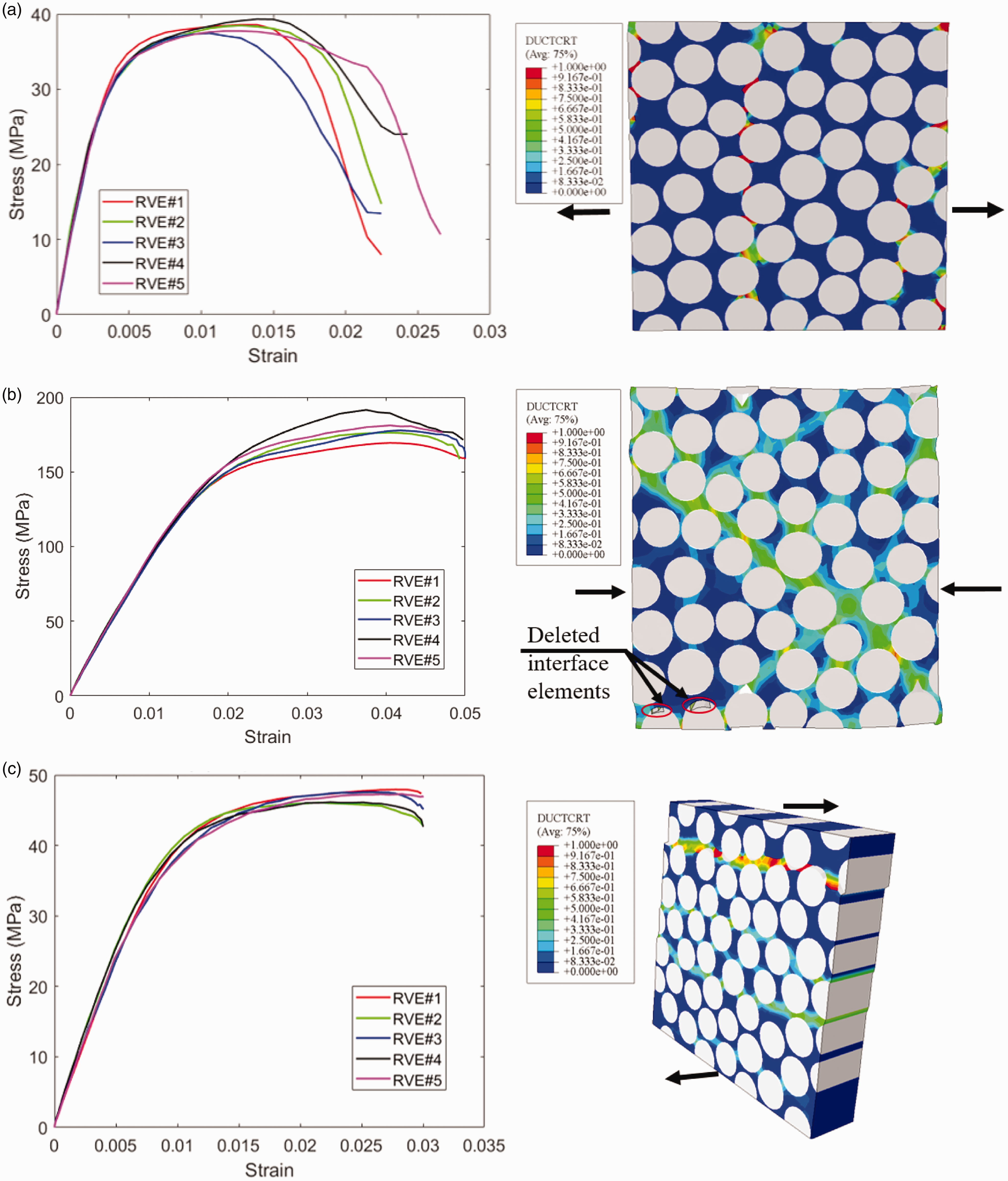
During the pure transverse tension loading condition, the damage process is mainly dominated by the interface debonding. Non-linearity of normal stress appeared in the stress–strain curve when it meets the interface strength, which is shown in Figure 4(a) (left) and the mechanism of deformation and damage in tension is observed in Figure 4(a) (right), which shows the contour plot of the ductile damage distribution in matrix. The crack always starts at the interface close to fiber cluster, where the fibers are more closer to each other, resulting in the stress concentration in these regions. The damage in the interface initiates firstly by the nucleation of interface cracks, responsible for the non-linearity behavior at small strains, and grows along the interfaces. After damage initiates from the interface, the matrix experiences severe plastic deformation due to the stress concentrations at the interface crack tip. Then the damage propagates along the weakest path at the relatively matrix poor region determined by the spatial distribution of interface cracks, perpendicular to the loading direction. Final failure occurs by linking up the interface cracks through the RVE.
During the pure transverse compression, the damage initiates from the interface in the form of debonding, then the matrix bears the load afterward. After the damage initiation, matrix plastic damage starts to develop at the vicinity of the debonding positions, and the curves in Figure 4(b) (left) become stable, which indicate that the compressive strength is dominated by the matrix. Finally, the matrix cracks at different locations are linked together to form the main shear band passing through the interface cracks with an orientation of 52° relative to the loading direction, which is very close to the published findings24,44 and is shown in Figure 4(b) (right). All of the five simulations under transverse compression are superposed in the elastic regime and started to diverge at the onset of the matrix plastic deformation. The largest strength among the five RVE models is found in RVE4, which is probably due to boundary effects and the rotation of the fiber as one fiber was divided into a same part at four corners of the RVE model.
During the pure in-plane shear loading, the damage of the UD composite lamina is dominated by interfacial decohesion or by matrix yielding, depending on the interface strength. 46 Here in this study, the interface strength is smaller than the matrix shear limit, thus, the crack initiates from the interface in a form of interfacial debonding and then the matrix holds the shear loads in the most time. Therefore, the damage starts from the interface and propagates as a result of the interactions between the interfacial debonding and the matrix plastic deformation by linking them together. Several different damage surfaces, passing through the RVE perpendicular to the loading condition, can be found in the RVE at different locations, which is shown in Figure 4(c) (right).
FEM prediction of the damage initiation and propagation and failure strength under transverse and in-plane shear loadings
Once the validation of the RVE model is completed, it could be used to predict damage modes and failure envelop of the UD composite materials subjected to biaxial loading conditions. The topics about the transition damage modes between transverse and in-plane shear stresses, and the failure loci for the whole range of this combined stress state are covered. The scheme of the combined transverse tension/compression and in-plane shear stress state is depicted in Figure 5. Two different loading paths can be applied to the RVE for the combined stress state: the first is to apply a transverse load up to a prescribed stress state and then a shear load is applied until the final failure while the total transverse load acting on the RVE is held constant; the second is to apply the transverse and shear displacement simultaneously to the RVE by a proportional amount, which is designated as radial loading path. It is worth noting that no significant influence of the loading path on the failure loci was found from the biaxial experimental results47,48 and the combined transverse compression and shear numerical simulations.47,49 Therefore, here in this study, the radial loading path was applied to the RVE for the combined transverse tension/compression and in-plane shear stress states.
Schematic of the RVE of UD composite subjected to combined in-plane shear and transverse stresses.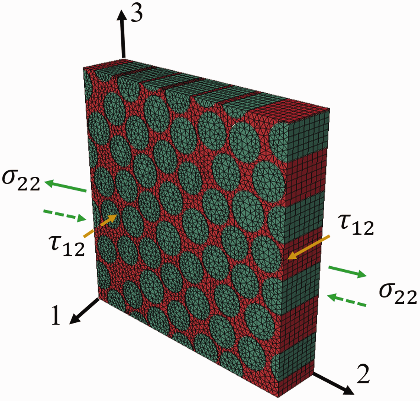
Transition of the damage mechanism
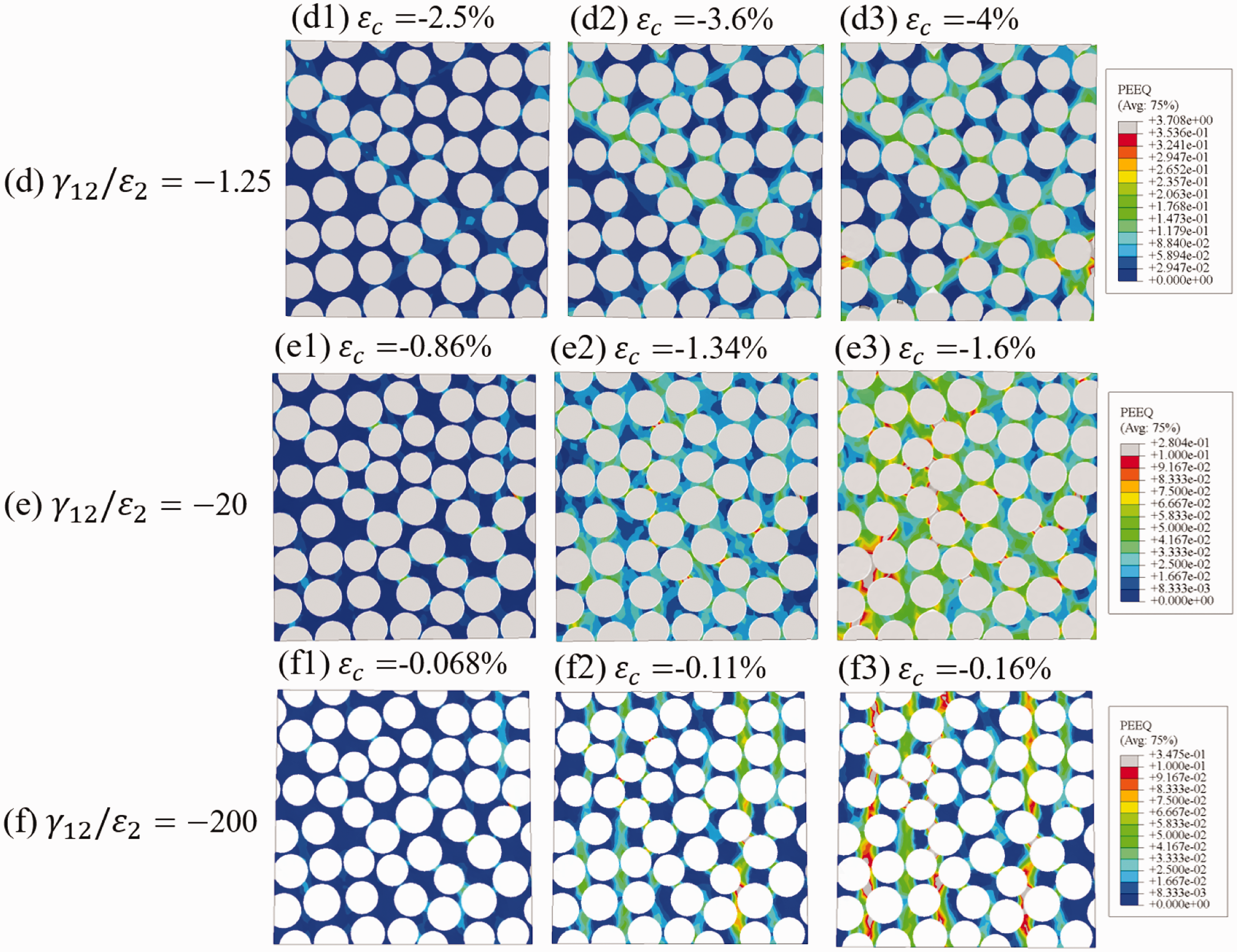
One of the most interesting phenomena in the investigation of progressive damage of composite lamina under transverse and in-plane shear is the finding of transverse point. Two different damage modes exist at the same time around the transition point, and only one damage mode can be observed when it is far away from the transition point. Here in this study, six different loading cases were selected to reveal the transition modes and transition of damage mechanisms. The mechanical behavior of the composite lamina under different loading paths characterized by Mechanical response of the composite lamina subjected to transverse and in-plane shear loadings in the Contour plot of the accumulated plastic strain in the composites subjected to biaxial transverse tension and in-plane shear: (a) Contour plot of the accumulated plastic strain in the composites subjected to biaxial transverse compression and in-plane shear: (a) 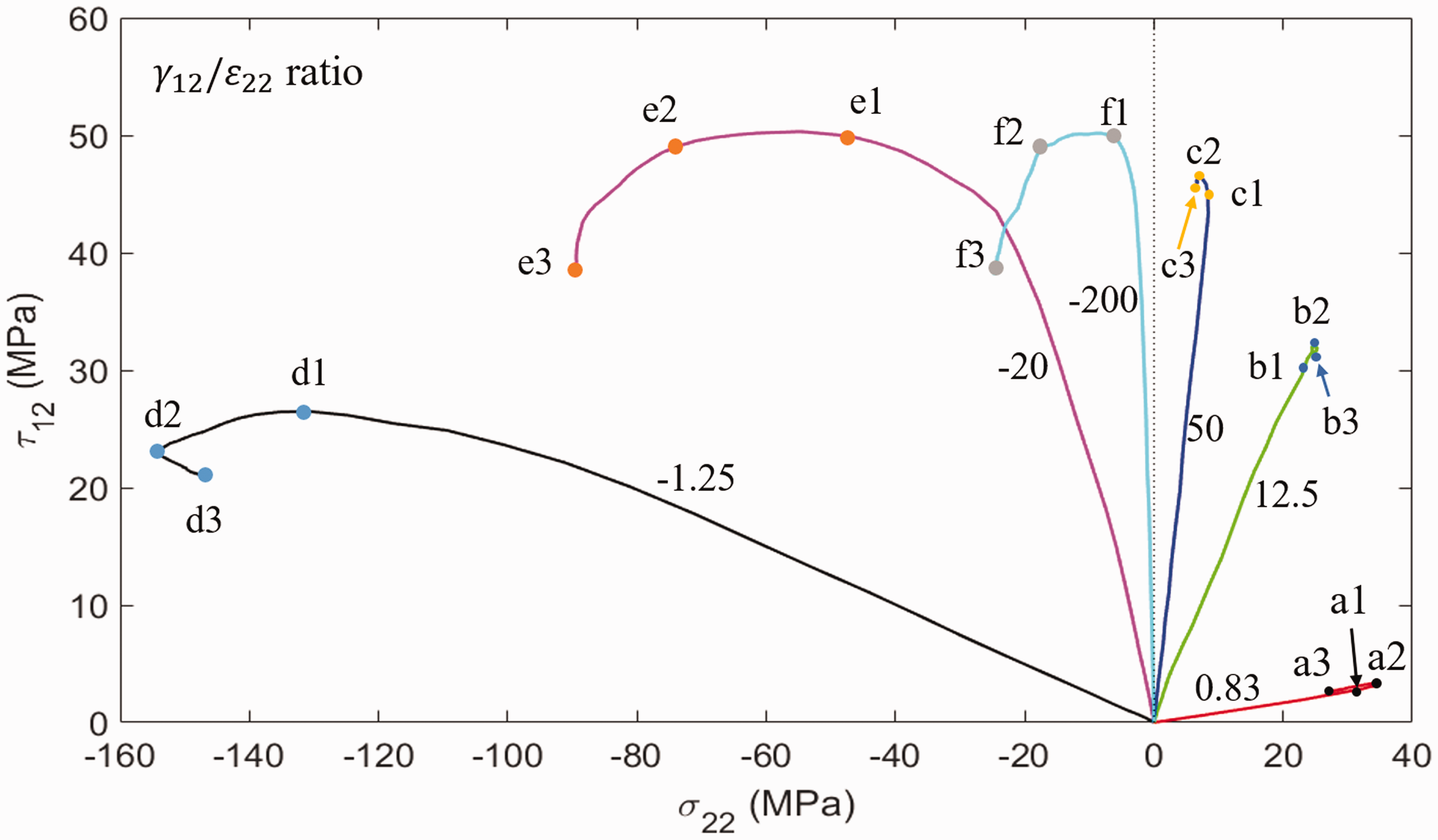
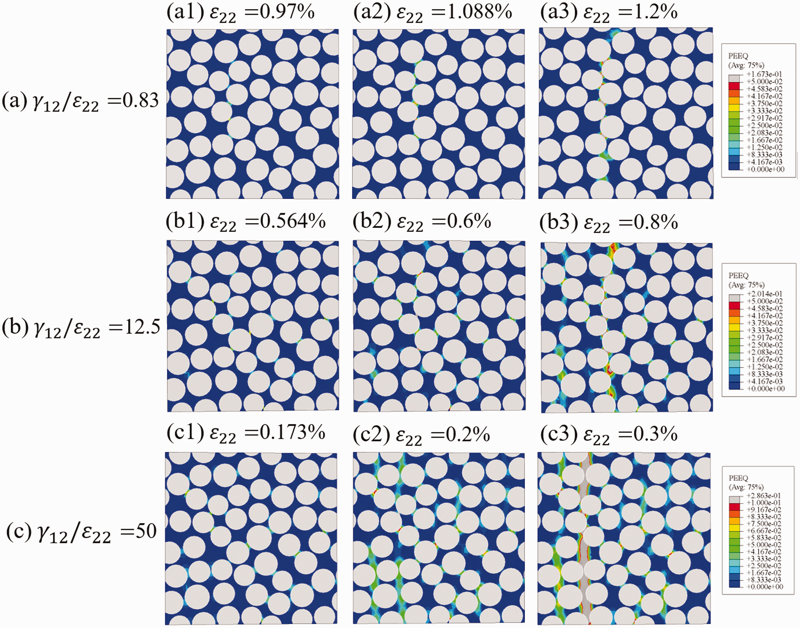
Transition of the damage mechanism under transverse tension and in-plane shear loadings
At the low ratio (
Transition of the damage mechanism under transverse compression and in-plane shear loadings
For the transverse compression and in-plane shear cases, the simulation results from the lower ratio (
Comparison between the classical failure criteria and numerical results with a weak interface
Currently, there exist a large number of failure criteria which are mostly stress-based, including fully interactive criteria such as Tsai and Wu10 and damage mode based criteria like Hashin 12 and Puck and Schürmann.13,50 The Tsai and Wu10 criterion predicts failure with a highly integrated equation involving all stress components by combining different damage mechanisms. Different from the Tsai and Wu criterion, the Hashin criterion is capable of distinguishing the fiber and matrix damage initiation in composite materials, and either one is further subdivided into two damage mechanisms such as tensile and compressive modes. Despite the capability of this criterion for predicting the damage in the lamina under uniaxial loading, numerous studies showed that it does not always agree with the experiments accurately, especially under the combined transverse compression and in-plane shear. This disadvantage is due to neglecting the shear hardening effects with the presence of transverse compression. 14 Hashin’s criterion has been further developed by Puck and Schürmann13,50 by addressing matrix compression failure with a model based on Mohr–Coulomb hypothesis, which assumes that damage is triggered due to the normal stress and tangential stress, acting on the fracture plane with a specific inclination angle to the material plane.
The predictions of those models are based on the mechanical tests, which should provide the lamina strength under transverse tension YT, transverse compression YC, and in-plane shear S12. As there was no experimental result available, these magnitudes were obtained from the computational micromechanics simulations,
34
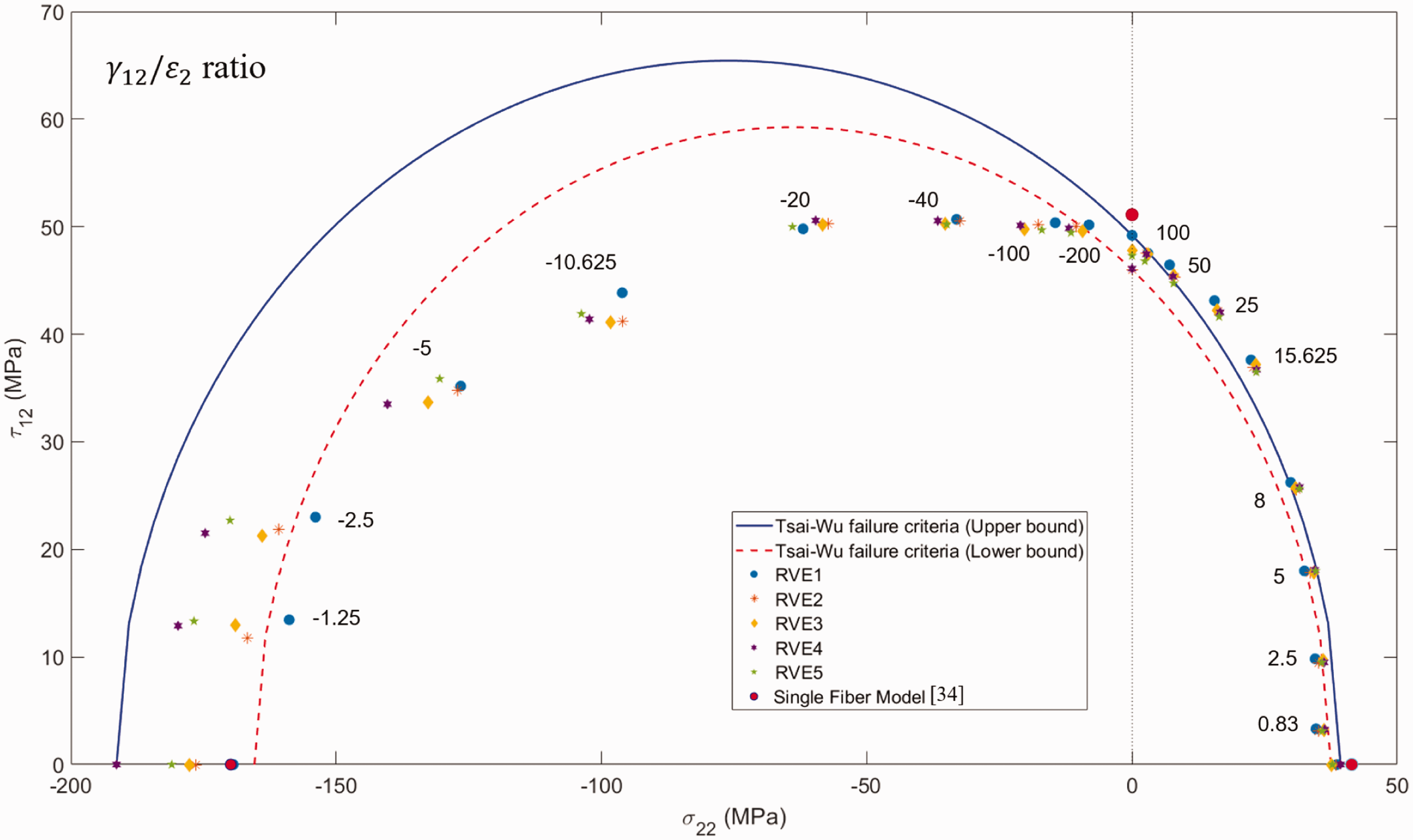
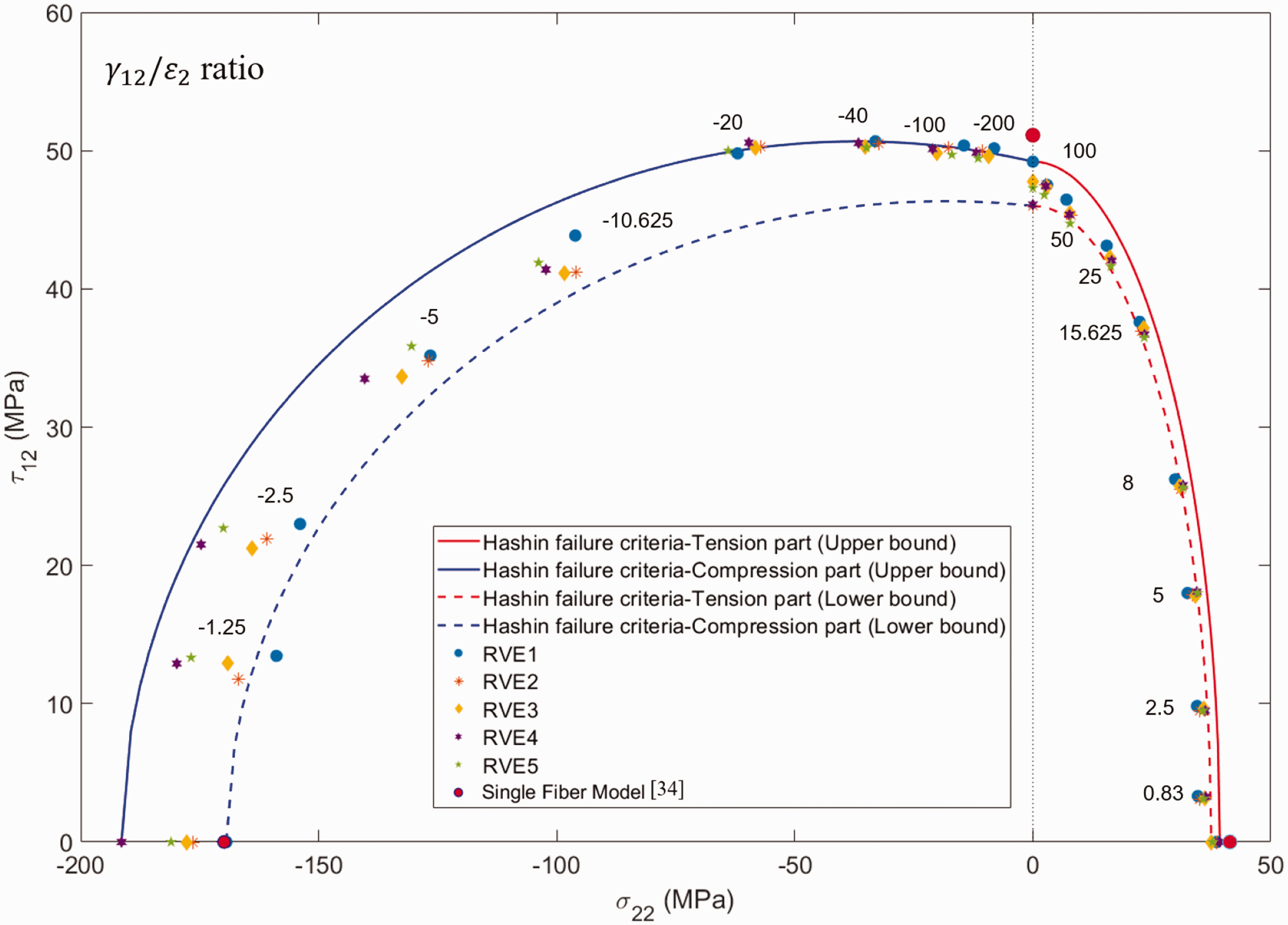
which is presented in Table 3. The failure envelopes under transverse loads and in-plane shear ( Comparison of the predicted failure surface and Puck, Hashin, and Tsai–Wu failure criteria subjected to transverse load and in-plane shear. The numbers next to points represent the ratio of shear strain (γ12) to transverse strain (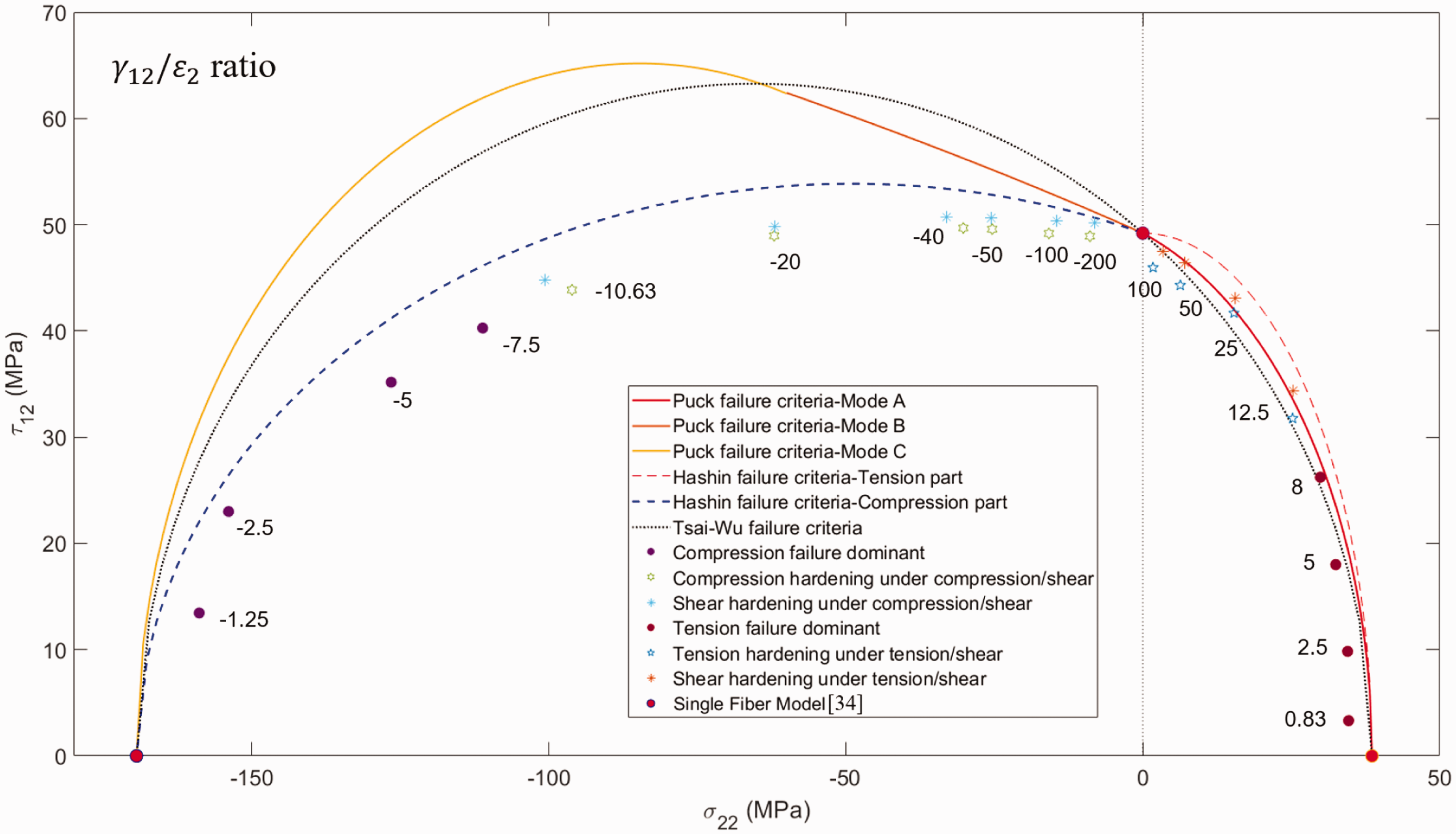
For
Once the transition point subjected to the biaxial loading was found, an appropriate yielding behavior of the matrix described by the Drucker–Prager should be chosen after the point. The lowest and highest strengths of the lamina under different uniaxial loadings from Table 3 were selected as the lower bound and upper bound to plot the failure envelopes from the Puck, Tasi–Wu, and Hashin criteria. These envelopes were compared to the numerical simulations obtained from the five RVE models under biaxial loadings, which can be found in Figures 10 to 12. It was found that during the tensile dominant failure period when Comparison of numerical simulations of UD composite and failure envelopes predicted by Puck criterion under combined transverse and in-plane shear stress states. The numbers next to points represent the ratio of shear strain (γ12) to transverse strain ( Comparison of numerical simulations of UD composite and failure envelopes predicted by Tasi–Wu criterion under combined transverse and in-plane shear stress states. The numbers next to points represent the ratio of shear strain (γ12) to transverse strain ( Comparison of numerical simulations of UD composite and failure envelopes predicted by Hashin criterion under combined transverse and in-plane shear stress states. The numbers next to points represent the ratio of shear strain (γ12) to transverse strain (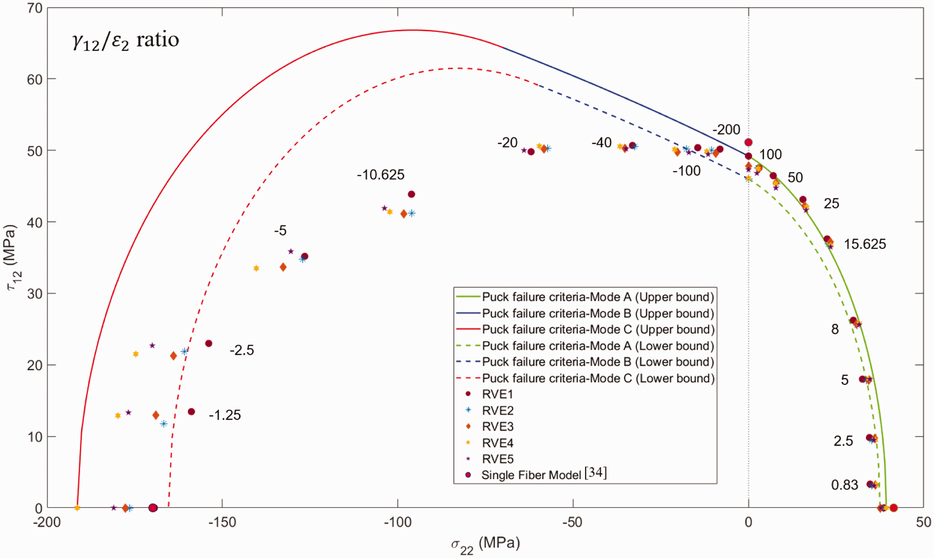
Comparison between the classical failure criteria and numerical results with a strong interface
As the interface strength can influence the damage modes of UD composite largely subjected to biaxial stress states, it is worth conducting another set of simulations with a strong interface subjected to the same biaxial stress states. The influences of the interface strength was investigated in Canal et al. and Totry et al.3,26 in the form of a weak and a strong interface subjected to different loading conditions. It was found that damage of composites is controlled by the matrix with a strong interface, and controlled by the interface with a weak interface under transverse compression and longitudinal shear, 26 as well as transverse tension and out-of-plane shear. 3 Here in this study, six different biaxial loading cases, covering the transition point from compression-dominated failure to shear-dominated shear, were conducted on the five RVE models with different fiber distributions, and 112 MPa was chosen as the interface shear strength to represent a good fiber/matrix bonding. 26
The comparison of numerical results and different failure criteria is shown in Figure 13, where the lower and upper bounds for plotting the failure envelopes come from the minimum and maximum strength values of five RVE models under uniaxial loadings. It is worth noting that the numerical simulations can explain the transition from shear failure to compressive failure with different damage modes. The shear failure is characterized by a linear increases of the shear strength until the transition point Comparison of numerical results and failure envelopes of UD composite predicted by (a) Puck, (b) Tasi–Wu, and (c) Hashin subjected to combined transverse compressive and in-plane shear stress states. The numbers next to points represent the ratio of shear strain (γ12) to transverse compression strain (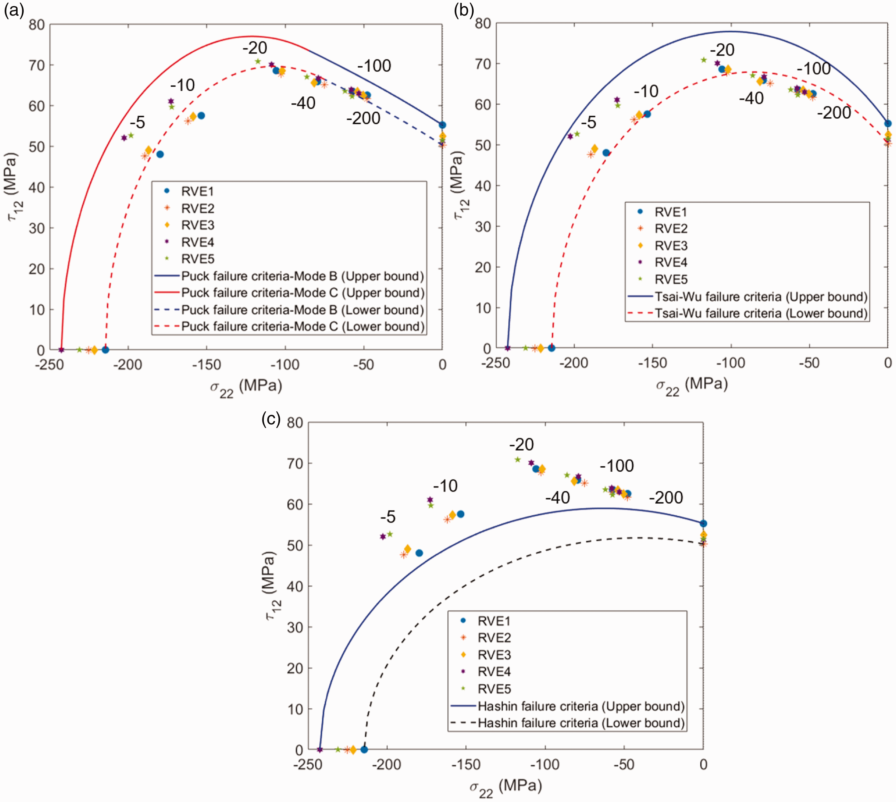
Conclusions
In this study, a comprehensive set of RVE based on computational micromechanics is developed in commercial FEM software ABAQUS/Explicit to investigate the failure/damage mechanisms and failure envelopes of UD TC33 carbon fiber UD composite lamina subjected to biaxial stress states. Random fiber distributions are generated from 2D DEM models and the RVEs are obtained in forms of three phases including identified interface properties. Taking the statistic into account, five RVEs are adopted for each case. The transition from compression or tension to shear-dominant damage and the orientation of the fracture plane are adequately predicted by the FE simulations, and the key findings are shown as below:
The transition from compression-dominated failure to shear-dominated failure arises when shear strain is larger than 20 times the absolute compressive strain. Thus, during the shear-dominated failure cases, the hardening of matrix should be switched to shear in the D–P model in ABAQUS/Explicit. This also applies to the transition from tension to shear when shear strain is larger than 12.5 times the tension strain. During the combined transverse tension and in-plane shear loading conditions, the failure of composites with a weak interface is controlled by nucleation and growth of interface tensile cracks in the tension-dominated damage mode. However, when it is beyond the transition point, the failure is controlled by the interface shear cracks in the shear-dominated damage mode. During the transverse compression and in-plane shear loading conditions, the damage is controlled by the nucleation of the interface crack and propagates by the formation of shear band in the matrix under compression-dominated failure. However, when it is beyond the transition point and enters into the shear-dominated failure, the damage is controlled by the interface shear fracture. The effects of the interface strength on the mechanical response of the composite lamina are investigated, and the upper bound and lower bound predictions of the failure criteria are introduced to eliminate their dependence on the uniaxial strength data. The results clearly revealed that the Hashin failure criterion provides a better estimation for the failure locus of the UD lamina subjected to transverse and in-plane shear loadings, when the mechanical behavior of the composite with a weak interface is controlled by the interface decohesion. However, when it comes to matrix-dominated failure cases where the interface strength is larger than the matrix shear strength, the Puck failure criterion can provide a better estimation for the failure locus under the same biaxial loading conditions. It is hard to say which one is better because in a specific situation, depending on the interface properties, different failure criterion has its own strengths and drawbacks. Comparing these three criteria, it can be seen the Tsai–Wu may be generally better than both of others as it presents more neutral predictions in both of the examined cases. This could be due to the fact that Tsai–Wu criterion is a generalized stress-based criterion but this does not in any way suggest that Tsai–Wu criterion is always more accurate for other cases.
The FE modeling is useful for validation of current composites failure criteria, especially for those loading conditions where experiments are extremely difficult to conduct. These results showed the potential of computational micromechanics simulations to assist the modification of existing failure criteria and the development of new failure criteria for composites in general. With the help of our current models, the complex loading conditions such as combined longitudinal and shear stress states and triaxial loading conditions will be considered. It is important to note that the friction condition between the fiber and matrix is not considered in these cases, which is the next topic in our future work.
Footnotes
Declaration of Conflicting Interests
The author(s) declared no potential conflicts of interest with respect to the research, authorship, and/or publication of this article.
Funding
The author(s) disclosed receipt of the following financial support for the research, authorship, and/or publication of this article: Lei Wan would like to thank China Scholarship Council (CSC) and the School of Civil Engineering at University of Leeds for their financial support for his PhD studies.