
Abstract
Today the impregnation of dry fibre materials is a production method preferred for large composite parts like wind turbine rotor blades or aircraft wing covers. One of the recurring problems of the production process is that the used resin distribution channels leave marks on the surface of the part. The result of the marks in the channel area is a localized deformation of the fibre material, and hence the laminate becomes more prone to shear buckling in this area. The purpose of this paper is to present a report on an unconventional infusion method to avoid channel marks on composite part's surfaces. The channels can be activated by a pressure difference. If the channels are deactivated during a specific process window no channel marks will be left on the part's surface. In order to verify the inexistence of channel marks, three analytical processes are used.
Introduction
Increasing cost pressure in the wind power and aerospace industry makes it necessary to establish more cost-effective manufacturing processes for the sometimes very large fibre composite components. The economical infiltration of a liquid resin system into an unsaturated fibre material presupposes a strategy which, on the one hand, achieves the required laminate quality and on the other hand reduces the consumption of auxiliary materials and resin. Frequently, in the case of the conventional infusion methods a flow media is used which has a high permeability to increase the flow path and the flow rate. An advantage of this flow media is that the partly very large fibre composite components are additionally impregnated in the laminate thickness direction. 1 However, additional resin is also needed, which must be removed from the component after the infusion with the flow media. Thus, the additional resin is necessary only for the infusion process, but does not contribute to the finished component from a mechanical viewpoint. The following sample calculation underlines this statement. For a 35 m2 carbon fibre-reinforced plastic wing cover, an amount of 170 kg is needed. The resin absorption of a normal flow media is about 500 g/m2. That means 10% (17.5 kg) of the total resin quantity remains in the flow media. Depending on the resin, this additional resin is not only a cost factor but also production waste.
Another possibility to impregnate dry fibres and to avoid long flow paths is the use of multiple of resin distribution channels. However, these channels must be positioned on the component surface. 2 Due to the process, the channels leave marks on the component surface, which lead to fibre undulations. These undulations cause local disturbances in the laminate, which can lead to a premature failure of the component. This applies in particular to areas in which a compressive stress of the laminate occurs and leads to the failure form of shear buckling.
In the vacuum differential pressure infusion, reusable resin distribution channels are used which have no direct contact with the infusion resin. The objective of the development is to place channels for the infusion directly on the component without leaving any serious imprints on the cured part.
State-of-the-art infusion processes
In order for the resin to flow from the resin reservoir into the vacuum bag (cavity), there must be a pressure difference between the resin reservoir and the cavity. This is the basis of all infusion methods. A difference is made between infusion and injection in mould design. Rigid mould halves are required for resin transfer moulding to withstand the injection pressure above atmospheric pressure. In the infusion process, on the other hand, one half of the mould can be replaced by a flexible film because the resin pressure is below atmospheric pressure. This is achieved by evacuating the cavity. 3
The pressure difference created by sealing the cavity with a vacuum bag film and evacuating it causes a change in the thickness of the preform. As soon as the resin is pressed into the cavity, the pressure in the cavity increases to the pressure of the resin. The pressure distribution depends on the flow front, and due to the lower pressure difference to the ambient pressure, the fibre material is decompressed. This increases the thickness of the fibre material again (see Figure 1).
The pressure and relaxation behaviour of fibre materials differs. A cyclic loading and unloading process continuously reduces the thickness of the preform. The pressure behaviour of impregnated fibre materials compared to dry fibre materials deviates because the resin provides a different friction coefficient between the individual layers. For impregnated fibre materials, therefore, a lower pressure is required to achieve an equivalent thickness to dry fibre materials.4–6
Overview of infusion processes
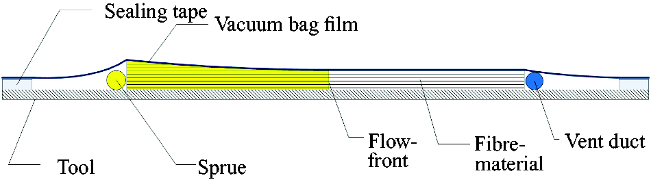
In the well known infusion method, vacuum-assisted resin transfer moulding (VARTM), the fibre material is placed on the prepared mould. This can be done either layer by layer or in preformed layer packages (preforms). This structure is covered with a peel ply and air sealed by a vacuum bag film and sealing tape. The peel ply ensures that the vacuum bag film and the resin channels can be separated from the part after infusion and cure of the resin. 7
In order to be able to control the flow front, several sprue channels can be positioned on the component surface depending on the component and based on empirical values or flow simulations. The possible flow paths of the resin and the confluence of the resin fronts are decisive for the arrangement of the channels. 8
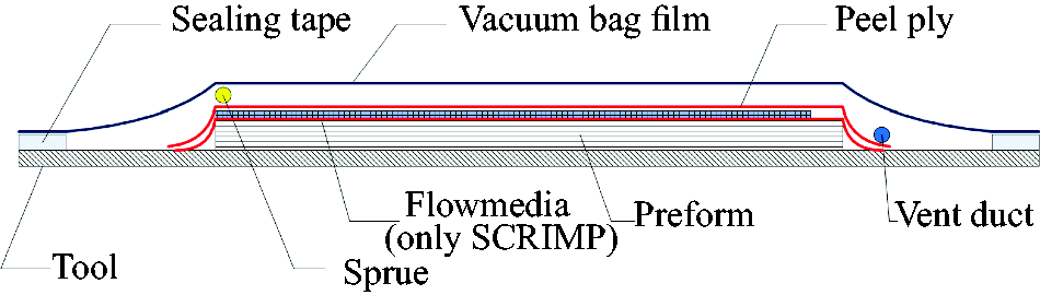
For a rapid distribution of the resin, the VARTM process has been modified. The so-called Seemann Composite Resin Infusion Moulding Process (SCRIMP) uses, as shown in the Figure 2, a flow medium for resin distribution. The flow medium is a woven or knitted fabric with a low flow resistance and distributes the resin over the component surface. This additionally impregnates the dry fibre material in the thickness direction.9,10
Schematic drawing of VARTM/SCRIMP process.
23
The vacuum-assisted process (VAP) uses a flow medium similar to the SCRIMP process. In addition, a semi-permeable membrane is used, which covers the entire component and is sealed at the edges. A vacuum bag film, which is separated from the membrane by a breather, creates a second cavity above the component. This second cavity is evacuated during the entire infusion process. Since the membrane is only gas permeable, but impermeable to resins, the volatile components and gases can be removed from the component, and voids are avoided. The confluence of flow fronts is not critical in this process, and therefore, no additional vent ports have to be provided, which are the last to be reached by the flow front in other infusion processes.11,12
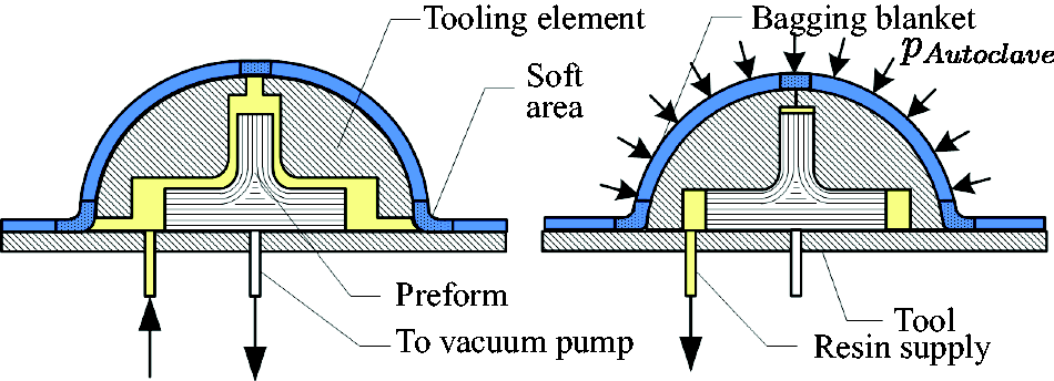
An autoclave is used for the production of wing covers for the Airbus A220 (formerly Bombardier Cseries). The patent for the resin transfer infusion (RTI) process, published in 1998, shows that a bagging blanket with stiffened and soft areas is used (see Figure 3). The resin pressure, which is higher than the ambient pressure for the infusion, interacts with the bagging blanket to create flow channels. The pressure in the autoclave is increased after complete impregnation so that the excess resin flows off again from the resin-rich areas created in this way. The excess resin is displaced, and the fibre volume content is adjusted.
13
In 2003, the Boeing Corporation patented an infusion process to improve the fibre volume content and thickness distribution. In this controlled atmospheric pressure resin infusion (CAPRI) process, the fibre material is compressed by cyclic loading and unloading prior to infusion. For this purpose, the cavity is cyclically evacuated and pressurized. During the infusion not only the cavity is evacuated, but also the resin reservoir, and thus, the pressure gradient is reduced. The lower pressure gradient leads to a reduction of the laminate thickness gradient, but the infusion time can also be extended.14,15
In the vacuum-induced preform relaxation (VIPR) process, the permeability of the fibre material is affected. For this purpose, an attachable vacuum chamber is positioned on the vacuum bag film as shown in the Figure 4. By evacuating the vacuum chamber to a lower pressure than in the cavity, the fibre material relaxes and permeability increases. When the pressure in the vacuum chamber is reset to the ambient pressure, the excess resin is displaced from the area, and the fibre material is compressed again.16–18
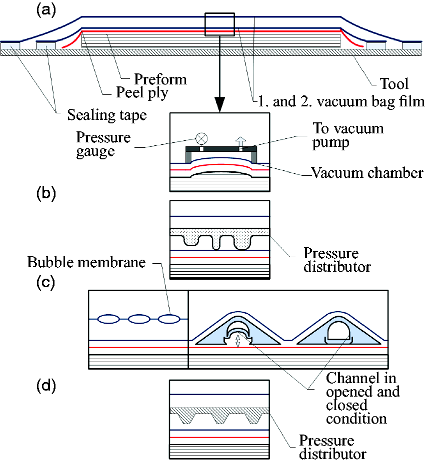
The pulsed infusion method (see Figure 4) is a method in which two vacuum bags are used. Between the first and second vacuum bag film, a pressure distribution medium is arranged, which can be designed depending on the component and forms local vacuum chambers. By evacuating the area between the first and second vacuum film, the first film is pressed into the local vacuum chambers, as in the VIPR process, and the resin can be distributed in the cavity. If the pressure is kept constant, the process is called static pulsed infusion. Dynamic pulsed infusion, on the other hand, is the term used to describe the process in which the area between the first and second vacuum bag films is alternately de-aerated and aerated.19,20
The patent 21 for the channel-assisted resin transfer moulding process (CARTM) also mentions a pressure distributor (see Figure 4) that works in a similar way. In addition, resin distribution channels are also described, which are placed inside the cavity on the fibre material and are essentially hollow profiles. For resin distribution, the channels can be opened and closed by differential pressure. If the channels are inserted into one mould half, the channels can also be used in closed moulds. In contrast to the vacuum-assisted differential pressure infusion method, which is the subject of the experimental study in this publication, the channels of the CARTM method are positioned within the cavity and therefore have direct contact with the resin.
For resin distribution, a reusable flow medium is used in the Fast Remotely Actuated Channel process (FASTRAC, see Figure 4), similar to the previously mentioned infusion procedures. A tool with grooves is placed between the first and second vacuum bag film. By aerating the cavity and simultaneously evacuating the area between the first and second vacuum bag film, the first vacuum film is pressed into the grooves of the tool. This creates flow channels in the cavity which have the groove geometry. For the infusion, the cavity is evacuated again, and the resin is distributed through the channels in the part. At the end of the infusion, the second vacuum bag is removed with the tool and the channels form back. 22 A more detailed overview of infusion processes is given in Hindersmann. 23
Innovative infusion process: vacuum-assisted differential pressure infusion
In conventional infusion procedures, sprue or resin distribution channels are used which are located within a cavity. The cavity in these methods is formed from a vacuum bag film and a rigid mould. The vacuum differential pressure infusion, however, uses resin distribution channels that are positioned outside of a cavity and can be temporarily activated by a differential pressure between the cavity and the channel. In principle, the channels consist of hollow profiles and the pressure level within the hollow space which can be adjusted by evacuating or pressurizing. Lower pressure in the channel than in the cavity deforms the vacuum bag film in the channel area. The lower pressure increases the permeability of the fibre material in the channel region and, depending on the channel geometry, provides an additionally superimposed pure resin channel.
The process flow is shown schematically in Figure 5. Before infusion, the pressure in the distribution channel p
VC
is equal to the atmospheric pressure p0, and both pressures are greater than the pressure in the cavity p
C
.
Schematic drawing of the vacuum-assisted differential pressure infusion.
23
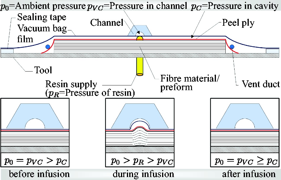
When the resin supply is opened, the resin flows into the cavity, and thus, the pressure within the cavity is equalized to the pressure of the resin p R . The pressure in the distribution channel is adjusted to a lower pressure than the resin pressure, and the difference between p R and p VC leads to deformation of the vacuum bag film. At the end of the infusion, the channel is pressurized to atmospheric pressure, and the film relaxes back to its condition prior to infusion.
The vacuum-assisted differential pressure infusion 24 as described before is an extension of an infusion process patented by van Herpt. 25 The enhancement towards the van Herpt method is that the pressure in the channels need not be lower than the pressure inside the cavity before infusion. In addition the channels are not permanently connected to the vacuum bag film, and a superimposed pure resin channel can be implemented depending on the distribution channel design. To infuse larger components, the channels can be arranged in diamond shape and the large surface can be divided into many individual areas. These individual areas are easier to impregnate than the large component surface.
Effects of the process on different laminate structures
An essential feature of the method is the positioning of the resin distribution channels on the fibre composite parts. For this reason, it is necessary that the channels leave no or only very weak marks on the cured component.
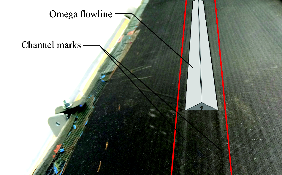
Figure 6 shows the marks on different CFRP laminates, which are created using conventional resin distribution channels (so-called Omega Flow Lines). Clearly visible are the bulges at the channel edge and the higher resin content in this area. In the middle of the channel, where the resin flows, there is also a much larger laminate thickness. This can be explained by a lower compression, due to the channel opening. At the channel edges the bulge occurs because of the bridging of the vacuum bag. As shown in Figure 7, marks even remain when channels are positioned on perforated sheets and combined with flow medium.
Channel marks of Omega Flowline for twill-, canvas-woven fabric, biaxial- and unidirectional fabric. The Omega Flowline area is indicated in grey. Channel marks induced by channels that are positioned on perforated sheets and combined with flow medium.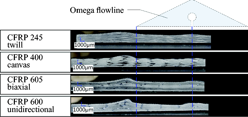
Used semi-finished products for the investigations of the channel marks.
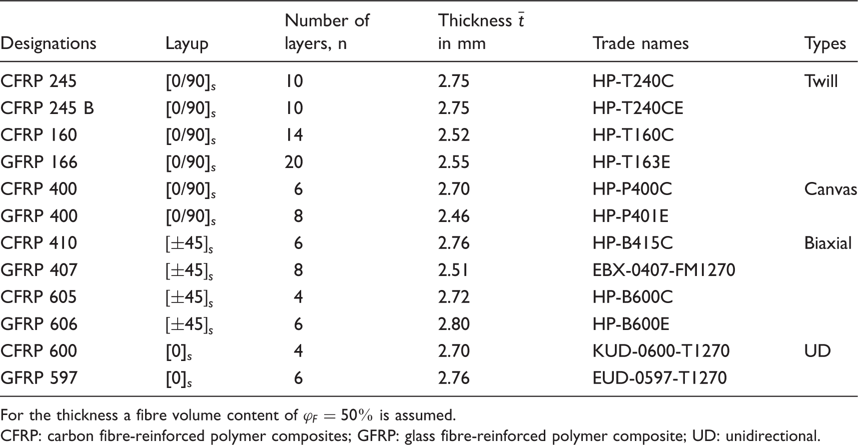
For the thickness a fibre volume content of
CFRP: carbon fibre-reinforced polymer composites; GFRP: glass fibre-reinforced polymer composite; UD: unidirectional.
For the examination of possible channel marks, the thickness of each material is determined outside and in the channel area by a tactile measurement. The mean value difference of these measured values indicates whether there is a material-dependent influence on the channel markings. To statistically secure these results, a significance test is applied to the mean difference. In addition, a tolerance range for the thickness variations is determined, and a visual comparison is performed with the help of micrograph studies.
Since the fibre density of the fibre materials and the basis weight of the semi-finished products are different, the respective number of layers must be varied to reach a mean total laminate thickness 
For the test procedure, the plies are stacked according to their number of layers n in a size of 250 mm × 200 mm. Subsequently, the preforms are air sealed with a vacuum bag. The resin distribution channel is positioned and sealed with adhesive tape in the middle of the fibre material. The channel has two vacuum connections, one is connected to the vacuum pump and the other to a pressure sensor. Three samples are always produced simultaneously in one vacuum bag, with the position (front, middle, back) being varied in each case (see Figure 8). As is the rule, two vacuum bag films are used for the infusion.
Test set-up for the manufacturing of the laminates for the determination of channel marks. The measuring points for the tactile thickness measurement after curing of the laminate are labelled, too. The distances between the points are a = 22.5 mm and b = 40 mm.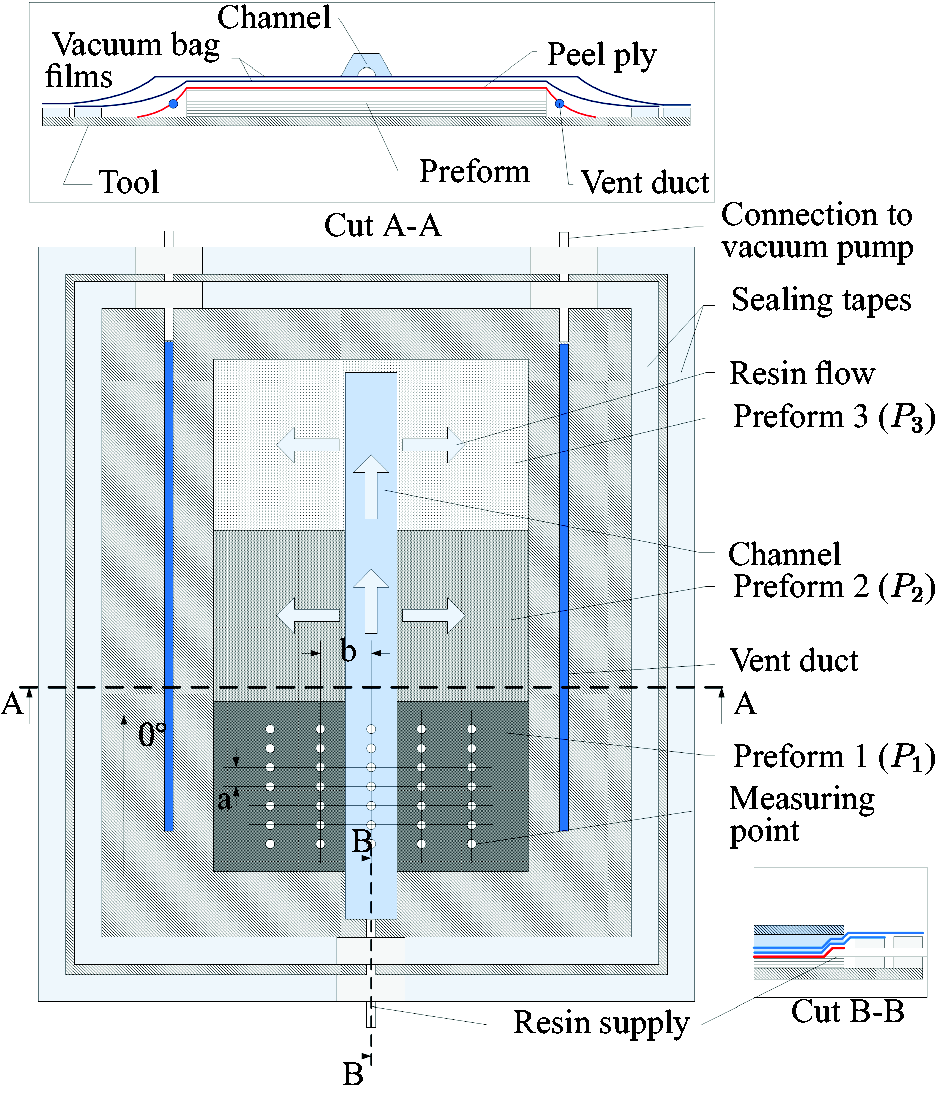
By the described procedure, each fibre semi-finished product is placed once in each position (front, middle, back) and a possible influence of the position is examined. The 0° orientation is in the channel's longitudinal direction, and the inner channel geometry is as described in more detail in Hindersmann. 26
In the experiment, the channel is evacuated simultaneously with the opening of the resin supply. This ensures that the fibre material is not deformed before the infusion. Once the entire fibre material is saturated, the pressure is equalized in the channel. The vent ducts are closed when they are completely filled with resin. Finally, the gate is closed. The volume of the vent duct is larger than the volume of the channel, and thus, it is ensured that the excess resin can flow out of the channel.
Tactile thickness measurement
In order to obtain a quantitative statement about the influence of the channels of the vacuum differential pressure method on the fibre materials, the thicknesses of the cured laminates are tactilely measured with a thickness gauge (electronic external measuring gauge C3R30 by Kroeplin), and an evaluation of micrographs from the channel region is made.
In the Figures 9 to 12, the measured thicknesses of the tactile thickness measurements for the samples are shown. In each case, the measured values of the undisturbed laminate area (left in light blue) are compared with the measured values of the channel (on the right in dark blue). Three samples have been prepared for each material. In addition, the fibre volume content from the thickness measurement for the laminate outside the channel region has been determined and expressed in percent.
Above: comparison of the mean values of the measured thicknesses between the undisturbed laminate area (light blue) and the channel area (dark blue) of the plates with Above: comparison of the mean values of the measured thicknesses between the undisturbed laminate area (light blue) and the channel area (dark blue) of the plates with Above: comparison of the mean values of the measured thicknesses between the undisturbed laminate area (light blue) and the channel area (dark blue) of the plates with Above: comparison of the mean values of the measured thicknesses between the undisturbed laminate area (light blue) and the channel area (dark blue) of the plates with 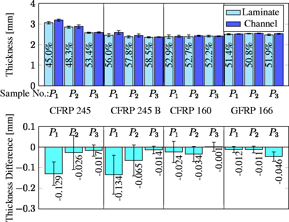
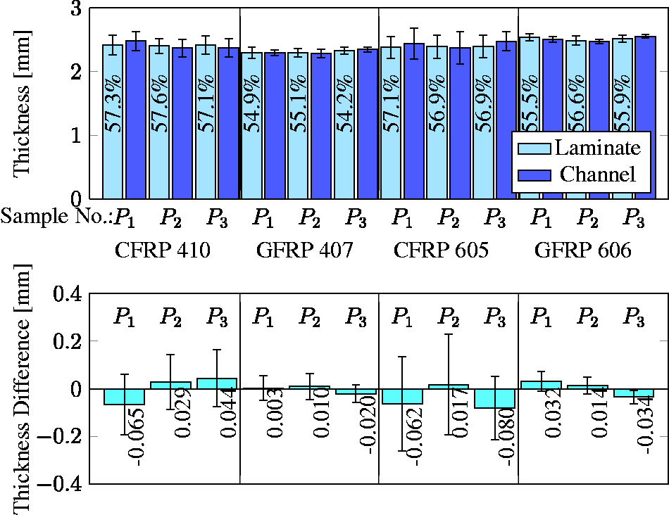
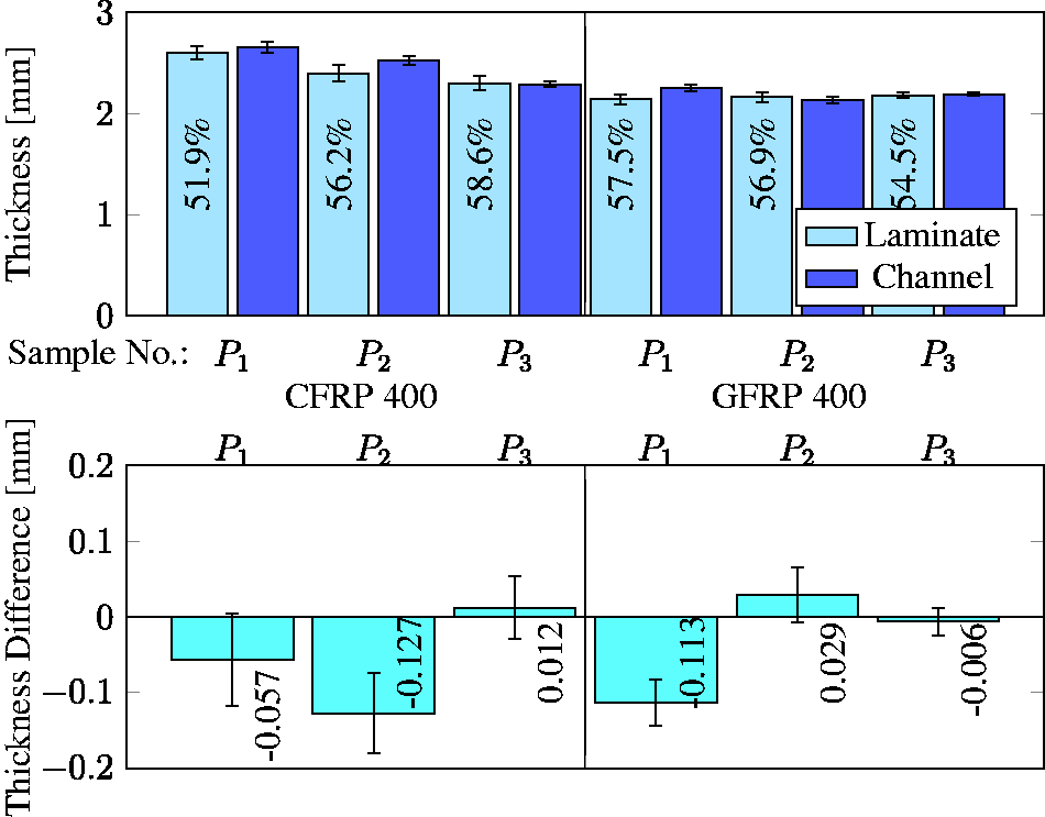
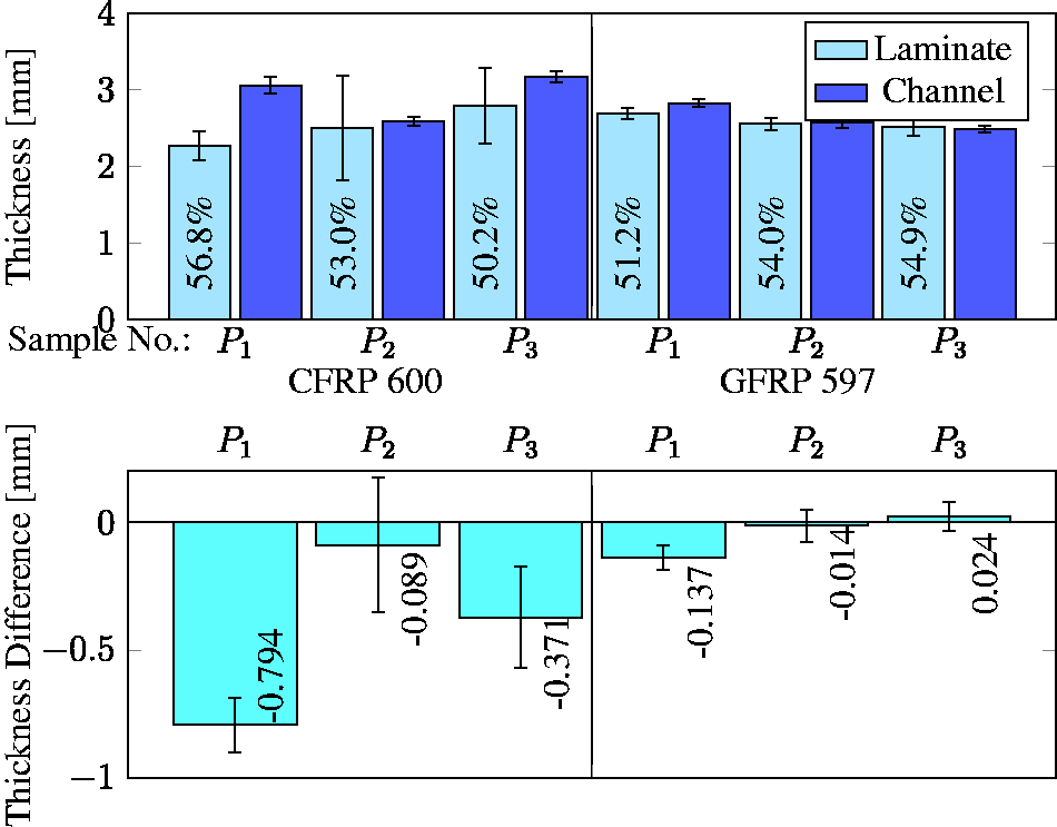
The lower part of the Figures 9 to 12 shows the thickness difference between the undisturbed laminate and the channel area. This thickness difference is determined by the equation (2). Therefore, for a negative difference 
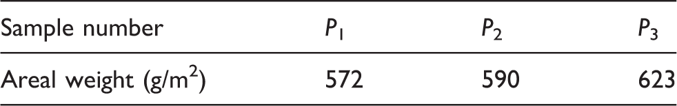
Calculated areal weights for unidirectional CFRP 600.
Due to the large area difference between channel and laminate area, there are fewer thickness measurement points in the channel area. Therefore, averages with different numbers of measurement points are compared. This makes it necessary to apply a significance test for the mean difference
As a statistical tool, the confidence interval for an average value difference can be used. Compared to the usual methods, such as a t-test, the significance can be shown very vividly. Based on Rasch et al.,
27
this requires the t-value 

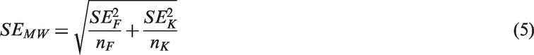
The standard error SE
MW
of the mean difference results from the standard errors for the channel area SE
K
and the laminate area SE
F
Number n of measured values (t-value from Rasch et al. 27 ).
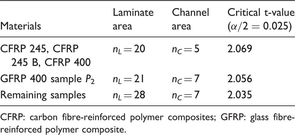
CFRP: carbon fibre-reinforced polymer composites; GFRP: glass fibre-reinforced polymer composite.
The required t-value 
With the correspondingly determined values, the t-value can be read from a t-distribution table, for example Table B in Rasch et al.
27
Here, the 95% confidence interval is used, so
The confidence interval shows no significance at least once for each examined material. However, this is just a statistical statement. For a practical relevance, the surface waviness of the samples needs to be measured, and thus, the mean differences are relativized.
Analysis of the surface waviness
Since the process under investigation is a vacuum bag process, a vacuum bag film forms the flexible mould part. Due to the flexibility of the vacuum film and the areal weight tolerance (with the materials used ± 5%), the undulations on the surface of the laminate arise. In addition, the figure Figure 13 shows that waviness can be caused by the stacking of the individual layers. In the left part of Figure 13, the rovings of the single layers are nested, whereas in the right part of the picture the rovings are aligned on top of each other. This results in thickness differences. By combining the two possibilities, the undulations on the surface of the laminate occur. The differences in thickness are caused by fluctuations in the areal weight, since the fabrication and handling process of the semi-finished products sets different distances between the fibres. When single layers are stacked to a preform, the offset stacking between the individual layers leads to areas where fibres are positioned superimposed or offset from each other. In addition, the individual layers, especially woven fabrics, have crossing points and distances between the crossing points (float). By layering and compressing the individual layers, the fibres of a single layer can slide into the area between the crossing points. At these points, the laminate is locally thinner than at the points where crossing points overlap.
Schematic representation of the stacking of single layers and resulting waviness.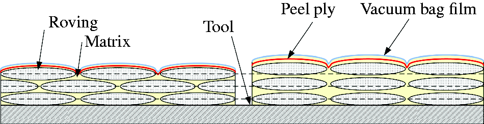
With a digital microscope (Keyence VHX 5000), it is possible to determine the surface topology of the material. In this optical measurement method, the depth information is determined by the depth of field automatic. As an example, the measured surface topology of a twill-woven fabric is shown in Figure 14. The waviness to be determined is superimposed by the surface roughness caused by the peel ply. In addition, the microscope also detects pores on the surface of the laminate and thus falsifies the measurement of the surface topology.
Surface topology of a twill-woven fabric GFRP 166 as an example.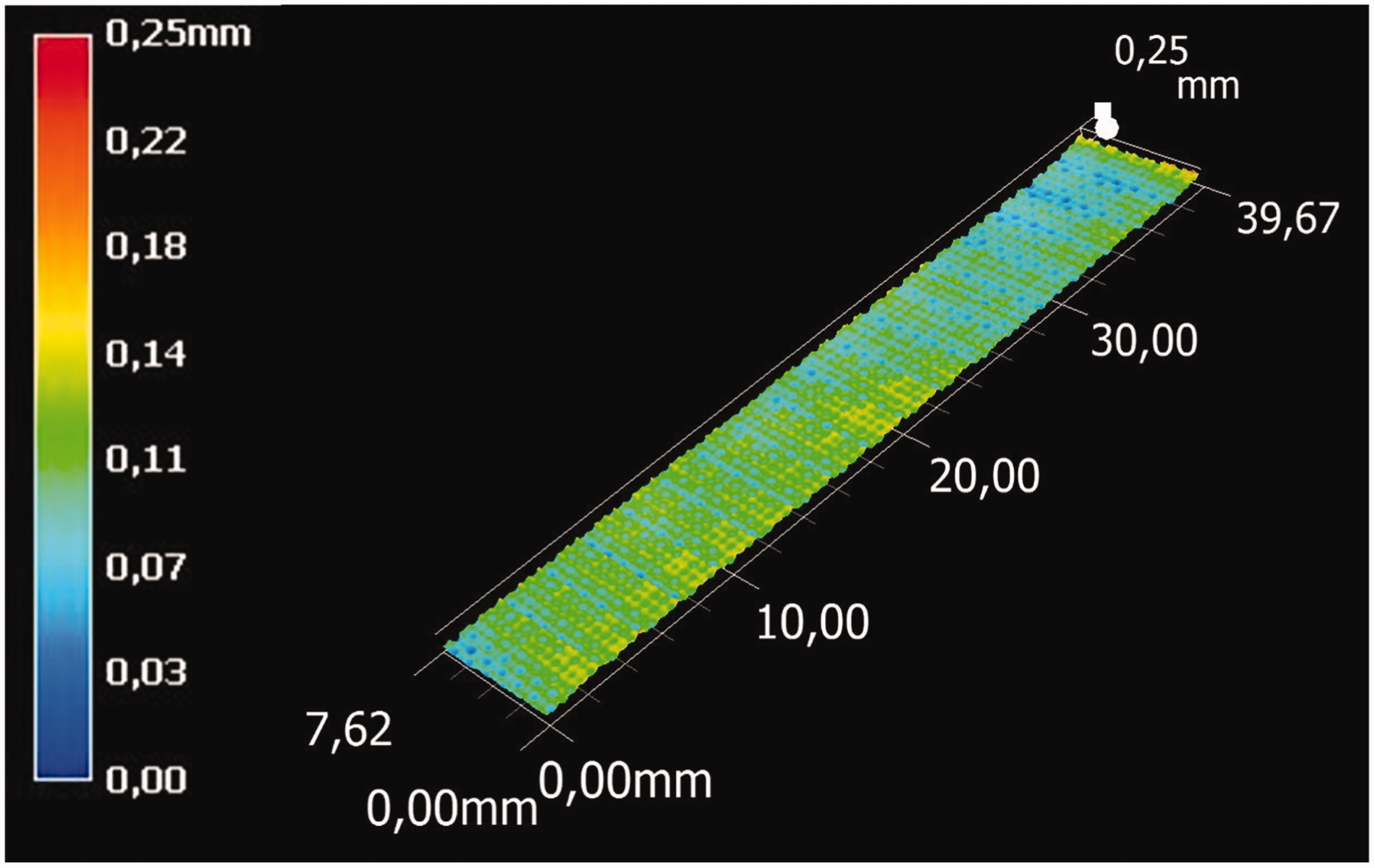
Based on Klein and Kiehl,
28
the surface waviness from the primary profile is determined by Gaussian low-pass filtering. The cut-off wavelength 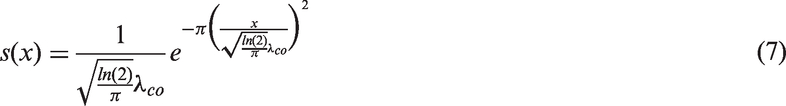
The roughnesses to be expected in the measurement are, according to Weiß et al.,
29
in the range of
The primary profile P, as exemplified in Figure 15 (green line), is averaged over the total sample depth. By application of the Gaussian filter, the waviness W shown in the lower part of Figure 15 is obtained. The wave depth Above: primary profile averaged over sample depth (green line). Below: waviness determined by Gaussian filter, for twill-woven fabric GFRP 166. Waviness values of the investigated fibre materials (average of three samples each, standard deviation in parentheses). CV: coefficient of variation; CFRP: carbon fibre-reinforced polymer composites; GFRP: glass fibre-reinforced polymer; UD: unidirectional.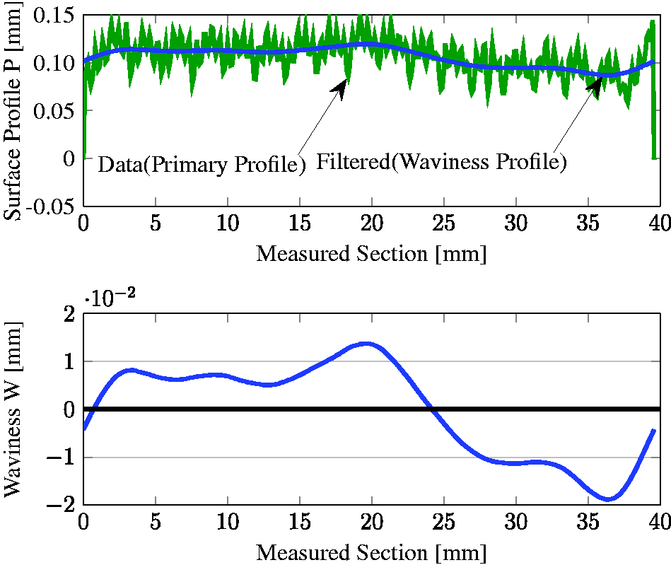
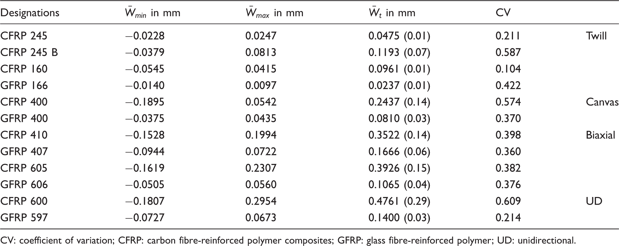
The mean difference between the laminate and channel area may fluctuate within the waviness depth because

According to equation (8), the upper and lower bounds must be
The mean difference may thus fluctuate within the values in Table 4. If these limits are not exceeded, no influence of the channel can be assumed. The values determined in this context are only to be understood as additional range estimates and are used to check the statistical significance test. However, the waviness test also shows that higher waviness values are present at higher standard deviations. This can be explained by the larger differences between the individual thickness measurements and thus higher variability with larger waviness. Therefore, in addition to the standard deviation, the coefficient of variance is also given in Table 4.
For the examined twill-woven fabrics, it can be seen that all samples which showed no significance in the statistical significance test are also within the limits of the surface waviness values. The influence of a binder on the undulations is shown by comparing the waviness values of the twill-woven fabric CFRP 245. In the case of unbonded material, the waviness is significantly lower, since the individual layers can slide off one another more easily.
The comparison of the waviness of the canvas-woven fabrics shows that all values are within the tolerance range. Due to the lower floatation and the higher areal weight, the waviness of the canvas-woven fabrics is significantly higher than the waviness of the twill-woven fabrics.
At the biaxial fabrics, all mean differences are within the surface waviness range. The sample P3 of GFRP 606 is to be considered as significant according to the significance test. However, the investigation of surface waviness shows that the waviness is much larger.
For the UD fabric CFRP 600, the mean difference of the sample P1 is outside the surface waviness. The samples P2 and P3 are within the waviness values. Similarly is the finding for the UD GFRP 597. Here, the samples P2 and P3 again lie within the waviness parameters.
The results of the investigation of the individual semi-finished products show that the infusion method does not cause a substantial change in thickness in either glass fibre or carbon fibre materials. Despite the different flexural stiffnesses of the materials, no marks remain on the material. This is also clear from the different laminate structures. Even with the orientation of the fibres in the channel direction (UD layer), with a low resulting bending stiffness transverse to fibre orientation, no significant effects of the method on the thickness are recognizable in the majority of the samples.
Visual comparison through a micrograph analysis
For further investigation on channel marks, a visual comparison is made between micrographs. For this purpose, micrographs of the channel region and of the undisturbed laminate are shown in the Figures 16 to 19. Additionally, the channel marks from Omega Flow Lines are presented.
Micrographs of twill-woven fabric. Micrographs of canvas-woven fabric. Micrographs of biaxial fabric. Micrographs of unidirectional fabric.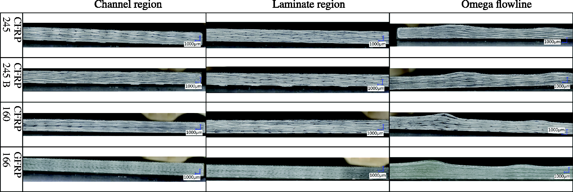
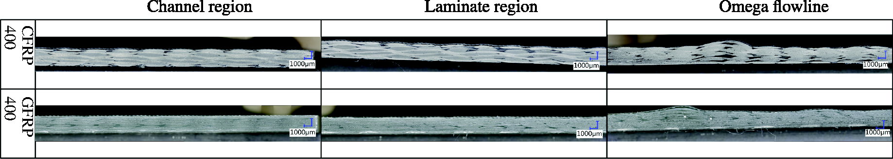
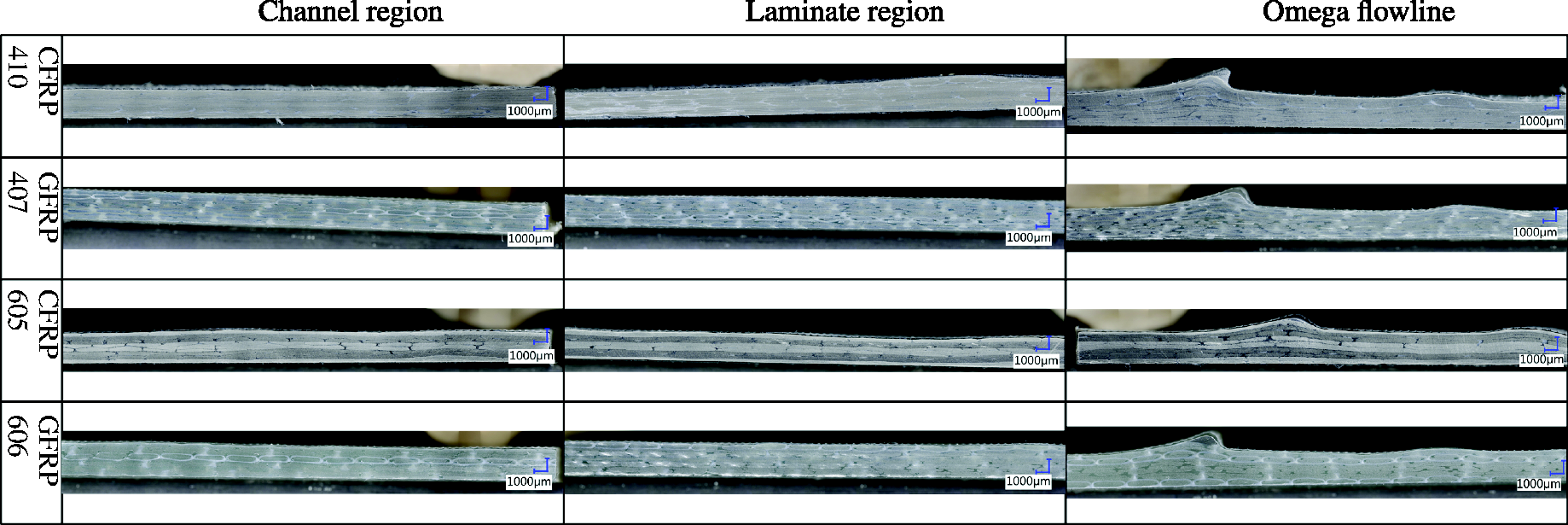
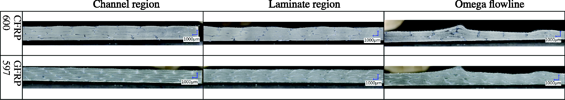
In contrast to the samples which have been produced with Omega Flow Lines, in the channel region of the new method, no fibre or pure resin accumulations can be seen. Furthermore, no differences between undisturbed laminate area and channel area of the new method can be observed. However, when comparing the UD fabric CFRP 600, the lower surface waviness in the channel area is noticeable (Figure 19). Presumably, loading the fibre material in the impregnated state results in improved stacking of the fibres as the sliding friction is reduced by the resin.
Summary and conclusions
The particular challenge in the presented work is to investigate something that actually should be prevented, the channel marks. Perhaps a better way would be to determine a process window in which the method works. By exceeding the process window limits channel marks occur and that could be shown easily. But when entering this path the process window and the requirements must be known, and these criteria are not met. Therefore, the suggested approach was chosen, and a tactile thickness measurement investigation, an examination of the surface waviness and a micrograph analysis was done.
Compared to the Omega Flow Lines the laminate structure is far less influenced by the resin distribution channels of the new infusion method. This is shown by the analysis of the micrographs. Therefore, the new method reduces the risk of shear buckling in the channel area, and the fibre volume content is not changed towards the undisturbed laminate area. In addition, the channels can be positioned in areas of the part surface where a functionality, e.g. adhesive surfaces, is necessary.
The results of the tactile thickness measurement investigations show that the method works good for nearly all of the evaluated materials. Only for the UD fabric CFRP 600 the findings are not clear. At two of three samples the statistical significance study shows significance but the P3 sample is within the waviness, and the micrograph analysis shows no significant influence of the channels. On the contrary, the waviness in the channel area seems to be reduced in the channel area compared with the undisturbed laminate. Even if the influence of the new method is lower than the effect of the Omega Flow Lines, further investigations are necessary for this fibre material.
By examining many different laminate structures and semi-finished fibre products, it is highly likely that the results can be transferred to other laminate structures. Even for UD fabric materials where the 0 ° direction is in longitudinal direction of the channel, the method does not or only marginally influence the laminate structure. At least this is true for UD glass fabric GFRP 597.
Footnotes
Declaration of Conflicting Interests
The author(s) declared no potential conflicts of interest with respect to the research, authorship, and/or publication of this article.
Funding
The author(s) received no financial support for the research, authorship, and/or publication of this article.