
Abstract
The fatigue life and damage tolerance of composite stiffened panels with indentation damage are investigated experimentally using single-stringer compression specimens. The indentation damage was induced to one of the two flanges of the stringer of every panel. The advantages of indentation compared to impact are the simplicity of application, less dependence on boundary conditions, better controllability, and repeatability of the imparted damage. The tests were conducted using advanced instrumentation, including digital image correlation, passive thermography, and in situ ultrasonic scanning. Specimens with initial indentation damage ranging between 32 and 56 mm in length were tested quasi-statically and in fatigue, and the effects of cyclic load amplitude and damage size were studied. A means of comparison of the damage propagation rates and collapse loads based on a stress intensity measure and the Paris law is proposed. The stress intensity measure provides the means to compare the collapse loads of specimens with different damage types and damage sizes, while the Paris law is used to compare the damage propagation rates in specimens subjected to different cyclic loads. This approach enables a comparison of different tests and the potential identification of the effects that influence the fatigue lives and damage tolerance of postbuckled structures with defects.
Introduction
Composite structures can sustain a high degree of deformation during impact without developing visible cracks, even though the internal substructure is damaged. Thus, the traditional reliance on visual detection to find damage, which worked well for metal skins that dent easily, is inadequate for composite airframes. Therefore, the design and certification of a composite airframe must rely upon a thorough understanding of the strength and life reductions caused by barely visible impact damage (BVID).
Typical aeronautical stiffened panels can safely work in the postbuckling regime, but their collapse mode is quite complex, as it is due to the interaction of the postbuckling deformation with different failure modes, such as intralaminar damage, delamination, skin–stringer separation. The phenomenon is even more complex when fatigue loads are considered in the postbuckling regime and when defects such as impact damage are present. However, few experimental studies that consider the postbuckling behavior of composite stiffened panels with impact damage under static and fatigue loads1–10 are available in the literature, mostly because these tests are complex and expensive to conduct.
The present authors have studied the damage tolerance and fatigue life of postbuckled structures using a single-stringer compression (SSC) specimen that represents the response and failure of a corresponding multistringer panel. The relative simplicity of the SSC specimen results in relatively low manufacturing and testing costs, and a size that is computationally tractable.11,12
The test campaign presented in this paper represents phase IV of an experimental and numerical effort to investigate the effect of defects on the damage tolerance and fatigue life of SSC specimens. Phase I of this testing effort, conducted in 2009, provided an initial indication of the effect of defect size on the collapse loads of SSC specimens.12,13 Those test results were also used to validate a shell-based progressive damage finite element model. The phase II test campaign was performed in 2011 with additional instrumentation that included detailed ultrasonic testing (UT) of the specimens as well as of the use of digital image correlation to measure the postbuckling deformations during the test and a high-speed camera to understand the collapse sequence. The initial geometric imperfections of the panels were measured before loading using a coordinate measurement machine. 14 Fatigue tests were conducted in phase III in 2013. The instrumentation was expanded to include passive thermography and in situ UT.15,16 The specimens in phases I and II were fabricated at the Politecnico di Milano in two different batches. Those for phases III and IV were made in one batch by an established aerospace manufacturer of aerospace composite structures. The first test campaign was performed at the Politecnico di Milano, while testing of the subsequent three phases was conducted at the NASA Langley Research Center.
This paper describes the results of experiments conducted in phase IV of this effort. In contrast with the previous test campaigns, where initial bond defects were induced by placing a Teflon film between the skin and one of the stringer flanges, the initial damage in phase IV was induced to the panel by quasi-static indentation by a process described in “Indentation damage” section. The experimental procedures and instrumentation used are described in the subsequent section. Five specimens were tested. One specimen was subjected to quasi-static loads until collapse, and four specimens were subjected to fatigue loading cycling in postbuckling regime (“Quasi-static test” and “Fatigue tests” sections). The use of the Paris fatigue propagation law with an empirical stress intensity measure is described in “Comparison of fatigue damage propagation” section. Applying the Paris law in the manner described is useful to perform comparisons of the fatigue propagation rates of different damage sizes and cyclic load amplitudes. Finally, in the last section of this paper the stress intensity measure at collapse is applied to compare the collapse loads of all the specimens tested in the experimental phases I–IV.
SSC specimen
The SSC specimen was developed by the authors as a cost-effective alternative when studying the response and the failure of a multistringer panel loaded in compression. 12 The SSC specimen represents an intermediate level of complexity between coupon-level specimens and structural components while exhibiting most of the response characteristics of a corresponding multistringer panel. The experimental and numerical advantages of the SSC specimen are the low manufacturing and testing costs and the moderate computational requirements.
The SSC specimen is composed of a skin and a hat-shaped stringer. The dimensions of the test section of the specimen are shown in Figure 1. The skin consists of an eight-ply quasi-isotropic laminate with a stacking sequence of [45°/90°/−45°/0°]S and a total thickness of 1 mm. The stringer consists of a seven-ply laminate with a symmetric stacking sequence of [−45°/0°/45°/0°/45°/0°/−45°], which results in a nominal thickness of 0.875 mm. The skin and stringer are cocured in an autoclave and the material is IM7/8552 prepreg tape. Tabs for load introduction are potted and machined at the ends of the specimen after the curing cycle. A more detailed description of the SSC specimen can be found in the literature.12–16
Single-stringer compression specimen (all dimensions in millimeter).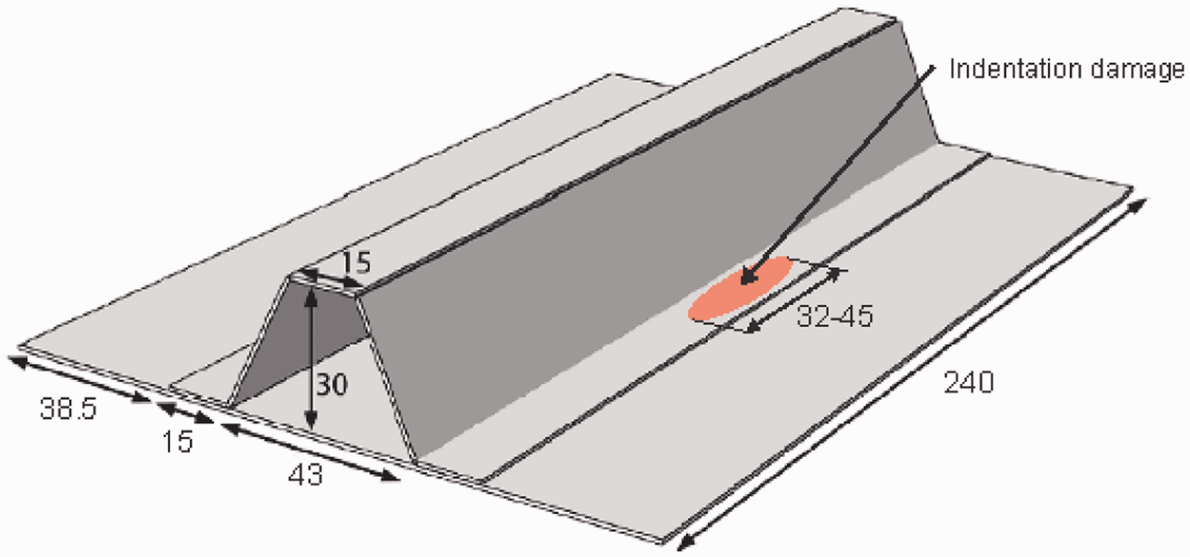
Indentation damage
In the present test campaign, damage similar to BVID was induced to the skin side of the panel by quasi-static indentation. The advantages of indentation compared to impact include the simplicity of application, less dependence on boundary conditions, better controllability and repeatability of the imparted damage, and the ability to reindent at the same location to increase the extent of damage, if needed. The hydraulic indenter used in this work is shown in Figure 2. The radius of the hemispherical indenter is 12.7 mm. The specimens were indented from the skin side at the mid-span of the specimen.
Hydraulic indenter used to induce initial damage onto flange of SSC specimens.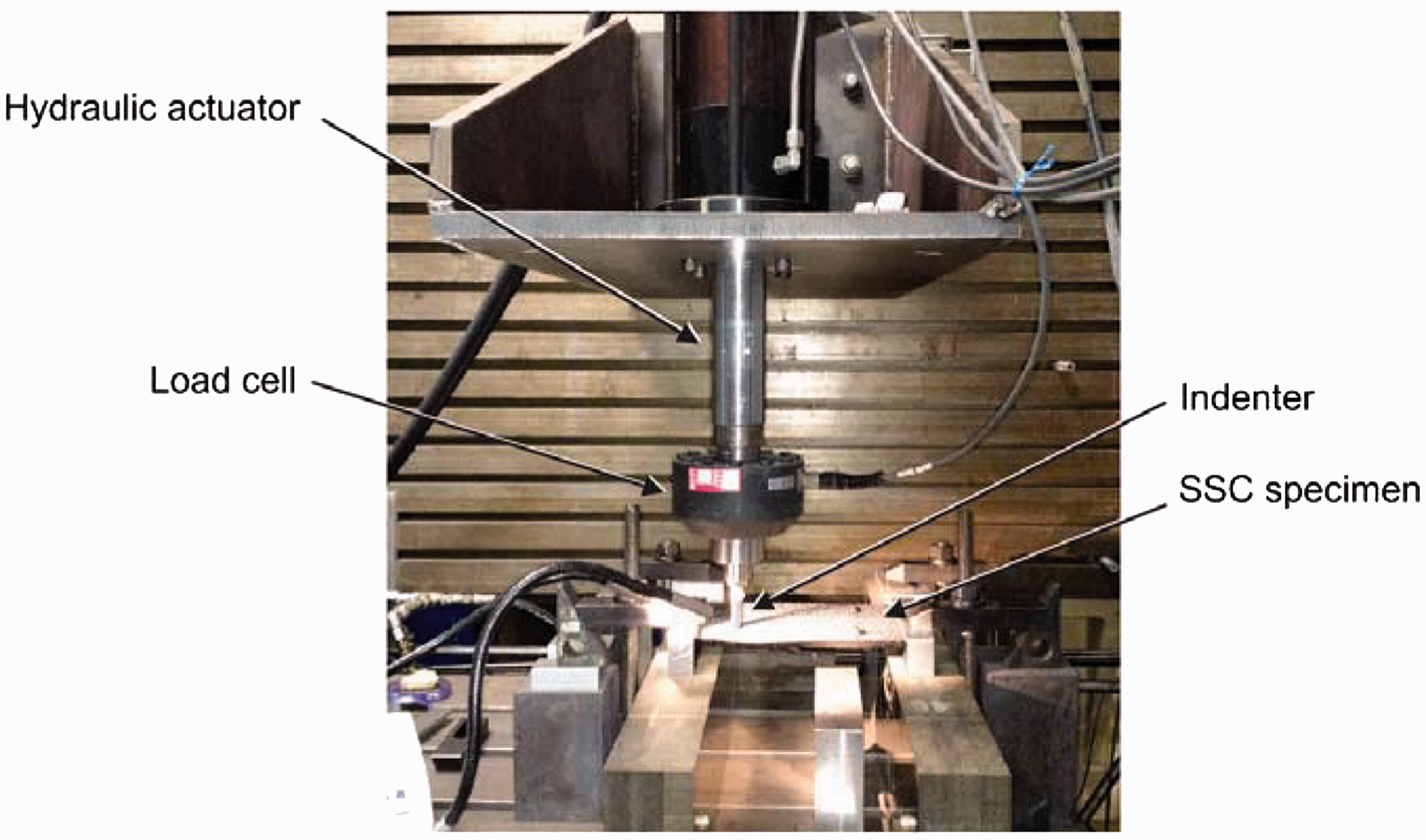
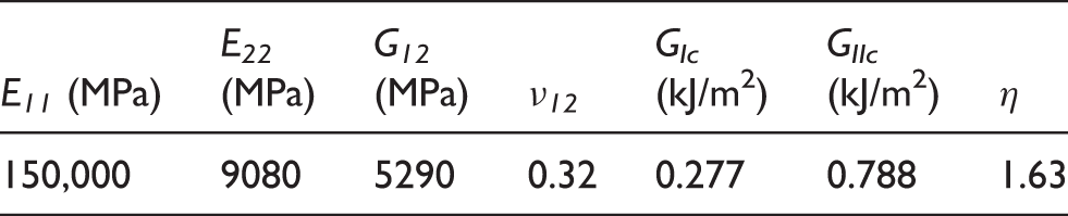
Material properties of IM7/8552.
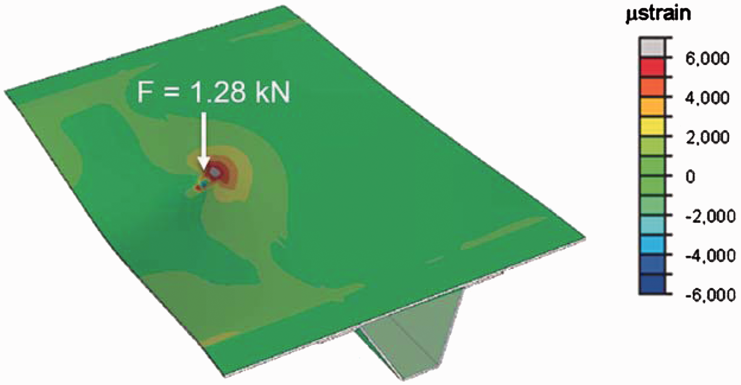
Strain plot for finite element damage model of indentation with an applied load of 1.28 kN.
Five specimens, referred to as SSCS-1–5, were tested. Specimens SSCS-1 and SSCS-5 were indented under the flange termination (edge indentation), and the three remaining specimens were indented at the center of the flange (center indentation). Representations of the locations of both indentations are shown at the top of Figure 4.
Force–displacement curves of indentations performed on specimens SSCS-1–5.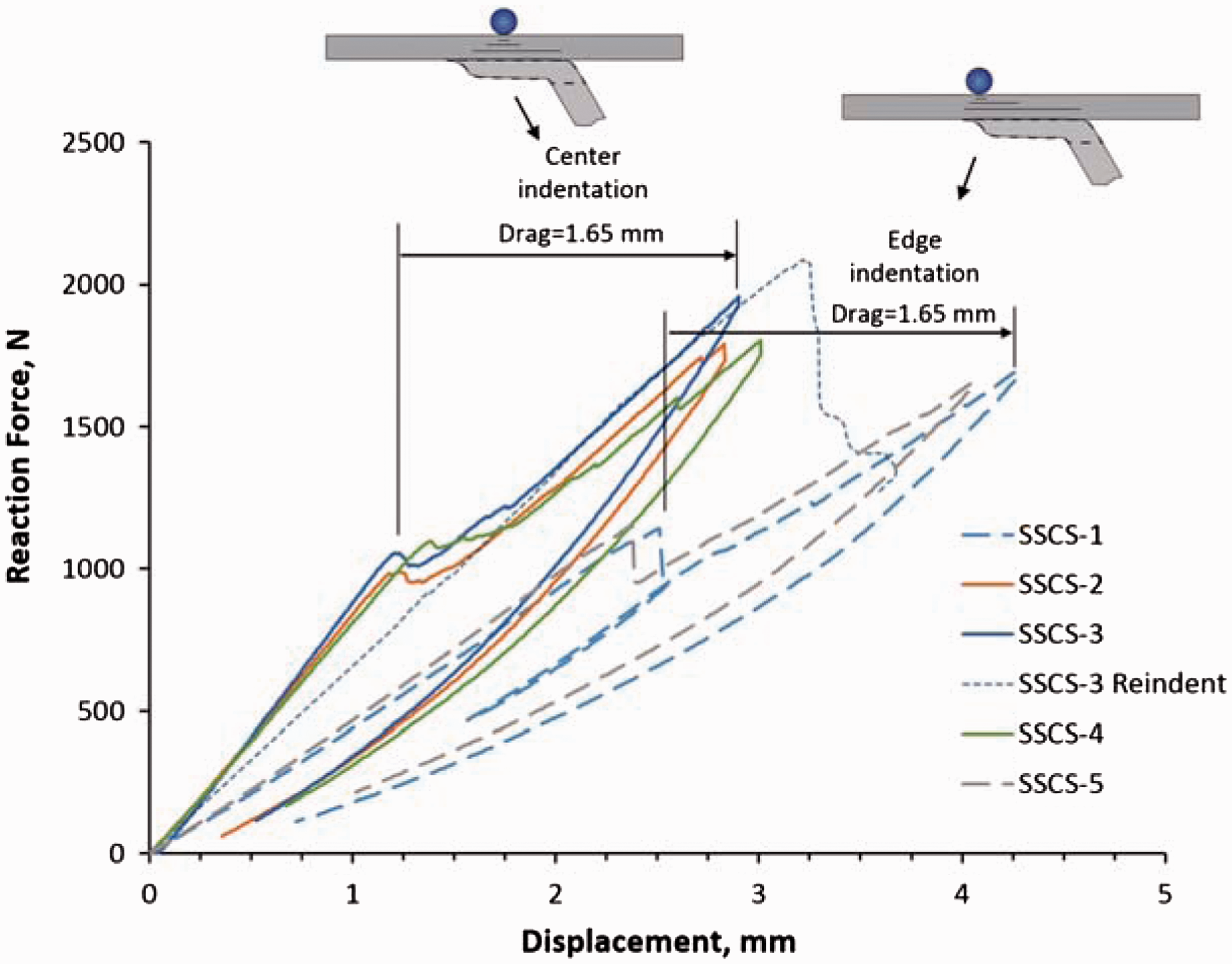
The desired dimension of the indentation damage was based upon the results of the test campaign in phase III 16 in which Teflon films were used as delamination initiators. The experimental results had shown that when loaded to approximately 80% of the collapse load, the SSC specimens with rectangular 40 mm-long Teflon inserts exhibited fatigue lives of a few tens of thousands of cycles. In contrast, the specimens with 20 mm Teflon inserts exhibited insensitivity to fatigue, even at loads approaching the collapse load. Therefore, a target indentation damage size of approximately 40 mm was selected.
To determine the indenter force/displacement required to obtain the desired damage size, a survey was conducted using undamaged portions of previously tested specimens. It was found that the size of the damage, measured along the length of the stringer flange and referred to herein as damage length, correlates better with the displacement of the indenter after the first load drop than it does with the applied load. This displacement of the indenter after damage initiation is referred to herein as “indenter drag.”
For the specimens in the current study, an indenter drag of 1.65 mm was used. Indentation was applied at one of two locations: at the center of the flange and at the edge of the flange. The load–displacement responses of the indentation process for all five specimens are shown in Figure 4. Although the center and edge indentation points are only 7 mm apart, the stiffness of the response for center indentations is considerably higher than that for edge indentations, as can be observed in Figure 4.
UT images of the induced indentation damage for the five specimens are shown in Figure 5 with arrows illustrating the damage length in millimeter. An indenter drag of 1.65 mm induced a damage length of approximately 45 mm along the skin–stringer interface for the edge indentations, and approximately 35 mm for the center indentations. The longer damage length for the edge indentations, compared to the center indentations can be observed in Figure 5.
UT images of damage induced in specimens SSCS-1–5 by indenting at either the edge or the center of stringer flange. UT: ultrasonic testing.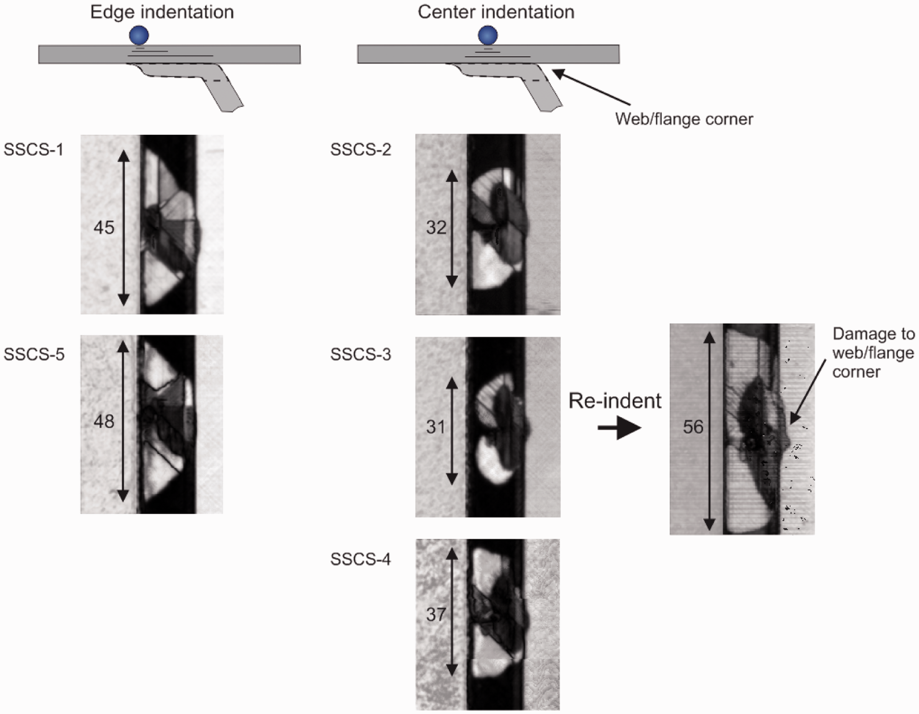
The damage length obtained by indenting SSCS-3 was considered too small for fatigue testing, so it was reindented using the same procedure as for the initial indentation. However, the initial 31 mm damage length grew unstably to 56 mm during reindentation. Additional damage was also observed at the web/flange corner, as called out in Figure 5.
Because previous test campaigns conducted on SSC specimens had shown that nominally identical specimens have small imperfections and that these small differences in initial shape can result in vastly different postbuckling deformations,13,14 the flatness of the skin of the specimens after the damage indentation was measured using the VIC-3D digital image correlation system.
18
In order to capture more detail, the depth of the indentation was also measured in a coordinate measuring machine (CMM), as shown in Figure 6. The resolution of the measurements taken with the laser scanning head shown in the figure is approximately 10 µm.
Laser scanning of indentation damage with CMM. CMM: coordinate measuring machine.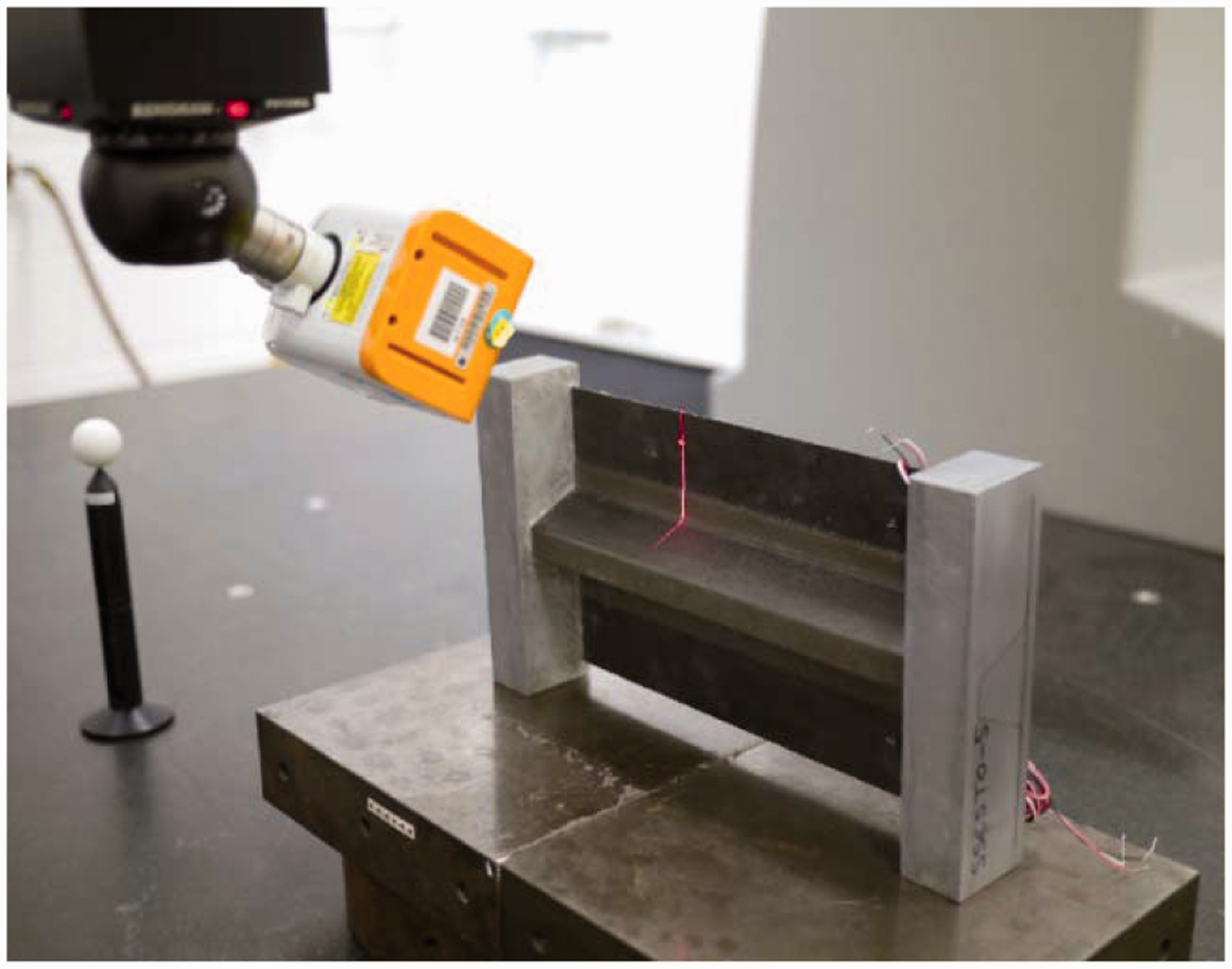
A typical out-of-plane initial deformation of the skin measured with VIC-3D is shown in Figure 7(a). The nonflatness of the skin is mostly due to the residual thermal strains that develop from the curing process. It can also be observed that the panel has a slight twist. The amplitude of the deformations is approximately 0.4 mm, which is 40% of the skin thickness. A typical result from the CMM that provides details for the residual dent depth is shown in Figure 7(b). The residual indentation depth is approximately 0.1 mm.
Global and local out-of-plane deformation after indentation for specimen SSCS-3. (a) Panel initial imperfection from VIC-3D and (b) local indentation depth measured from CMM. CMM: coordinate measuring machine.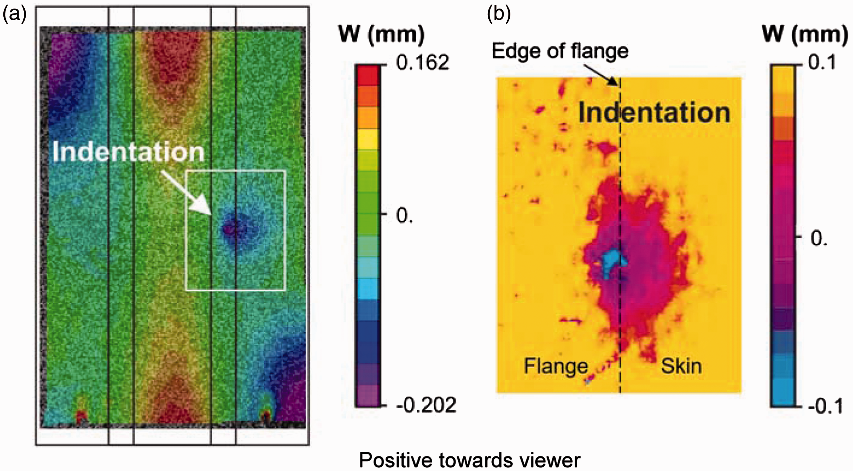
Experimental procedure and instrumentation
The five SSC specimens with indentation damage were tested to study the evolution of damage under quasi-static and fatigue compression loads. A quasi-static test was performed on one of the specimens, and the other four specimens were tested in fatigue by cycling into postbuckling at a load ratio (Pmin/Pmax) of R = 0.1, which allows a full cycling of the postbuckling deformation, yet keeps enough load on the panel to prevent it from walking on the platen. A loading rate of 2 Hz was selected as a compromise that is slow to allow observation with thermography and digital image correlation, yet is fast enough to limit the time required for the completion of the tests.
The tests were conducted using a uniaxial test frame and with instrumentation that allows a precise evaluation of the postbuckling response and damage. The test frame and the instrumentation shown in Figure 8 is the same as used in the previous test campaign conducted on SSC specimens with Teflon films and described in Dávila and Bisagni.
16
The primary instrumentation consists of (i) two three-dimensional digital image correlation (VIC-3D) systems
18
that are used to measure the postbuckling full-field deformations and strains on the skin and stringer sides of the specimen, (ii) an infrared camera for the passive thermal monitoring
19
with a frame rate of 60 Hz that can track the position of a delamination front during fatigue cycling, and (iii) an in situ UT scanner
20
mounted on the load frame which is used to obtain detailed measurements of the damage. The digital image correlation system acquired images at a rate of 0.2 Hz, the infrared camera at 60 Hz, and the UT scanner at selected intervals. Finally, two back-to-back pairs of strain gauges placed on the skin near the top of the specimen were used to ensure that the load introduction platen was properly aligned.
SSC specimen, load frame, and test instrumentation.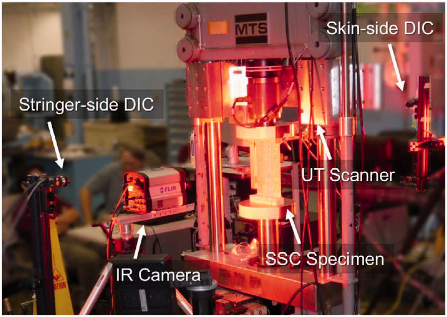
Quasi-static test
Experiments conducted in the previous test campaign (III) indicated that SSC specimens with 40 mm-long Teflon-induced defects could sustain tens of thousands of cycles at a maximum cyclic load equal to 80% of the quasi-static strength before collapsing. 16 Therefore, a quasi-static test to failure of specimen SSCS-2 was performed to establish a maximum load for subsequent fatigue tests. The initial response of specimen SSCS-2 was linear. This linear response was quickly followed by a transition into the postbuckling range that was progressive and devoid of snap-through and, as such, it was difficult to clearly identify a buckling load. The out-of-plane deformations increased gradually in the postbuckling regime.
The postbuckling deformation was characterized by a mode composed of three half waves along the length in the skin on both sides of the stiffener. The deformation at a load of 34.5 kN immediately before collapse is shown in Figure 9 using the out-of-plane displacements measured by the digital image correlation system. The deformation was symmetric with respect to two orthogonal planes and no damage was detected. The maximum amplitudes of the out-of-plane displacements at the center of the free edges were approximately 3 mm in the direction opposite to the viewer. The specimen collapsed suddenly, and the failure was characterized by a separation of the stringer from the skin at the mid-length. The collapse load magnitude of 34.5 kN was used as an upper bound when determining the loads at which the fatigue tests were run.
Out-of-plane displacement during quasi-static test of specimen SSCS-2 taken with VIC-3D from stiffener side immediately before collapse (34.5 kN).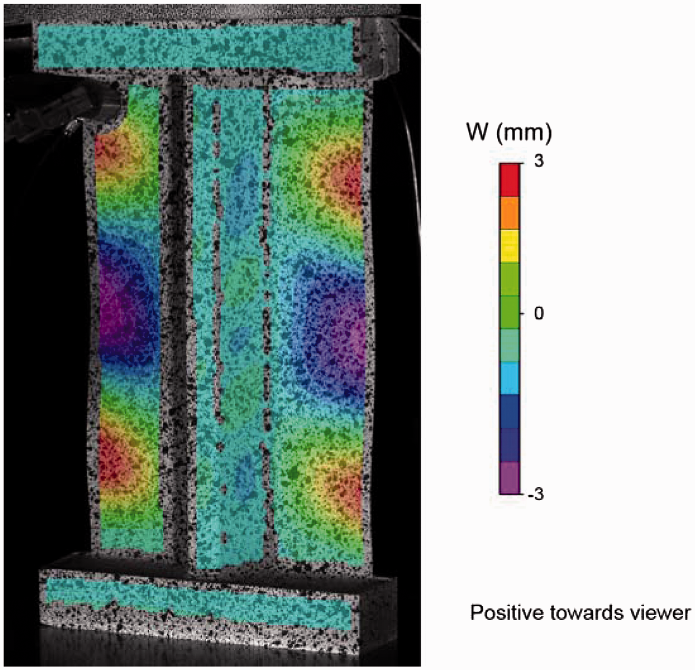
Fatigue tests
The fatigue tests were conducted in stages consisting of a number of load cycles of a constant load amplitude followed by a UT scan. In between the fatigue stages, a quasi-static test with a load amplitude equal to the load for the next fatigue stage was performed for a precise measurement of the deformation of the panel using VIC-3D. The number of cycles to be performed within a particular stage and whether to increase the load amplitude were chosen by examining the rate of damage growth. When the damage was found to propagate too slowly, the loading amplitude was increased. A practical propagation rate is one that causes collapse in fewer than 100,000 cycles.
In addition to the UT scan at the end of each stage, passive thermography was used to track the evolution of damage during a stage. The real-time information from the thermography was used to determine additional stopping points during the fatigue tests to ensure that critical stages of the damage evolution were recorded with UT scans. The real-time information provided by passive thermography was particularly important near the end of the tests, when the rate of propagation increases rapidly.
An image captured by the digital image correlation system on the skin side of a typical panel (SSCS-1) after 96,000 load cycles is shown in Figure 10(a). When subjected to a load of 31.1 kN, the maximum out-of-plane displacement is equal to 3.42 mm in the direction opposite to the stringer and 1.79 mm in the direction of the stringer. It can be observed that the deformation is similar to that for panel SSCS-2 but of opposite amplitude. Differences in the postbuckling response of two nominally identical specimens are common and attributable to small differences in the initial imperfections of the panels and, possibly, to minute differences in the alignment of the specimen in the test platens. Therefore, it is extremely difficult to predict the mode that will develop in a particular panel.
Fatigue and posttest assessment of specimen SSCS-1: (a) deformation at 96,000 cycles and (b) after collapse.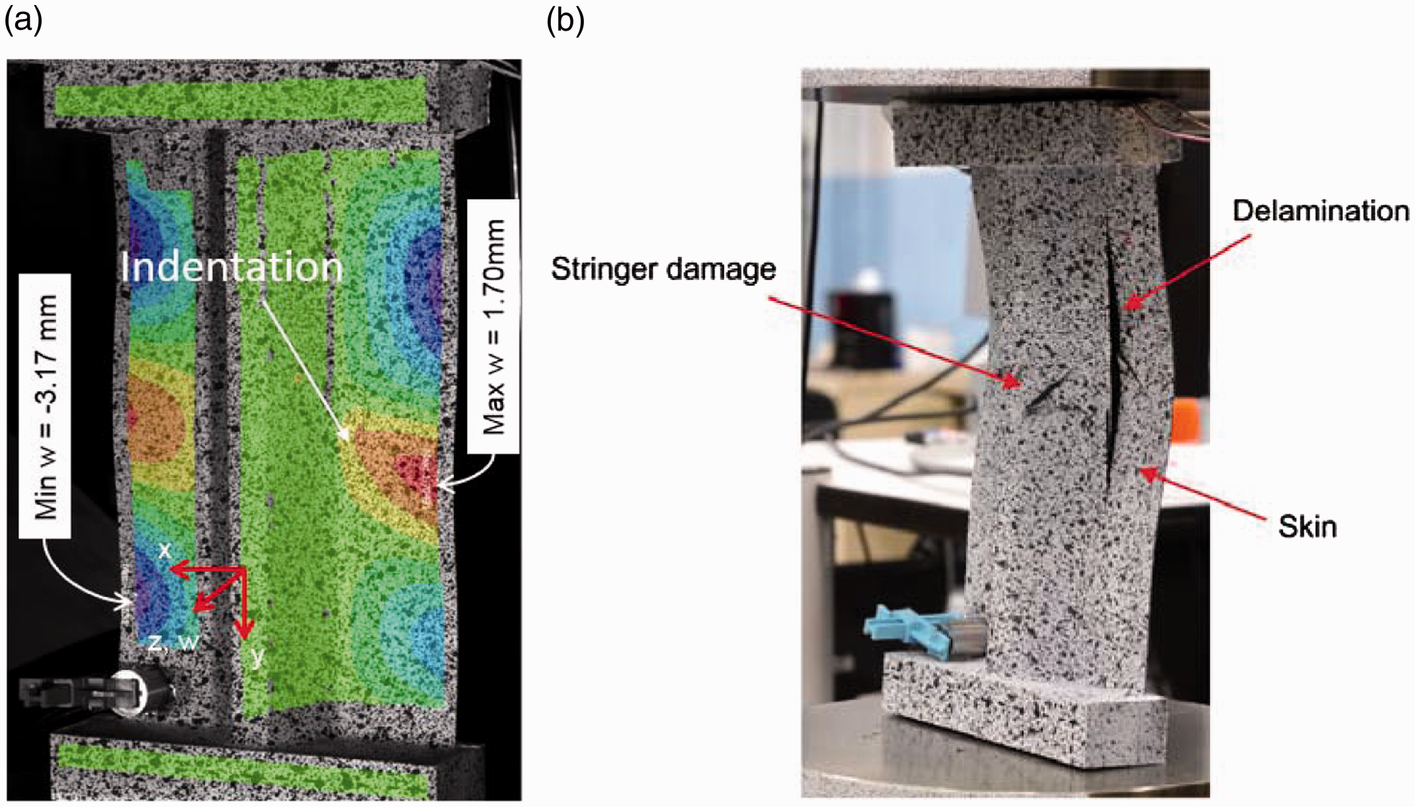
Specimen SSCS-1 failed suddenly at 117,506 cycles as a consequence of an unstable delamination between the skin and both stringer flanges. The posttest deformation is shown in Figure 10(b), where it can be observed that there is separation at the skin–stringer interface and crippling damage in the stringer.
Quasi-static load-shortening curves for specimen SSCS-5 are shown in Figure 11, which is representative of what was observed for all specimens. It can be seen that the initial response is nearly identical to that at 20,000 and 30,000 cycles. Clearly, the global response of the SSC specimens retains a constant nonlinearity and is only mildly affected by the progression of fatigue damage. The specimen collapsed at 33,623 cycles.
Quasi-static load-stroke curves at three stages of the fatigue life of specimen SSCS-5.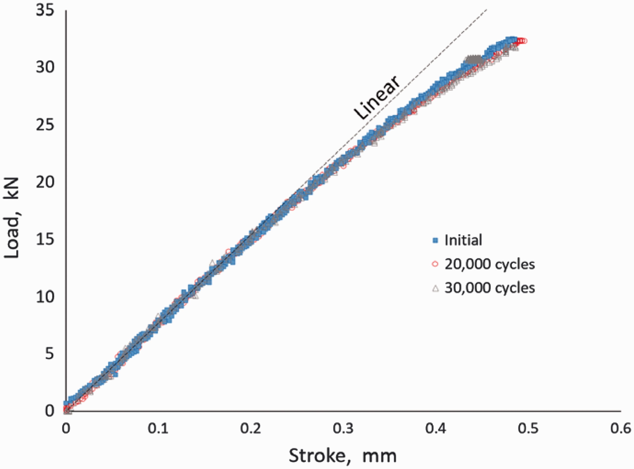
As was described earlier, the fatigue tests were conducted in stages so that UT scanning of the indented area of the panel could be performed at regular intervals. To illustrate the typical propagation of damage, a sequence of images for SSCS-4 obtained by the UT scans immediately after indentation and at 12,000, 36,000, and 78,000 cycles are shown in Figure 12. The images show an extension of the initial skin–stringer separation along the length of the specimen. Collapse of the specimen occurred at cycle 78,135, shortly after the last image was taken.
UT images showing damage propagation for specimen SSCS-4 at different cycle counts. UT: ultrasonic testing.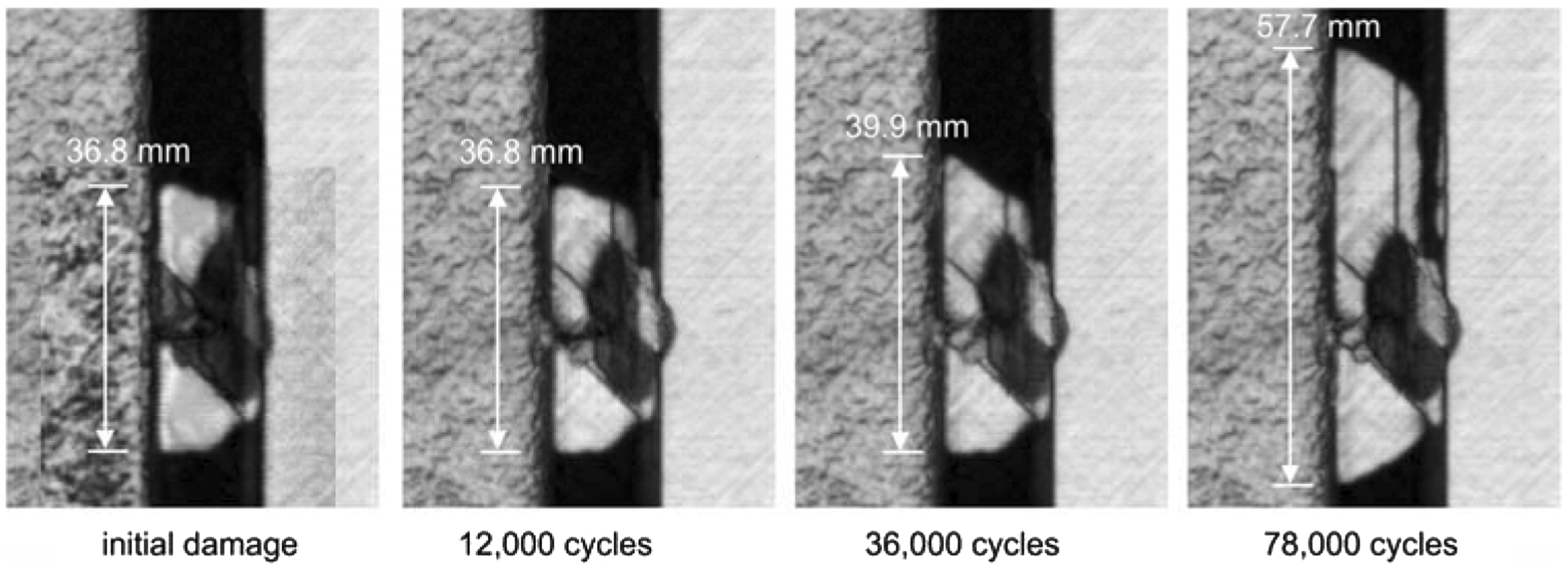
To examine the morphology of the damage, the UT scan of specimen SSCS-4 at 78,000 cycles was processed and colorized according to “time of flight” (TOF). TOF is the delay between the emitted ultrasonic sound wave and the reflected echo, which is a relative measure of the depth of the surface closest to the probe. The resulting image, shown in Figure 13, identifies the depth of the various delaminations. Five cross-sections of the skin and stringer flange are examined. The results indicate that only two delaminations propagate during cyclic loading and that both delaminations propagate together: one interface is at the skin–stringer interface, and the other one is one-ply deep into the stringer flange, at the −45/0 interface. The smaller delaminations in the skin do not appear to grow under fatigue.
UT images using “time-of-flight” processing for depth location of delaminations (SSCS-4). UT: ultrasonic testing.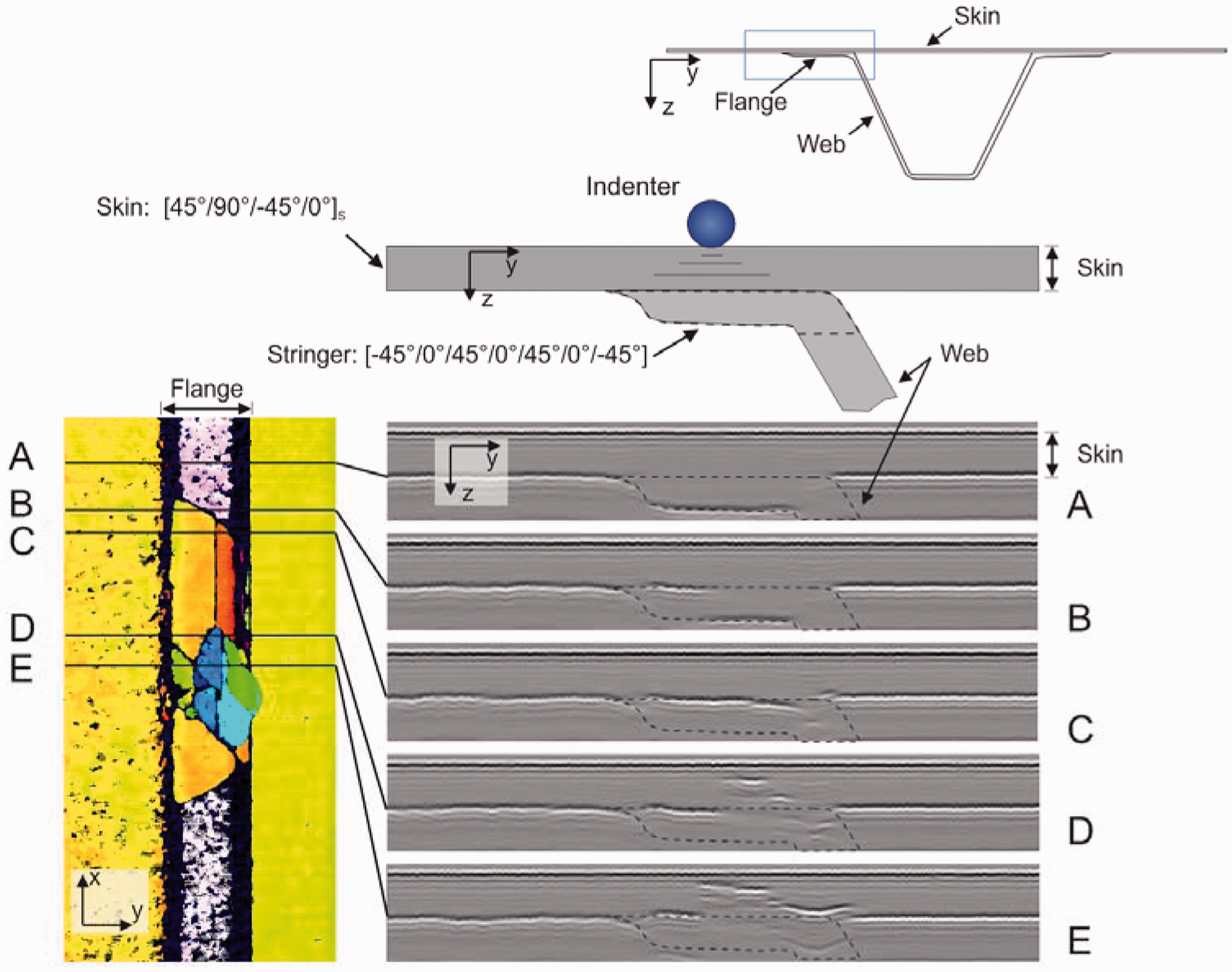
Although passive thermography was intended for estimating the size of the damage zone during fatigue loading, it was found to be particularly capable for capturing the sequence of damage events that occur during collapse. The sequence of three infrared images shown in Figure 14 illustrates the collapse of specimen SSCS-4 after 78,135 cycles. The heating, represented by lighter regions of the image, can be seen at the strain gauges and along the delamination front at the skin–stringer interface. The postbuckling deformation of the stringer appears as oblique lines in Figure 14(a). A faint outline of the damage at the skin–stringer interface can also be observed. A UT image of the damage zone recorded after 78,000 cycles is shown for comparison, and the area of the UT scan is highlighted with the blue rectangle in Figure 14(a). Note that the thermal image was captured from the stringer side of the specimen, while the UT scans were performed from the skin side of the specimen. Therefore, the UT image was flipped horizontally to match the orientation of the infrared image.
Infrared images illustrating sequence of collapse (SSCS-4). (a) Delamination reaches critical size, (b) unstable tunneling, and (c) stringer crippling.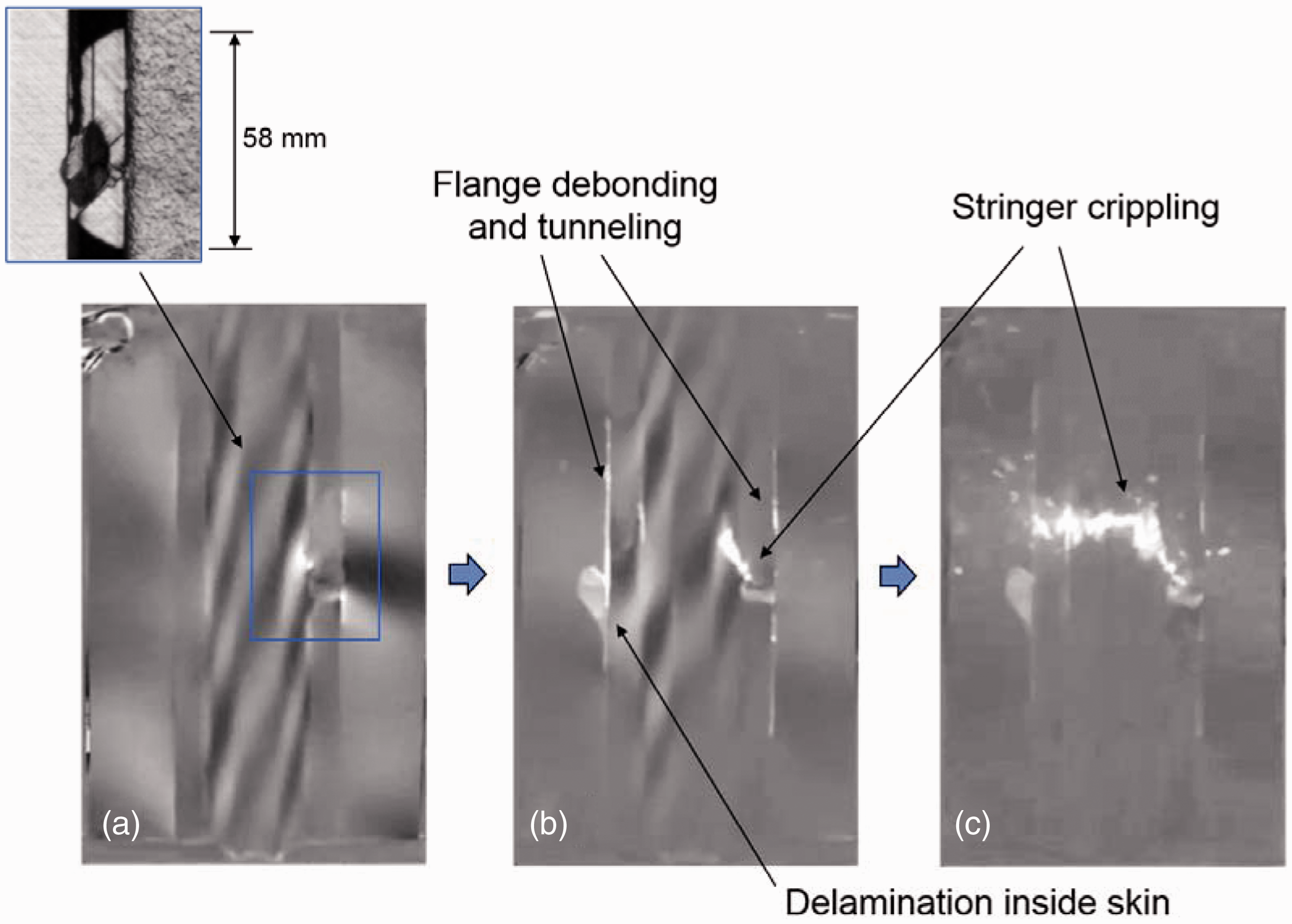
The images in Figure 14(b) and (c) indicate that the collapse of the specimen, which occurs in about 1/60th of a second, consists of debonding of both flanges of the stringer, followed by the crippling failure of the stringer. In addition, a delamination internal to the skin grew in the region of the flange opposite to the initial indentation damage during the final instances of the collapse.
Comparison of fatigue damage propagation
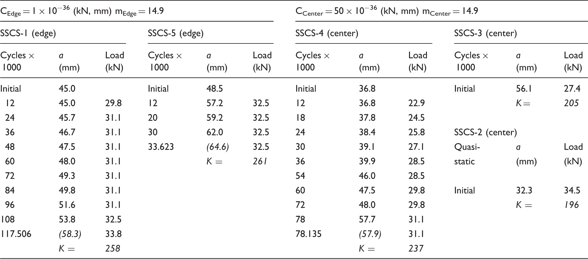
Summary of quasi-static and fatigue test results.
One difficulty in performing an exploratory study in fatigue such as this one is that the cyclic loads required for a practical rate of damage propagation are unknown. To avoid an unnecessarily long test campaign, an ideal rate of fatigue damage propagation would result in a collapse of the specimen in fewer than 100,000 cycles. However, when considering different damage sizes and other variations between specimens, the ranges of loads that cause collapse and those that cause slow fatigue damage propagation can overlap. Therefore, in several instances, the rate of damage propagation was deemed to be too low and the cyclic load was progressively increased. Consequently, it becomes difficult to compare the rate of fatigue damage propagation for specimens with different damage sizes, different loads, and possibly different damage morphologies and structural responses.
To enable some means of comparison, the rate of propagation was assumed to depend on a stress intensity measure, K, according to the Paris Law

The results of the fatigue damage propagation are illustrated in Figure 15, where the experimental results are represented by symbols, and the lines correspond to the damage lengths calculated with the Paris law. Two values of C were determined by curve fitting: one for edge indentation and a different one for center indentation: CEdge = 1 × 10−36 and CCenter = 50 × 10−36. For simplicity, the exponent m = 14.9 was kept the same for both types of indentations.
Damage length as a function of loading cycles for specimens SSCS-1, SSCS-4, and SSCS-5.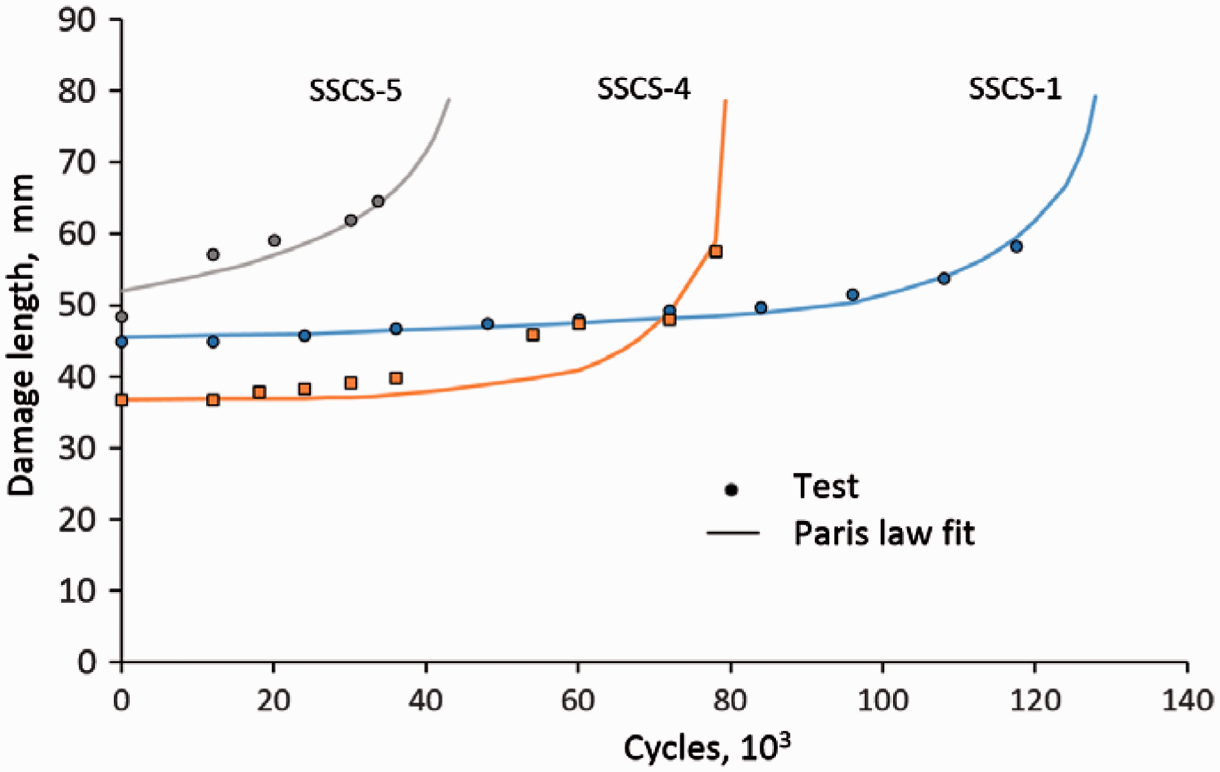
As can be observed in Figure 15, a single set of Paris law parameters provides a good fit to both specimens with edge indentation (SSCS-1 and SSCS-5). This indicates that similar propagation laws characterize the damage growth in both specimens in spite of the differences in initial damage size and cyclic load. It is also apparent that the rate of propagation for center indentation (SSCS-4) is about 50 times higher than for edge indentation, perhaps because center indentation causes more damage toward the highly loaded web/flange corner than edge indentation.
Comparison of collapse loads
It is important to examine the effect of defect size on the collapse load. Indeed, for any damage size, there is a critical load that causes a collapse of a SSC specimen. The collapse load as a function of defect size is shown in Figure 16. In addition to the results from the phase IV test campaign, results from the three previous experimental phases12,14,16 are included. For quasi-static tests, the defect size is the initial defect size, and for fatigue tests, the defect size is the damage length at the moment of collapse. The damage length at the moment of collapse is estimated by adding an incremental extension of the damage length calculated from the Paris Law equations determined above to the last measured damage length.
Effect of defect size on collapse load of SSC specimens.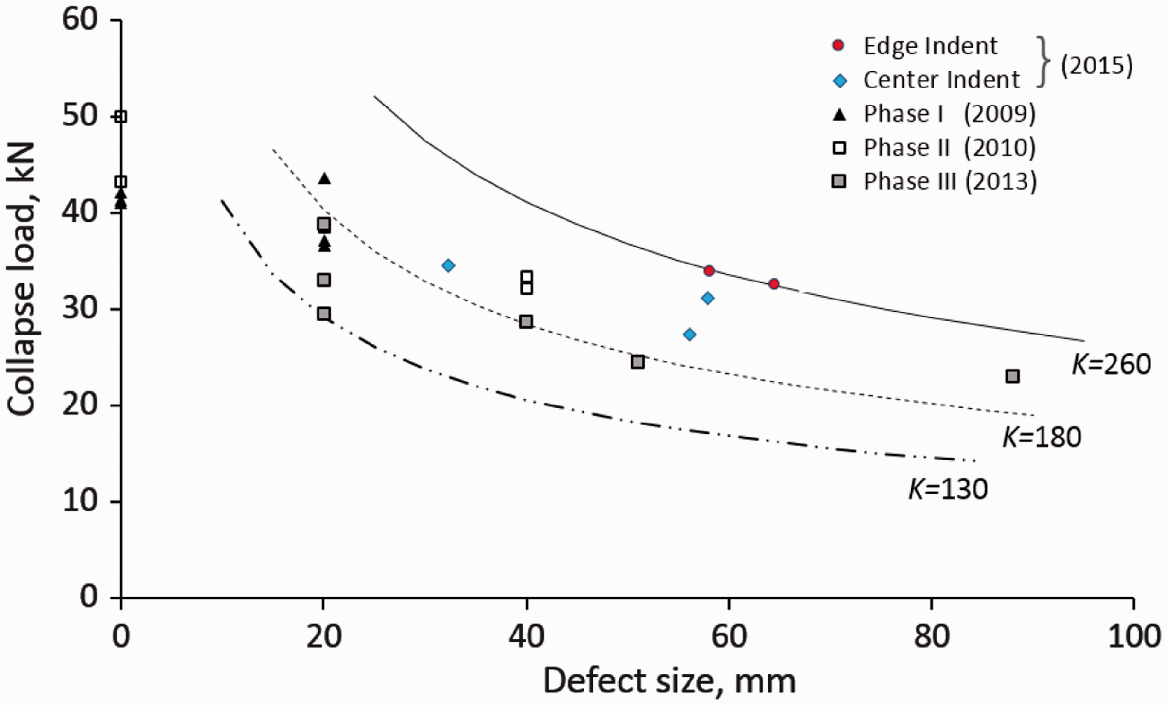
Following the concept used in the previous section, it may be useful to compare the results of different tests according to the stress intensity measure. Using Figure 16, it can be observed that the edge indentation specimens collapsed at approximately K = 260 kN × mm0.5. The center indentation specimens failed within the range 196 ≤ K ≤ 237 kN × mm0.5. It appears that specimens from previous test campaigns failed at lower values of K, which indicates that indentation damage may be less severe than a Teflon insert of the same size. A number of additional contributing factors that deserve the attention of future work, such as the shape of the postbuckling deformation, also contribute to the damage tolerance of a postbuckled panel. Therefore, the proposed classification of the collapse strength of similar specimens according to their stress intensity measure provides a useful means to assess different aspects of the response on the damage tolerance of stiffened structures with defects.
Conclusions
A series of static and fatigue tests were performed on SSC specimens. Five specimens were manufactured with a cocured hat stringer, and an initial defect was induced at the specimen mid-length by indentation of the skin under the stringer flange. The target indentation damage size was selected to be approximately 40 mm, so to be comparable with the size of the rectangular 40 mm-long Teflon inserts used during a previous test campaign.
One of the specimens was tested under quasi-static compressive loading to determine an upper bound for the cyclic loads, while the remaining four specimens were tested by cycling in postbuckling. However, specimen SSCS-3, which was intended for fatigue testing, collapsed during the first loading cycle.
The tests were conducted under controlled conditions and the specimens were monitored throughout the loading to obtain detailed information on deformation response characteristics and damage evolution. Three-dimensional digital image correlation was used to obtain full-field displacement measurements, and in situ passive thermography and UT were used to track damage evolution.
Fatigue tests were conducted in stages so that UT scans of the indented area of the panel could be performed at regular intervals. In addition, passive thermography with an infrared camera was used to monitor the growth of the initial delamination damage while the specimens were being cycled. The real-time information from the thermography was used to determine additional stopping points along the fatigue tests to ensure that critical stages of the damage evolution were recorded with UT scans. Thermography also captured the details of the damage events occurring during the collapse and was therefore useful to evaluate the sequence of the damage, including debonding of the flange, tunneling, delamination in the skin, and stringer crippling.
To enable a comparison between different tests, a procedure was proposed based on the concept of stress intensity measure, which is the product of the applied load and the square root of the damage size. The stress intensity measure provides a means to compare the collapse loads of specimens with different damage types and damage sizes.
The stress intensity measure was also applied in a Paris law to compare the damage propagation rates in specimens loaded with different cyclic loads and different damage sizes. The empirical measures applied are not intended for use as prediction tools for damage tolerance and fatigue life because they do not account for a number of factors such as the location of the damage, the postbuckling deformation, or the shape of the damage. However, the approach does enable a comparison of different tests and the potential identification of effects that influence the fatigue lives and damage tolerance of postbuckled structures with defects.
Footnotes
Acknowledgments
The authors would like to thank the colleagues of the NASA Langley Research Center who contributed to this effort. In particular, Dr Kyong Chan Song for performing the indentation tests, Mr Rufus Sykes for taking the CMM measurements, and Mr George Cowley for operating the laboratory equipment and the UT, Dr Joe Zalameda for performing the thermography, Drs David Dawicke and Nate Gardner for the recording and analysis of the VIC-3D data, and Dr Cheryl Rose for providing the resources and team coordination.
Declaration of Conflicting Interests
The author(s) declared no potential conflicts of interest with respect to the research, authorship, and/or publication of this article.
Funding
The author(s) received no financial support for the research, authorship, and/or publication of this article.