
Abstract
An experimental study has been carried out to investigate the behaviour of co-bonded carbon fibre reinforced plastics joints with a novel design incorporating a through the thickness local reinforcement. Different specimens were manufactured to investigate static and fatigue behaviour, as well as delamination size after impact and damage tolerance characteristics. The mechanical performances of the specimens with local reinforcement, consisting of the insertion of spiked thin metal sheets between co-bonded laminates, were compared with those ones obtained from specimens with purely co-bonded joints. This novel design demonstrated by tests that damage progression under cycling load results significantly delayed by the reinforcements. A significant number of experimental results were obtained that can be used to define preliminary design guidelines.
Keywords
Introduction
Failure predictions for bonded fibre reinforced plastics (FRP) composites have been researched extensively, but the mechanisms are not yet well-understood. Bonded FRP shows different failure modes, and ASTM D5573 identifies seven classes of failure modes
1
:
Adhesive failure, sometimes referred to as interfacial failure: the separation appears to be at the adhesive-adherent interface; Cohesive failure: the separation is within adhesive; Thin-layer cohesive failure, sometimes referred to as interphase failure: the separation is very close to the adhesive-substrate interface; Fibre-tear failure: failure occurs exclusively within the FRP matrix; Light-fibre-tear failure: failure occurs within the FRP substrate, near the surface, characterized by a thin layer of the FRP resin matrix visible on the adhesive; Stock-break failure: break of the FRP substrate outside the adhesively bonded-joint region, often occurring near it; Mixed modes failure: any combination of two or more of the six classes of failure modes defined above.
The failure mode and the ultimate strength load depend strongly on several factors, such as the mechanical properties of adhesives and adherents; the eventual residual stresses; the surface preparation and interaction; the loading condition; and the joint configuration.
Consequently, failure predictions have to consider all these factors, but also different parameters (e.g. surface ply angle, stacking sequence, bond-line thickness), so it becomes difficult to predict failure strength because of its dependence on different bonding methods and parameters.
Fasteners are commonly installed to provide arrest by clamping the laminates together, and are often requested by certification authorities. Multiple fasteners installed in series have been shown to provide significant arrest capability, 2 but increase the weight of the structure and need to create holes that can be critical for crack propagation.
Different 3D reinforcement methods have been studied over the past years to improve the performance and in particular the damage tolerance of bonded joints of carbon fibre reinforced plastics (CFRP), trying to overcome the disadvantages. The 3D reinforcements establish a mechanical link between two adhesive-bonded CFRP structures. A general overview over reinforced and trans-laminar composites can be found in Dickinson et al. 3
Different techniques have been studied and considered, e.g. stitching, tufting and Z-pinning. In stitching and tufting, a needle perforates a fabric preform, inserting a high-tensile-strength yarn made of glass, carbon or aramid. In particular, tufting requires access only on one side of the fabric, since the needle penetrates and retracts through the same pathway. Both the techniques can only be applied to joints made from resin-infused fabric. On the contrary, Z-pins are suitable for pre-preg composite laminates. They can be both thin metallic or composite rods inserted in the through-thickness direction of a laminate during manufacturing. A review of the research into polymer composite laminates reinforced in the through-thickness direction with z-pins is presented in Mouritz. 4
Tong et al. 5 describe the variety of processes used to manufacture 3D reinforced composites as well as the models for predicting failure strength. Great importance is given to the results in terms of performances, such as in-plane mechanical properties, failure mechanism under tension, compression, bending and fatigue loads.
Failure mechanism and evaluation of the energy release rate have been studied for single lap joints stitched and unstitched specimens in Glaessgen et al., 6 observing that the stitches delayed the debonding phenomenon and increased the failure load of two and a half times. An improvement in the failure load and in the damage tolerance has also been noticed with stitched T-joint specimens in Stickler and Ramulu 7 tested under flexure and tension loads.
Freitas et al. 8 investigated the tensile pull-off strength of carbon-epoxy T-shaped joints with z-pin reinforcement made of titanium alloy. The tests results showed that the z-pins were not effective in suppressing the onset of tensile damage in stiffened panels. However, the reinforced joints continued to support an increasing load 2.3 or 2.6 times higher than the failure load for unreinforced joints.
Detailed studies of z-pinned composite bonded joints and the influence of different parameters like z-pins size, volume content and type of loading can be found also in Koh 9 and O’Brien and Krueger, 10 and Chang et al. 11 underlined some of the problems that 3D reinforced structures can face, like broken fibres, fibres kinking or misalignment and resin pockets. All these factors can affect the static and fatigue behaviour of the joints.
Robinson et al. studied the testing of composite laminates reinforced with z-direction pins in mode I, 12 while Stickler et al. investigated the stitched T-joints in bending, 13 and Aymerich the effect of stitching on the static and fatigue performance of co-cured composite single-lap joints. 14 Toral Vazquez et al. conducted a multi-level analysis of z-pinned composite joints. 15
This article reports the results of an experimental study carried out to investigate the behaviour of co-bonded joints on CFRP specimens with a novel design incorporating a through the thickness local reinforcement. Different specimens are manufactured to investigate static and fatigue behaviour, as well as delamination size after impact and damage tolerance characteristics.
Description of the 3-D reinforced composite bonded joints
The laminates are manufactured from T800S/M21 unidirectional carbon/epoxy prepreg tapes from Hexcel, with nominal thickness of 0.12 mm and fibre mass of 134 g/m2 and with nominal ply thickness of 0.193 mm and fibre mass of 198 g/m2. The laminates consist of 16 plies with stacking sequence [45/−45/0/90/−45/45/0/90]S when lower thickness plies are used and of 10 plies with stacking sequence [45/−45/0/90/0]S when thicker thickness plies are used. Photos at the microscope of the two laminates are reported in Figure 1. The changes of the plies were dictated by the fact that Hexcel stopped producing thinner thickness plies. In any case, both laminates result in a thickness of 2 mm and the mechanical properties of the two laminates were compared and were found equivalent.
Photographs at the microscope of a laminate consisting of 16 plies and of a laminate consisting of 10 plies.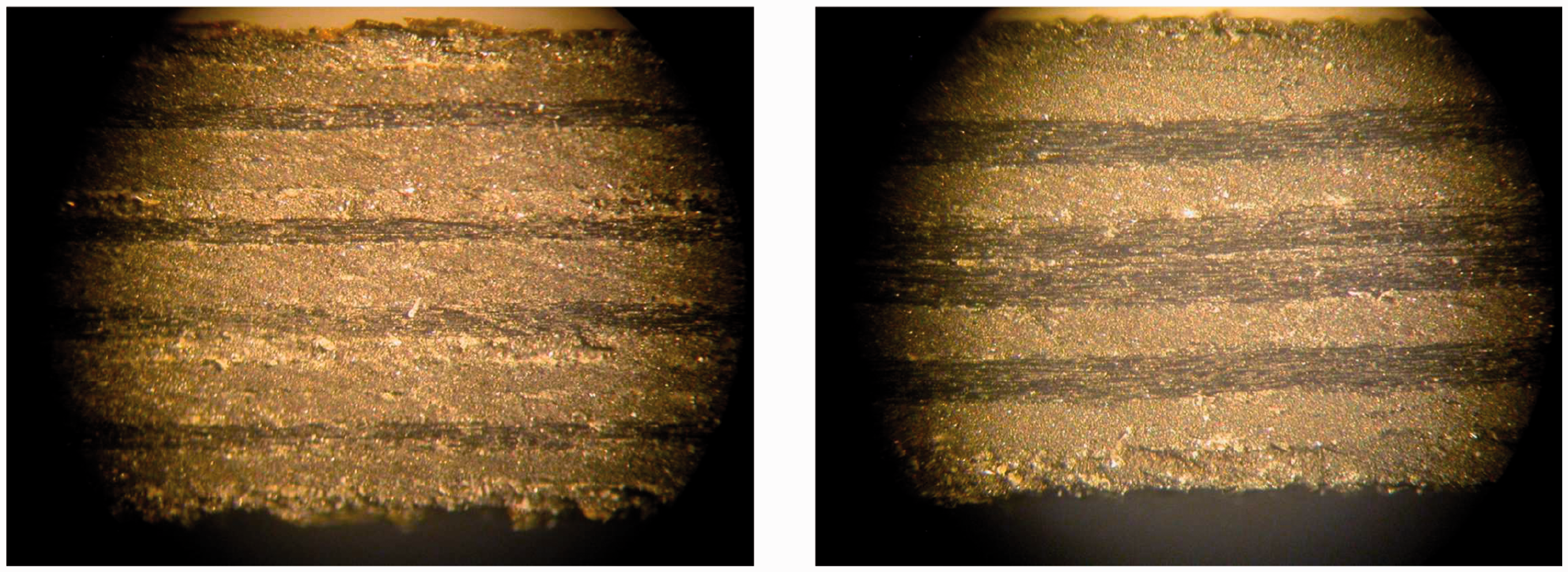
For bonding the laminates, a high shear strength modified epoxy adhesive from Cytec was used. The 3D reinforcements consist of thin spiked metal sheets placed between the co-bonded laminates. This new joint technology is called RHEA (Redundant High-Efficiency Assembly), and is briefly presented in Nogueira et al.16,17 The main concept is to have mechanical interlocking against disbonds and delaminations, and the idea comes from the demand to realize a joint technology that requires minimal design complexity, has low weight, allows fast assembly and avoids point loads.
RHEA consists of spiked metal sheet reinforcement, sketched in Figure 2, that can be produced out of cold formable titanium alloys or stainless steel by metal stamping process with thickness from 0.2 to 0.4 mm. The reinforcements used for the tested specimens here presented are made of stainless steel and are obtained featuring a thickness of 0.2 mm by laser cutting and subsequent bending of the spiked geometry with a special tooling. The advantages are a high volume and low cost manufacturing technique, with robust repeatable process. The only geometric constraint is the pin thickness that is related to the initial foil thickness from which they are obtained. The optimization of the spike geometry and array is currently under investigation.
A sketch and a photograph of Redundant High-Efficiency Assembly (RHEA).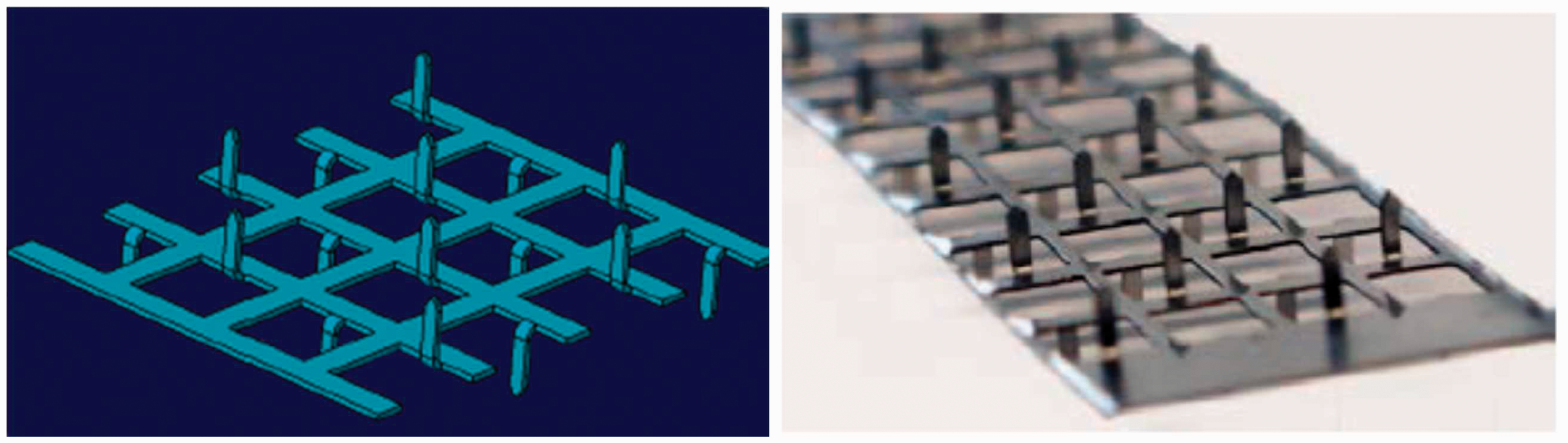
The manufacturing process is schematically shown in Figure 3. At first, the spiked metal sheet reinforcements are introduced into a CFRP prepreg laminate (Step 1). Then, during the curing process, the autoclave pressure and temperature lead to the insertion of the spikes into the prepreg (Step 2). In this way, the fibres are not cut but simply realigned. Once this first curing cycle is completed, the 3D reinforced cured part is joined with another uncured part or with another 3D reinforced cured part through the use of an additional uncured doubler (Step 3). The high shear strength modified epoxy adhesive from Cytec is also added during the joining of the two parts. At the end, the different parts have a sandblasting surface pre-treatment before the last curing process that allows completing the insertion of the spikes through the thickness of the entire laminate (Step 4).
Co-bonding manufacturing process for RHEA joints.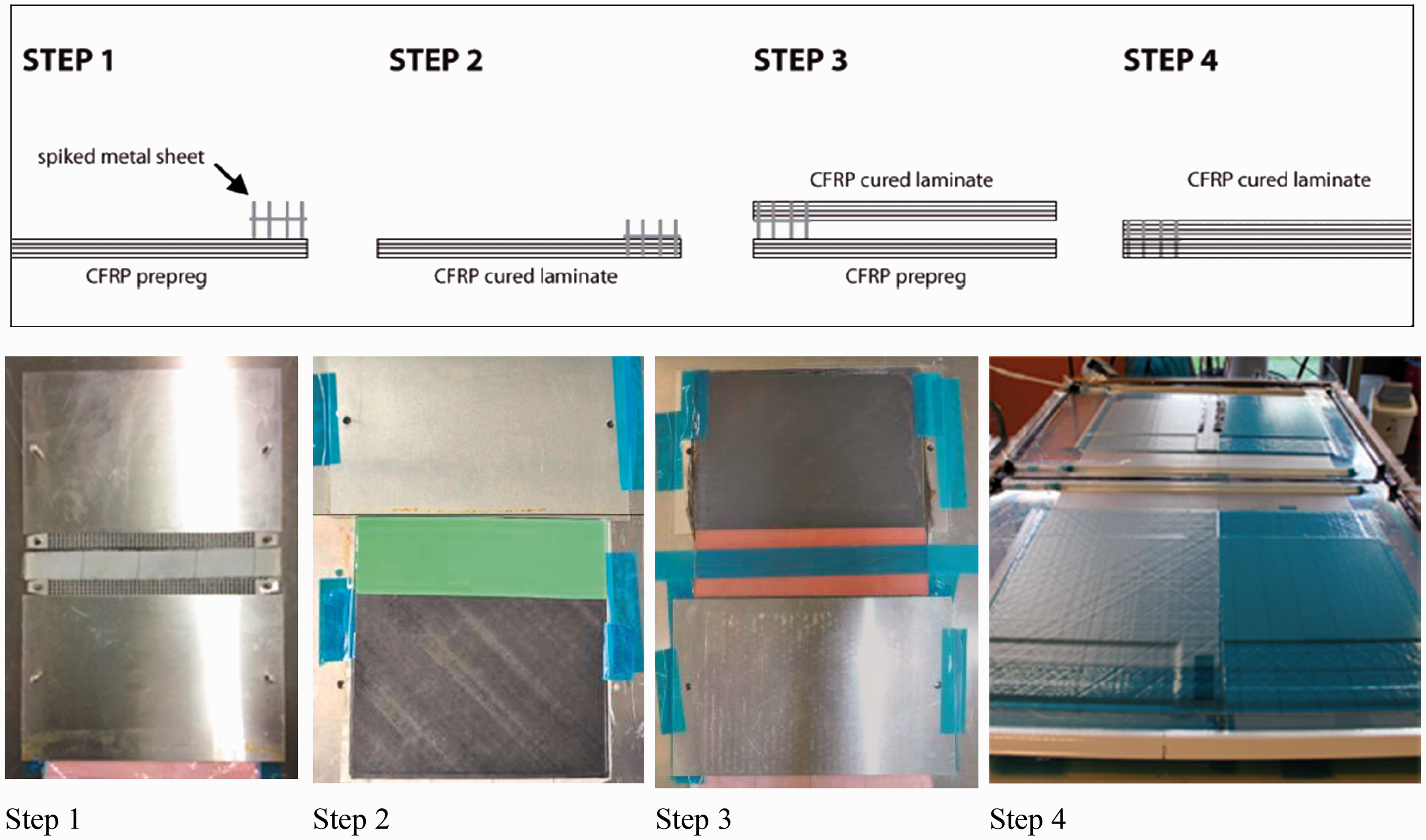
From the first preliminary tests in fatigue done in a previous study,
17
it was found that delamination growth started at early fatigue cycling when metallic reinforcement ended at the joint run out. The presence of metal sheet without pin row at the very first millimetres was not providing benefit for the fatigue initiation. Consequently, it was decided to extend the metallic reinforcement outside the joint run out for a few millimetres (about 2.5 mm), with a one-sided row of spikes, as shown in Figures 4 and 5, because it was found that it delays significantly the damage initiation. The reinforcement was in any case limited to the run out and not extended along the entire bonding line to limit additional weight.
Extension of the metallic reinforcement outside the joint run-out to delay the damage initiation. Photograph of a specimen with RHEA extended outside the joint run-out.
Reference specimens without metallic reinforcement were manufactured at the Department of Aerospace Science and Technology of Politecnico di Milano, using the CFRP material and the adhesive provided by Airbus. The specimens with the metallic reinforcement were manufactured by Airbus Group Innovations (Ottobrunn).
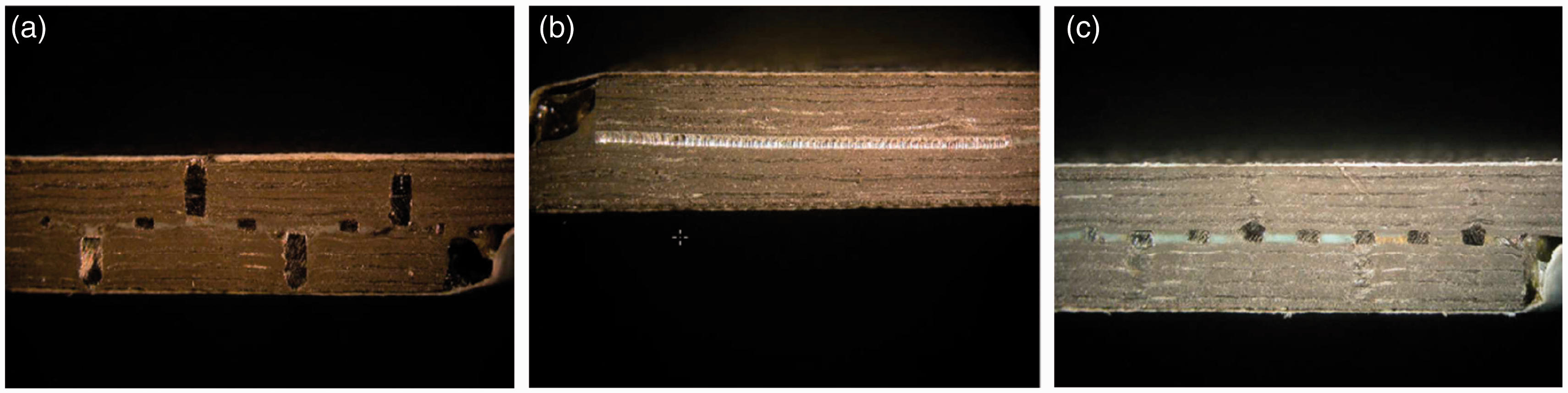
An X-ray scan of a specimen with RHEA is reported in Figure 6, showing a top view of the spiked metal sheet reinforcement. Figure 7 shows some details of the grid through the thickness taken by photos of different specimens at the microscope. Depending on where the metallic reinforcement was cut, different aspects can be seen. In photo A, the pins are visible through the entire thickness with the typical chessboard scheme. Photo B, instead, highlights the constant cross-section in the thickness, while photo C refers to the cross-section near the pins, although they are not completely visible.
X-ray scan of a RHEA specimen. Photographs through the thickness taken at microscope showing different views of RHEA.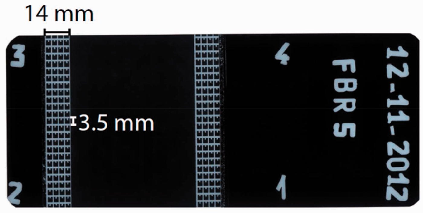
Tests of single lap shear joints
The first type of specimens that was tested consists of unsupported single lap shear joints with overlap distance of 55 mm to represent a load transfer condition similar to the one at typical high load in aircraft structural components. Both specimens without any metallic reinforcements and with RHEA were tested. These types of specimens allow assessment of the static and fatigue behaviour of the new joint design under tensile loading with high peel stresses at bonded line run out.
The single lap shear joints specimen is shown in Figure 8. The metallic spiked reinforcement is present for a width of about 14 mm on each side and extends outside the overlap area for about 2.5 mm.
Single lap shear joint specimen.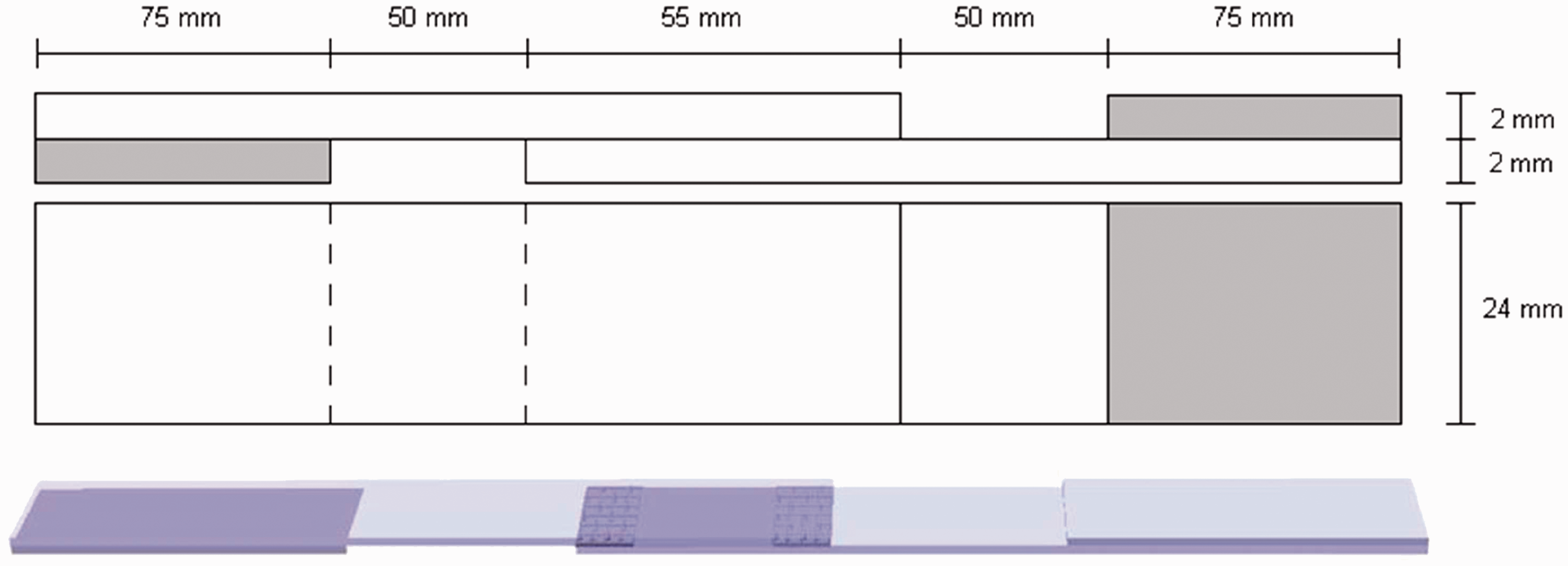
Twelve specimens were manufactured nominally identically without RHEA, and four specimens were manufactured nominally identical with RHEA. All the specimens were co-bonded, so the only difference among the specimens was the presence or not of the reinforcements.
All the tests were performed at the Politecnico di Milano using a MTS testing system 810 TestStar IIs with maximum vertical load equal to 250 kN.
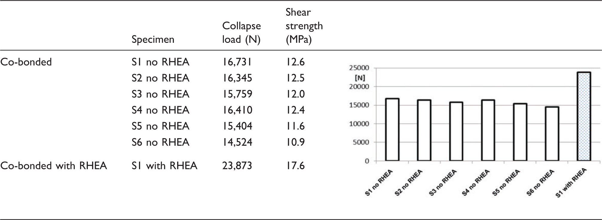
Six specimens without reinforcements and one with reinforcements were statically tested in the same loading conditions. They were named S1, S2… S6 no RHEA, and S1 with RHEA, respectively.
Collapse loads and shear strengths of single lap shear joint specimens without RHEA and with RHEA.
The load-displacement curve measured during the test of specimen S1 with RHEA is compared to the curve of one of the specimens without RHEA (S2 no RHEA) in Figure 9. The specimen with RHEA presents a higher collapse load and also a slightly stiffener behaviour.
Load-displacement curves of specimen S1 with RHEA and specimen S2 no RHEA.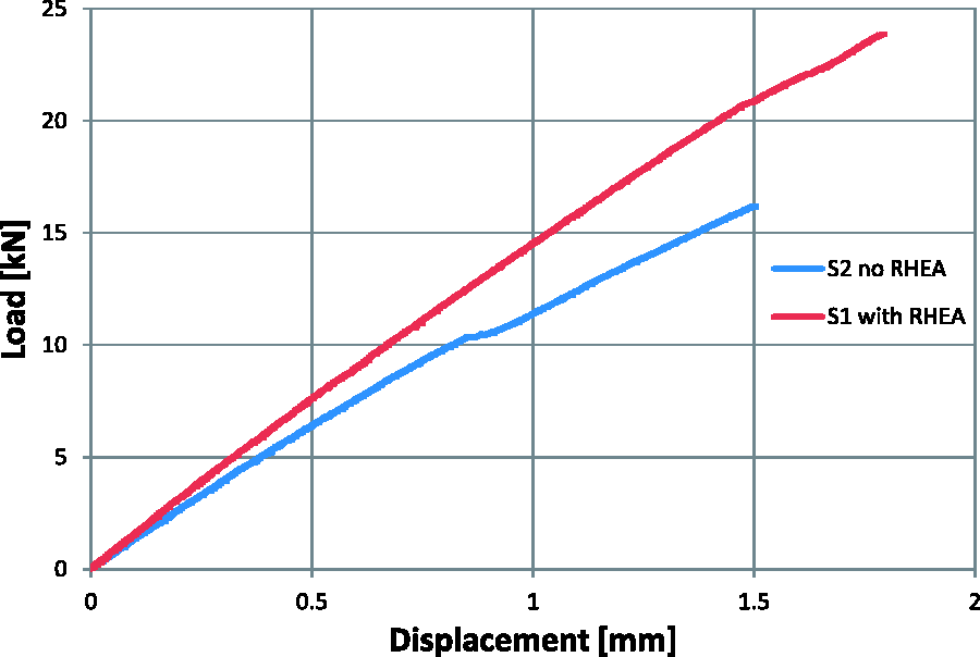
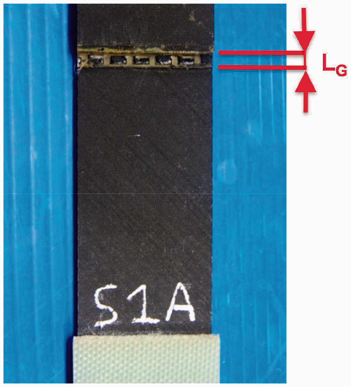
Only a single specimen with RHEA was here tested statically, because more static tests were performed in a previous study.17,18 The previous study on the RHEA joint performance evaluated single lap joints with 0.2 and 0.4 mm metallic reinforcements of steel and titanium. Differences were measured for the different types of reinforcements but in all the cases the ultimate shear strength was always higher than for the specimens purely bonded. The value of 17.6 MPa measured in this study is a little higher than the average value measured in the previous study where a larger number of single lap joints specimens was tested statically. As previously observed, also for the specimen with RHEA here statically tested, the predominant failure mode is fracture Mode II, but there is also a large contribution of fracture Mode II. A photo taken at the microscope of specimen S1 with RHEA after the test is shown in Figure 10.
Photograph of specimen S1 with RHEA after the static test.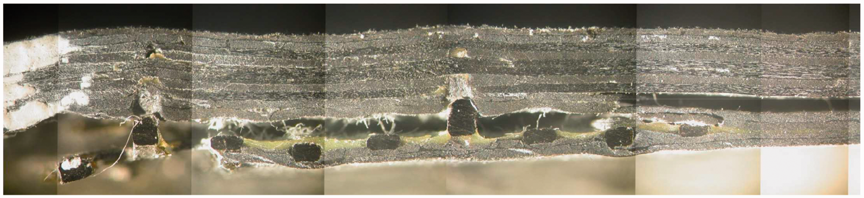
Then, the remaining specimens (six specimens without reinforcements and three specimens with reinforcements) were tested in fatigue. They were named F1, F2… F6 no RHEA, and F1, F2 and F3 with RHEA, respectively. The tests were performed at different level of loads with frequency of 10 Hz.
Summary of fatigue tests on single lap shear joint specimens.
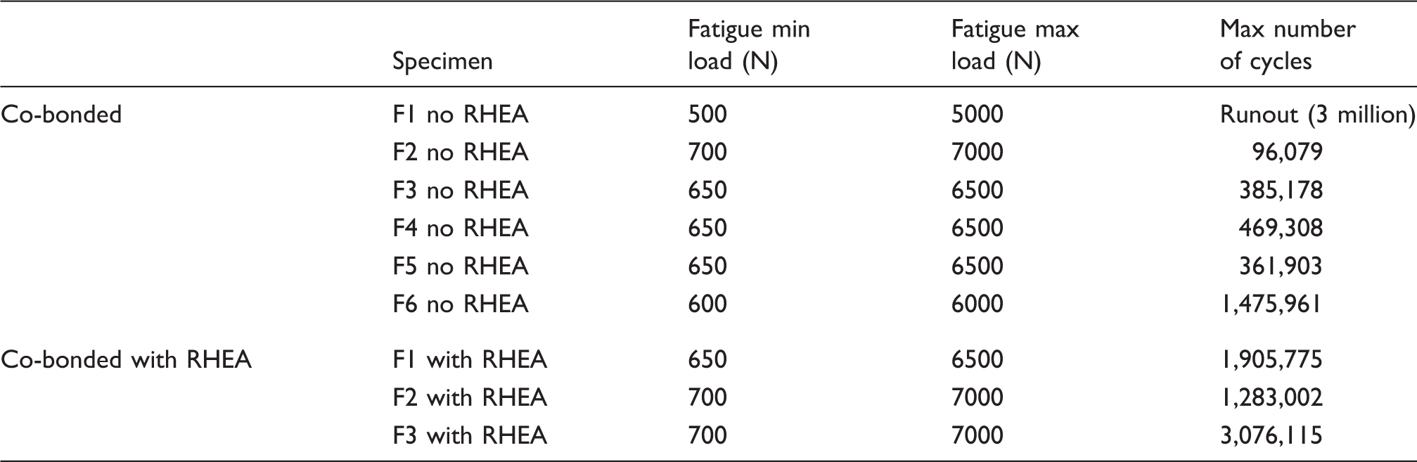
The experimental results show that the fatigue strength as well as the static strength of the reinforced joint (F1–F3 with RHEA) is significantly higher than the co-bonded baseline solution that consist in the same configuration without reinforcements (specimens F1–F6 no RHEA).
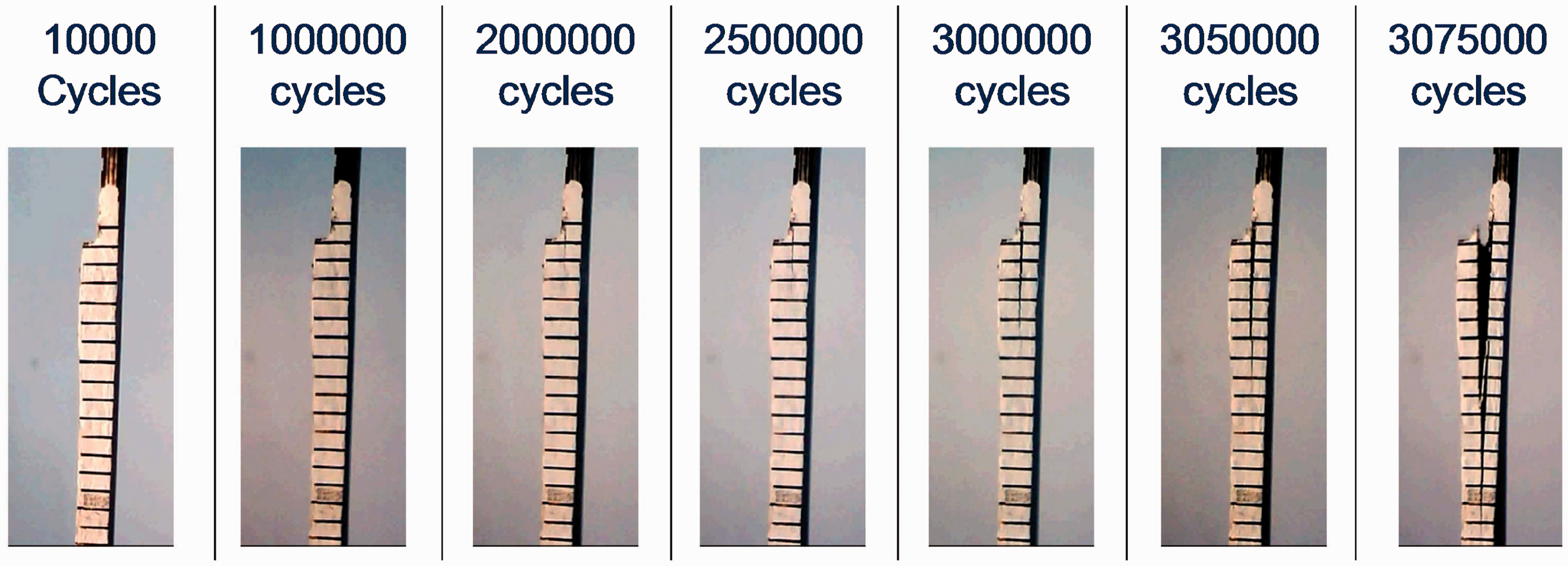
The crack growth was monitored during the tests, and the crack length was measured, using photographs and image analysis, thanks to marks drawn on the specimens. The growth measured during the fatigue test on specimen F3 with RHEA is reported in Figure 11 in function of the number of cycles, and some photos taken on the specimen are shown in Figure 12.
Crack growth measured during the fatigue test on specimen F3 with RHEA. Photographs taken during the fatigue test on specimen F3 with RHEA.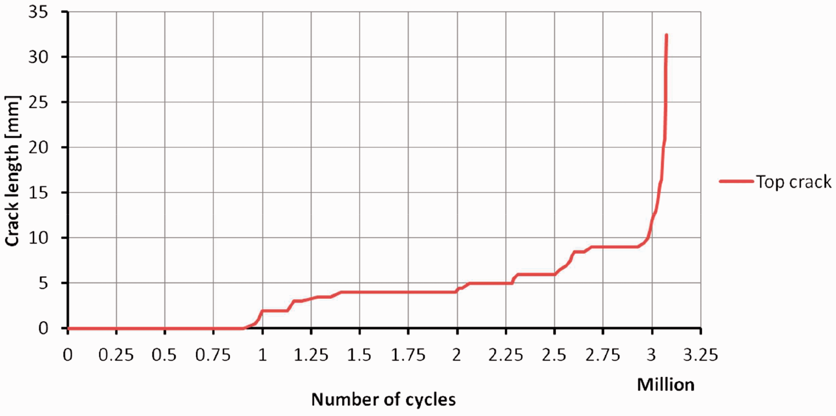
From the results of the tests of single lap shear joints with and without RHEA, it is possible to note that, in general, RHEA provides increased strength and fatigue life. It is mainly due to the resulting combination of adhesive and mechanical load transfers that allows more progressive failure mechanisms.
The failure mode of the single lap shear joints specimens was quite complex and happened at different interfaces. Figure 13 reports some photos of the two parts of specimen F1 with RHEA after the test. In particular, it is possible to see that the metal pins pulled out from one of the two parts. The failure mode is characterised by delamination at different interfaces, fibre breakage and fibre pullouts.
Photographs of the two parts of specimen F1 with RHEA after the fatigue test.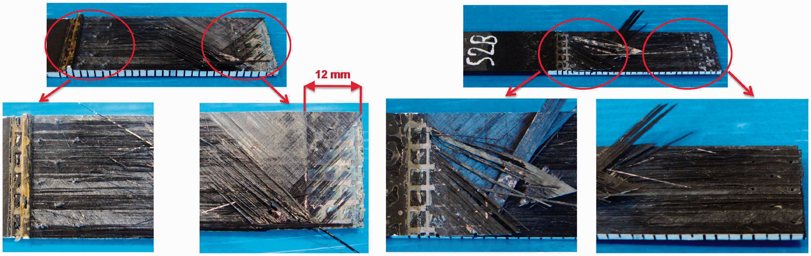
Four-point bending tests of bonded flange specimens
The second type of specimens that were manufactured consists of a bonded flange on a rectangular skin and was tested in a four-point bending setup under static and fatigue loading.
This test configuration was chosen to apply compression load assessing the static and fatigue behaviour of the joints measuring the delamination growth of the reinforced joints and comparing it to that one of the purely co-bonded specimens. The bonded flange specimen is also studied as a preliminary case to investigate a possible future application for stiffened structures, and in particular as reinforcement for stringer run-outs.
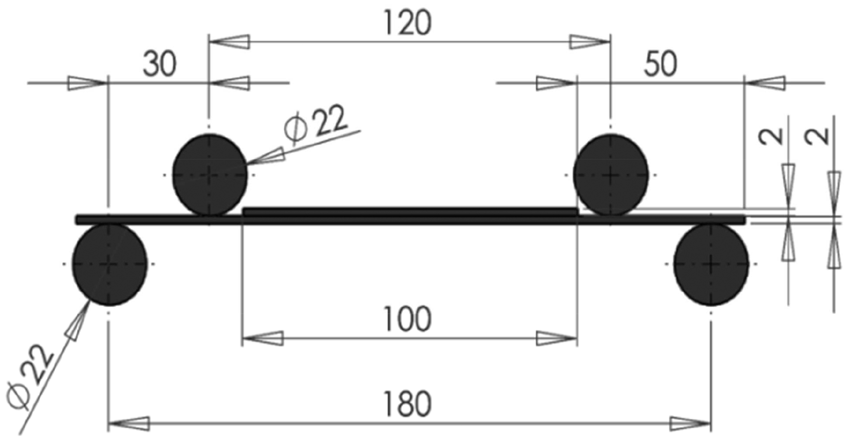
Basically, each specimen consists of two laminates. The first rectangular laminate is 2 mm thick, 100 mm wide and 200 mm long. In the central part, a second laminate was co-bonded using adhesive. The second laminate is 2 mm thick, and both width and length are equal to 100 mm. The dimensions of the specimens are shown in Figure 14 together with the photo of one of them, while the set-up of the tests is sketched in Figure 15.
19
Geometry of bonded flange specimens and photograph of one of the specimens. Set-up for four-point bending tests.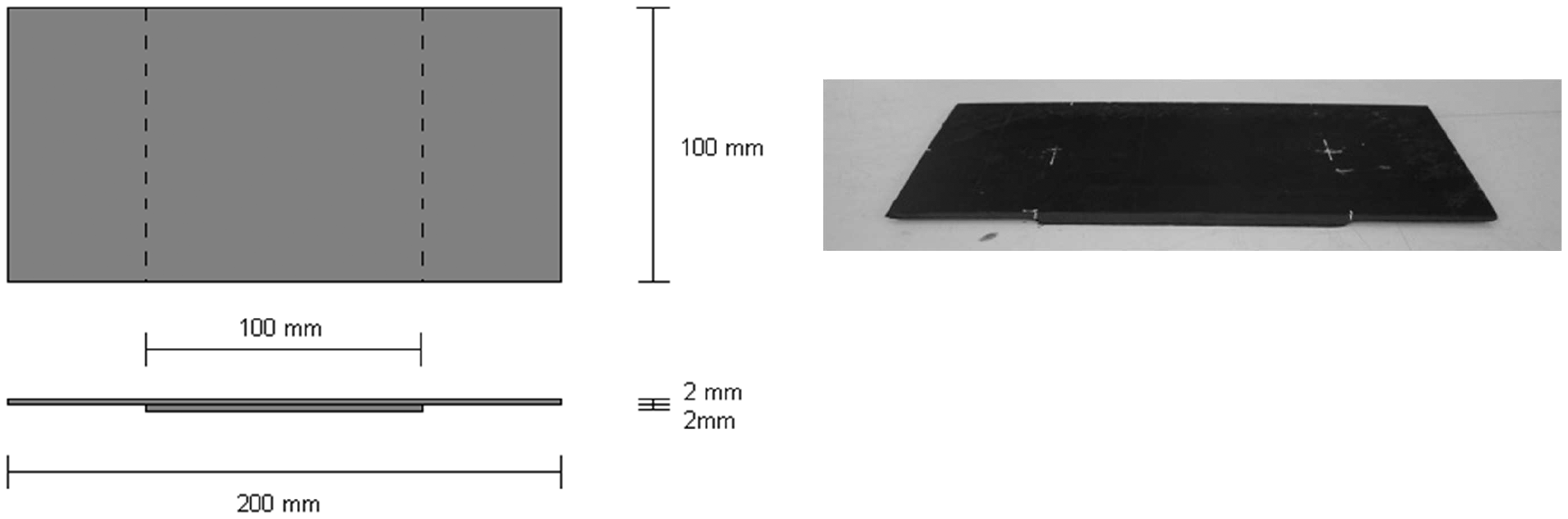
In order to study the influence of an embedded defect at the bonding layer, specimens with a 7 mm Teflon insert at the adhesive level in one side of the specimens were also manufactured. The position of the Teflon insert is shown in Figure 16. The Teflon insert simulates a manufacturing defect during the bonding, and the specimens with Teflon inserts were studied to understand the damage tolerance characteristics in four-point bending conditions, considering both purely co-bonded flange specimens and co-bonded flange specimens with reinforcements.
Position of the Teflon insert.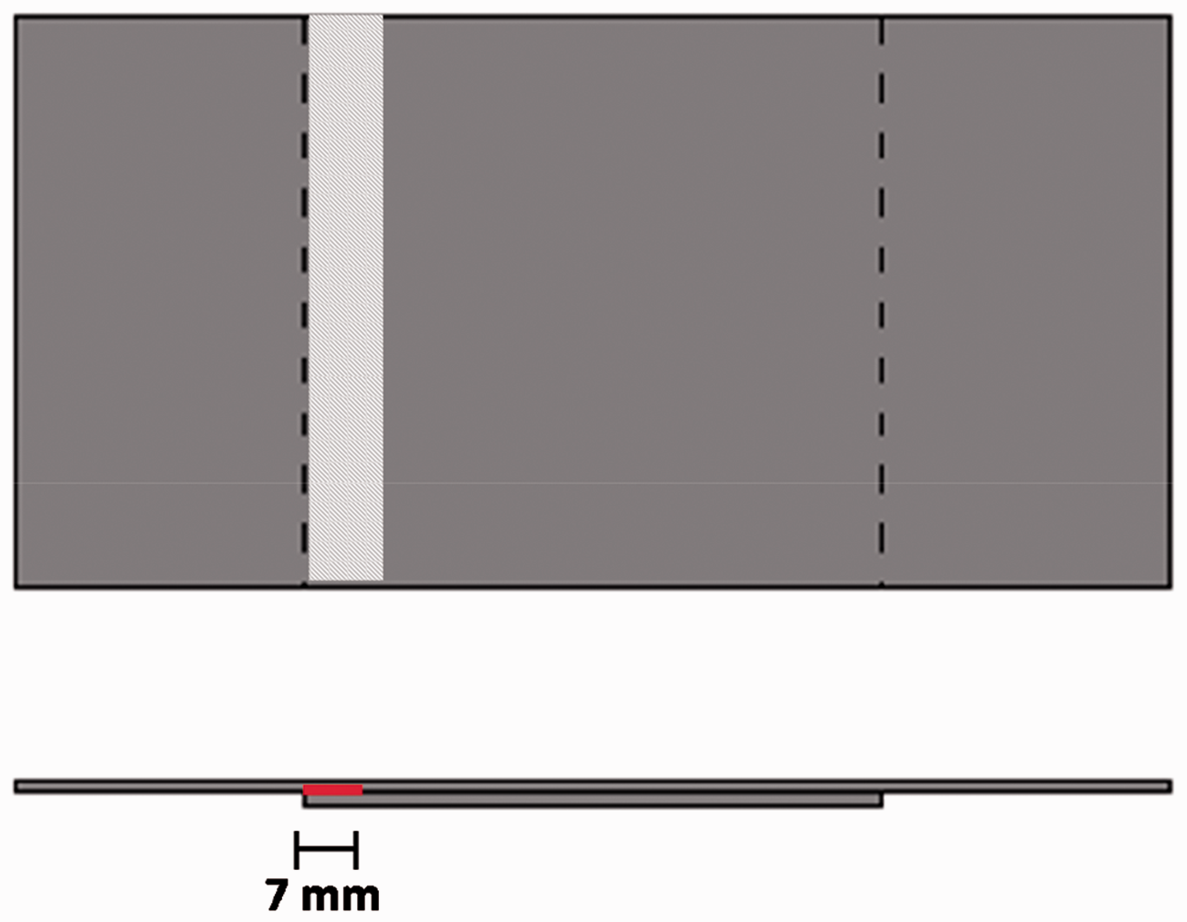
The terms B and T were chosen to describe co-bonded specimens without and with Teflon insert, respectively. Six nominally identical B specimens and six nominally identical T specimens were manufactured.
In the specimens with RHEA, the reinforcements were placed for about 14 mm along the edges of the flange, where the highest shear stresses occur and the damage is more likely to develop. Twelve RHEA specimens were manufactured. Nine nominally identical specimens were provided without Teflon insert, and they are called FBR specimens, while three nominally identical specimens were provided with 7 mm Teflon insert, and they are called FBRK specimens.
A few static tests were performed to get the baseline behaviour. Specimen B1, without reinforcements and without Teflon insert, and specimen T1, without reinforcements and with Teflon insert, were tested in static conditions. Specimen T1 collapsed quite early. Consequently, it was decided to test statically also specimen T3.
Then, fatigue tests were performed on all the remaining specimens considering different load levels up to 50% of the ultimate static load. For some load levels, the tests were repeated on nominally identical specimens. All the fatigue tests were performed at R-ratio of 0.1 and frequency of 2 Hz. A grid was drawn on the specimens thickness to increase the visibility of the damage growth during the cycling.
The influence of the type of specimen and load level was investigated, observing a correlation between the damage growth rate and the load level that depends on the different configurations.
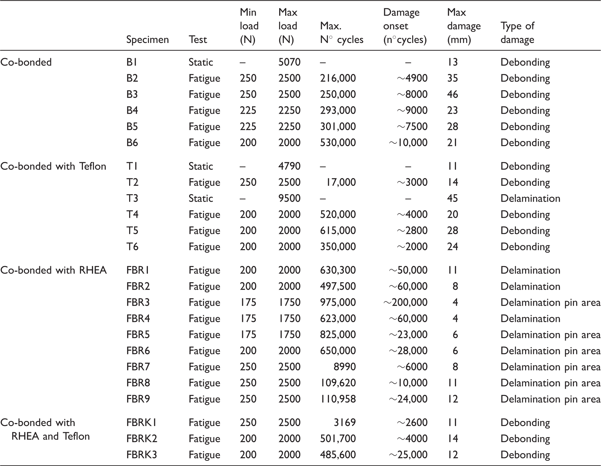
Summary of static and fatigue four-point bending tests on co-bonded and RHEA specimens.
During the tests, the cracks could initiate and grow on the right side and on the left side of the specimen, both on the front and on the back. Consequently, all four possible areas were kept under observation during the tests. The crack length was measured, using photographs and image analysis, in all four areas thanks to the marks drawn on the specimens. For each specimen, the most critical growth was taken into account, and is reported in the tables and graphs.
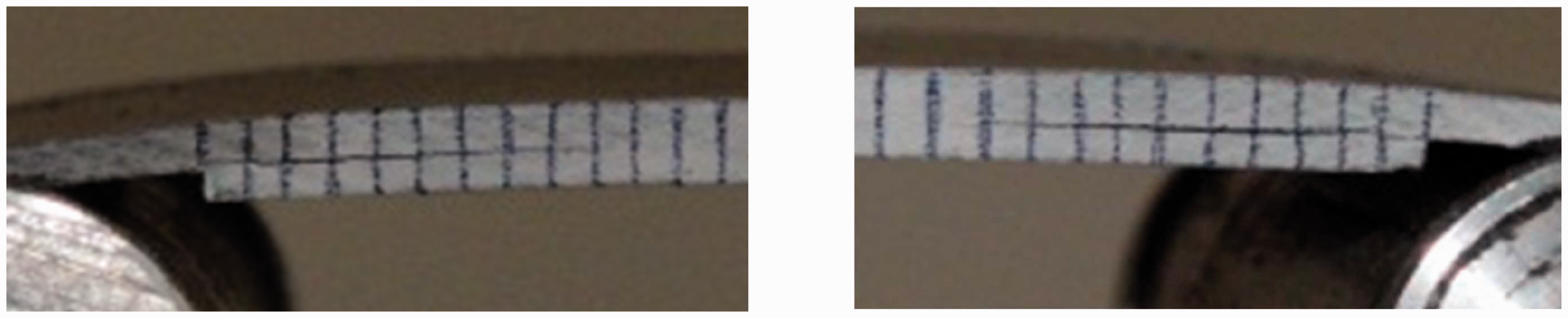
The debonding growth is shown, as an example, in Figure 17 for specimen B6. Specimen B6 was tested in fatigue with maximum load equal to 2000 N. In specimen B6, a pure debonding was observed, without any delamination between the plies, as can be observed in the zoom images of the debonding areas in Figure 18.
Debonding growth on co-bonded specimen B6. Zoom images of the debonding area of the co-bonded specimen B6.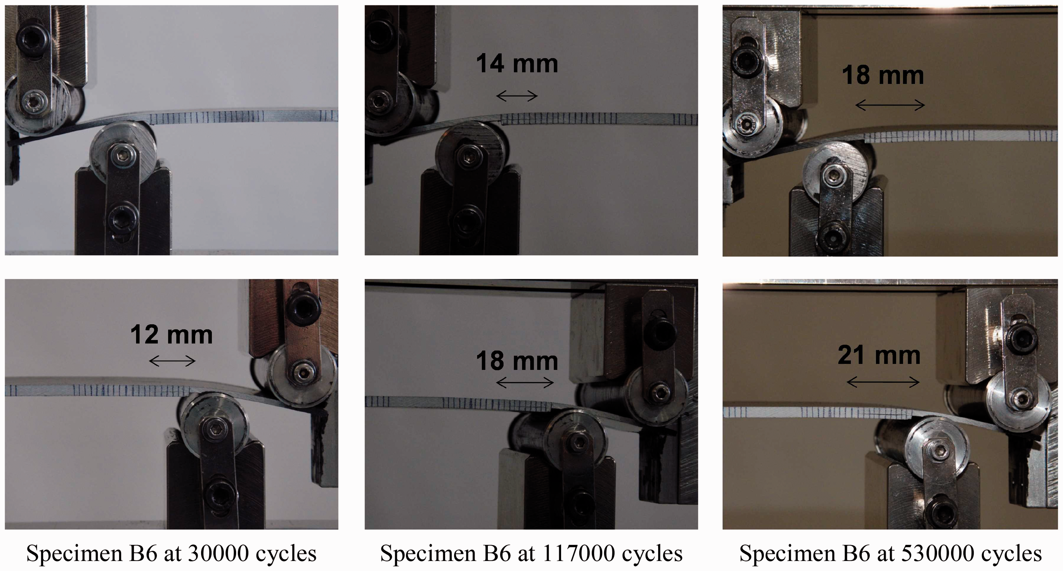
A different behaviour was observed, for example, for specimen FBRK3, a co-bonded specimen with RHEA and Teflon tested in fatigue with maximum load equal to 2000 N, where both debonding and delamination were present on the two different sides of the specimen, as reported in Figure 19, that shows the damage growth.
Debonding and delamination growth on reinforced specimen FBRK3.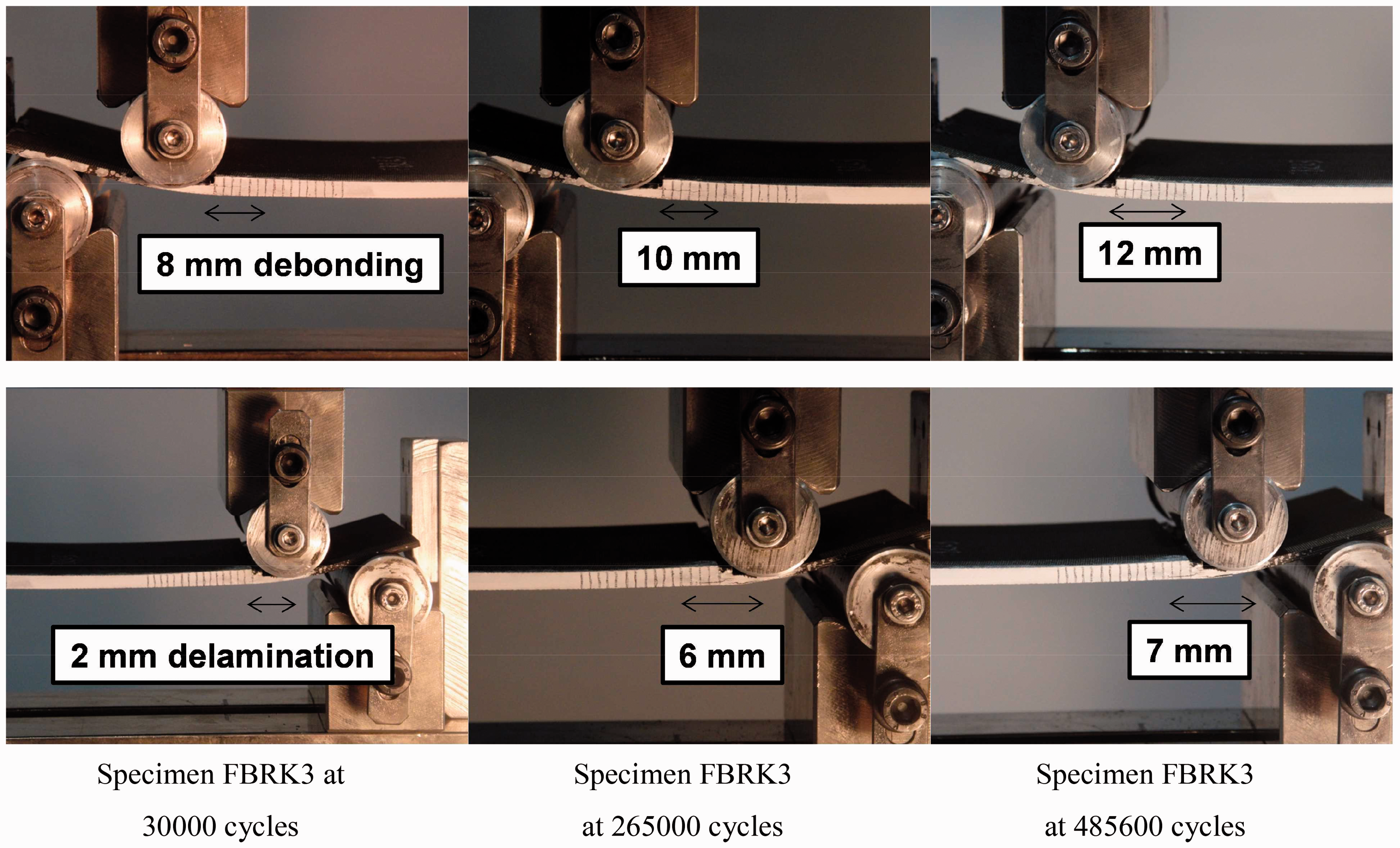
A resin pocket in front of the bonded layer was observed in some specimens. Initial matrix cracks were noticed in these specimens near the resin pocket. They initiated further matrix cracks in lower plies. A detail of this type of damage is shown in Figure 20 for specimen FBR1 with RHEA.
Details of initial damage in specimen FBR1.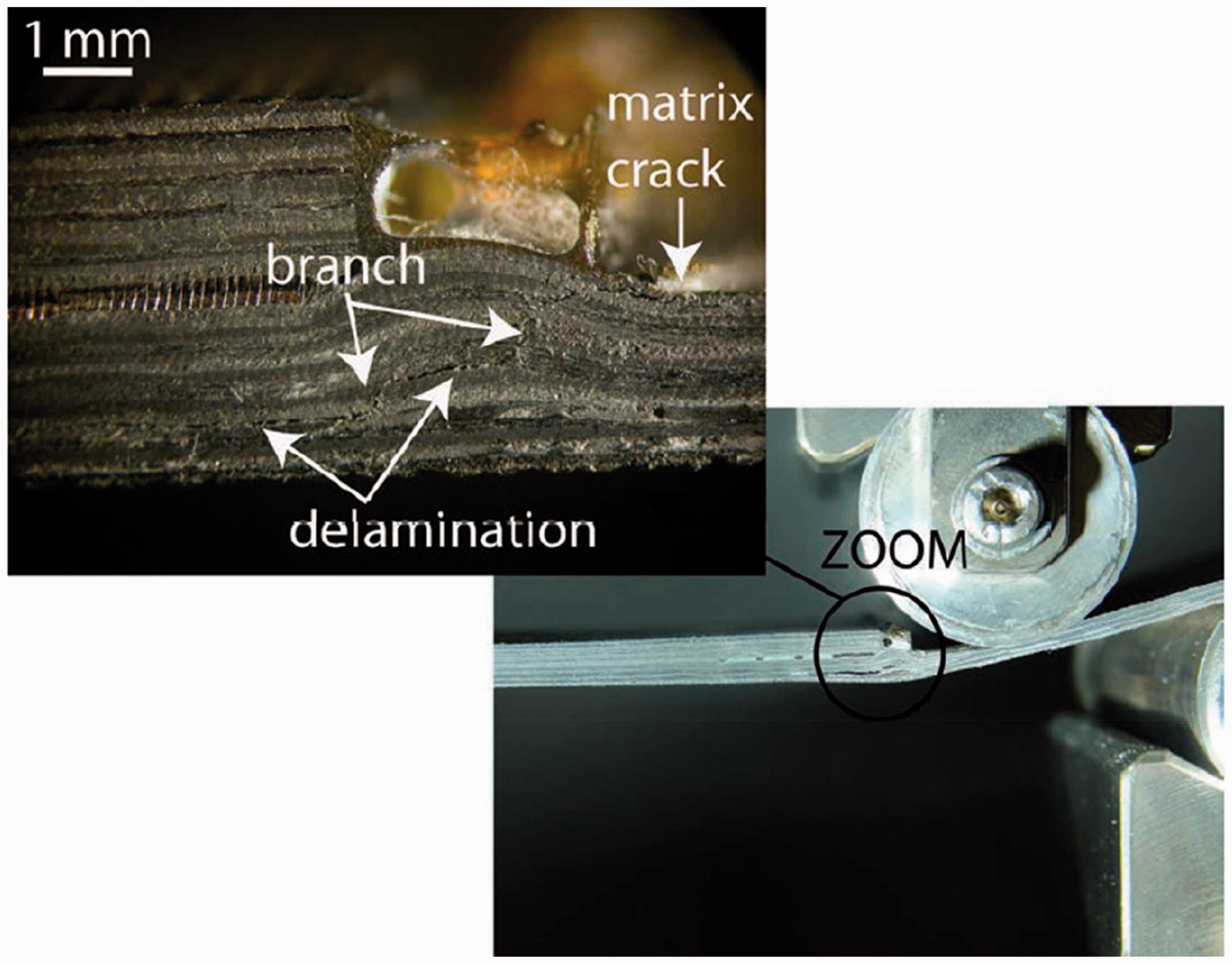
Damage growth for all specimens tested between 200 and 2000 N with Teflon insert, both T and RHEA configurations, are shown in Figure 21. Specimen B6 (completely co-bonded specimen) is taken as baseline specimen, as it was also tested within the same loading range.
Comparison of crack length growth of co-bonded specimens with Teflon (without and with RHEA) with baseline configuration.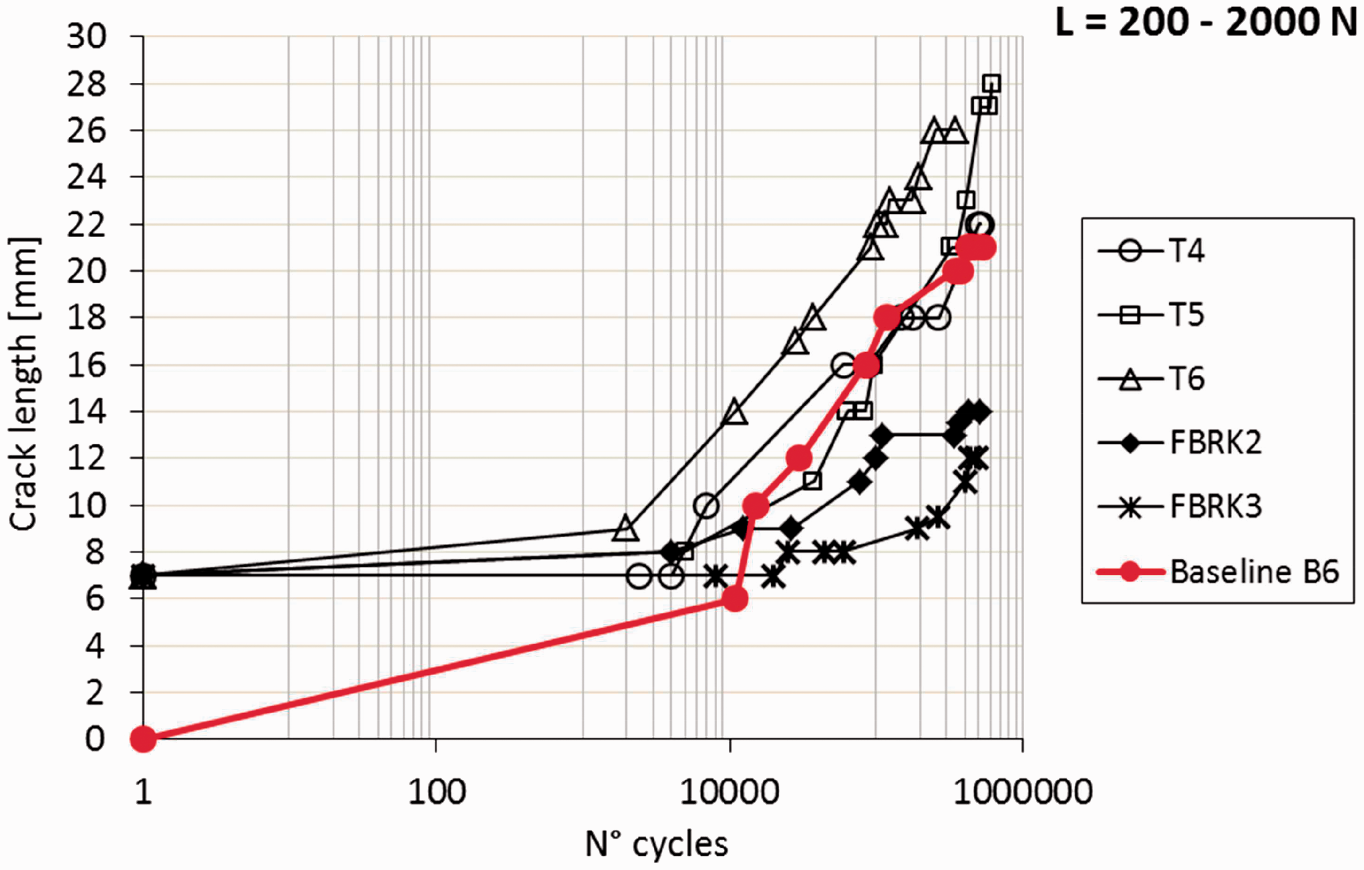
Comparing the typical behaviour of the FBRK specimens to that one of the T specimens, it is observed that in both sets of specimens, the damage started to propagate at the Teflon side, but different damage modes followed for the two sets. Debonding on the opposite side is observed for T specimens, while it is not noticed for the FBRK set, which is characterized by delaminations at a higher number of cycles.
The debonding growth in the FBRK specimens is more controlled and the maximum debonding lengths is equal to 12–14 mm. For low number of cycles the debonding length for the different specimens is comparable, then for the high number of cycles the debonding length measured for both FBRK specimens is shorter than the one of T specimens at the same number of cycles. Besides, the debonding rate does not increase rapidly. In particular, it is interesting to notice that, at the end of the test, the debonding reaches about the length of the RHEA insert at the interface and does not show the steep behaviour typical of the co-bonded set.
The damage growth of two RHEA specimens tested between 250 and 2500 N (FBR8 and FBR9) are examined in Figure 22 taking specimen B3 as baseline (B3 is a co-bonded specimen tested within the same loading range). Also for this load level, it is possible to see that the damage growth is quite limited compared to the baseline configuration, that, after about 10,000 cycles, shows a remarkable and controlled growth. For specimen B3, the crack length refers to debonding of the flange, while no debonding was recorded for the RHEA specimens. The critical length refers to interlaminar damage, developed more or less in the pin area, in the skin laminate. This phenomenon can be due to the fact that the combination of adhesive and mechanical load allows a more progressive transfer in the area of the joints, and consequently the damage develops before in the skin laminate.
Comparison of crack length growth of co-bonded specimens with RHEA with baseline configuration.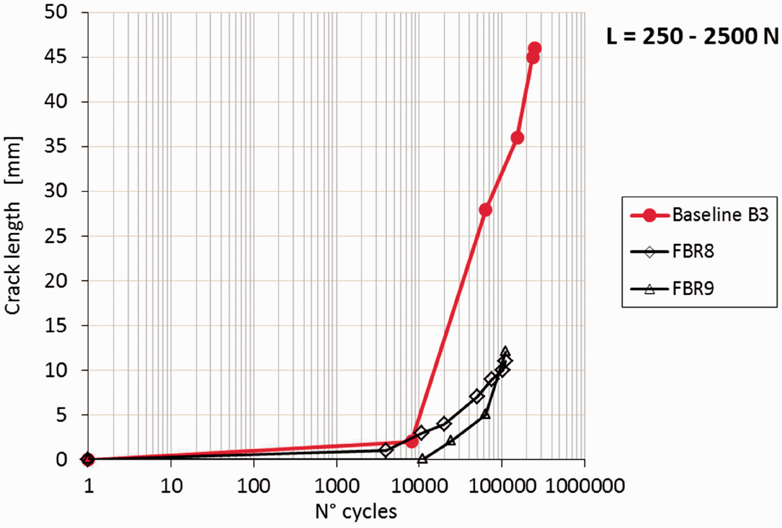
The damage onset for RHEA specimens without Teflon insert tested between 200 and 2000 N is represented in Figure 23 together with the baseline specimen B6. The same figure reports also the damage onset for the Teflon insert specimens, both co-bonded specimens and RHEA specimens, tested between 200 and 2000 N, compared with the baseline specimen B6.
Damage onset for RHEA specimens without Teflon insert and damage onset for Teflon insert specimens, both co-bonded specimens and RHEA specimens, tested between 200 and 2000 N, always compared with baseline specimen B6.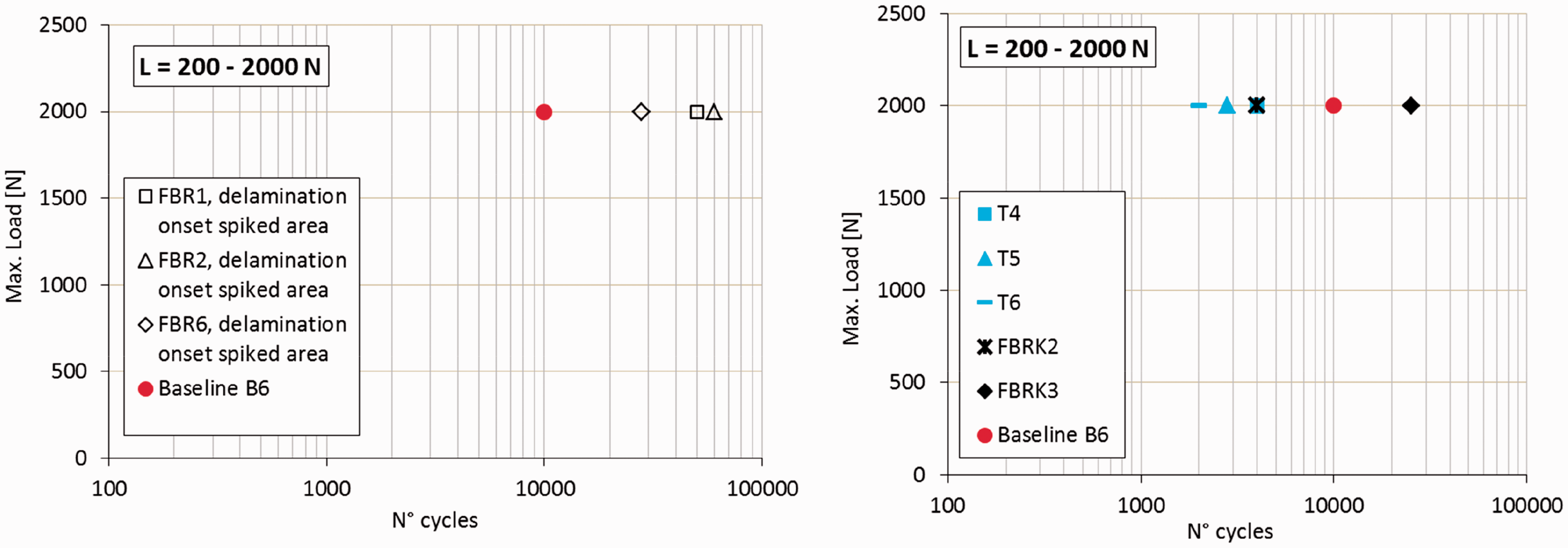
It is possible to note that for the specimens without Teflon inserts the damage onset of the baseline happens significantly before that one of the specimens with RHEA. In the case of specimens with Teflon, the damage onset of the baseline specimen happens to be within the same range of cycles as for the RHEA specimens.
In order to better appreciate the statistical scatter, the damage onsets for RHEA specimens without Teflon insert tested between 175 and 1750 N and between 250 and 2500 N, respectively, are represented in Figure 24. For the tests between 250 and 2500 N, the data are compared with the baseline specimen B3.
Damage onset for RHEA specimens without Teflon insert, tested between 175 and 1750 N and between 250 and 2500 N, respectively.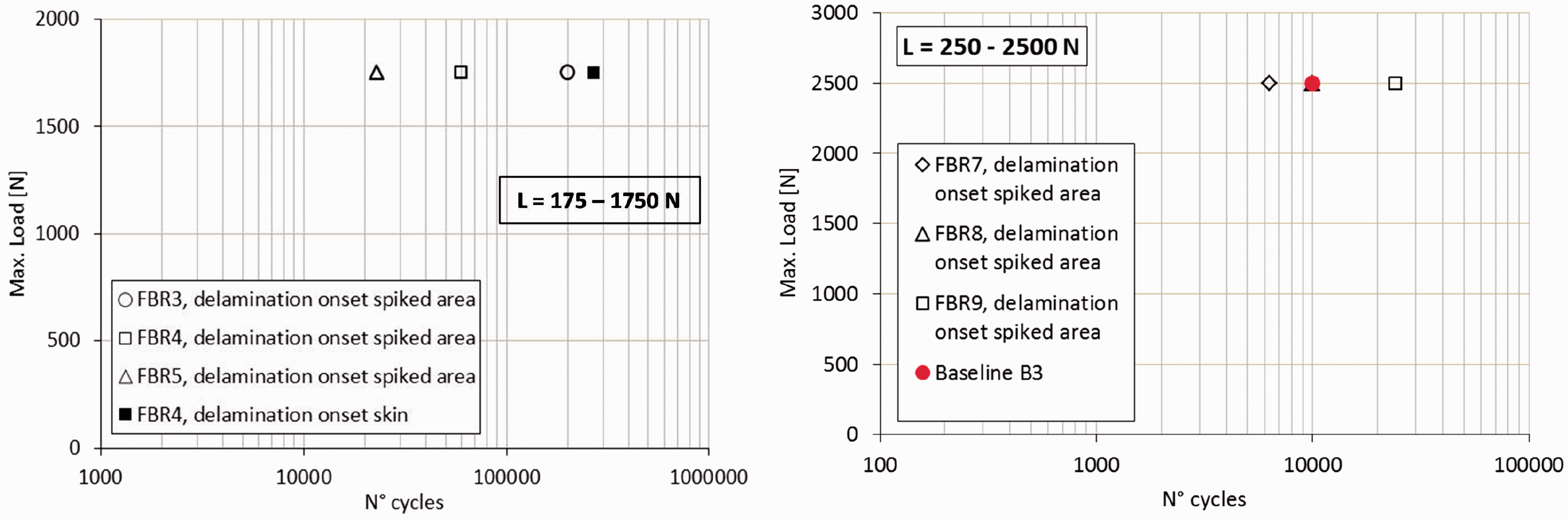
The damage progression under cycling load results significantly delayed by the RHEA reinforcement, especially for the lower load conditions, enhancing the damage tolerance of the joint. In particular, the through thickness metallic pins allow bridging mechanisms of the load, as they provide a secondary load path. It results in crack growth rates lower than co-bonded solutions by an order of magnitude even under compressive loading fatigue.
Low-energy impact tests
The test study was completed with low-energy impact tests. The bonded flange specimens were impacted comparing the purely co-bonded joints with the reinforced ones. Impact damages were introduced at the bond line joint run out impacting the skin side by means of a drop-weight test machine.
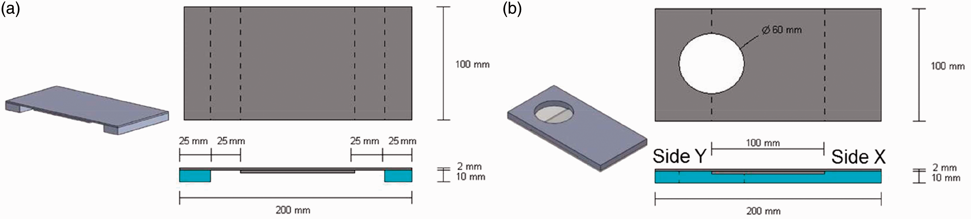
The impactor had a tip diameter of 25 mm and a mass of 1.022 kg. Rebound hits were prevented by sliding a rigid plate between the impactor and the specimen, after the impactor had hit the specimen surface. Two symmetrical locations on the top of the skin laminate were chosen to be impacted for each specimen, as shown in Figure 25. Three different boundary configurations were tested. In particular, two different supports were designed and manufactured. The first one allowed conducting simply supported tests both on side X and on side Y, while the second one allowed conducting fully supported tests on side X and fully supported tests with a hole on side Y. The supports for the different boundary conditions are illustrated in Figure 26.
Impact locations of the low-energy impact test. Boundary conditions used for impact tests: (a) simply supported; (b) fully supported on side X and fully supported with a hole on side Y.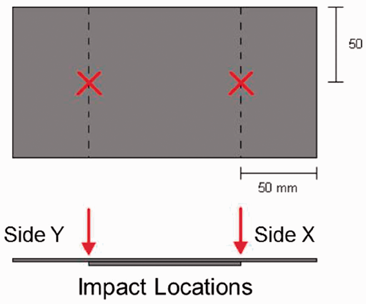
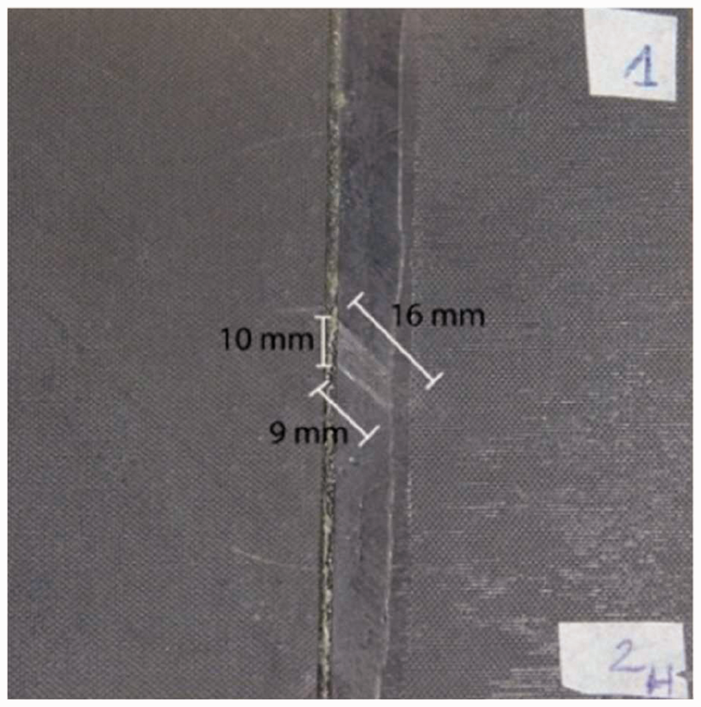
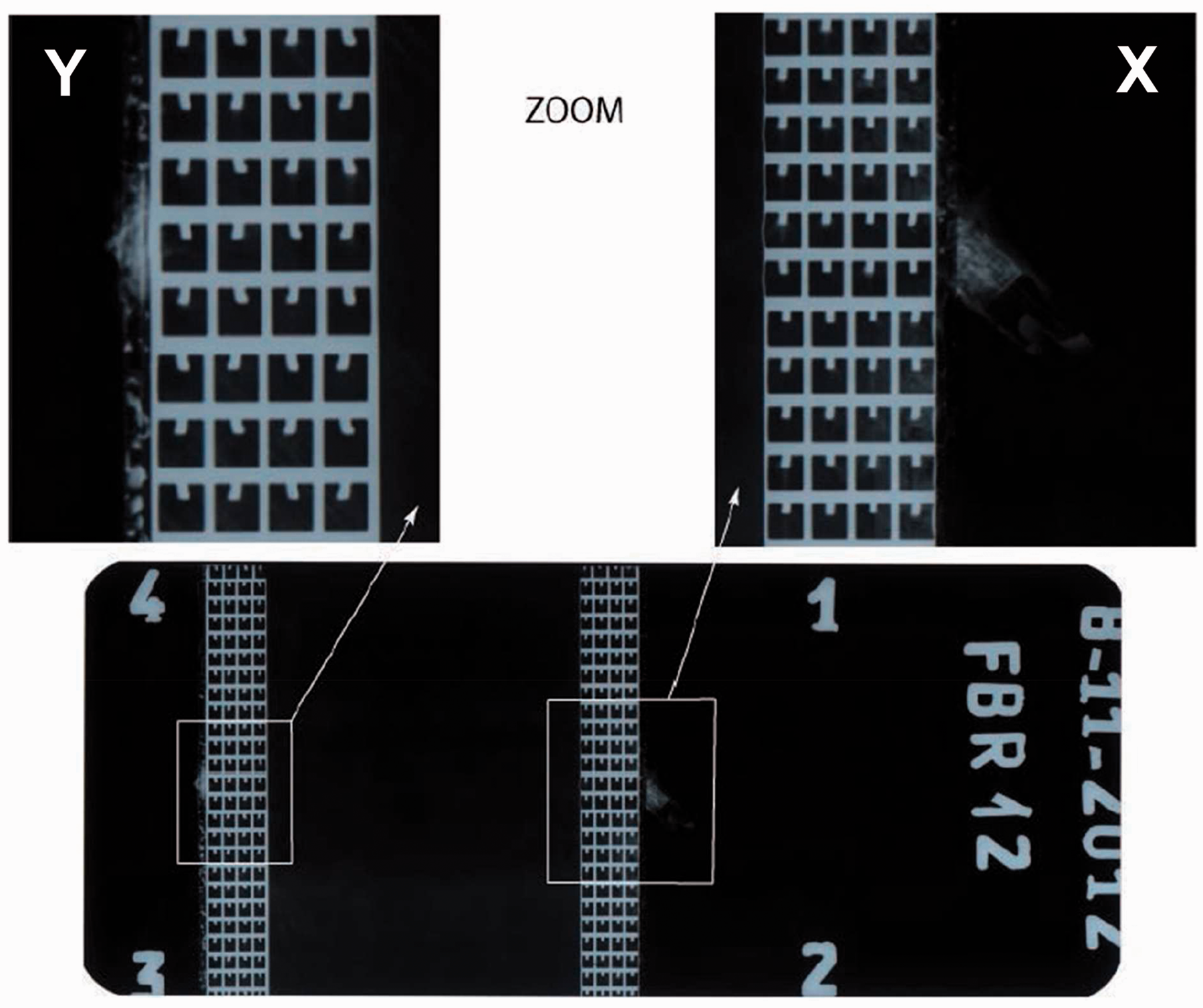
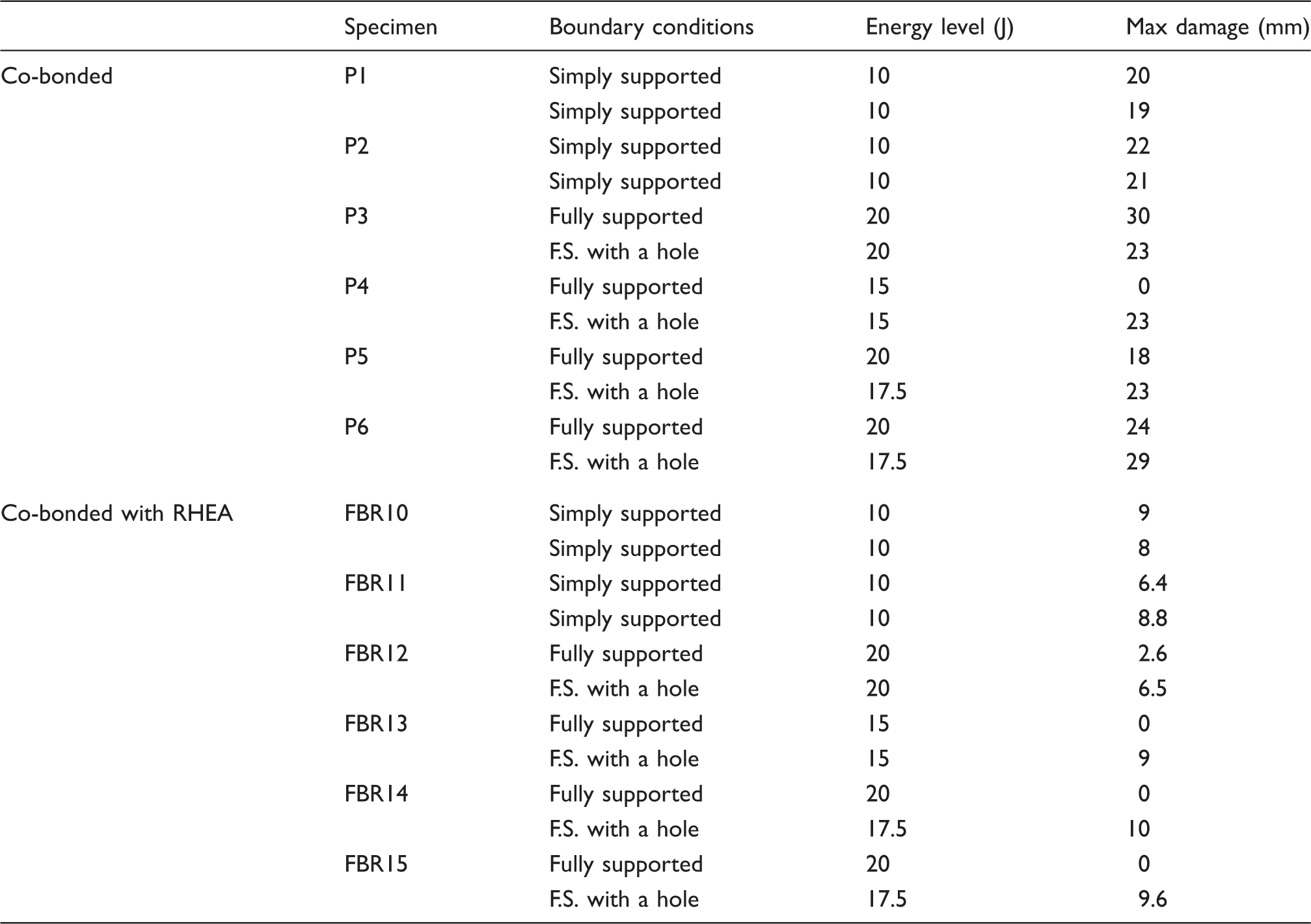
The extent of the damage caused by the impact event was evaluated by visual inspection and by X-ray techniques. Example of X-ray scans of the baseline specimens are reported in Figure 27. In some cases, at the high energy level, it was possible to notice also fibre breakage, as shown in Figure 28. Figure 29 reports the X-ray scans of one of the specimens with RHEA at the energy level of 20 J for two different boundary conditions. The main results of the impact tests on the co-bonded and RHEA specimens are summarized in Table 4. The terms P and FBR are chosen to describe co-bonded specimens and RHEA specimens, respectively. Six P specimens and six FBR specimens were tested.
X-ray scan of baseline specimens: simply supported at 10 J and fully supported with hole at 20 J. Fibre breakage obtained in one of the specimens. X-ray scan of specimen FBR12 after impacts at 20 J: fully supported on X-side and fully supported with hole on Y-side. Summary of impact tests performed on co-bonded and RHEA specimens.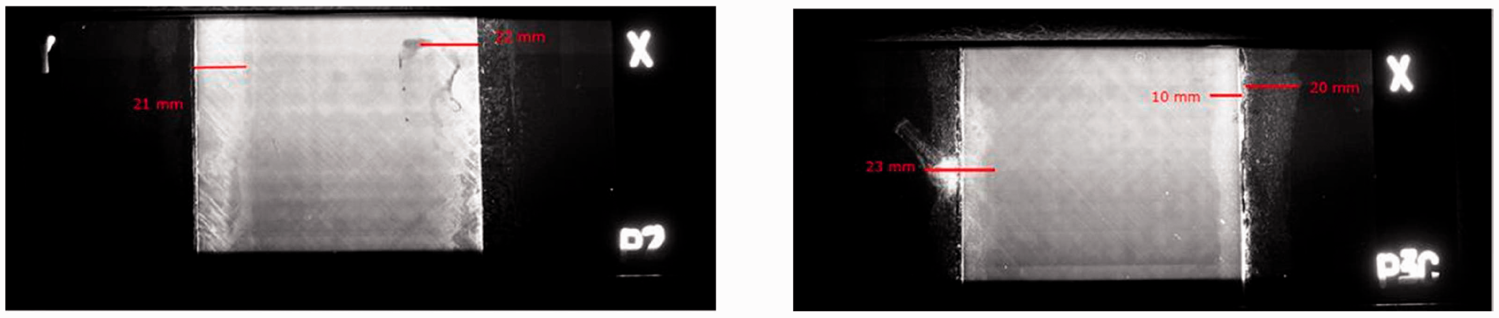
The impact behaviour of the joints reinforced by the metallic spiked sheets is compared with the same impact energy levels demonstrating the capability of the novel design to contain the damage size. Depending on the energy levels, different failure modes were detected at reinforced joints: delamination, fibres breaking and split at the impact area indicating that the metallic reinforcement is inducing different damage patterns due to the local change of the stiffness driving the different failure modes. This suggests that an optimum design of the metallic reinforcement can be investigated to further reduce the damage size or to address the most appropriate failure modes depending on the load to be transferred. Figure 30 summarizes the results of the impact tests in graphs accounting damage size only for disbonding at bonded flange run out.
Summary graphs of impact tests account damage size only for disbonding at bonded flange run out.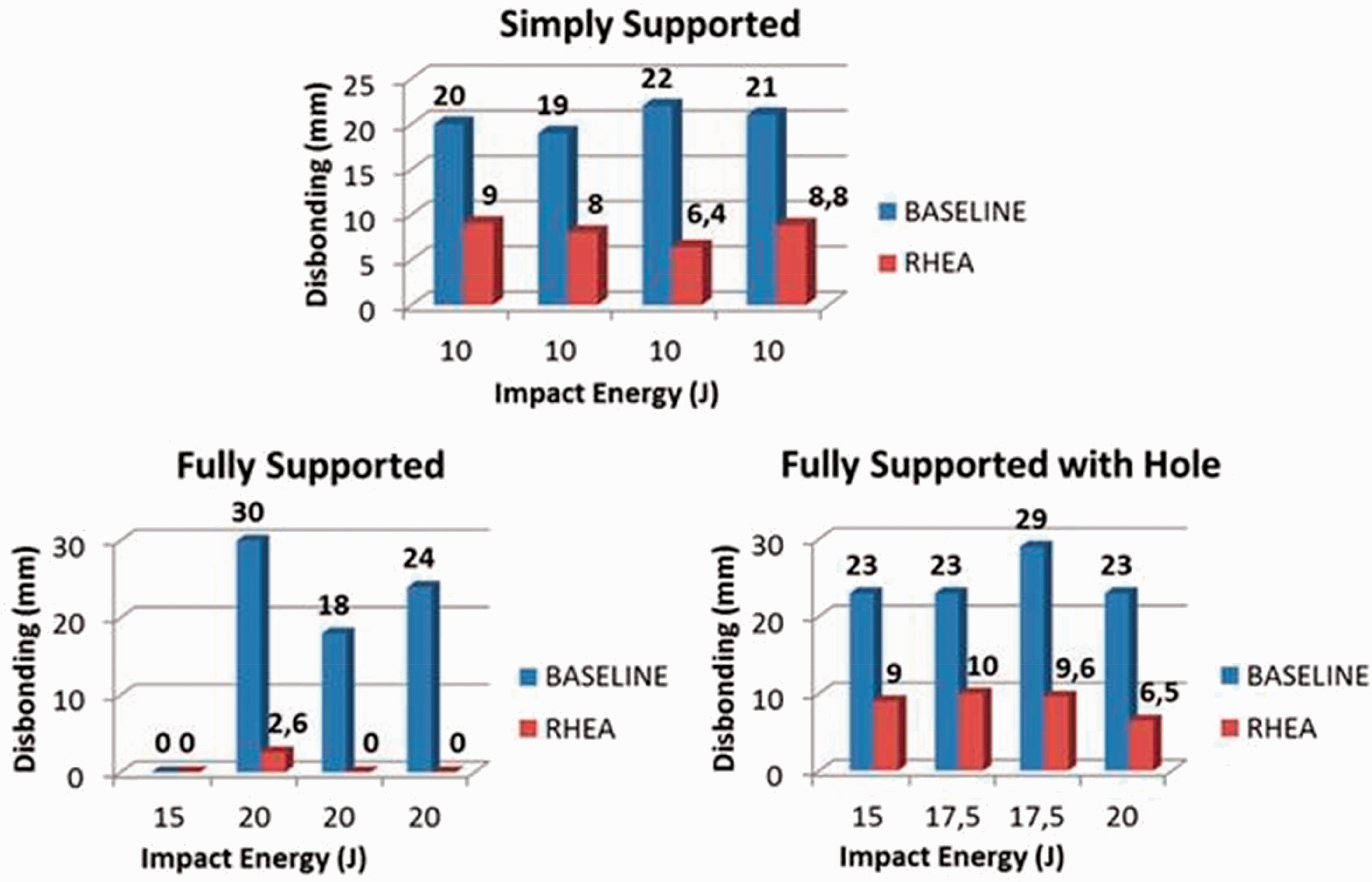
Conclusions
The results obtained during an experimental study carried out to investigate the behaviour of co-bonded joints on composite specimens with a novel design incorporating a through the thickness local reinforcement were presented. This new joint technology is called RHEA and is based on the introduction of spiked metal sheet reinforcement into a CFRP prepreg laminate during its curing cycle. The main concept is to have mechanical interlocking against disbonds and delaminations, and the idea comes from the demand to realize a joint technology that requires minimal design complexity, has low weight, allows fast assembly and avoids point loads. Different specimens were manufactured to investigate static and fatigue behaviour, as well as delamination size after impact and damage tolerance characteristics.
The experimental results show that the static strength as well as the fatigue strength of the reinforced joint is significantly higher than the co-bonded baseline solution. The damage progression under cycling load was delayed by the novel through-thickness reinforcement enhancing the damage tolerance of the joint by means of bridging mechanisms of the load. The through thickness metallic pins provide a secondary load path, resulting in crack growth rates lower than co-bonded solutions by an order of magnitude for both tensile and compressive loading fatigue.
The tests study gathered a significant number of experimental results. General conclusions cannot yet be taken because they would require a higher number of tests considering both more specimens to be tested in the same conditions as well as additional load conditions. In any case, the obtained results show that, in most of the cases, the damage progression under fatigue results significantly delayed by the RHEA reinforcement with respect to the solely adhesive structural bonding. From the tests results, it can be observed that the joints reinforced by this inter-laminar metallic spiked sheet at the bond line provide a low cost innovative 3D reinforcement and seem to have the potential to improve damage tolerance characteristics when compared to a co-bonded joint. The resulting combination of adhesive and mechanical load transfers allows more progressive failure mechanisms.
The RHEA joint provides high damage tolerance of adhesive bonded CFRP joints, reduces process time of sub/assembly or assembly of CFRP structures due to removal of fasteners, and at the same time reduces fasteners cost, and cost of drilling and fastening. It results in a novel type of joining method for producing bonded composite joints with metallic spiked foils integrated in a bonded CFRP joint that can act as a mechanical arrestor. It can be used with co-bonded or co-cured joints and has a potential application as reinforcement of stringer run-outs.
Footnotes
Acknowledgements
The authors are grateful to Airbus Group Innovations, and in particular to Elke Hombergsmeier, Ana Carolina Nogueira and Michael Juergens, for having provided the specimens with the RHEA reinforcements. The authors would also like to thank Valentina Buratti, Alberto Caruso and Paolo Rubini, who helped in performing the tests at the Politecnico di Milano.
Declaration of Conflicting Interests
The author(s) declared no potential conflicts of interest with respect to the research, authorship, and/or publication of this article.
Funding
The author(s) disclosed receipt of the following financial support for the research, authorship, and/or publication of this article: Airbus Operations GmbH, Germany.