
Abstract
The structure of the transmitting and receiving coil in inductively coupled power transfer (ICPT) systems has a significant impact on the system’s performance. To develop a more flexible coil structure, we theoretically analyzed the impedance variations in high-frequency coil mutual inductance circuits and proposed the concept of a coil coupling body (CCB). By using two coils with mutual inductance, a combined CCB was constructed. The CCB can function as an independent coil and its values of L, C, and R can be modified by adjusting the mutual inductance coefficient between the coils in the coupling body. Using the CCBs as the primary and secondary sides of the system, a novel inductive wireless power transfer system was established. Also, by adjusting the mutual inductance, the impedance and resonance state of both the primary and secondary sides can be modified. Preliminary experimental studies show that the inductive power transmission system constructed with CCB not only facilitates tuning, but also exhibits good anti-offset performance.
Keywords
Introduction
Improving tuning convenience, increasing power transmission efficiency, and achieving good offset resistance have always been key goals for contactless power transmission systems. Since the coil structure and circuit topology significantly influence the performance of the transmission system, extensive research has been conducted in this field for a long time. The structures of the transmitting and receiving coils in ICPT system are generally divided into two types: one connects the inductive coil in parallel or series with an external capacitor, achieving circuit matching by setting appropriate parameters. Boys and Green made significant contributions in this area.1–5 The other type utilizes a simple coil structure that eliminates the need for external capacitors. In 2007, MIT proposed a radio energy transmission method based on the principle of magnetic coupling resonance. Kurs et al. innovatively utilized the parasitic capacitance of high-frequency coils as the resonant capacitance, simplifying the coil structure.6–8 Subsequently, many researchers have refined and optimized this electrical energy transmission method. Vera et al. adopted the method of compensating the coupled circuit to enhance the power factor of the system, thereby improving the energy transmission efficiency.9–16 The circuit topology also has a significant impact on system performance. An appropriate circuit topology can improve the energy conversion efficiency. The LLC resonant structure was proposed to enhance the power characteristics of the system in a study by Zhao et al. 17 Sohn et al. analyzed the characteristics of the SS topology and pointed out that when the coupling coefficient is too small, the system is prone to overcurrent problems. 18 In the research by Vu et al., a bilateral LCC compensation topology was applied to achieve constant current and constant voltage output in the ICPT system. 19 Furthermore, reducing the energy loss in the transmission devices is also a way to improve energy transmission efficiency. For example, in studies by Umetani, Bo, Ehrlich et al., the composition and influencing factors of the Litz wire resistance were analyzed in detail, and these research results can be used as a reference during the system design.20–22
Placing relay coils in the transmission channel helps improve transmission efficiency. Through near-field coupling, relay coils can reduce energy attenuation in the transmission path, thereby extending the transmission distance. For example, Lee et al. analyzes and compared the transmission characteristics of the single-relay coil structure and the four-coil structure, proving that the transmission efficiency of the system can be improved by optimizing the structural spacing of a single relay coil. 23 In their paper, LEE et al., pointed out that when the distance between the transmit coil and the receive coil remains unchanged, the transmission efficiency increases with the number of relay resonant coils. However, once the number of relay coils reaches a certain threshold, the efficiency gradually decreases. 24 Farajizadeh et al. established the transfer function and parameter model for complex coils, thus simplifying the complexity of system analysis. 25
In existing contactless power transmission systems, the L, C, and R values of the primary and secondary coils are unchangeable. Due to changes in the environment and load, the system may lose its resonance, resulting in a significant reduction in transmission capacity. Since the parameters of the coils are unchangeable, the system cannot be adjusted to restore resonance after detuning. Aiming at the above issue, we studied composite coils and proposed the concept of CCB, theoretically analyzed the characteristics of the coupling body and proved that its L, C, and R can be adjusted by using the mutual inductance coefficient. When the CCB is applied to an inductive power transmission system, the coupling element parameters can be adjusted to restore the system to resonance after detuning, and the system exhibits strong anti-offset capability. The contribution of this paper lies in: firstly, the theory of the CCB is proposed and its parameter model is established. Secondly, a method for adjusting the parameters of the capacitive coupler is provided, and its feasibility is explored for application in contactless power transmission systems.
Coil coupling body theory
Impedance analysis of high-frequency coil mutual inductance circuit
The coil under high-frequency excitation condition is not an ideal inductor, as described in Figure 1, where R, C and L represent resistance, parasitic capacitance and the inductance of the coil, respectively.
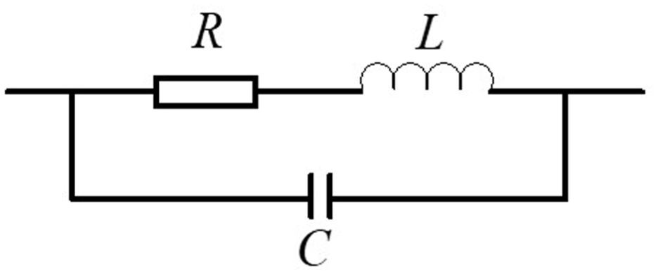
Coil model for high-frequency conditions.
Figure 2 shows the mutual inductance coupling circuit formed by two high-frequency coils H1 and H2, where L1, C1, R1 and L2, C2, R2 are the inductance, parasitic capacitance and resistance of coils H1 and H2, respectively. Power supply V1 provides electric energy to the closed loop where coil H1 is located, and L2 obtains electric energy and generates current I4 through mutual inductance coupling with L1. M is the mutual inductance coefficient between the two coils and ω is the frequency of the power supply.
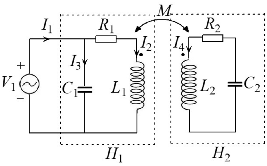
Mutual inductance circuit with two coils.
According to Figure 2, the input impedance of the circuit is obtained as follows:
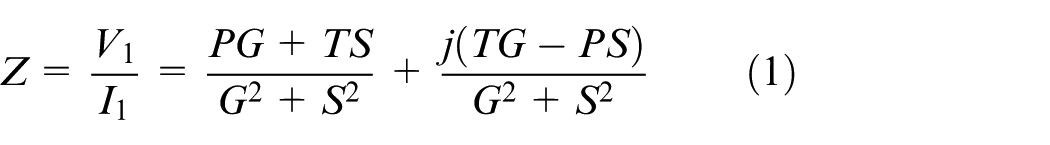
Where,
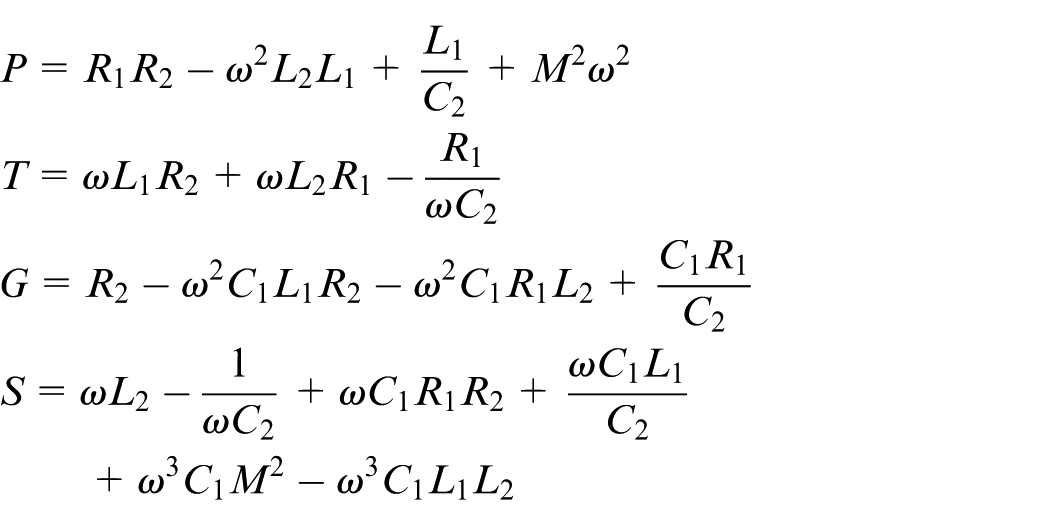
Equation (1) contains real part and imaginary part, where the real part represents the resistance of the circuit and the imaginary part represents the reactance of the circuit. The expressions of both real part and imaginary part contain the mutual inductance coefficient M, which indicates that the change of the mutual inductance coefficient M will cause changes of the impedance characteristics of the circuit.
Resistance of coil mutual inductance circuit
Substitute the expressions of P, G, T and S into the real part of equation (1) yields the numerator of the real part, as described in equation (2).
It can be seen from equation (2) that the real part of the mutual inductance circuit impedance expression contains the mutual inductance coefficient M. If M changes, the value of the real part also changes. The real part of equation (1) represents the resistance of the mutual inductance circuit, so the resistance of the mutual inductance circuit is variable. When other parameters of the circuit remain unchanged, the resistance of the mutual inductance circuit can be changed with M.
If
Equation (3) shows that theoretically there is a state of zero resistance in the coil mutual inductance circuit. Of course, (3) does not always hold, and it is only possible to achieve the zero state of the resistance if the values of L, C, and R of the two coils can make the right part of (3) positive. In fact, due to the existence of skin effect and core loss, zero resistance may only be an ideal state.
Reactance of coil mutual inductance circuit
The imaginary part of (1) represents the reactance characteristics of the mutual inductance circuit, and the numerator of the imaginary part can be expressed by (4). The value of (4) is related not only to the parameters of the two coils, but also to the mutual inductance coefficient M, which indicates that the purpose of changing the circuit reactance can also be achieved by changing M.
Equation (4) is slightly complicated, which needs further discussion. If the frequency and the parameters of the two coils are treated as constants, then (4) is an equation with respect to the unknowns M2. Here we let

Then the solution to (4) is:
When the mutual inductance coefficient M satisfies equation (5), the reactance of the coil mutual inductance circuit is zero, and resonance occurs in the system. The resonance phenomenon occurs because the mutual inductance between the coils causes the capacitance and inductance equivalent of the circuit to change, thus the condition of frequency resonance is satisfied. Equation (5) is conditional and (6) must be met.

This condition is closely related to the parameters of each coil in the circuit, and not all coils with arbitrary parameters can achieve resonance. The squared expression used here is to simplify the mathematical representation of M. However, the physical significance of M remains unchanged, which still represents the mutual inductance coefficient between coils.
Coil coupling body
Definition of CCB
In this paper, a combined coil composed of two or more coils with mutual inductance is called a CCB, which has two important characteristics: one is that the CCB is composed of two or more coils, and the other is that the L, C and R of the CCB are adjustable and regulated by the mutual inductance coefficient M.
Principle of CCB
Equation (7) is the input impedance expression of R, L and C series circuit in Figure 3. Comparing (1) and (7) shows that they are identical in form, except that the structure of the real and imaginary parts in equation (1) is more complex. This suggests that for the circuit shown in Figure 2, we can regard the combination of coils H1 and H2 as a single coil. This combination also has the physical characteristics of a separate coil, and its function is the same as a single coil, except that its R, L, and C are variable. We call the combination of H1 and H2 a CCB.
RLC series circuit.
Parameters of the CCB
Both the real and imaginary parts of (1) are complex expressions, rather than as simple as the impedance expression for a series circuit of R, L, and C in Figure 3. According to (1), the inductance, capacitance and resistance of the CCB are expressed by (8), (9) and (10), respectively. Each of the above equations contains the mutual inductance coefficient M, thus changing M can adjust the impedance of the CCB. Since the CCB still has the characteristics of a coil and its parameters are variable, it can better adapt to systems with variable parameters, which is the value of the CCB.
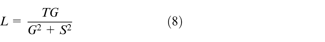
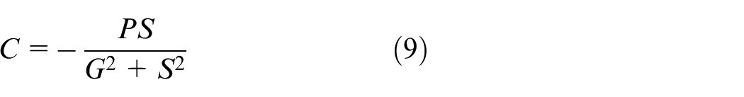
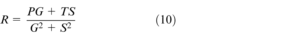
Since the expressions for L, C, R and Q of the CCB are complex, simplified expressions (8), (9), (10) and (11) are used to express them respectively.
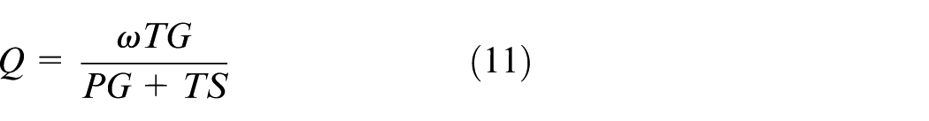
The quality factor is an important characteristic of the coil. Expression (11) of the quality factor Q of the CCB is expanded to obtain expression (12). The denominator of equation (12) contains multiple terms with mutual inductance coefficient M, which indicates that changing M can adjust the quality factor Q of the CCB. The experimental system described later in this paper makes full use of this characteristic of the CCB.
Both the real and imaginary parts of (1) are complex expressions, rather than as simple as the impedance expression for a series circuit of L, C, and R (Figure 3). According to (1), the inductance, capacitance, resistance and quality factor of the CCB can be respectively expressed by (8), (9), (10) and (11). Each of the above formulas contains the mutual inductance coefficient M, so changing M can adjust the values of L, C, R and Q of the CCB. This is completely different from ordinary coils, whose L, C, R and Q values are immutable. The CCB is essentially still a coil, but its structure is different from that of ordinary coils. It is composed of multiple coils combined together, and its parameters are determined by both the parameters of the individual coils that make it up and the mutual inductance coefficient. Since its parameters are variable, it can better adapt to systems with changing parameters, which is exactly the value of the CCB. For example, in an AC resonant system, when the frequency of the excitation power supply changes, the system can be brought back to resonance by adjusting the parameters of the CCB.
Influence factors of mutual inductance coefficient of CCB
Since changing the mutual inductance coefficient M can change the inductance, resistance and capacitance of the CCB, it is very important to find a way to change the mutual inductance coefficient between the coils in the coupling body, because that means that we can adjust the impedance of the CCB.
Structural factors of the coils
Firstly, discuss the variation law of mutual inductance coefficient between single turn circular rings, and then generalize it. Figure 4 shows the positional relationship between two parallel single turn circular rings with centers aligned. The radii of two coaxial circular rings A and B in the Figure 4 are a and b, respectively, and the distance between the centers is d. The axis passing through the two centers and perpendicular to the plane of the two circular rings is the Z-axis. A coordinate system is established where the X, Y, and Z axes are perpendicular to each other. The mutual inductance coefficient between the two coils can be expressed by (13) . 26
Two coaxial parallel rings.
Here,
For a multi-turn coil with turns number N1 and N2 respectively, the coil can be approximately regarded as an ideal electrified ring without turn spacing, then the integral lengths of the two coils are N1 and N2 times of the single-turn coil respectively, that is, 2πN1 and 2πN2, According to (13), the mutual inductance coefficient M between the multi-turn coils can be obtained:
In (14), a, b, N1 and N2 represent the size and structure parameters of the two coils, and d is the coil spacing, which indicates that the mutual inductance coefficient M between the coils in the CCB is related to the coil spacing, size and structure.
Measurement of mutual inductance coefficient
To actually explore the variation law of the mutual inductance coefficient of the CCB, relevant experiments were carried out using two CCB. In the first CCB, 1 coil had a diameter of 30 cm and 5 turns, while the other coil had a diameter of 20 cm and 3 turns. Adjust the coil spacing d, simultaneously record the corresponding value of M, and display the result in Figure 5.
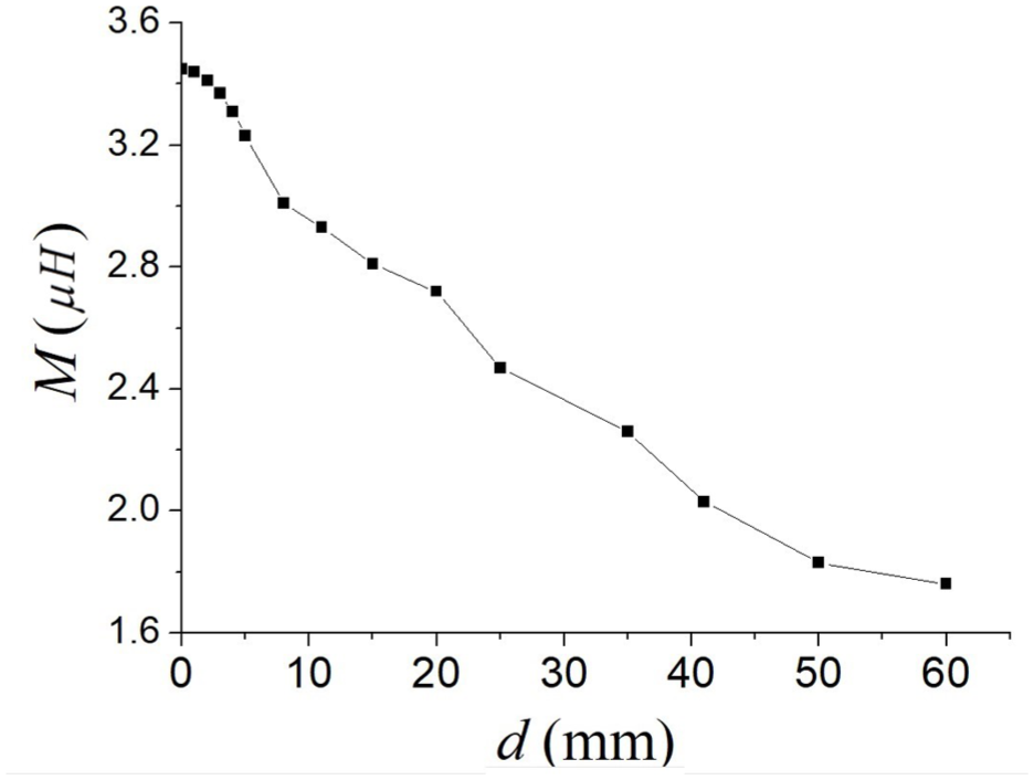
The curve of M varying with d when the diameter ratio is 1.5.
In the second CCB, 1 coil has a diameter of 30 cm and 5 turns, while the other coil has a diameter of 10 cm and 3 turns. The experimental results are shown in Figure 6.
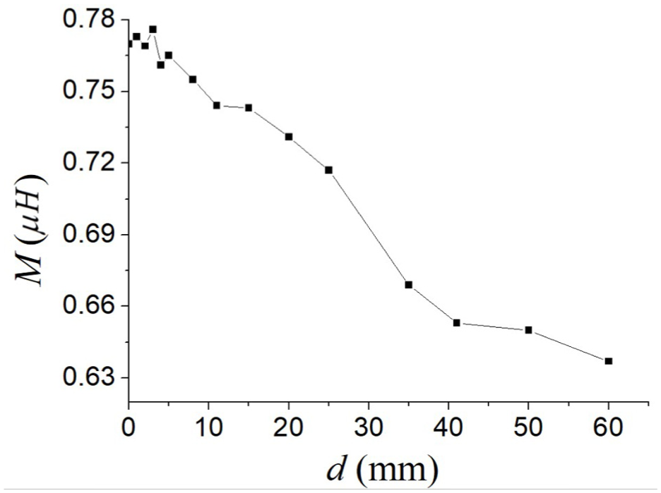
The curve of M varying with d when the diameter ratio is 3.
Figures 5 and 6 show that the mutual inductance coefficient decreases with the increase of the coil spacing. When the coil spacing is the same, the greater the difference in diameter between the two coils, the smaller the value of M.
Inductive power transmission systems
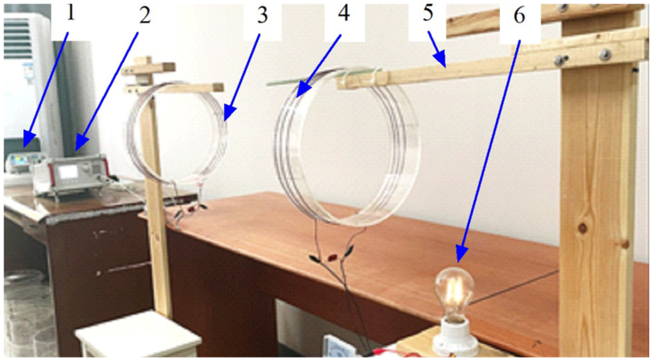
We applied the CCB theory to the inductive power transmission process and constructed a new contactless power transmission experimental system (Figure 7).
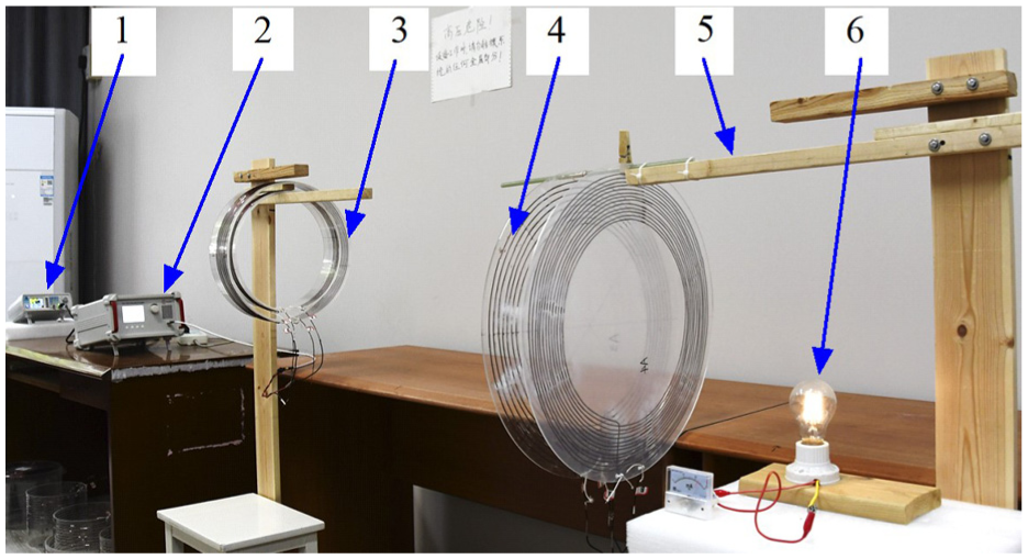
Inductive power transmission system: (1) signal generator, (2) AC power amplifier, (3) primary-side CCB, (4) secondary-side CCB, (5) wooden stand, and (6) bulb load.
The system consists of a signal generator, an AC power amplifier, a primary-side coil, a secondary-side coil and a load, where a CCB is used for the primary-side and secondary-side coils instead of a single coil. The frequency of the signal generator output signal is 1–15 MHz. The AC power amplifier model is ATA-8202, which has a maximum output power of 20 W, operating frequency range of 100 khz–20 MHz, and output impedance of 50 Ω. The load is a 5 W bulb.
Primary-side coil
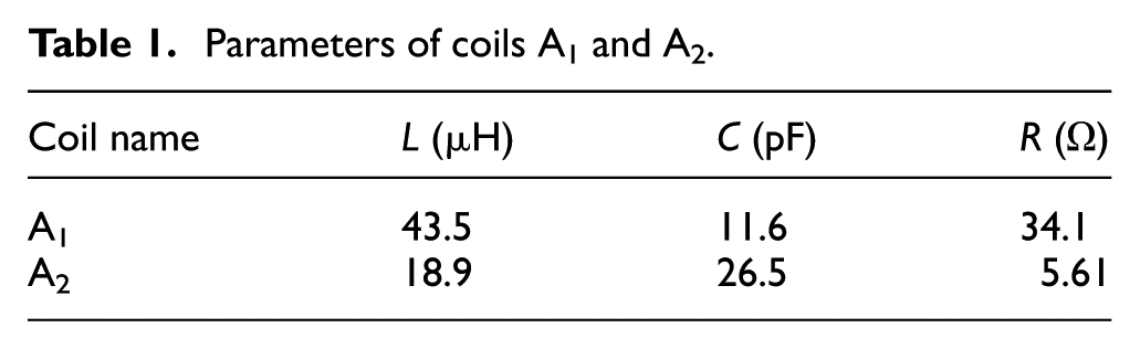
The primary-side coil of the system is a CCB composed of two cylindrical coils A1 and A2 with different diameters (Figure 8(a) and (b)). The parameters of the two coils are listed in Table 1. The coils are wound with copper wire and the diameter of the turns is 1.5 mm. Place the small-diameter coil A2 in the large-diameter coil A1 and make the central axes of the two coincide as much as possible to form a CCB (Figure 9).
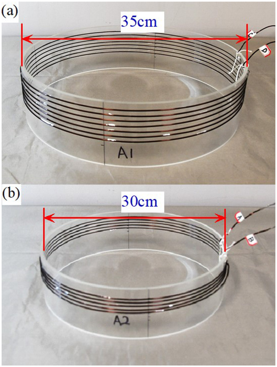
Coils constituting the primary-side coupling body: (a) large diameter coil A1 and (b) small diameter coil A2.
Parameters of coils A1 and A2.
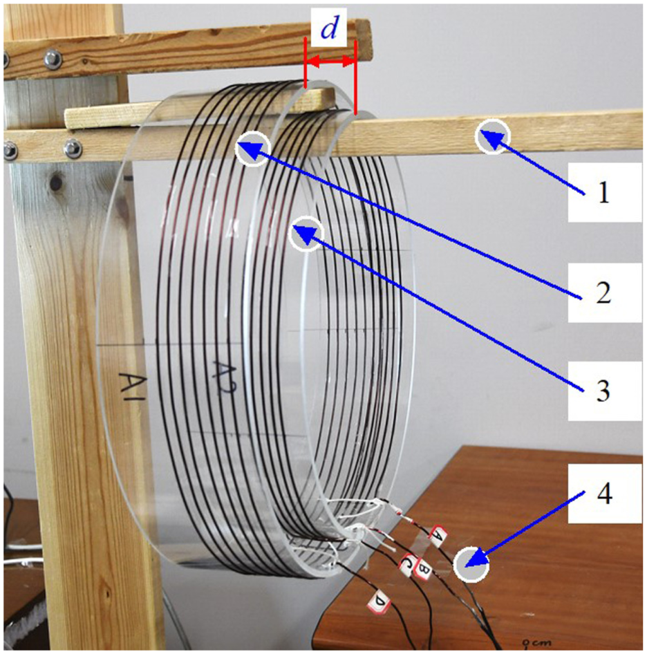
Primary-side coupling body: (1) wooden pole, (2) coil A1, (3) coil A2, and (4) terminals of the coils.
Here, the distance between the bottom surfaces of two coils is defined as the coil spacing d (Figure 9). The method of changing d is as follows: the coupling body is suspended on the horizontal wooden pole, and the coil A2 is kept stationary. The coil spacing d can be changed by making the coil A1 move horizontally along the wooden pole. The mutual inductance coefficient between the two coils is changed by adjusting the coil spacing d, so that the resistance, inductance and capacitance of the coupling body can be changed. The primary-side coupling body has four terminals: A, B, C, and D, and the terminal combination mode used in the experiment is AD + B, which means that terminals A and D are connected as one input of the power supply, and terminal B is the other input of the power supply. The equivalent circuit of the primary-side is shown in Figure 10.
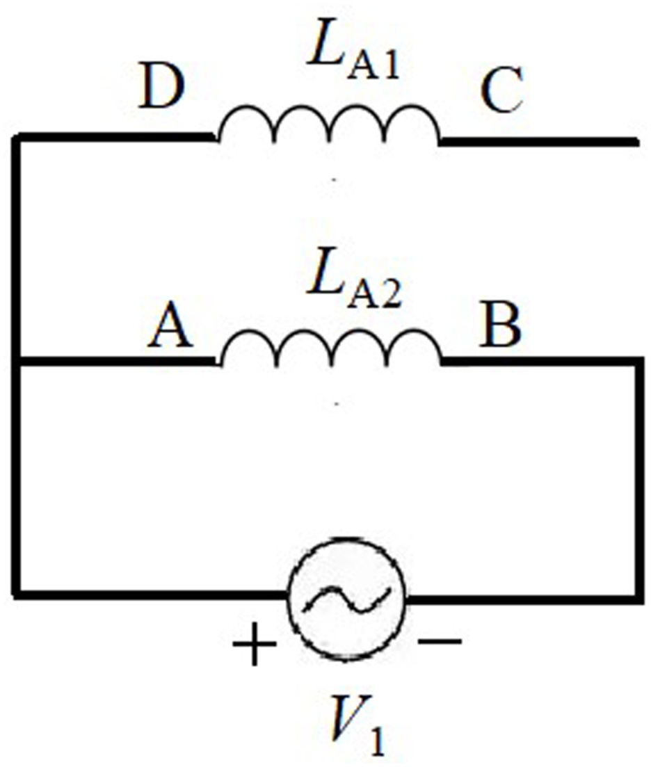
The equivalent circuit of the primary-side.
It should be noted that the system designed in this paper is completely different in structure from wireless power transmission systems that incorporate relay coils. The power transmission part of the latter includes the primary-side, the secondary-side, and the relay coil, which is neither part of the primary-side nor the secondary-side and is relatively independent. In contrast, the power transmission link in the system designed in this paper only involves the primary-side and the secondary-side, except that both the primary-side and the secondary-side are coupling bodies composed of two coils.
Secondary-side coil
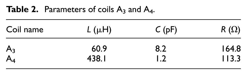
The secondary-side coil of the system uses a coupling body composed of two planar spiral coils A3 and A4 (Figure 11(a) and (b)). The planar coil is made by winding the wire on a plastic plate and fixing it with glue. The winding diameter is 1.5 mm, and the number of turns of coils A3 and A4 is 8 and 11 respectively. Their other parameters are listed in Table 2. Place two coils in parallel and align the centers as much as possible to form a CCB. The method to change the coil spacing d is to drill a hole in the plastic base of the coil, suspend the coupling body on a horizontal plastic rod (Figure 12), hold the coil A4 stationary, and move the coil A3 horizontally along the plastic rod. By adjusting d, the mutual inductance coefficient between the two coils is changed, thereby changing the impedance of the coupling body. The secondary-side coupling body has four terminals: A, B, C, and D, and the terminal combination mode used in the experiment is (BC; A + D), which means that terminals B and C are connected, and terminals A and D are connected to the two inputs of the load respectively. The equivalent circuit of the secondary-side is shown in Figure 13. In Figure 13, R L is the load, which is the light bulb in the system.
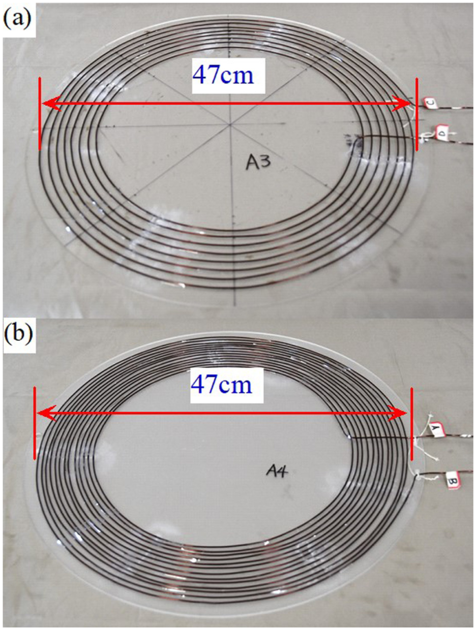
Coils constituting the secondary-side coupling body: (a) coil A3 and (b) coil A4.
Parameters of coils A3 and A4.
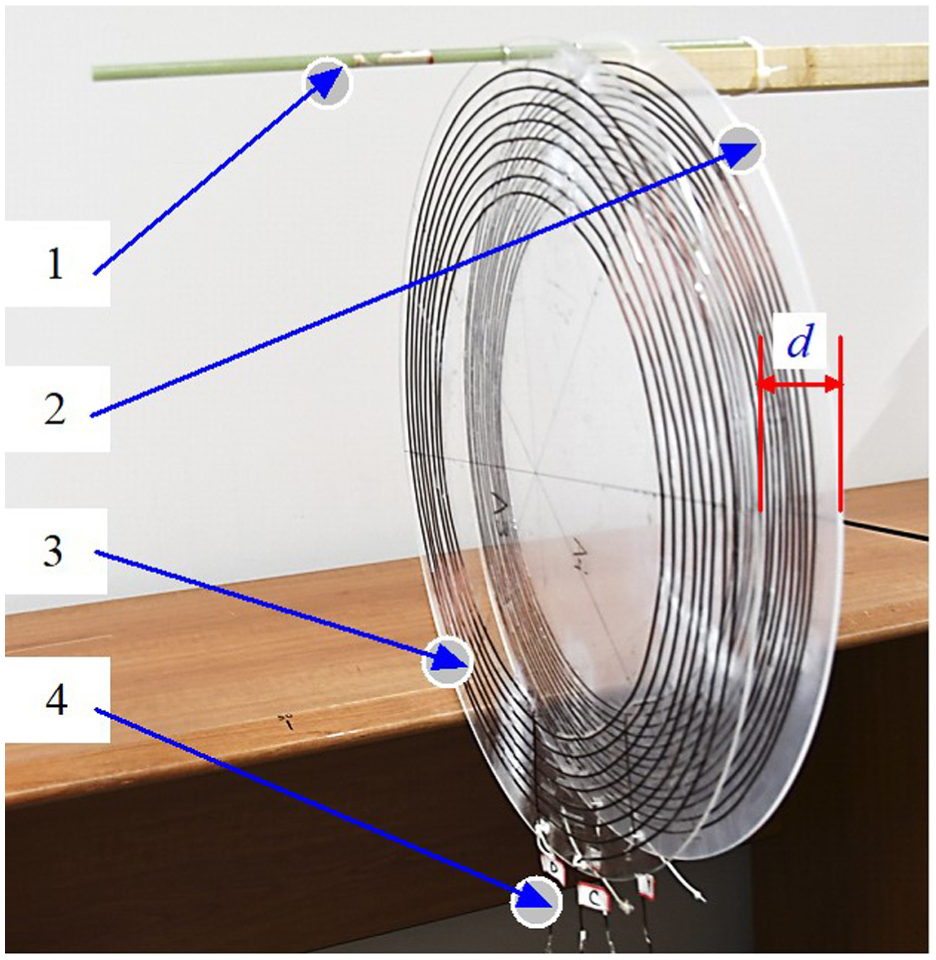
Secondary-side coupling body: (1) plastic rod, (2) coil A4, (3) coil A3, and (4) terminals of the coils.
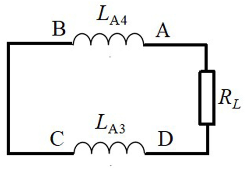
The equivalent circuit of the secondary-side.
Experiments
Power transmission experiment
The purpose of the experiment is to investigate whether the change of mutual inductance coefficient can affect the power transmission efficiency. The coil spacing of the primary-side and secondary-side coupling bodies is represented by d1 and d2 respectively. Changing d1 and d2 means changing the mutual inductance coefficient of the CCB. During the experiment, the frequency of the signal generator was set to 7.11 MHz and the transmission distance was 40 cm. The transmission efficiency is obtained by measuring the output power of the primary-side and the load power. The experimental results are shown in Table 3, where P1 and P2 are the power of the primary-side and the load respectively. It should be noted that the parameters of each coil mentioned earlier were obtained under the condition of a frequency of 7.11 MHz.
Power transmission efficiency.
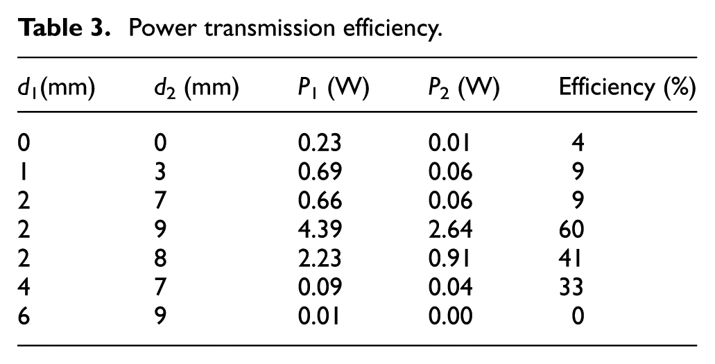
Table 3 illustrates: When the coil spacing changes, both transmit power and load power will change. The reason is that the change of the mutual inductance coefficient causes the impedance of the CCB to change, causing the current of the primary-side and secondary-side coupling bodies to change, resulting in fluctuations in transmission efficiency. Experiments show that there is an optimal match between the coil spacing d1 and d2, and when d1 = 2 mm and d2 = 9 mm, the transmission efficiency is the highest. Experiments also show that under the condition of constant power supply frequency, retuning can be achieved by adjusting the coil spacing of the CCB. This is of great significance because in practical applications, detuning may occur due to factors such as changes in the load position. At this time, adjusting the coil spacing of the coupling body can restore the system to the resonant state.
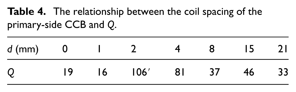
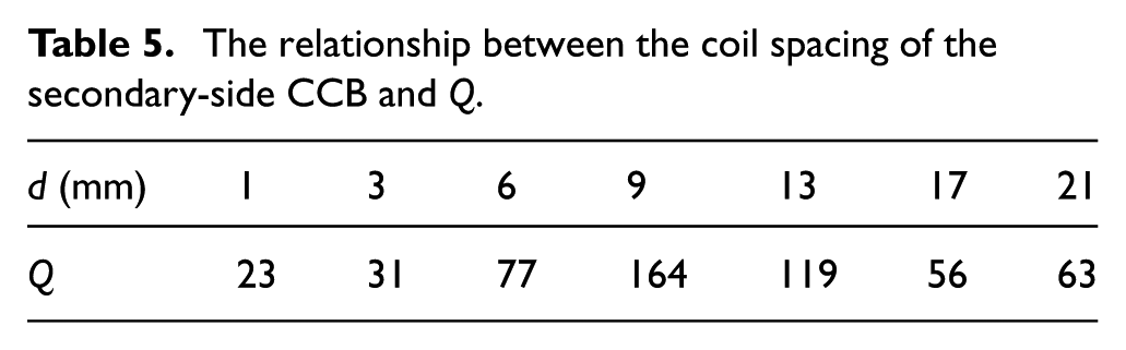
The quality factor of the coil has a significant impact on the transmission efficiency of the system, and an important feature of the CCB is that its Q value is adjustable. Tables 4 and 5 show the relationship between the Q value of the primary-side and secondary-side and the coil spacing d. Figures 14 and 15 also illustrate this relationship. By adjusting the coil spacing, when the Q values of both the primary-side and secondary-side reach their maximum, the system achieves the highest transmission efficiency.
The relationship between the coil spacing of the primary-side CCB and Q.
The relationship between the coil spacing of the secondary-side CCB and Q.
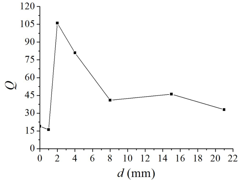
The relationship between the coil spacing of the primary-side CCB and Q.
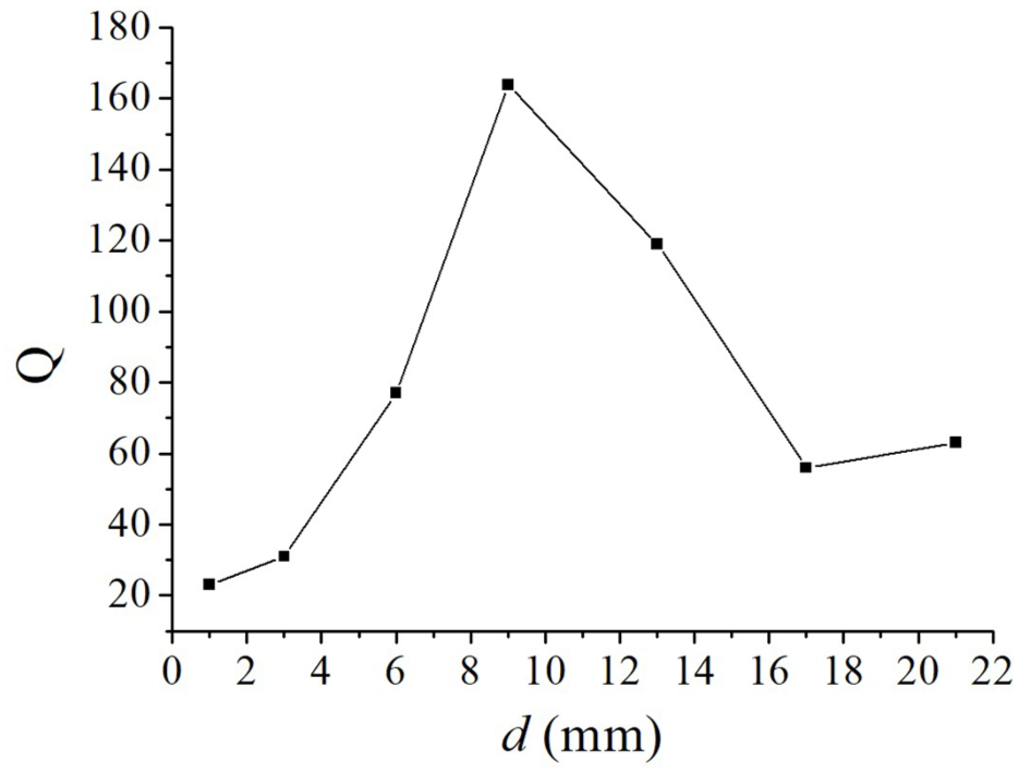
The relationship between the coil spacing of the secondary-side CCB and Q.
The main reason for the low transmission efficiency is the low coupling coefficient. Since the coupling coefficient is related to various factors such as the size of the coil, circuit topology, quality factor, power supply frequency, etc., it is necessary to carry out optimized design for the system. These works will be carried out by us in the future.
Frequency adaptability experiment
In order to test the influence of power supply frequency on system transmission efficiency, related experiments were carried out. The experimental method is to change the power supply frequency while keeping the transmission distance unchanged. For each frequency, the coil spacing of CCB on the primary-side and secondary-side must be adjusted simultaneously to find maximum transmission efficiency. The maximum efficiency corresponding to the frequency is shown in Figure 16. It can be seen from the figure that the maximum transmission efficiency corresponding to different frequencies is also different, which is mainly because the power supply frequency has a great influence on the Q, L, and R values of the CCB. The internal resistance of the CCB at different frequencies is different, and the coupling coefficient between the primary-side and secondary-side is also different.
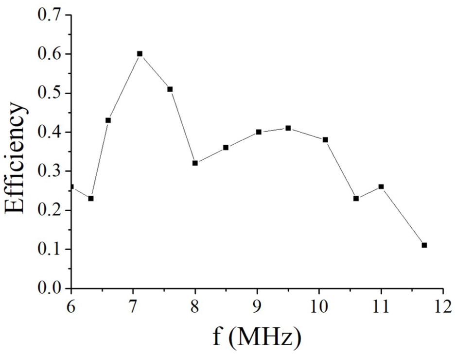
The relationship between efficiency and frequency.
Anti-lateral misalignment experiment
Anti-offset ability is also an important indicator to evaluate the performance of contactless power transmission systems. In the actual ICPT system, the secondary-side is usually installed on the mobile device, for example, in the wireless charging system for electric vehicles, the secondary-side is installed on the vehicle. Consequently, during charging, the misalignment between the primary-side and secondary-side often occurs, which generally leads to a decrease in the efficiency of power transmission. In severe cases, the system may even fail to operate. To test the lateral offset resistance capability of our system, relevant experiments were conducted. The experimental conditions are as follows: the power frequency is 7.11 MHz, and the transmission distance was 40 cm. By changing the lateral offset distance D between the secondary-side and the primary-side, the corresponding transmission efficiency is measured. The measurement results are shown in Table 6.
Results of the lateral misalignment experiment.
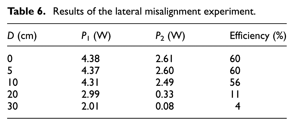
It can be seen from Table 6that when the lateral offset is less than 10 cm, the efficiency of the system remains basically stable, which means that the system has a good ability to resist the lateral offset of the secondary-side.
Anti-metal interference experiment
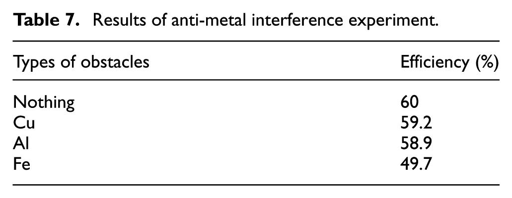
In order to study the anti-metal interference ability of ICPT systems, the three most common metals, iron, aluminum and copper were selected as obstacles, and the interference caused by the existence of different metal obstacles on wireless power transmission systems was compared. The experimental device still used the one described earlier, and all the operating parameters of the equipment remained unchanged. A metal plate with dimensions of 200 mm × 200 mm × 1 mm was placed in the middle of the primary-side and secondary-side and parallel to the coil (Figure 17). The changes in the system’s transmission efficiency under the conditions of different metal plates were observed. The experimental results are shown in Table 7.
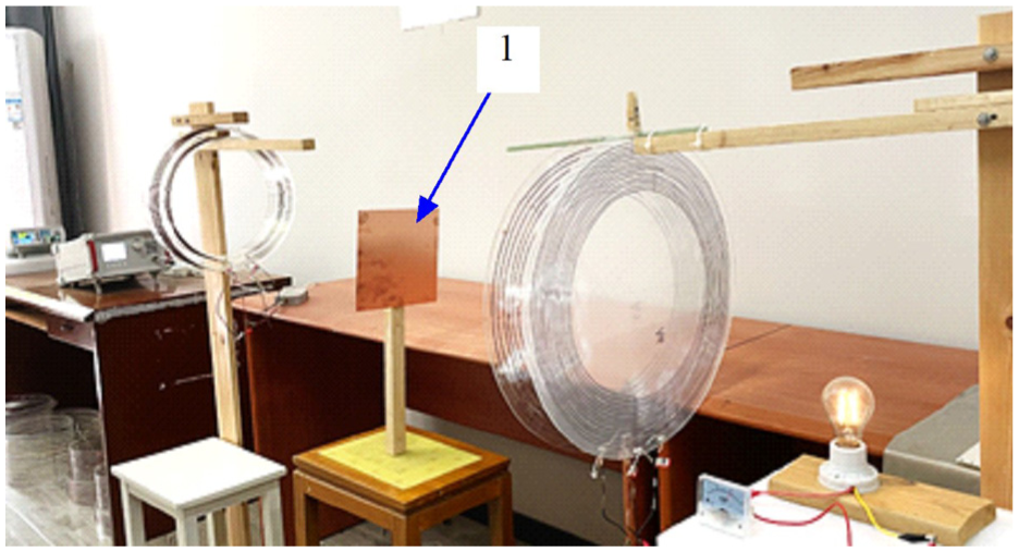
Anti-metal interference experimental system.
Results of anti-metal interference experiment.
(1) Thin metal plate.
As can be seen from Table 7, when copper and aluminum are used as obstacles, the transmission efficiency of the system does not decline significantly. However, when iron is used as an obstacle, the transmission efficiency drops significantly. The reason for the above phenomenon lies in the different relative permeability of the three metals. The relative permeability of iron is much higher than that of copper and aluminum. The higher the relative permeability of the obstacle, the greater the decline in the quality factor of the system, the more severe the eddy current loss, and at the same time, the system experiences detuning, resulting in a significant decrease in transmission efficiency. 27
Transmission efficiency comparison experiment
For comparison, a common two-coil ICPT system was designed (Figure 18). The inductance and coil diameter of the primary and secondary coils of this system were the same as those of the primary-side and secondary-side CCB mentioned earlier, and both the primary and secondary sides adopted an LC parallel structure. Using the same power supply frequency and transmission distance as in the previous experiments, the maximum transmission efficiency of this system was measured to be 31.3%, which was lower than that of the ICPT system composed of CCB. The main reason for this result lies in the different Q values of the two systems. If the power supply frequency remains unchanged, the values of L and R of the ordinary coil are also stable, meaning that the Q value of the ordinary coil is also stable. However, the Q value of the CCB can be changed by adjusting the coil spacing and can be much larger than that of the ordinary coil.
The ICPT system with two coils: (1) signal generator, (2) AC power amplifier, (3) primary-side coil, (4) secondary-side coil, (5) wooden stand, and (6) bulb load.
It should be pointed out that the two systems involved in the comparison only have the same power supply frequency, coil inductance and transmission distance, and other parameters are different, because it is extremely difficult to make an ordinary coil with exactly the same parameters as the CCB, so the previous experimental results do not mean that the transmission efficiency of the two-coil ICPT system is definitely low. The comparison method in this paper is for reference only.
Discussion
The impedance of the CCB is crucial to the performance of the contactless power transmission systems. How to design a CCB with the smallest possible impedance remains a crucial research topic as lower impedance reduces the electrical energy loss of the coil system itself and improve the Q value. Furthermore, the choice of a planar spiral CCB for the secondary side was based on experimental comparisons. Experiments in this paper demonstrated that the planar spiral coupling body, which is adopted, exhibited better anti-deviating properties than a cylindrical CCB. It should be noted that the coils in this paper are all handcrafted, their parameters are unstable, and interference will also be introduced during the measurement process, and the high-frequency system is extremely sensitive to the environment and device parameters, so the experimental results may have considerable errors.
Conclusions
This paper proposes the concept of CCB and applies it to the inductive power transmission system as a novel primary and secondary structure. Experimental results show that the system has good power transmission capabilities, especially in term of retuning and anti-offset capabilities, making it worthy of further research. This system is suitable for applications such as electric vehicle charging, rotating logistics equipment and mobile robots. This is because in these application scenarios, the movement of the target device can cause its relative position with the primary-side coil to be unstable, which effectively utilizes the system’s strong anti-offset performance. Moreover, since the parameters of the coupling body are adjustable, the system can still re-enter the resonant state when the temperature, supply frequency and electromagnetic environment change, thereby maintaining high transmission efficiency. However, there are still many important issues in this paper that have not been resolved, such as methods for improving the efficiency of long-distance power transmission, designing ultra-low impedance CCB and controlling the stability of the parameters of the CCB, etc. It is important to note that the research on applying the CCB to the ICPT system is still in its infancy, and we hope to see more participation in this research in the future.
Footnotes
Ethical considerations
This study does not involve any content related to ethics or consent. This is because the study does not involve human participants, animal experiments, religion, or the privacy of others.
Consent to participate
This study does not involve medical experiments and has no participants or volunteers. Therefore, there is no need to provide a participation consent form.
Consent for publication
I would like to declare that the work described was original research that has not been published previously. All authors agree to transfer the copyright of the manuscript to the publisher.
Funding
The authors disclosed receipt of the following financial support for the research, authorship, and/or publication of this article: This research is supported by the National Natural Science Foundation of China, Project No is 62003205.
Declaration of conflicting interests
The authors declared no potential conflicts of interest with respect to the research, authorship, and/or publication of this article.
Data availability statement
The authors confirm that the data supporting the findings of this study are available within the article.