
Abstract
This paper proposes a novel multisensor fusion ground SLAM system that integrates LiDAR, visual, IMU, and wheel encoder data to enhance localization and mapping accuracy in complex environments. The proposed system consists of a LiDAR subsystem and a visual subsystem. To fully leverage the complementary advantages of LiDAR and visual sensors, the two subsystems provide each other with initial values for optimization. LiDAR supplies high-precision depth information to the visual subsystem, while the visual subsystem assists the LiDAR module in motion distortion correction, thereby enhancing the overall accuracy of state estimation. In addition, a novel plane extraction method is proposed based on adaptive dynamic distance thresholds and normal vector consistency verification. And the planar factor is introduced into the LiDAR subsystem for joint optimization. Constraining continuous planar structures (such as the ground and walls) reduces matching ambiguity, which further decreases local map noise and improves mapping accuracy. The proposed method has been extensively evaluated in complex urban campus scenarios, and the results show the effectiveness and accuracy of the algorithm.
Introduction
In recent years, simultaneous localization and mapping (SLAM) has gained widespread attention and experienced rapid advancement. SLAM has become indispensable for various robot navigation tasks due to its ability to estimate poses and reconstruct maps in real time. 1 The mainstream methods primarily consist of LiDAR-based, vision-based, and LiDAR-vision fusion approaches.
Visual SLAM
In vision-based methods, purely visual SLAM2–4 algorithms, which rely solely on cameras as sensors, offer advantages like being lightweight and cost-effective, and have been widely applied over the past decade. Meanwhile, due to the inability of monocular cameras to recover metric scale, a common solution is to incorporate IMU sensors. An IMU supplies high-frequency inertial measurements, while a camera captures information-rich images. These two sensors complement each other to form a visual-inertial odometry (VIO) system. According to the estimation strategy, VIO can be categorized into two categories: filter-based methods and optimization-based methods.
Filter-based methods5–7 typically use a Kalman Filter 8 and its extended forms to propagate system states. State propagation is accomplished using the IMU kinematic model, while visual updates offer multi-frame constraints. Optimization-based methods9,10 employ a sliding window optimization framework that jointly estimates system states by constructing a multi-modal constrained factor graph. Specifically, a nonlinear least squares optimization problem incorporating visual reprojection constraints, IMU pre-integration constraints is formulated within the sliding window. To address the challenge of precise picking point localization in cluttered lychee clusters, Fcaf3d-lychee 11 enhances the 3D detection backbone with a visual attention mechanism, achieving exceptional precision.
However, the sensitivity of visual SLAM algorithms to illumination changes, as well as the difficulty in extracting sufficient feature points in texture-sparse environments, can still easily result in divergence or failure of localization.
LiDAR SLAM
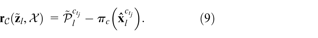
Owing to its capability of accurately measuring point-wise distances and spatial coordinates, LiDAR offers distinct advantages in point cloud registration and high-accuracy motion estimation. Compared with visual SLAM, LiDAR SLAM directly acquires accurate depth information via LiDAR sensors. However, purely LiDAR SLAM12,13 relies on sufficient environmental characteristics during the initialization phase, otherwise, it is prone to failure. Therefore, integrating IMU sensors to assist with distortion correction and provide initial values is a common solution. This sensor fusion approach forms a LiDAR-inertial odometry (LIO) system.
Similarly, LIO can also be categorized into filter-based methods and optimization-based methods. Although state-of-the-art filter-based SLAM methods14–16 can achieve highly accurate and stable localization over short durations, their inability to rectify accumulated pose errors makes them unsuitable for applications requiring globally consistent mapping. While optimization-based LiDAR SLAM methods17,18 achieve high-precision global consistency through factor graph optimization, they are highly sensitive to initialization and prone to getting trapped in local minima under aggressive motion or in feature-scarce environments.
In addition, the performance of LiDAR-based SLAM often degrades significantly in environments with insufficient geometric constraints, such as narrow corridors, tunnels, or large open flat areas.
LiDAR-visual-inertial SLAM
Recently, LiDAR-visual-inertial systems have attracted growing attention owing to their robustness when one sensor fails or is partially degenerated. 19 VIL-SLAM 20 employs a loosely-coupled method without leveraging the joint optimization of LiDAR, camera, and IMU measurements. The LIMO framework 21 establishes cross-modal associations by leveraging LiDAR point clouds to geometrically constrain visual features, subsequently performing keyframe-based motion estimation through bundle adjustment optimization with geometric consistency constraints. In, 20 a cascaded architecture is employed to integrate tightly-coupled stereo visual-inertial odometry, LiDAR odometry, and a LiDAR-based loop-closure module. LIC-Fusion 22 implements a tightly-coupled fusion strategy within the MSCKF 5 framework, which synchronously integrates heterogeneous sensor modalities including IMU kinematic constraints, sparse visual feature tracking, and LiDAR geometric features. The enhanced LIC-Fusion2.0 23 framework refines LiDAR-based pose estimation through sliding-window constrained planar feature association, where consecutive LiDAR scans are processed using plane parameterization and geometric consistency verification within a factor graph optimization architecture. R2LIVE 24 establishes a unified probabilistic framework combining LiDAR, camera, and IMU measurements via manifold-based iterated Kalman filtering. 8 Specifically, its VIO component leverages keyframe-based sliding window optimization with geometric verification to achieve robust visual feature triangulation through maximum a posteriori estimation. R3LIVE 25 employs a hierarchical architecture where LIO establishes the geometric representation of the global map, while VIO concurrently populates photometric attributes through texture rendering. These complementary subsystems maintain joint state estimation via tightly-coupled fusion of heterogeneous sensor streams. R3LIVE++ 26 implements a self-adaptive radiometric compensation framework with real-time exposure parameter estimation and proactive photometric calibration, 27 enabling radiometrically consistent reconstruction of environmental radiation properties across varying illumination conditions. LVI-SAM 28 implements a tightly-integrated multi-modal fusion architecture within a factor graph-based optimization framework, where LiDAR geometric constraints, visual feature observations, and IMU kinematic models are jointly optimized through smoothing-based state estimation. Specifically, its visual-inertial subsystem executes sparse feature tracking while establishing cross-modal depth associations through LiDAR-derived geometric verification. Fast-LIVO 29 and Fast-LIVO2 1 implements a tightly-coupled framework through singular error-state iterative Kalman filtering (ESIKF), which can be updated by both LiDAR and visual observations. SR-LIVO 30 enhances LiDAR scan segmentation by reconstructing point clouds to align with camera timestamps. Once a relatively accurate pose estimation is obtained using LIO, it integrates visual updates, enhancing both pose accuracy and processing efficiency. The study 31 addressed the limitation of locating 3D cracks by introducing an automated detection system that integrates LiDAR and camera data, achieving sub-millimeter measurement precision for 3D structural health monitoring.
In addition, wheel encoder, as a low-cost high-frequency motion sensor, provides stable measurements in GNSS-denied environments. Current LiDAR-visual-inertial fusion methodologies predominantly neglect systematic integration of wheel encoders. Besides, there are a large number of planar features in actual environments, and using continuous planar structures in the scene (such as floors and walls) to construct planar constraints can significantly reduce matching ambiguity in degraded environments. To address these situation, we propose a novel optimization framework for multimodal sensors (LiDAR-Camera-IMU-Wheel) with adaptive planar constraints. The specific contributions are as follows:
A novel multimodal sensor (LiDAR-Camera-IMU-Wheel) fusion optimization framework is proposed, which jointly optimizes visual reprojection residuals, IMU preintegration residuals, wheel encoder preintegration residuals, and LiDAR odometry residuals through factor graphs.
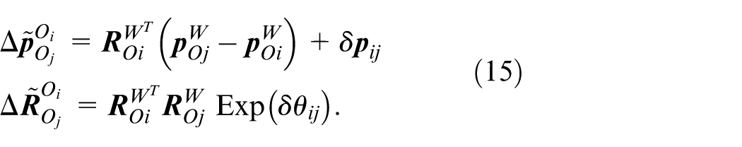
A novel plane extraction method based on adaptive dynamic distance thresholds and normal vector consistency verification is proposed. Additionally, planar factors are integrated into the backend optimization process of the LiDAR subsystem. By imposing constraints derived from planar structures, local map noise is effectively suppressed, and the geometric consistency of the reconstructed environment is rigorously maintained, thereby improving overall mapping accuracy.
Extensive validation in complex urban environments, demonstrating superior localization accuracy and system robustness compared to state-of-the-art SLAM methods.
Methodology
System overview
The overview of the proposed system is shown in Figure 1, with input sensors including LiDARs, RGBD cameras, IMUs, and wheel encoders, while GNSS is optional. The system is primarily composed of two subsystems: the visual subsystem and the LiDAR subsystem. The visual subsystem takes input camera images, IMU measurements, and wheel encoder measurements, with LiDAR data being optionally input. This subsystem achieves state estimation by jointly minimizing visual reprojection residuals, IMU preintegration 32 residuals, and wheel encoder preintegration residuals. The LiDAR subsystem extracts geometric features from point clouds and constructs a LiDAR odometry by matching the features of the current frame to a local map, thereby providing high-precision pose estimation. The back-end employs a factor graph optimization framework, utilizing iSAM2 33 to optimize the system states jointly. Constraints integrated into the optimization include IMU preintegration factors, LiDAR odometry factors, and loop closure factors.
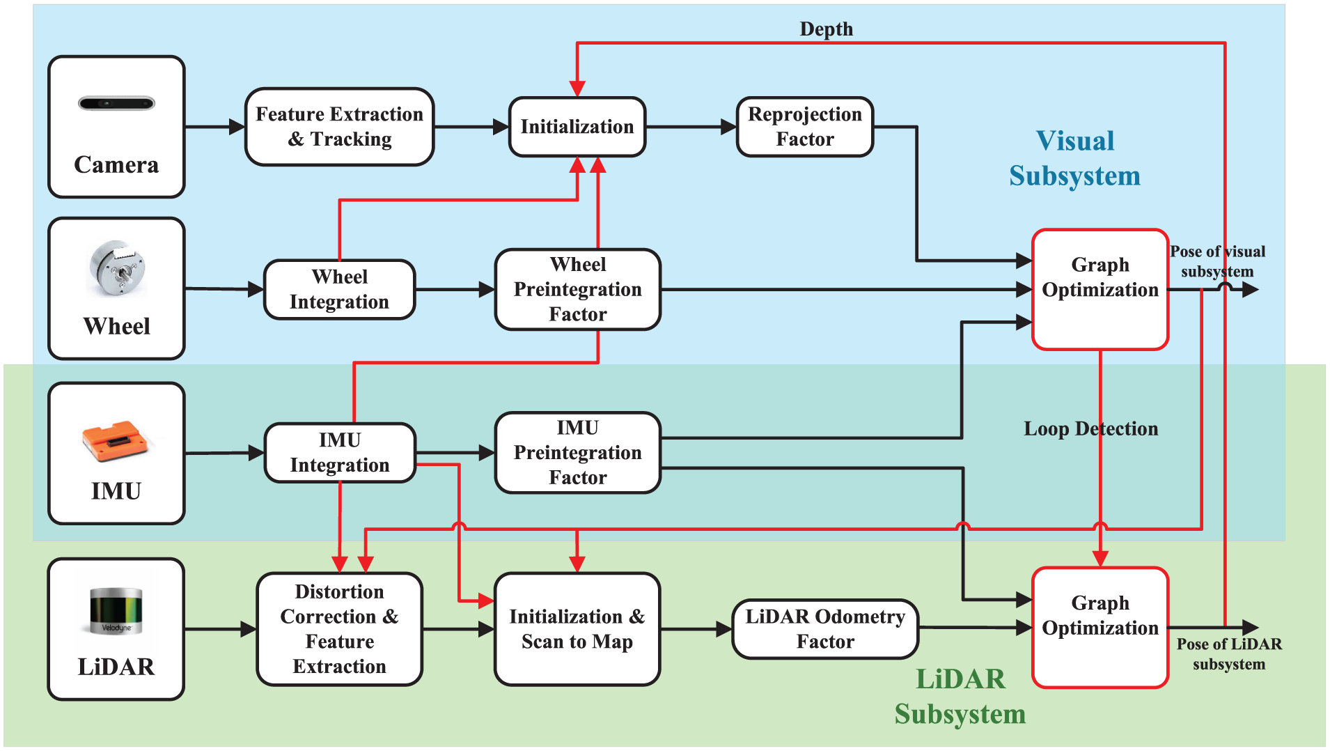
System overview.
Two subsystems solve the state estimation problem using optimization-based methods, where the problem is formulated as a Maximum A Posteriori (MAP) problem. During this formulation, it is assumed that the measurements from different sensors are independent and that their noise follows zero-mean Gaussian distributions. Based on these assumptions, the MAP problem is further converted into a cost minimization problem, where each cost corresponds to the residual of a specific sensor measurement:
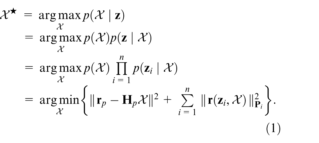
Where
Visual subsystem
The visual subsystem performs an optimization process within a sliding window framework, where the robot state

Where
Improvements in depth estimation and initialization
The processing pipeline of the visual subsystem is improved upon the Ground-Fusion algorithm, 34 which is a low-cost SLAM framework that tightly couples RGBD-IMU-Wheel-GNSS sensors. The more detailed improvements are as follows:
1)
2)
Constraint factors
1)
Where

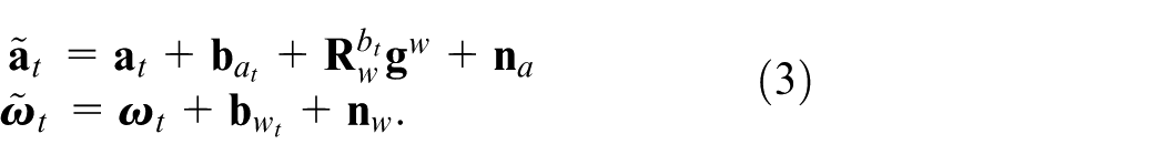
In the process of nonlinear optimization, the state variables are iteratively updated, which requires re-integrating the IMU measurements after each update. To improve the efficiency of the overall optimization process, we employ the preintegration method, where the integration results between time instants
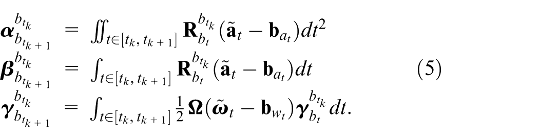
Where
Finally, the IMU preintegration residuals 9 can be expressed as:
2)

Where
Where
3)
By incorporating wheel encoders into the SLAM framework, the system benefits from enhanced scale observability and more robust pose estimation, particularly in scenarios where visual-inertial methods alone struggle. The integration of wheel encoders as an additional constraint within the optimization process allows for improved localization accuracy and system robustness, even in environments with low texture or minimal motion excitation.
To estimate the motion of the robot from wheel encoder measurements, the following kinematic formulation 38 is developed.
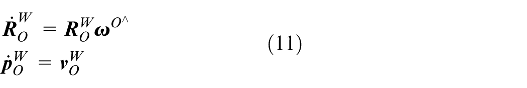
The equation (11) describes the pose transformation of the wheel encoder coordinate system. By integrating (11), the pose at time
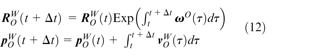
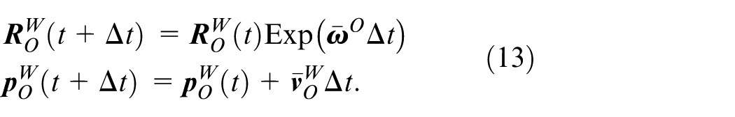
The wheel encoder can provide motion measurement between frames. Based on the midpoint integration, we can derive the wheel encoder measurement model as follows:
Where
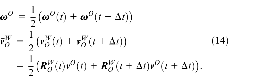
Similar to IMU preintegration, the wheel encoder measurements between keyframe
Where
Based on the wheel encoder preintegration measurement model (15), the wheel preintegration residual can be given by:
Where
Therefore, the final wheel preintegration residual, expressed as a function of the system state, is given by:
Where
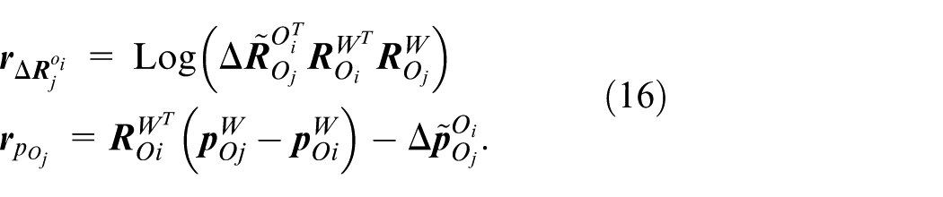
LiDAR subsystem
The LiDAR subsystem is an enhancement based on the LIO-SAM algorithm. 17 The optimization variables in the system are same to those used in the visual subsystem. The system retains the factor graph used for global pose optimization. In this factor graph, three types of constraints are incorporated: IMU preintegration factor, LiDAR odometry factor, and loop closure factor. These constraints are then jointly optimized to refine the system’s state estimate. The IMU preintegration constraints account for the motion between consecutive time steps, while the LiDAR odometry constraints provide relative pose estimates between keyframes or consecutive frames. Additionally, loop closure constraints, which are derived from detecting revisited locations, help to correct drift and improve the global consistency of the trajectory.
By formulating the constraints in a factor graph framework, the system can simultaneously optimize the states associated with the IMU and LiDAR sensors, while also minimizing the error in the loop closure detection. This approach ensures that all available sensor information is efficiently utilized, leading to a more accurate and robust global trajectory estimation.
LiDAR odometry
Upon the arrival of a new LiDAR scan, we first perform feature extraction to identify key elements within the point cloud. The extraction process involves evaluating the roughness of points within a local neighborhood to distinguish between edge and planar features. By classifying points into edge and planar features based on local roughness thresholds, we can effectively segment the LiDAR scan into distinct feature types that are more suitable for matching and alignment tasks.
After extracting features from the current LiDAR scan, a local map is constructed by identifying keyframes within the sliding window that are spatially and temporally close to the current frame. This local map provides a reference for scan-to-map matching, which utilizes both edge and planar features for precise alignment. Following the design principles of the LIO-SAM framework, we adopt its foundational structure while implementing a series of enhancements tailored to improve system performance and robustness. The more details are as follows:
1)
2)
Where
To handle varying scene scales, we dynamically adjust the distance threshold based on the point cloud centroid:
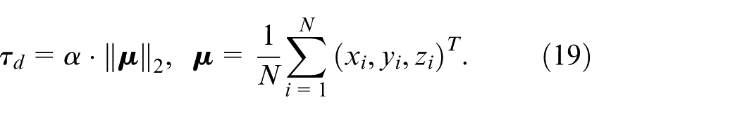
Where
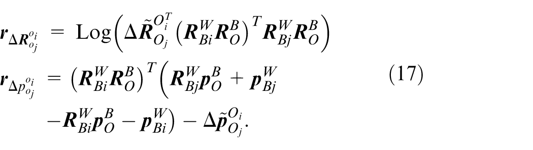
For the ground, we enforce directional constraints to select physically meaningful planes:

Where
Finally, the plane quality metric is defined as the mean absolute distance error of inliers:
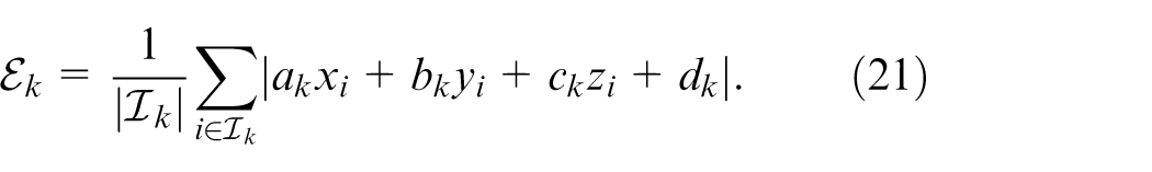
A plane is accepted as a valid constraint factor only when
We have conducted tests on multiple sequences by adjusting
Experiment
To comprehensively evaluate the accuracy and efficiency of the proposed algorithm, APGC-LVIW was tested on the M2DGR-PLUS 34 and M2DGR. 39 The M2DGR datasets contain various challenging urban campus scenarios, such as weakly-textured, open areas, and moving obstacles. The M2DGR-PLUS datasets are the Extension and update of M2DGR, which contain the scenarios of degraded bridge decks, indoor-outdoor transitions, complex street environments, etc. More details of the specifications of all sensors are summarized in Table 1.
Details of benchmark datasets.
indicates that there is no Wheel sensor in the M2DGR dataset.
On these two datasets, APGC-LVIW was compared with several state-of-the-art SLAM methods: LIO-SAM, 17 VINS-Mono, 9 LINS, 40 Odom (The wheel odometry in Ground-Fusion. 34 ), FAST-LIO2, 14 R3LIVE, 25 FAST-LIVO, 29 Ground-Fusion, 34 LVI-SAM. 28 And the computation platform used for tests is a laptop equipped with an Intel i7-12,700H 2.50 GHz CPU and 32 GB RAM.
Accuracy results
Table 2 shows the Root Mean Square Errors (RMSEs) of absolute trajectory error (ATE) for several algorithms on the M2DGR-PLUS datasets. APGC-LVIW performs best in seven out of nine sequences. Benefiting from the proposed multi-modal sensor fusion framework (LiDAR-Camera-IMU-Wheel Odometry), the system effectively integrates heterogeneous sensor measurements, achieving superior localization accuracy in seven out of nine test sequences.
RMSEs of ATE [
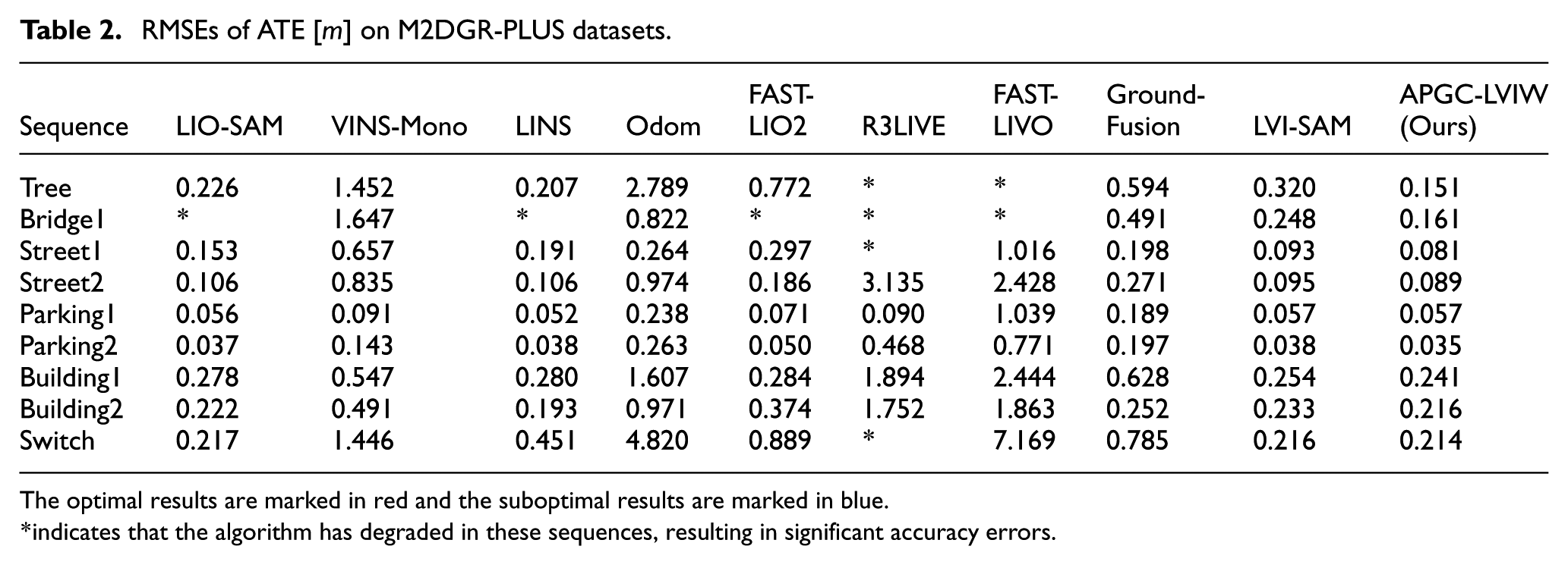
The optimal results are marked in red and the suboptimal results are marked in blue.
indicates that the algorithm has degraded in these sequences, resulting in significant accuracy errors.
Notably, in challenging scenarios such as LiDAR-degraded environments (e.g. Bridge1 sequence) and dense urban campus scenes with heavy tree occlusions (e.g. Tree sequence), conventional LiDAR SLAM and existing multi-sensor fusion methods suffer from performance degradation or even localization failure due to sensor limitations or environmental interference. In contrast, our system, enhanced by wheel odometry integration and the optimization strategy, demonstrates significantly improved robustness and precision in degenerate conditions. Experimental results validate that the proposed multi-modal fusion framework exhibits higher reliability and localization accuracy in complex or degraded environments.
To more intuitively and accurately present the accuracy performance of APGC-LVIW, Figures 2 and 3 show the map construction effects and trajectory estimation results on M2DGR-PLUS datasets. As demonstrated by the mapping comparison in Figure 2 for the Tree and Bridge sequences, our system significantly enhances geometric consistency in multi-sensor state estimation by integrating wheel encoder constraints into the backend factor graph optimization framework. Compared with the LVI-SAM, our approach exhibits superior point cloud registration quality at structural boundaries, such as building walls and vehicles. While LVI-SAM shows noticeable point cloud stratification. And Figure 3 demonstrates that the proposed algorithm achieves higher localization accuracy in local regions compared to the other SOTA algorithms.
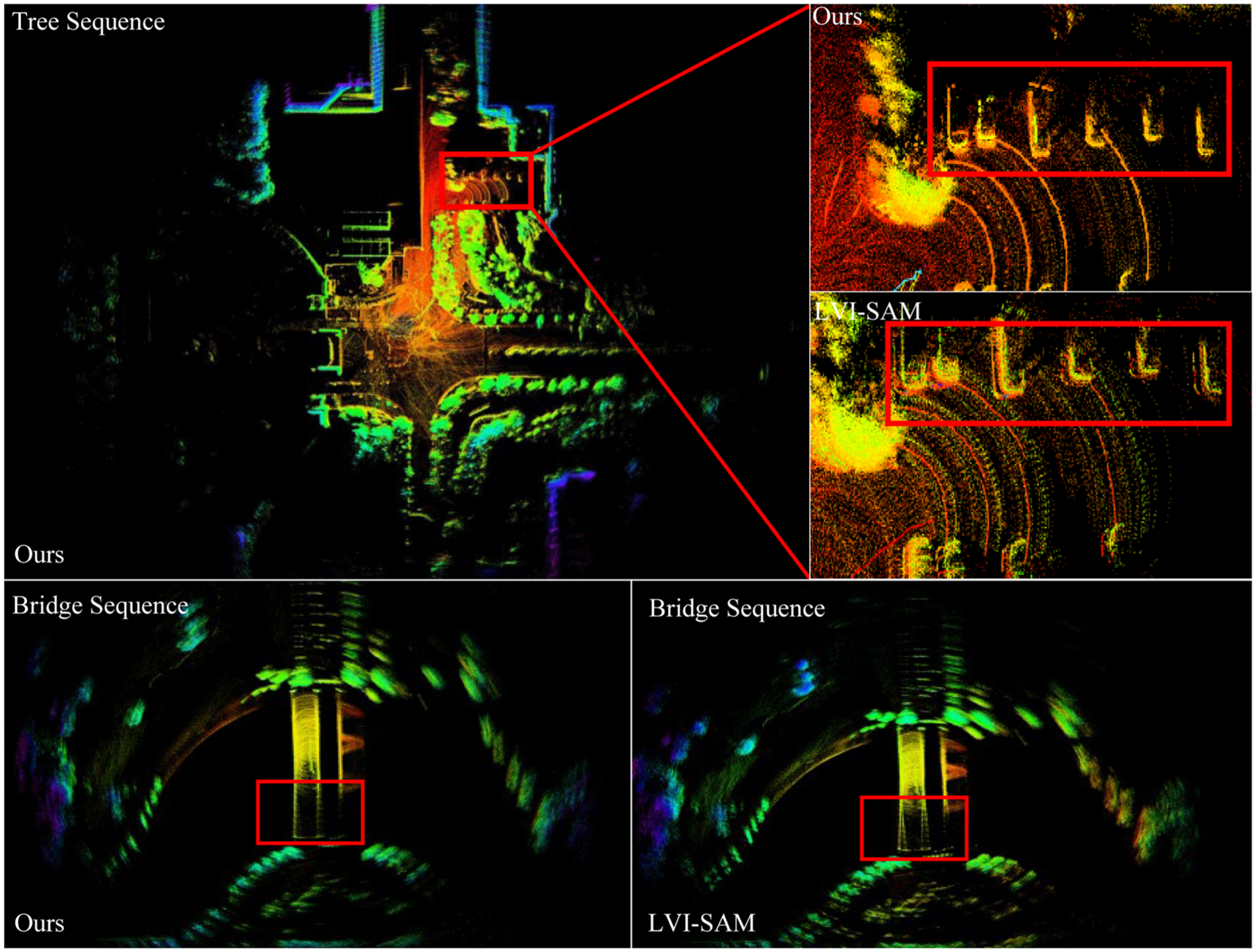
Mapping result of APGC-LVIW on the tree sequence and bridge sequence presented from a bird’s eye view. The partial map highlighted by the red boxes is zoomed in on and compared with the LVI-SAM results.
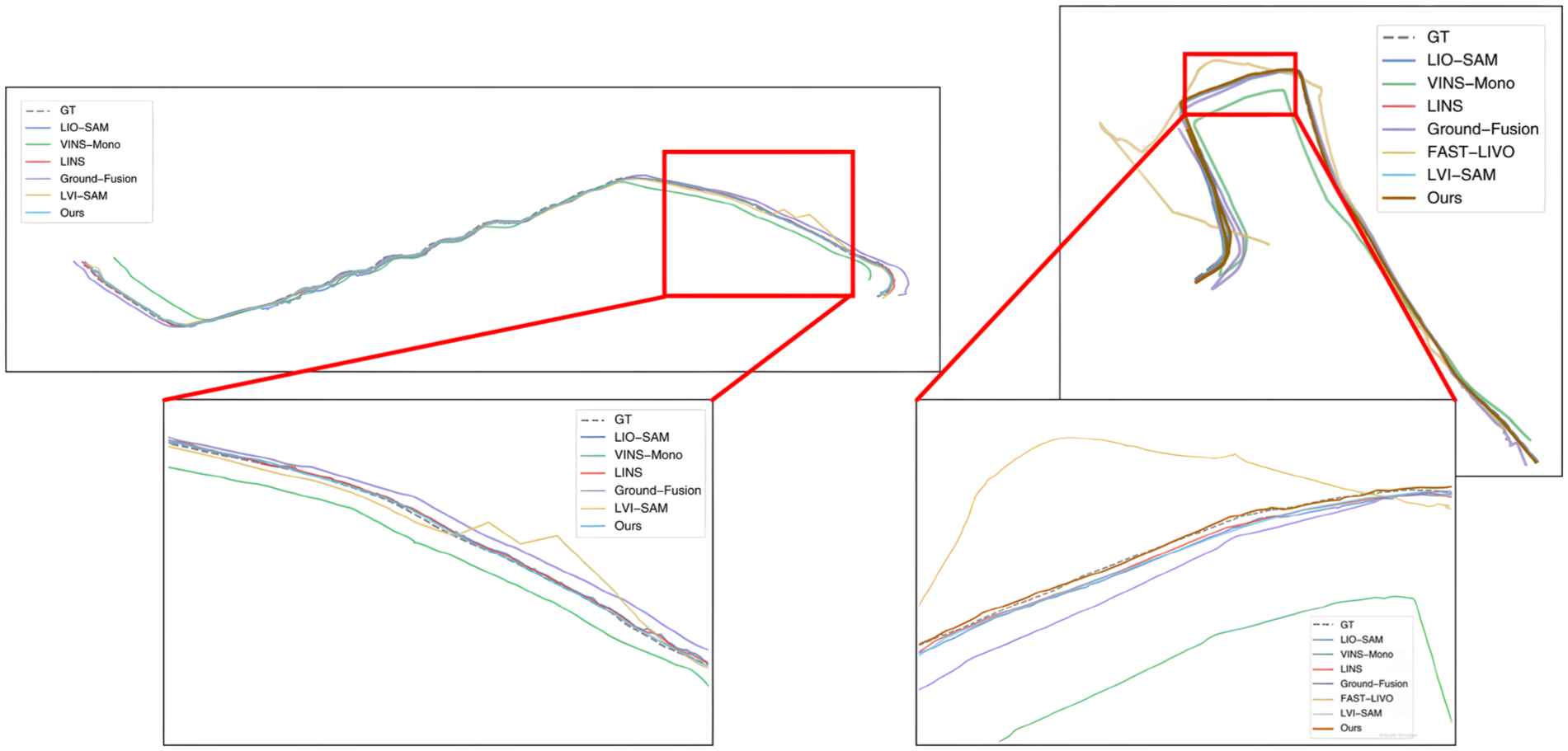
Comparison of trajectories on tree and switch sequence.
In addition, to validate the effectiveness of the proposed plane extraction method based on adaptive dynamic distance thresholds and normal vector consistency verification, along with the integration of planar factors into LiDAR backend optimization, ablation studies on the M2DGR datasets were conducted by incorporating the methodology into the LVI-SAM framework. As shown in Table 3, the proposed method achieves the highest localization accuracy. And the experimental results fully validate the effectiveness of the planar factor proposed in this paper.
RMSEs of ATE [
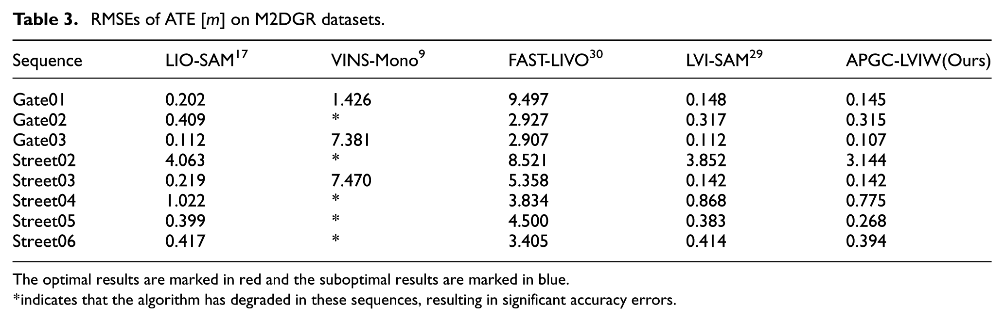
The optimal results are marked in red and the suboptimal results are marked in blue.
indicates that the algorithm has degraded in these sequences, resulting in significant accuracy errors.
Ablation study
To quantify the independent contributions of the two core innovations, adaptive planar factor and wheel encoder fusion, we designed three groups of experiments on the M2DGR-PLUS Tree (LiDAR-degraded, heavy occlusion) and Bridge1 (planar-dominant, degraded deck) sequences. The results are shown in Table 4.
Ablation results on M2DGR-PLUS sequences.
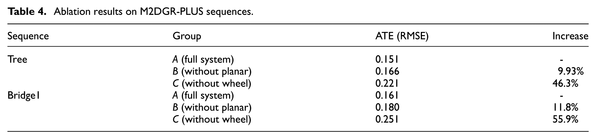
Group B (no planar factor) shows significant ATE degradation: In Sequence Tree and Bridge1, the loss of planar constraints increases local map noise (e.g. deck edge misalignment), leading to 9.93% and 46.3% higher ATE. This confirms the planar factor’s role in suppressing geometric ambiguity. Group C (no wheel fusion) exhibits 11.8% and 55.9% ATE increase: Wheel encoders provide absolute scale to mitigate IMU drift in low-excitation motion, so their removal reduces scale observability. Synergy of the two innovations. The full system (Group A) achieves the lowest error, proving that planar constraints and wheel fusion complement each other.
Runtime analysis
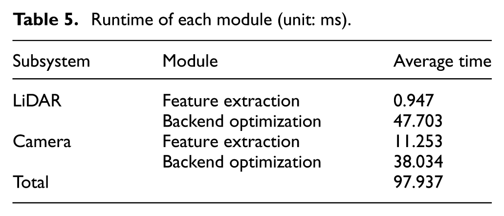
In this section, we evaluate the computation efficiency of our proposed method. Table 5 shows the runtime of each module. When the system receives camera images and LiDAR scans, our algorithm executes each module. Experimental results demonstrate that the total computational time remains at 97.937 ms per frame (including 48.65 ms for LiDAR subsystem and 49.287 ms for visual subsystem), which satisfies the real-time requirement for SLAM systems.
Runtime of each module (unit: ms).
Conclusion
This paper proposed APGC-LVIW, a novel multisensor fusion ground SLAM system that integrates LiDAR, visual, IMU, and wheel encoder data to address the challenges of localization and mapping in complex urban environments. The proposed system achieves high accuracy and robustness by leveraging the complementary strengths of LiDAR and visual sensors through bidirectional initialization and joint optimization. Furthermore, a planar factor based on scene geometric consistency is introduced into the LiDAR subsystem for joint optimization, which enforces geometric consistency on continuous planar structures (e.g. ground and walls), effectively reduces matching ambiguity and suppresses local map noise. This structural constraint not only improves the geometric integrity of the map but also enhances the system’s robustness to dynamic environmental changes. In future research, we plan to conduct more optimization studies on the real-time performance of the system.
Footnotes
Ethical considerations
This article does not contain any studies with human or animal participants.
Consent to participate
Not applicable.
Consent for publication
Not applicable.
Author contributions
Yan Sun conceived and designed the study, developed the codes, and wrote the article. Wanbiao Lin, Liangbo Hu, Bowen Peng and Jinlin Xiong aided in the theoretical formulation. Junjie Zhang assists me in conducting experiments. Lu Zhou and Lei Sun guided the study and provided critical revisions to the article.
Funding
The authors disclosed receipt of the following financial support for the research, authorship, and/or publication of this article: This research is funded by the National Natural Science Foundation of China 62173192 and the Shenzhen Science and Technology Program Foundation JCYJ20220530162202005.
Declaration of conflicting interests
The authors declared no potential conflicts of interest with respect to the research, authorship, and/or publication of this article.
Data availability statement
All used data is contained within the article.