
Abstract
Conventional Direct Torque Control (DTC) is an advanced means of regulating doubly fed induction motors (DFIM) offering superior performance due to its simplicity, high reliability, sensitivity to motor parameters, and improved dynamic response. Nevertheless, the uncontrolled switching frequency of the DTC resulting a high ripple in the torque and the flux which leads to acoustic noise that negatively impacts the control system’s performance. Several DTC control strategies have been developed to overcome the limitations of traditional direct torque control (DTC) by concentrating on torque and flux. In this article, the development of DTC is discussed. The main objective of the paper is to improve the performance of conventional DFIM DTC control, thereby reducing energy losses and improving system efficiency, by using multi-level DTC. In this paper, we compare the performance of two structures of DFIM’s three-level direct torque control and five-level DTC control and present the simulation results. The flux and torque rays are evaluated and compared. The goal is to determine the control that gives the best results.
Keywords
Introduction
The robustness, low cost, efficiency, and ease of maintenance make the two-feed induction motor “DFIM” attractive for many industrial applications. However, this machine presents difficulties at the control level because it represents a nonlinear system, strongly connected, with rapid dynamics and parameters that change over time.1–3 The development of electronic power, with the development of high-speed power components and digital control technology, enabled the use of complex and very sophisticated control structures. This engine must respond effectively to set-point changes (speed, position, torque), which happen in a wide range of operating-point changes.4,5 Takahashi and Noguchi introduced direct torque control in 1986, and Depenbrock introduced it in 1988 for induction machines.6,7 The control technology solves the problem of vector control and exhibits remarkable dynamic performance and good resistance to changes in machine parameters. The purpose of the DTC is to control the torque directly through the application of different voltage vectors from the inverters that supply the machine and thus to get a natural separation between the flux and torque, remove the PWM step, and get the best torque responses. The lack of change frequency control and strong torque pulsating are the main disadvantages of the control strategy. It should be noted that torque fluctuations produce additional noise and vibrations and cause problems with rotating rods. Several techniques can be used to improve the performance of employed to enhance the efficiency of the DTC.8–10
This research aims to compare and analyze the effectiveness of two strategies in enhancing the direct control of the classic torque. The objective is to reduce the oscillations of both the flux and the torque and to provide the machine with a voltage that closely approximates the sinusoidal waveform. We suggest implementing multi-level DTC on the DFIM using dual three-level inverters of voltage, one on the stator side and the other on the rotor side. Subsequently, we want to enhance this technique by incorporating a five-level direct torque control (DTC) system, which consists of two five-level voltage inverters.
Doubly fed induction motor model
The optimal model for analyzing the dynamic characteristics, designing, and implementing the direct torque control of the Doubly Fed Induction Motor (DFIM) is the two-phase model represented by the (α,β) coordinates, as described by the following equations:
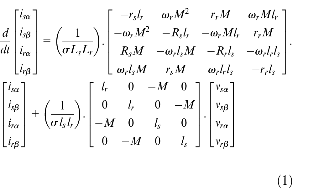
With:
Rs, Rr are stator and rotor resistance.
σ is the Blondel’s coefficient.
ωr is the machine speed
Conventional DTC principle of DFIM
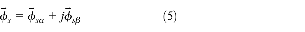
The concept of DTC involves the continuous regulation of both stator and rotor flux, which entails altering the torque provided by the DFIM. The equations provided represent the DFIM flux expressions,6,11,12:
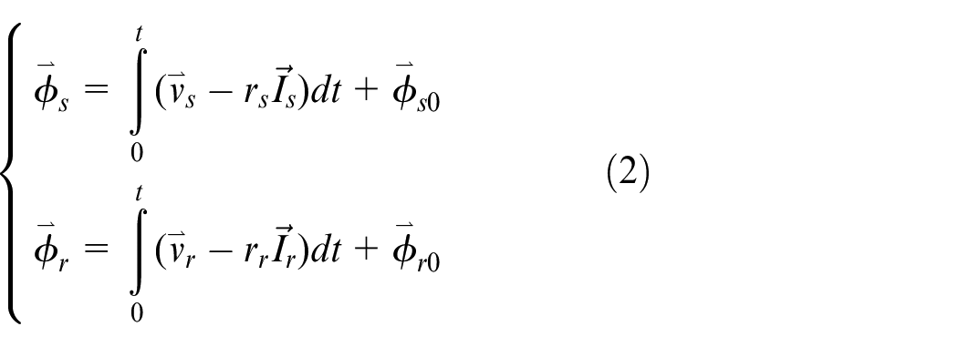
With:
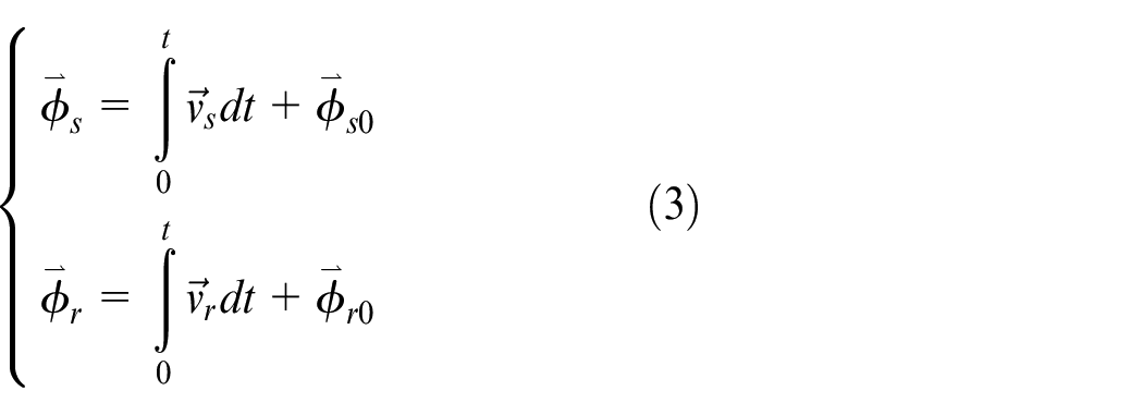
We can disregard the expressions Rs. Is, and Rr. Ir in the relations of the voltages Vs and Vr. Therefore, we can express the stator and rotor fluxes as follows:
Principle of electromagnetic torque control
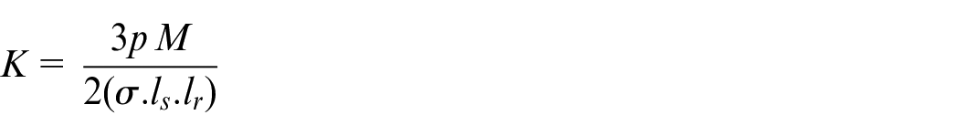
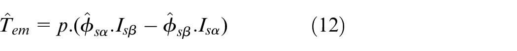
The relationship between the electromagnetic torque and the vector product of the stator and rotor flux vectors can be expressed as follows13,14:
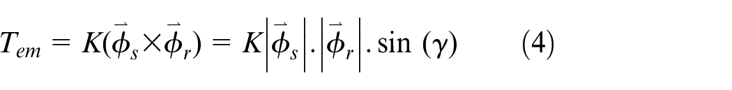
With:
K: is a constant depending on the parameters of the machine.
Estimators
Estimation of stator and rotor flux
The flux can be estimated by analyzing the current and voltage measurements of the machine. Based on the equation,12,15:
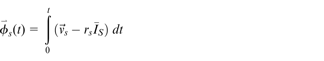
To determine the stator flow vector, it is necessary to calculate its two-axis two-phase components (
With:
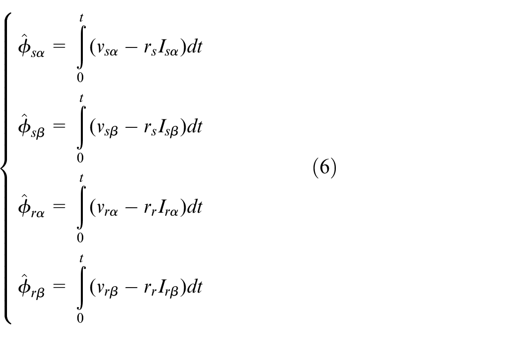
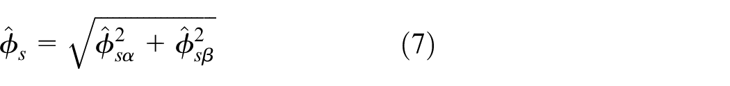
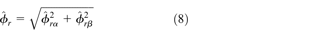
The magnitude of the stator and rotor flow is expressed11,15:
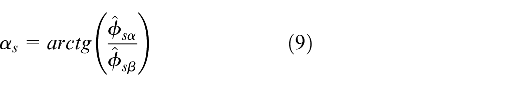
The angle
The stator current vectors

With:
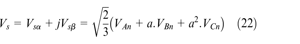
The components vsα and vsβ are obtained by applying the Concordia transformation to the observed input voltages Van, Vbn, and Vcn. The voltages are derived from the input voltage Vdc of the inverter and are determined by the command states (Sa, Sb, Sc):

With:
The inverter’s various states result in a total of 23 = 8 potential possibilities for the voltage vector V, including two zero vectors (V0 and V7) and six non-zero vectors. In Figure 1, the complex plane representation of the eight positions of the vector V generated by a two-level voltage inverter is shown:
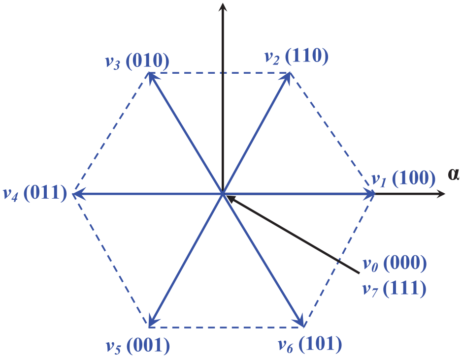
Voltage vectors delivered by the two-level inverter.
Electromagnetic torque estimation
The electromagnetic torque can be put in the following form6,15:
The relationship shown indicates that the estimated torque amplitude is dependent on both the stator flux estimator and the current measurement.
Multilevel inverter
With the development of power electronics and semiconductor components, the technique of multilevel inverters represents an important research area. Multilevel is derived from the three-level inverter. In the present day, there has been a significant development of several multilevel inverter topologies. Multilevel inverters are power conversion systems that consist of a network of power semiconductors and direct current (DC) voltage sources. When appropriately linked and regulated, these inverters can produce a voltage waveform at many stages, with variations in frequency, phase, and amplitude that can be controlled and changed.16,17
The synthesis of the stepped voltage waveform involves the deliberate selection of several voltage levels, which are formed by appropriately connecting the load to different DC voltage sources. This link is established through the precise manipulation of the power semiconductors.18,19
Due to its increased power rating, higher voltages, improved harmonic performance, reduced electromagnetic interference, reduced stress on power switches, and reduced voltage drifts (dv/dt), the multi-level inverter continues to attract industrial and academic attention as one of the first electronic mechanism power conversion for high power applications.20,21
Currently, there are three commercially available configurations of multilayer voltage-source inverters: Neutral Point Clamped (NPC), Cascaded H-Bridge (CHB), and Flying Capacitors (FCs). The initial proposal of the NPC (Neutral-Point-Clamped) topology was made by A. Nabac in 1981. Its purpose was to generate several voltage levels and minimize the amplitude of harmonics injected by the inverter into the load for motor power applications.21,22
Neutral-point-clamped “NPC”
The NPC-type multi-level inverter makes it possible to have a voltage closer to the sinusoid than that resulting from the classic two-level inverter. It also allows, by placing the switches in series, better control of the voltage stresses on the components. 23
Figure 2 illustrates the configuration of the “NPC-type three-level inverter.” The structure consists of three symmetrical arms, with each arm including four switches connected in series. Each switch consists of a bi-controllable switch and a diode positioned from head to tail. Additionally, two diodes are present to enable the attainment of the zero voltage VkM. By utilizing a capacitive voltage divider consisting of filter capacitors C1 and C2 with equal capacities, two secondary DC voltage sources are derived from the primary DC voltage source. Each of these sources provides a half voltage (Vd/2). Subsequently, this configuration establishes a point of equilibrium (M) between the two capacitors.9,24
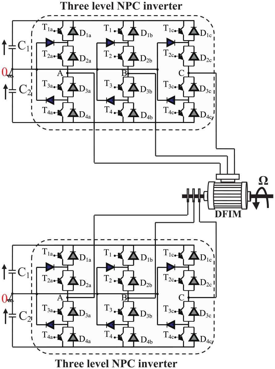
Diagram of a DFIM and its power supply.
The structure of a DFIM fed by two inverters at three levels is given by the Figure 2.
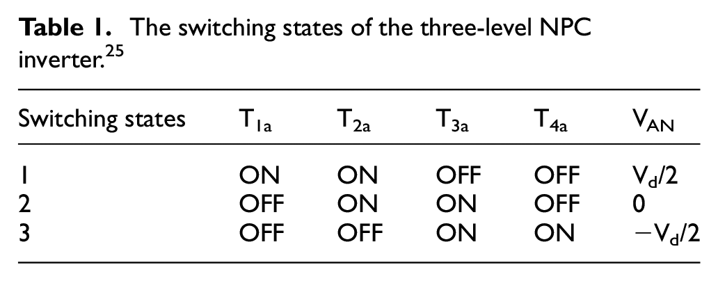
Each arm of the inverter has three switching states represented in Table 1:
The switching states of the three-level NPC inverter. 25
Switch connection function
This function is associated with each switch. It describes its open or closed state. It takes the value “1” if the switch is closed and “0” otherwise. Moreover, we assume in this part that the capacitive divider is balanced (UC1 = UC2 = UC = Vd/2).
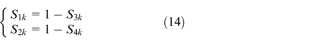
The complementary command for an arm K is then defined as follows:
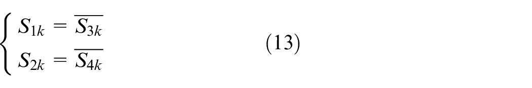
With the additional command thus defined, the connection functions of the switches of arm K can be defined as follows:
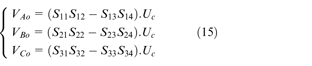
The system of the equation for the voltages A, B, and C of the three-level inverter, relative to the midpoint “o” of the input voltage source, can be expressed using the functions of connecting the switches:
Composed voltages are:
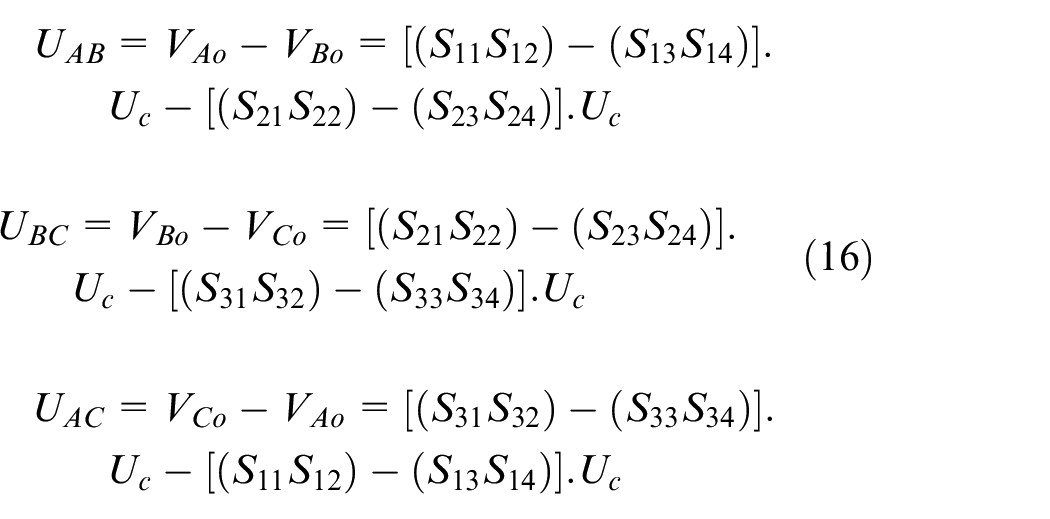
From where:
We deduce the voltages (VA, VB, VC):
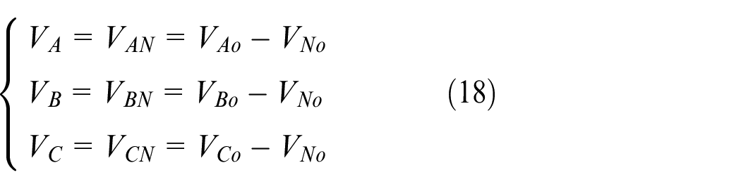
With VN0 the voltage between the midpoint of the DC power supply of the inverter and the neutral point of the load is represented as follows:
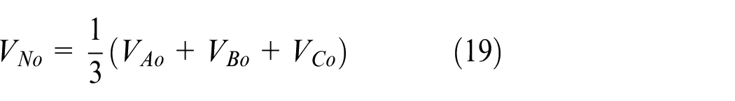
If we assume that the simple voltages of the receiver form a balanced three-phase system, we will have:
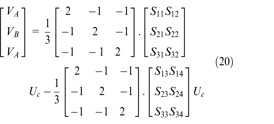
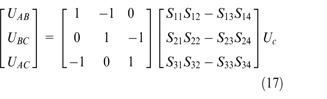
We end up with the system in matrix form, which is written as:
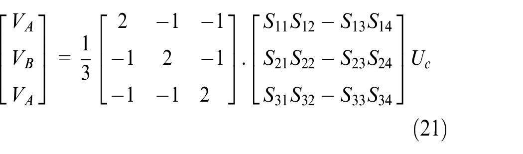
We will use the expressions for simple voltages of the output of the inverter established previously and using the vector form of the voltages write as follows:
With:
There are 27 (33 = 27) possible combinations to control the switches of the three-level inverter. These combinations make it possible to give 19 different values to the voltage vector Vs. 26
As shown in Figure 3, this vector has 18 discrete places in the plane α-β based on the undulator states. They are positioned on two hexagons: twelve on the external hexagon, six on the internal hexagon, and one at the diagram’s origin. Each position on the inner hexagon is produced by two distinct states. These states are called redundant states, the corresponding vectors are called redundant vectors.10,27
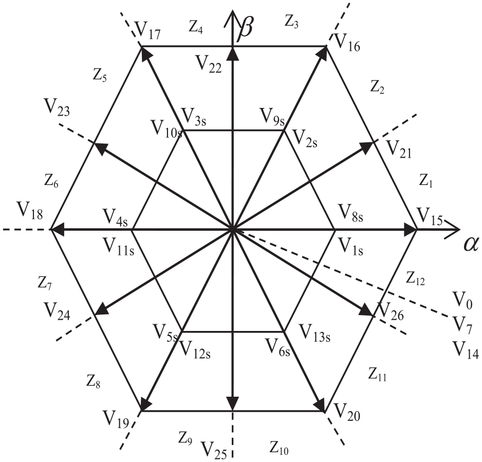
Voltage vectors are provided by the three-level voltage inverter.
DTC algorithm applied to DFIM powered by two three-level inverters
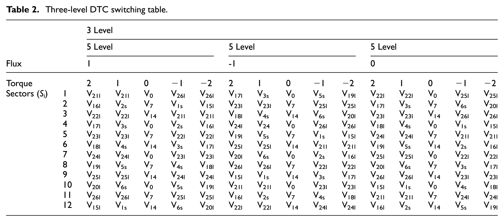
To control the flux and torque directly, DFIM is supplied with two three-level voltage inverters and a new commutation table is developed, taking into account all voltage vectors available at the output of two inverters. The selection of the voltage vector for the static and rotating rotors allows for the increase or decrease of the value of the magnetic torque modulation and the magnetic torque module of the static and rotating rotor (Table 2).
Three-level DTC switching table.
The chosen actual table for the three-level inverter was obtained from the utilization of three-level flux hysteresis comparators and five-level torque hysteresis comparators (Figure 4).
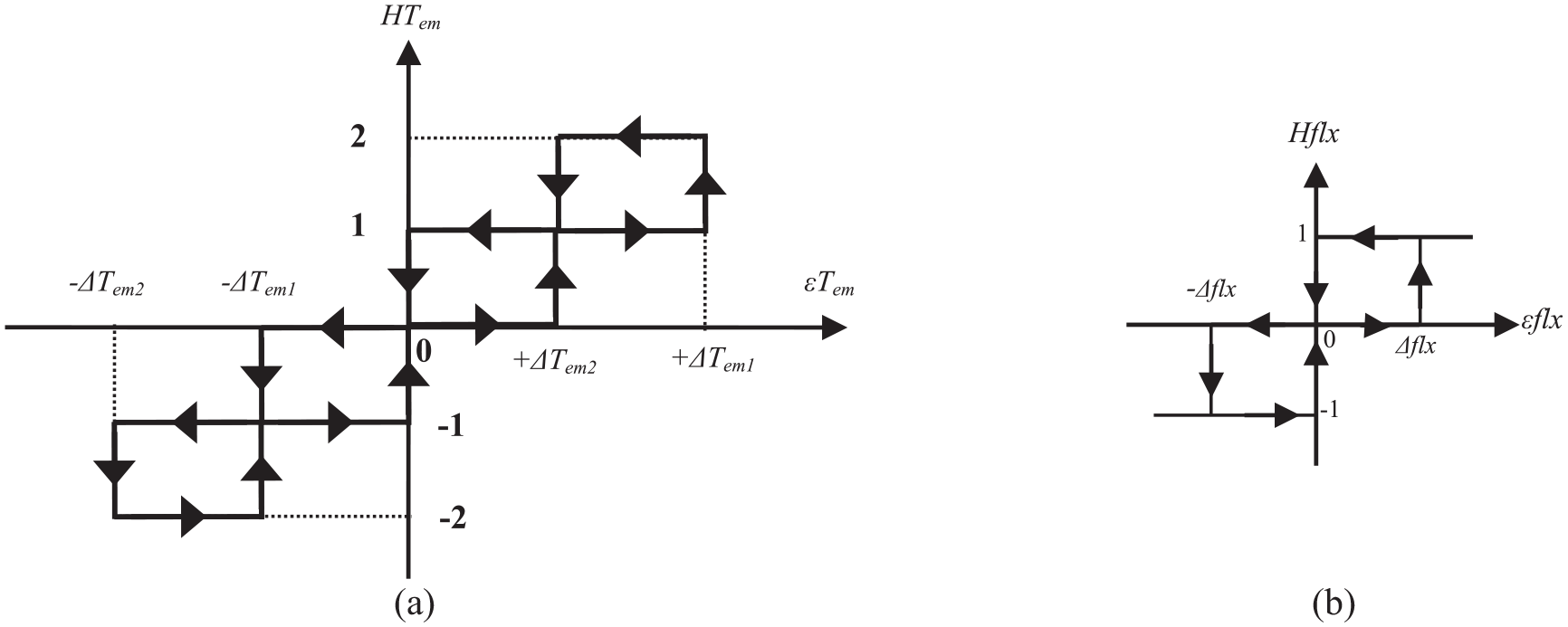
Torque and Flux comparator hysteresis: (a) torque comparator with five levels and (b) stator and rotor flux comparator with three levels.
To improve the DTC-3 level control, we have proposed the DTC-5 level.
Description of a five-level NPC inverter
Figure 5 illustrates the overall configuration of the inverter for the three-phase bridge voltage of the NPC (Neutral Point Clamped) variant, which consists of five stages. Inverter arms consist of three arms, each comprising eight controlled switches and six floating diodes. The regulated switches exhibit unidirectional voltage and bidirectional current, represented by the antiparallel configuration of a transistor and a diode. It is imperative to prevent the simultaneous opening or closing of these switches to prevent a short circuit in the continuous input of the inverter or the opening of the inductive circuit of its load. Each arm is equipped with six floating diodes to ensure the application of varying voltage levels to the output.28,29
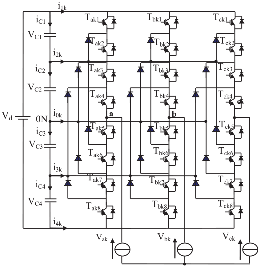
Three phases five-level NPC inverter.
The DC input bus comprises four capacitors, namely C1, C2, C3, and C4, enabling the establishment of a trio of capacitive midpoints. The aggregate direct current (DC) bus voltage is denoted as Vd. In typical operational circumstances, this voltage is evenly divided over the four capacitors, resulting in a voltage of Vd /4 at their respective terminals.30,31
Table 3 shows the different output voltages (Vao) and switch states of the inverter with five levels:
The switching state of the five-level inverter.
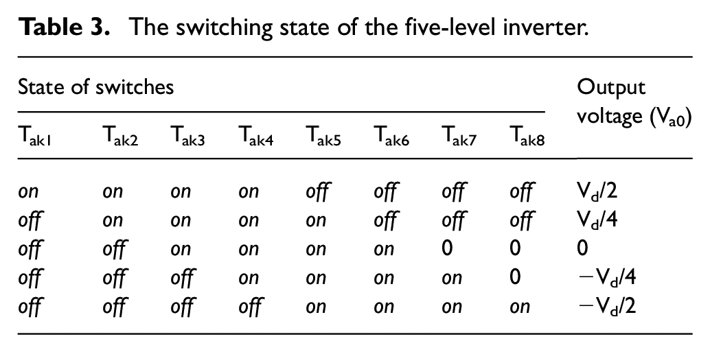
About the DC bus voltage neutral point’s (o), voltages of an output phase are31,32:
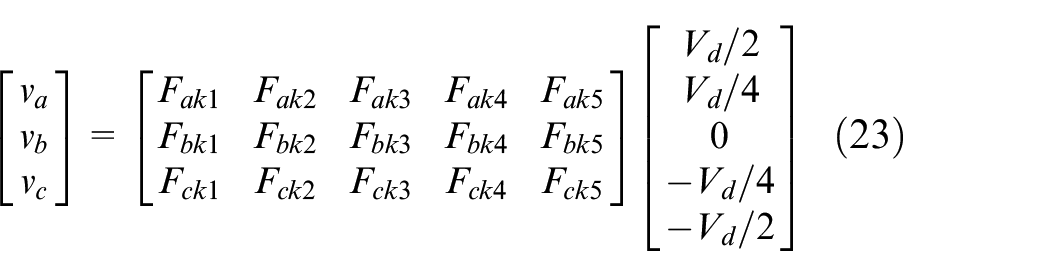
with:
Development of switching tables for the DTCc command at five levels
The vector vo can assume several places inside the plane αβ, contingent upon the states of the inverter. The vector illustration in Figure 6 displays these placements. A total of 60 distinct positions are present, that are evenly distributed among four hexagons, along with a central position within each hexagon. Particular positions can be formed by many duplicate states. The vector vs is formed in places from the external hexagon to the inside hexagon by one, two, three, or four redundant states, accordingly. Five redundant states are used to generate the position of the hexagon center’s, resulting in a zero output voltage. There are a total of 24 positions that have only one redundancy, 18 positions that have two redundancies, 12 positions that have three redundancies, and six positions that have four redundancies. The output voltage vector is divided into six triangular sectors by the 61 locations of the vector diagram.
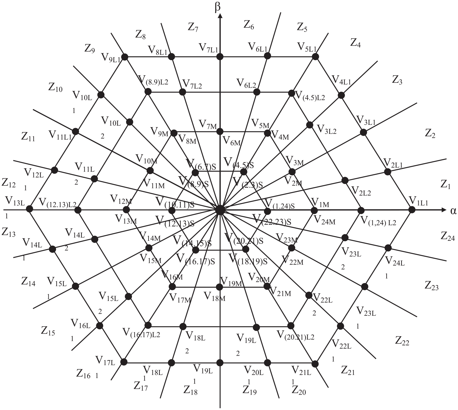
Five-level inverter vector diagram.
The structure of the switchboard is effectively based on the selection of the static and rotary voltage vector applied to enable increasing or reducing the static and rotary current module, as well as the value of electromagnetic torque.
The five-level inverter truth table we have chosen is based on a three-level flux hysteresis comparator and a nine-level torque hysteresis comparator.
Nine-level electromagnetic torque controller
The nine-level torque comparator contains eight bands in the interval (4) to (−4), these bands are symmetrical at the 0 point. The use of a nine-level hysteresis comparator makes it possible to introduce the notion of large and small variations of the electromagnetic torque (Figure 7).
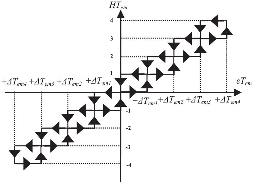
Hysteresis comparators used to control the torque.
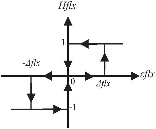
Three-level flux comparator
The three-level hysteresis comparator contains a double band in the interval [1,−1].
The comparator outputs are:
1: corresponds to an increase in flux
0: corresponds to maintaining flux
−1: corresponds to a decrease in flux (Figure 8)
Three-level stator and rotor flux comparator.
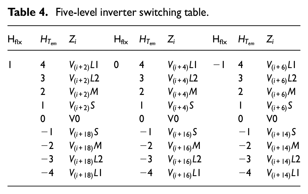
Table 4 provided below provide an overview of the active voltage sequences that can be used to adjust the stators’ and rotors’ flux modulus, as well as the electromagnetic torque, based on the zone of the stator flux.
Five-level inverter switching table.
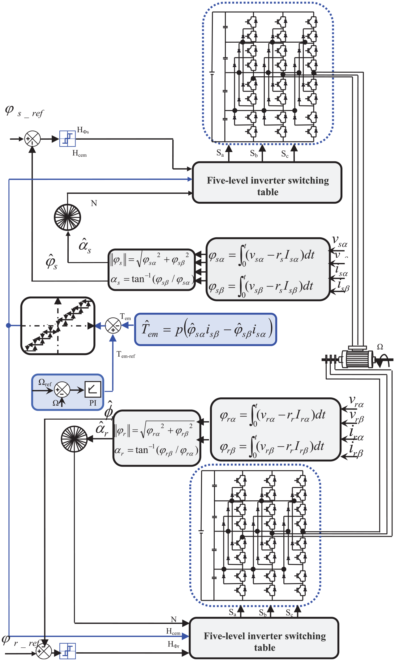
General structure of multilevel levels direct torque control of DFIM
Figure 9 presents the schematic diagram of the multilevel DTC control, which consists of three and five levels, as it is applied to the DFIM. The enhancement of DTC involves the substitution of traditional (two-level) inverters with multi-level inverters, which encompass:
General structure of Multilevel levels of direct torque control of DFIM.
In the first application, we will utilize two three-level inverters to supply power to the DFIM. One inverter will be connected to the stator, while the other will be connected to the rotor. Additionally, we will employ two three-level flux comparators, a five-level torque comparator, and two new three-level switching tables. One inverter will be placed at the stator, while the other will be placed at the rotor.
In the second application, we will employ two five-level inverters to supply power to the DFIM. One inverter will be used to power the stator, while the other will be used to power the rotor. Additionally, we will utilize two three-level flux comparators, a nine-level torque comparator, and two new five-level switching tables. One inverter will be placed at the stator, while the other will be placed at the rotor.
In the two systems studied, we find that the output of each comparator, represented by a sign variable Cflx or Ccpl, directly indicates whether the amplitude of the flux or torque must be increased or decreased to maintain these two quantities within desired hysteresis bands, the switching table gives a direct relationship between Cflx and Ccpl and the switching orders (Sa, Sb, Sc) of the multilevel inverter used and the output parameters.
Simulation results
To validate the proposed algorithms, we present in this part the numerical simulation results illustrating the behavior of the structure of the multi-level DTC of the DFIM, we will carry out a comparison of the dynamic and static characteristics between the 3LVSI-DTC and 5LVSI-DTC.
The following figures represent the simulation results of the DTC control of the DFIM powered by a voltage inverter at three then at five levels for a speed step of Ωref = 150 rad/s, with a load of 10N.m applied between the instants t1 = 1 s and t2 = 2 s respectively.
The simulation results show good behavior of the DFIM despite the variation of the load torque for the two proposed algorithms, we observe that the rotation speed follows perfectly and quickly its reference value with a static error converging toward zero. However, we observe that the rejection of load disturbance was quick with the 5LVSI-DTC compared to the 3LVSI-DTC (Figure 10).
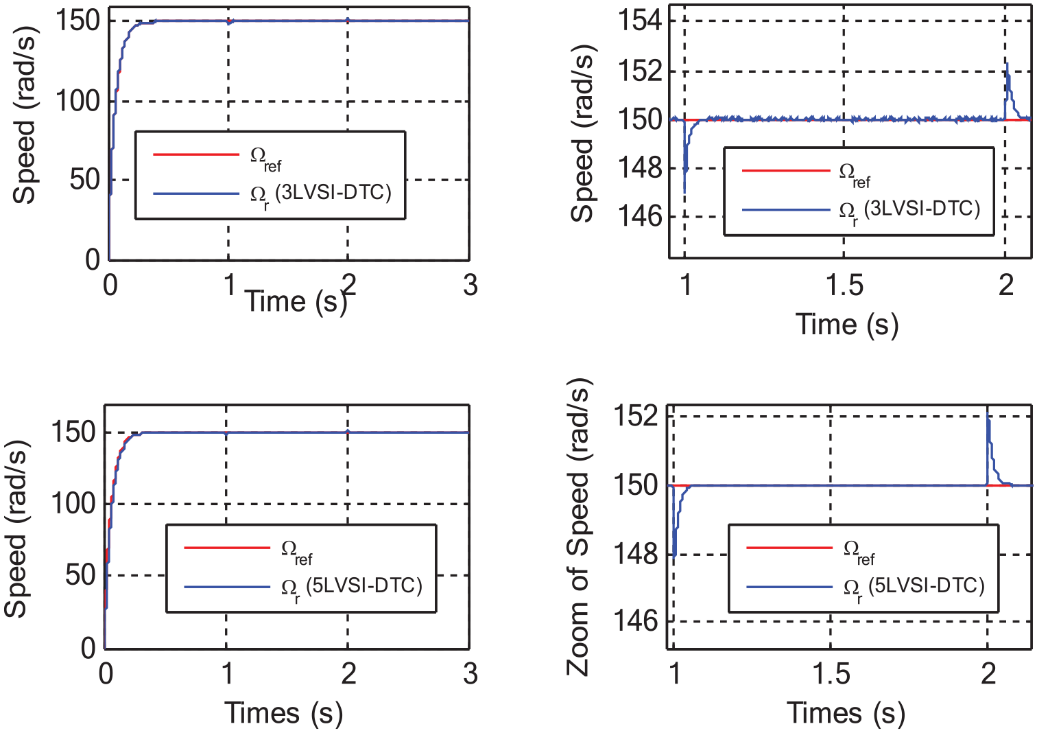
Startup, steady-state speed response, and load application between t = 1 s and t = 2 s: (a) simulation results of DTC using 3LVSIs and (b) simulation results of DTC using 5LVSIs.
The simulation results of the two Figure 11 show that the torque perfectly follows its reference in the established regime for the two proposed algorithms. Figure 11(b) clearly shows that the 5LVSI-DTC control considerably reduces the ripples of the electromagnetic torque, compared to that of the two types of control, the classic DTC and the 3LVSI-DTC control.
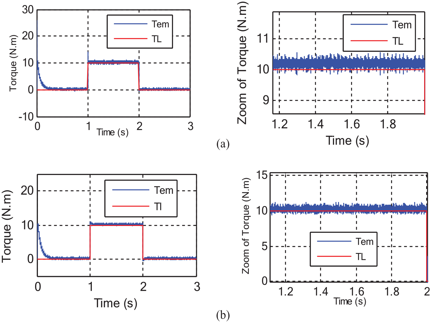
Electromagnetic torque response with load application of 10 N.m between t = 1 s and t = 2 s: (a) Simulation results of DTC using 3LVSIs and (b) simulation results of DTC using 5LVSIs.
Figure 11(b) also shows that in the case of 5LVSI-DTC, good torque dynamics are obtained, with fewer oscillations and overshoot (Figure 11).
Figure 12 demonstrates that the stator fluxes stay at their nominal value without significant overshooting, and the two suggested algorithms exhibit a rapid reaction time. Simulation findings demonstrate the superior performance of 5LVSI-DTC control in comparison to 3LVSI-DTC control. The 5LVSI-DTC control exhibits a significant reduction in flux ripples, which is a noteworthy observation (Figures 12 and 13).
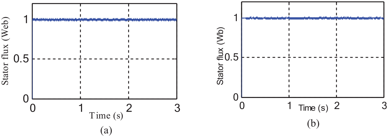
Stator flux magnitude: (a) 3LVSI-DTC and (b) 5LVSI-DTC.
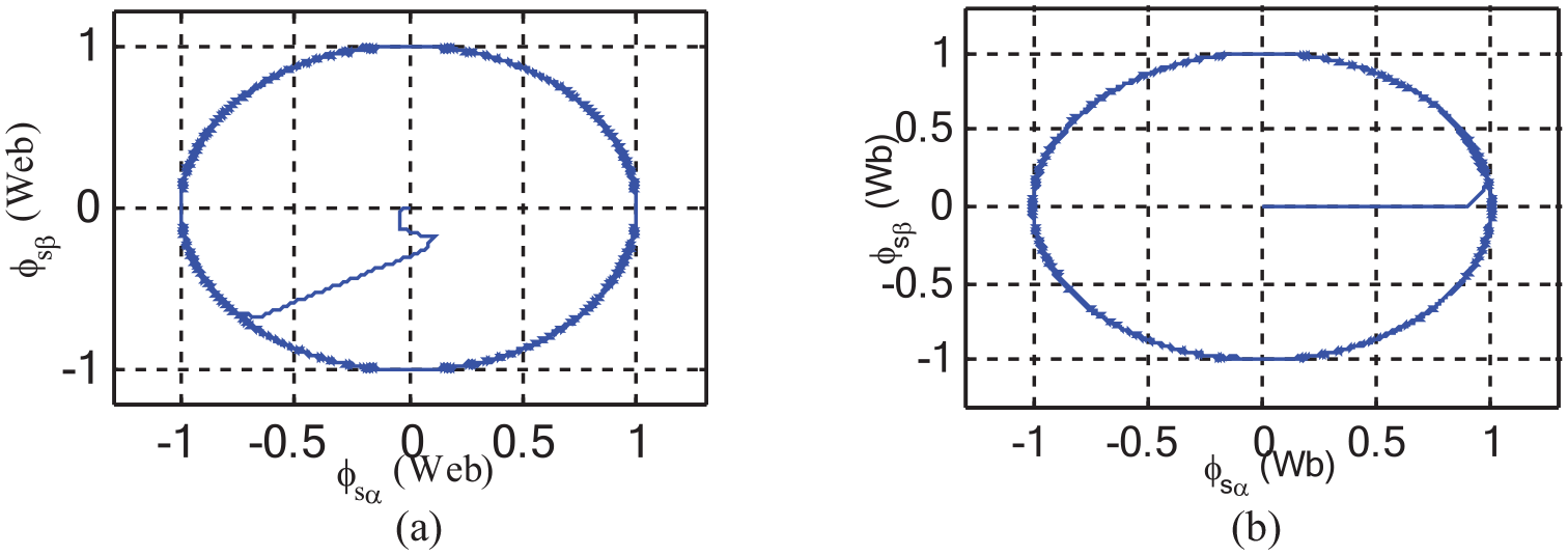
Stator flux circular trajectory: (a) 3LVSI-DTC and (b) 5LVSI-DTC.
It can be noted for the two control methods 3LVSI-DTC (Figure 14) and 5LVSI-DTC (Figure 15) that the flux instructions are always followed by the DFIM for the rotor.
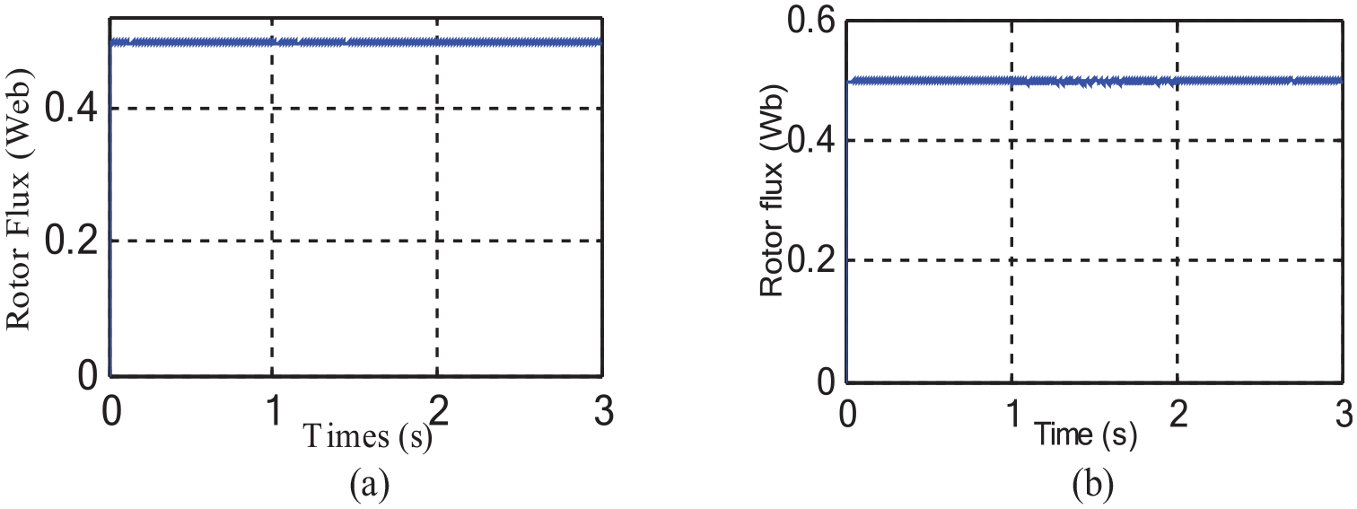
Rotor flux magnitude: (a) 3LVSI-DTC and (b) 5LVSI-DTC.
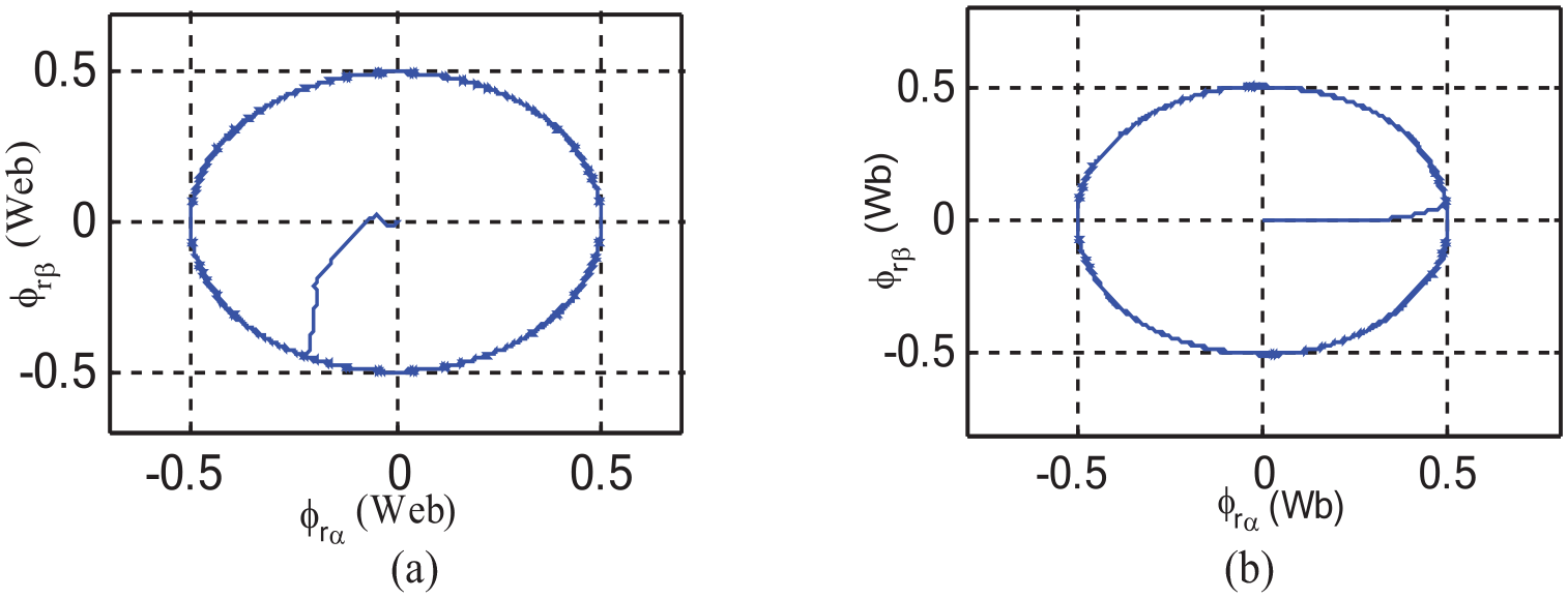
Rotor flux circular trajectory: (a) 3LVSI-DTC and (b) 5LVSI-DTC.
Figures 14(b) and 15(b) demonstrate that the implementation of the five-level inverter results in a decrease in the fluctuations of the rotor flux around its designated value, mostly attributed to the presence of the hysteresis band (Figures 14 and 15).
Figure 16(b) illustrates that the implementation of the five-level inverter results in a decrease in the fluctuations of the stator current. Furthermore, under the set operational condition, the current attains a fully sinusoidal waveform. Additionally, Figure 16 presents the spectrum analysis of the output currents of the machine.
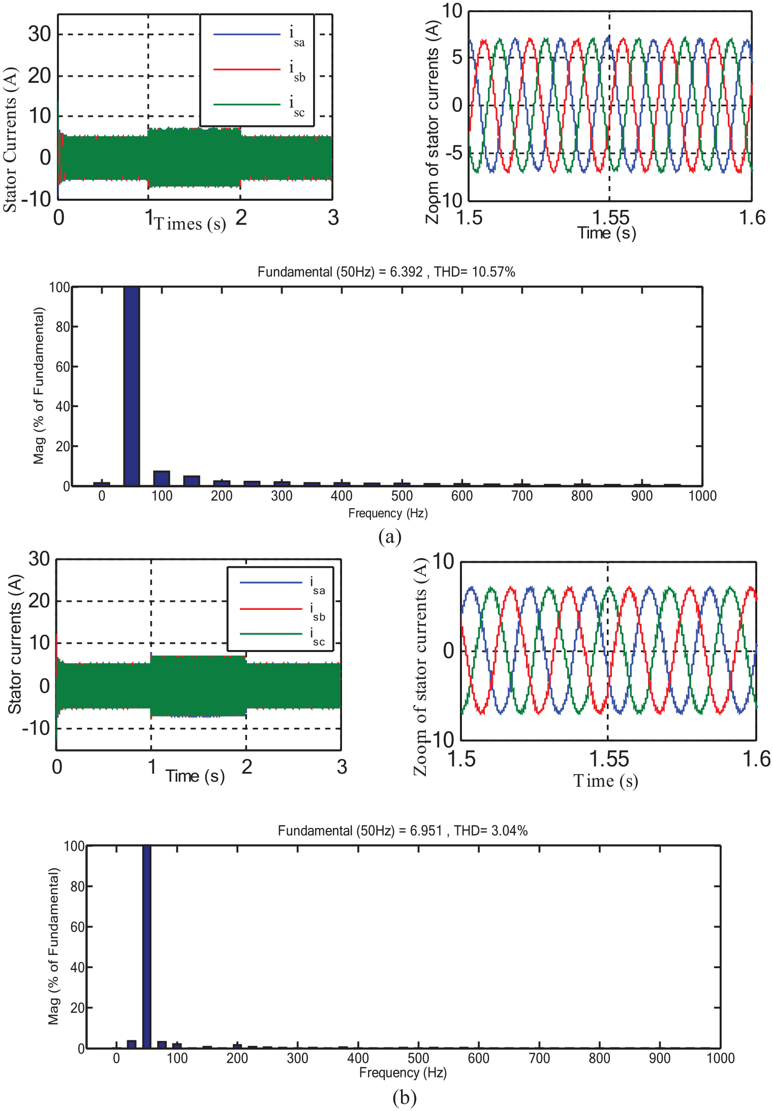
Three phases stator currents: (a) 3LVSI-DTC and (b) 5LVSI-DTC.
Based on the findings shown in Figure 16, it is evident that the harmonic tau of the stator currents in the 5LVSI-DTC (THD = 3.04%) is significantly lower in comparison to the 3LVSI-DTC (THD = 10.57%) (Figure 16).
Likewise, for the rotor current (Figure 17) which has an almost sinusoidal shape with a harmonic tau equal to THD = 5.26% for the 5LVSI-DTC, we conclude that the proposed strategy of the DTC-5 level control considerably reduces A comparison was made between the THD value and that of the DTC-3 level control (THD = 13.93%), which is necessary for a good estimation of the torque.
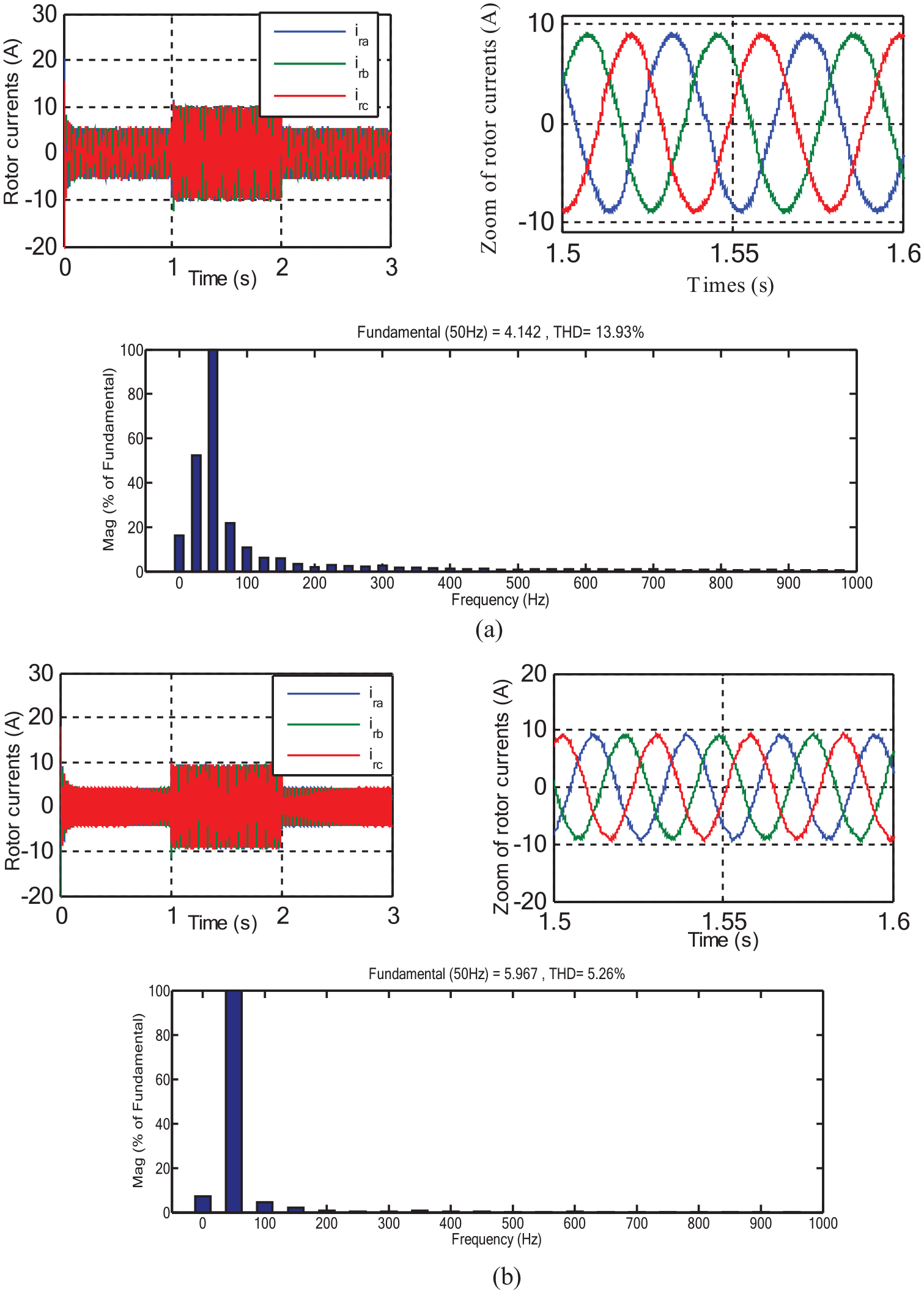
Three phases rotor currents: (a) 3LVSI-DTC and (b) 5LVSI-DTC.
So, the use of multi-level inverters in general makes it possible to improve certain performances of the classic DTC, such as the flux and the torque fluctuations and the switch frequency’s (Figure 17).
Comparative study
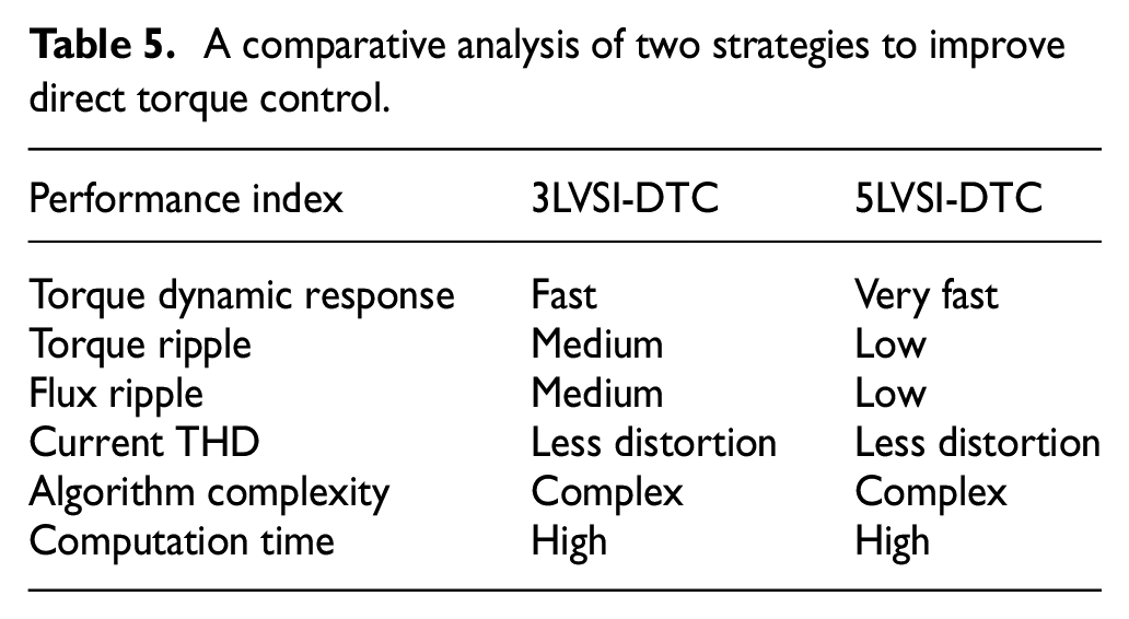
Table 5 below provides a comparative study of the two control methodologies offered to enhance the efficiency of traditional DTC control in a DFIM (Table 5).
A comparative analysis of two strategies to improve direct torque control.
Conclusion
The focus of this study was on the regulation of the DFIM using a DTC control arrangement. The latter is very competitive and attracts the interest of several researchers in their pursuit of achieving a high-performance control system that aligns with contemporary industrial demands. The configuration and theory of the traditional Dynamic Thermal Controller (DTC) utilizing the Takahashi switching table for controlling the DFIM converter have been well explained. The research cited in References30–32 showed that the simulations confirmed the advantageous tracking capabilities of the conventional Direct Torque Control (DTC-C). This is attributed to the regulatory mechanism that relies on the hysteresis of electromagnetic torque and rotor flux. However, it shows significant oscillations in these two parameters as a result of the fluctuation in the switching frequency. This research work proposes two new control tables for the Multi-level DTC of the DFIM. These tables aim to address the limitations of calculation time and enhance the shortcomings of the traditional control. In the first application, the DFIM is controlled using two three-level voltage inverters with NPC structure on one stator side and the other rotor side (i.e. two three-level switching tables). In the second application, the DFIM is controlled using two five-level voltage inverters (i.e. two three-level switching tables). In order to determine the optimal multi-level control approach for the DFIM, it is important to conduct a comparison analysis between two distinct types, namely DTC-3 levels and DTC-5 levels. The simulation results demonstrate that the implementation of DTC-5 level control significantly mitigates the fluctuations in electromagnetic torque, stator flux and rotor, and THD values of stator current and rotor, in comparison to the two control types: traditional DTC and DTC control. There are three levels. The simulation findings demonstrate that employing the five-level inverter significantly decreases current ripples during machine startup, resulting in lower peaks compared to the three-level inverter.