
Abstract
The growing global demand for renewable energy has increased the need for efficient and reliable control systems in photovoltaic (PV) applications, ensuring optimal energy extraction and stable grid integration under varying environmental conditions. This paper conducts a detailed analysis of both simulated and practical implementations of a system that integrates a photovoltaic (PV) panel, a DC-to-DC boost converter, and a DC-to-AC inverter. The control of the boost converter is handled by an Intelligent Artificial Neural Network (IANN), and the inverter operation is managed by a Fuzzy Logic Controller (FLC). Notably, the FLC achieves a Total Harmonic Distortion (THD) of just 1.63%, substantially better than the 2.56% THD observed with the MPC algorithm, and it maintains stable output voltage even under variable shading conditions, outperforming both PSO and P&O methods. Extensive simulations carried out in MATLAB-Simulink provide a comprehensive analysis and discussion of both the simulation and experimental results. Furthermore, the development, implementation, and evaluation of electronic circuits (PCB boards) demonstrate their effectiveness in facilitating the seamless integration of PV systems with the electrical grid. The process-in-the-loop (PIL) structure employed in the programming phase significantly aids in debugging, thus enhancing the operational efficiency of the system and simplifying the resolution of software issues. The proposed hybrid technique shows superior results in various performance metrics, achieving a maximum power efficiency of 99.99%, a relative error of 0.000001, and a minimum tracking acceleration of 0.013 s. This study showcases the latest developments in control strategies, enhancing grid compatibility and overall system performance in photovoltaic applications.
Keywords
Introduction
The global demand for electricity must be increased in the present times. Factors such as population growth, economic expansion, the rapid depletion of fossil fuel-based energy reserves, and the swift escalation in energy consumption collectively contribute to this heightened energy requirement. This transition is motivated by the urgency to lower carbon emissions and minimize the environmental impact of traditional energy sources. 1 Consequently, the next step involves exploring alternative sources of power generation. Conventional sources of energy are becoming scarce, necessitating the adoption of renewable energy solutions to bridge the supply-demand gap. As a crucial solution to the impending depletion of traditional energy resources, renewable energy has gained significant prominence 2 A prominent option among these is renewable energy, which has the potential to provide energy without adverse environmental repercussions. 3 Advancements in power electronics switching technology have seen notable growth, particularly in the development of power systems centered around Renewable Energy Sources (RES) like photovoltaic (PV) systems, fuel cells, and wind energy systems. Among these, PV systems have emerged as the fastest-growing green energy solution globally, demonstrating efficacy in capturing renewable energy that is not only more cost-effective but also environmentally sustainable. 4 To achieve desired current and voltage levels, specific arrays of PV cells are configured in series and/or parallel arrangements. In scenarios where the voltage output from the solar panel falls short of the required level, a boost converter is applied along with a maximum power point tracking (MPPT) algorithm. This synergistic combination serves the purpose of elevating the DC voltage to the necessary magnitude, ultimately serving as the input voltage for the inverter circuit. The core aim of Maximum Power Point Tracking (MPPT) is to analyze the current and voltage output of the PV panel, conducting computations to accurately locate and maintain the maximum power point amidst variations in temperature and irradiation conditions. 5 Various algorithms are at hand to facilitate this process, encompassing Perturb and Observe (PO), incremental conductance (INC), parasitic capacitance, and constant voltage, among several others such as The neuro-fuzzy controller is used to regulate the duty cycle of the boost converter. 6 Among these options, the Perturb and Observe algorithm stands out due to its straightforward nature, rendering it the algorithm of choice for most applications. 7 The fluctuating solar energy in a PV system is turned into constant DC power, and an inverter that is connected to the grid is required to create the alternating electrical power that feeds the AC bus. 8 Square wave inverters or quasi sine wave inverters make up the majority of commercially viable uninterruptible power sources. Electronic devices controlled by these inverters may be harmed by the harmonics material. 9 Pure sine wave inverters cost too much to be practical. Power electronics applications like motor drivers, UPSs, and green energy systems frequently employ the adaptable tool PWM. The technique of Sinusoidal Pulse Width Modulation (SPWM) stands out due to its consistent amplitude pulses with varying duty cycles for each phase. The commonly adopted method for generating this signal involves a comparison between a carrier signal (sinusoidal waveform) and a reference signal (triangular waveform). 10 The microcontroller is responsible for generating a PWM signal that regulates the gate drive voltage. Utilizing the Arduino microcontroller is particularly advantageous due to its affordability, simplicity, and adaptability for real-time control of operational algorithms without necessitating structural hardware modifications. 11 This inverter can be utilized either independently or as an integral component of a grid-connected system. As a result, the field demonstrates extensive coverage, driven by a substantial global demand for electrical resources. In recent years, numerous projects have surfaced with the goal of harnessing energy generated by PV systems to support the existing utility grid or function as standalone systems. In the year 2015 12 a system was formulated with the objective of optimizing the integration of a single-phase PV inverter through the utilization of dual boost technology. This process involved converting DC 24V into 220V AC, employing a fixed modulation index of 0.8. Notably, the inverter exhibited a performance level approaching 99% efficiency. These outcomes underwent validation using MATLAB software. Further enhancements were explored, including the adjustment of the modulation index value and modifications to the configuration of the filter circuit. These refinements have the potential to lead to substantial efficiency improvements. During the year 2018 13 a simulation and experimental testing were conducted on a single-phase alternating current power generated by a PV cell. The power circuit was designed to generate a sinusoidal output utilizing a boost converter in conjunction with an H-bridge inverter. The ANN technique is applied to generate sinusoidal pulse width modulation (SPWM) for a bidirectional AC–DC inverter, with the entire algorithm simulated in MATLAB Simulink. 14 Similarly, in 2019, a two-level DC-AC boost inverter dedicated to photovoltaic applications underwent simulation and experimental validation. 15 This comprehensive system, consisting of the boost converter and the DC-AC inverter, necessitates the use of four basic switches within an H-bridge inverter configuration. As there is no requirement for an additional switch in the boost converter, the overall system efficiency experiences an improvement. In16,17 a three-phase voltage source inverter was employed, utilizing a PV circuit as the input source for regulating the speed of an induction motor. The results obtained during the dynamic operation of the induction motor demonstrated commendable performance. In18,19,20 a single-phase PV inverter designed for standalone applications, operating without the need for battery storage, was conceptualized and simulated. This proposed inverter has demonstrated the capability to consistently generate a pure sine wave voltage and current, even under varying weather conditions or load fluctuations. Additionally, it has achieved a favorable Total Harmonic Distortion (THD) content in the output current waveform under different solar irradiation levels.
This study involves the simulation and practical implementation of a single-phase PV power circuit. The system incorporates a boost converter utilizing an Artificial Neural Network (ANN) algorithm, alongside an H-bridge inverter employing Sinusoidal Pulse Width Modulation (SPWM). This study is an extension of a previous exploration, expanding upon it by incorporating a sophisticated ANN algorithm for Maximum Power Point Tracking (MPPT). The aim is to achieve a comprehensive understanding of constructing a modern PV system. The structure of this paper is organized as follows: Section “Introduction” presents a detailed description and model of a photovoltaic system. Section “Micro grid control modeling powered by PV system” outlines the design of the DC-DC boost converter architecture, followed by a more comprehensive elaboration of the ANN algorithm in Section “Modeling of DC to DC boost converter.” Finally, Section “Maximum power point tracker based on intelligent artificial neural network” covers the practical implementation of the system, along with the presentation of relevant results from simulations in MATLAB-Simulink and implementation on the DSP Launchpad F28379D.
Micro grid control modeling powered by PV system
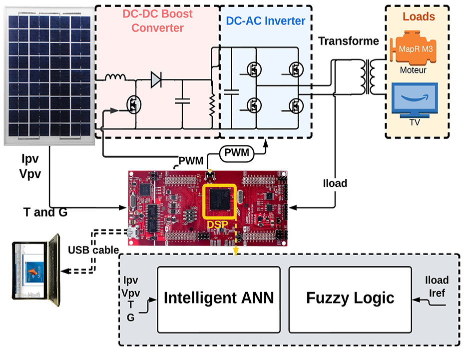
Illustrated in Figure 1 is the fundamental block diagram representing the power PV system introduced in this research. This configuration comprises key components: a solar PV panel, an SPWM inverter, a DC-DC power converter equipped with an MPPT controller, and a load. The MPPT operation for the solar panels involves utilizing the PV current and voltage signals. Linking to the PV module is the boost circuit, which generates an output voltage aligned with the MPPT level.
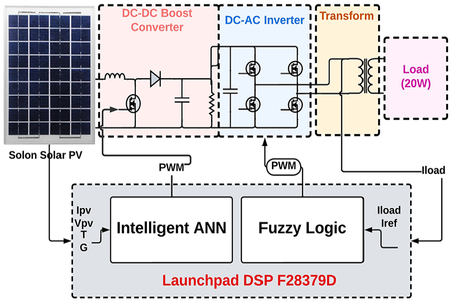
Monophase microgrid based in PV system.
The input of the single-phase inverter is interconnected with the terminals of the boost converter. To achieve optimal voltage and current levels, the boost converter undergoes control and activation through the ANN algorithm.
To achieve the required AC voltage and frequency, the inverter power circuit is set into motion. PV cells can be likened to extensive p-n junctions akin to diodes. An equivalent circuit for the PV cell, as displayed in Figure 2, serves to illustrate a model that captures the cell’s traits. The formulation of a mathematical model for a PV cell is achievable through MATLAB/Simulink. The V-I characteristics of the PV cell, as illustrated in Figure 3, are defined based on the PV current equation outlined below.21,22
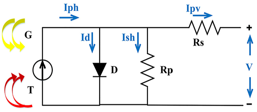
Equivalent circuit of PV cell.
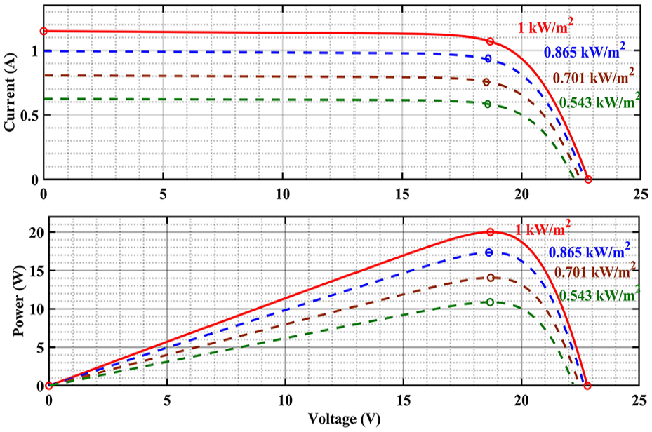
Characteristic of PV panel used.
Modeling of DC to DC Boost converter
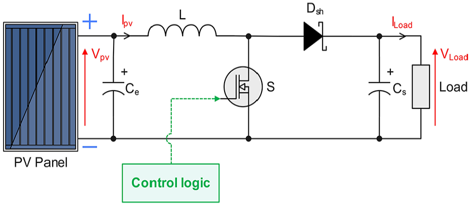
Frequently employed as an intermediary between the load and the PV panel, the boost converter circuit serves as a vital interface. In this configuration, the PV output is harmonized with the load to achieve maximum power (MP). The converter works by transforming the magnitude of input direct current voltages into variable direct current voltages. Depicted in Figure 4 is the power circuit configuration of the boost converter employed in this investigation. This elementary boost converter consists of components like a switch, diode, capacitor, and inductor. Regulation of the output voltage generated by the boost converter circuit hinges on the utilization of the duty ratio.

where:
with the approximate ripple current in the inductor as 40%:

Equivalent circuit of DC-DC boost converter.
The filter capacitor should provide the load with the output DC while the diode is off.

where:
the input capacitor, accounting for constraints imposed by ripples.
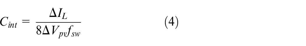
where:

Maximum power point tracker based on intelligent artificial neural network
Convolutional Neural Networks (CNNs) are a type of deep learning model primarily used for analyzing visual data but are also effective in various optimization tasks. CNNs consist of multiple layers, including convolutional layers that extract features from input data using filters, pooling layers that reduce the dimensionality of data, and fully connected layers that make predictions based on the extracted features. Their ability to automatically learn spatial hierarchies and patterns makes CNNs highly effective in tasks such as image recognition and feature extraction from complex datasets. In recent years, deep learning techniques have shown significant promise in improving model generalization and regularization in various applications (MR-DCAE). 23 For the enhancement of PV panel utilization, the implementation of the MPPT approach is integral. Given that the power output from these panels remains subject to fluctuations due to environmental factors like temperature and irradiance, this method plays a pivotal role in facilitating the extraction of the highest attainable power from the PV source to the load. A diverse range of techniques have been devised to optimize solar energy generation, including constant voltage, open voltage, Perturb and Observe (PO), incremental conductance, fuzzy logic control (FLC), and neural network (NN) methodologies.24,25 These strategies exhibit distinctions in terms of complexity, cost, efficacy, tracking speed, prevalence, hardware requirements, and other factors. A precise evaluation of the costs associated with these MPPT algorithms can be accomplished by comprehending the control system’s methodology (analog or digital), the quantity of sensors employed, and any supplementary power components. This analysis is conducted while maintaining all other expenses (power components, electronic elements, boards, etc.) constant across the entire system. 26
The proposed MPPT controller such as depicted in Figure 5, built upon artificial neural networks, operates on a principle similar to the perturbation and observation (P and O) method. In this method, the duty cycle is adjusted either up or down depending on the sign of (dP/dV). The central goal of the ANN is to rapidly ascertain the Maximum Power Point (MPP), differentiating it from other techniques. Our project utilizes an Intelligent Artificial Neural Network (IANN) to efficiently track the MPPT, optimizing power output by learning and adapting to the complex, non-linear behavior of solar panels under varying conditions. Meanwhile, a Fuzzy Logic Controller (FLC) manages the inverter, ensuring stable and high-quality AC power conversion. Together, this combination significantly enhances overall system performance and efficiency.
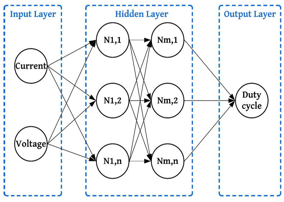
Illustration depicting a multilayer feed-forward neural network.
Fuzzy logic controller (FLC) for a single-phase inverter
Moreover, by modifying their multi-rule variable, they are very useful in responding to the linear and non-linear characteristics of a system. 27 The basis of the fuzzy system is a set of knowledge-based rules; most of the rules in the knowledge base are If-Then rules, which make up a significant portion of fuzzy logic controllers (FLC). 28 When designing an FLC, it is crucial to use variables as inputs that represent the system’s dynamic performance. This technique is very good at dealing with non-linear systems because it is composed of three essential parts: fuzzification, inference, and defuzzification. 29
The process of “fuzzification” makes it possible to convert physical input variables into fuzzy sets. In this investigation, two inputs are used: the error Error(S) and the change of error


Defuzzification: Converting the fuzzy output to a numerical value.
The presented Figures 6–8 depict the membership functions of the fuzzy logic controlling of the inverter Error, variation of
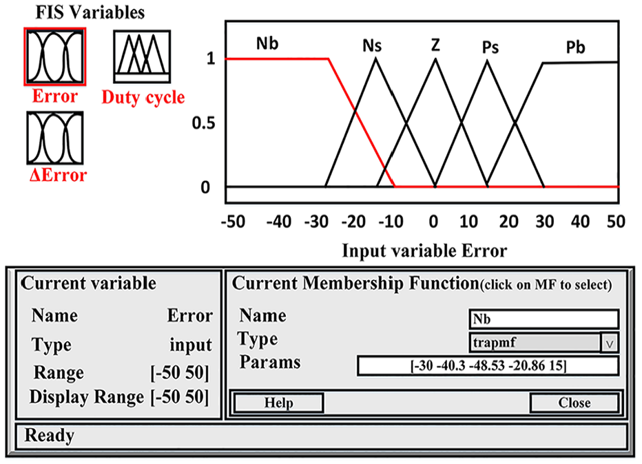
Membership function of input error.
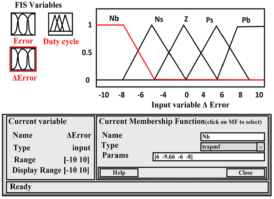
Membership function of input Variation of error.
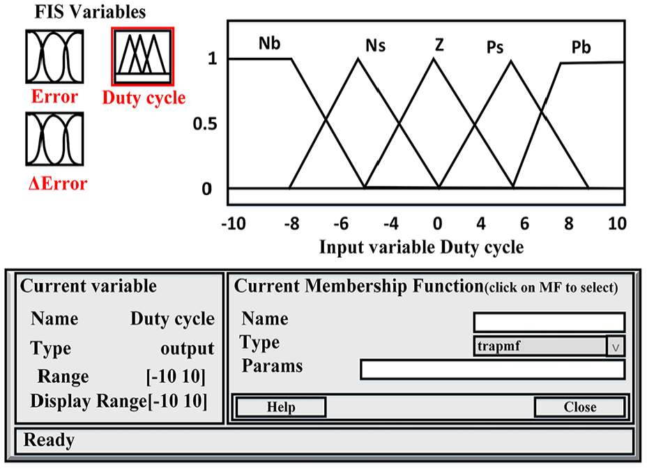
Membership function of output.
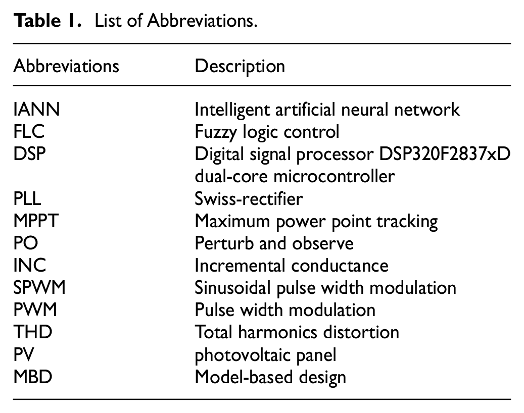
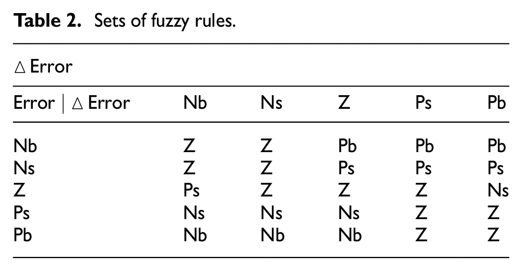
All rules or decision variables are covered by inference, and as the Table 1 illustrates, a logical link between the inputs and the output is established throughout the membership rule definition process. The inverter’s Fuzzy Logic Controller (FLC) relies on the comparison between the load current (
List of Abbreviations.
Sets of fuzzy rules.
Implementation of our proposed system
Process in the loop
In this context, when employed adeptly, model-based design (MBD) processes offer a cohesive design environment. This allows developers to utilize a single collection of models throughout the entire lifecycle for tasks such as validating requirements, analyzing data, visualizing models, testing and validating, and finally deploying the product, whether through automated code generation or not. Model-based design functions as a framework for virtually prototyping embedded software. The evolution of MBD has been driven by the aim of surmounting the challenges and intricacies commonly encountered during the design lifecycle of embedded software for closed-loop control systems or digital signal processing (DSP) applications. The primary objective of Processor-in-the-Loop (PIL) is to bridge the divide between the controller model design conducted within simulation software and the actual execution of controller code on the designated target. The PIL methodology, depicted in Figure 9, serves the purpose of detecting errors that might originate within the compiler. Additionally, the PIL environment facilitates the debugging of algorithm functionality and the assessment of numerical performance on embedded microcontrollers or DSPs. Moreover, the PIL configuration provides valuable metrics concerning the software system, such as memory consumption and execution duration. These measurements can then be employed to refine controller functions in the simulation environment and enhance the embedded hardware design at an early stage of the design process.
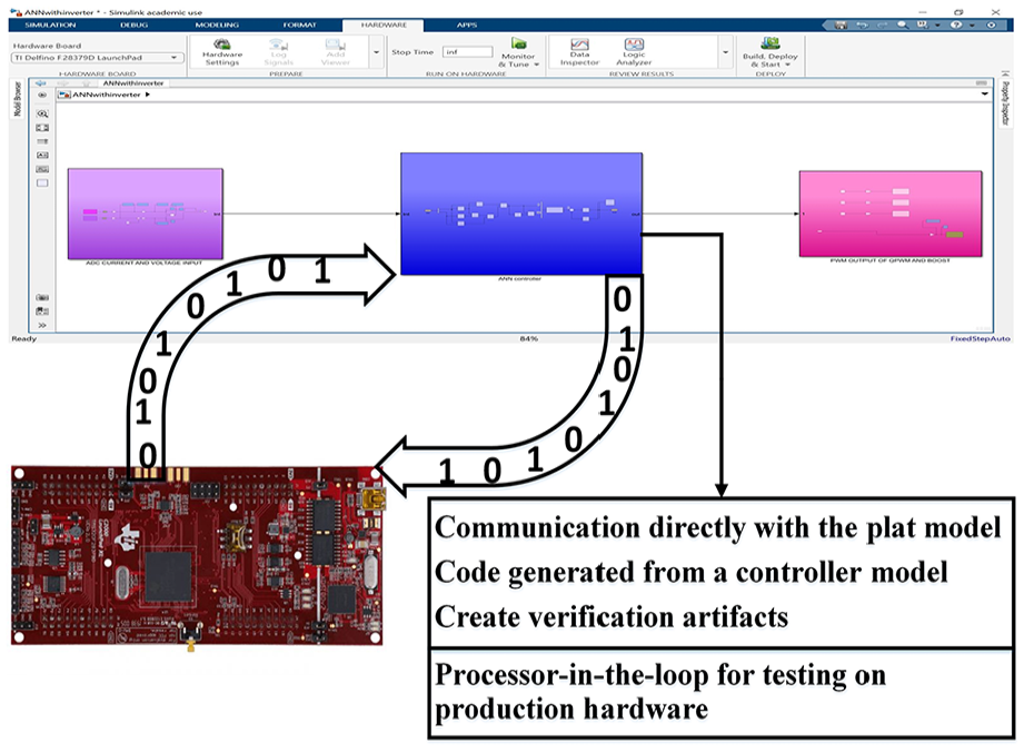
Processor and loop (PIL) implementation.
The emphasis of this system is directed towards utilizing Processor-in-the-Loop (PIL) to acquire authentic measurements from sensors employed for voltage and current measurements. This aims to rectify errors within the ANN algorithm, ultimately serving to bridge the disparity between the controller model design conducted within simulation software and the live execution of controller code.
Test bench
The existing conversion sequence within our experimental setup encompasses a photovoltaic (PV) module that provides power to a DC load via a boost converter. This converter is governed ANN MPPT control mechanism, ensuring that the power delivered by the PV aligns with the peak power generated. And an inverter was used to convert DC to AC, in order to inject into the grid or aliment a load single phase through a transformer. The schematic depiction of this system is presented in Figure 10.
Synoptic schema of microgrid system realized.
The fundamental measurement approach employed in this test setup involves capturing both the current, I, provided by the Photovoltaic (PV), and the voltage, V, across its terminals. These variables, I and V, are obtained through current and voltage sensors connected to the inputs of the analog-to-digital converter with a resolution of 12 bits integrated into the DSP LAUNCHXL-F28379D board. This board has two CPUs, the frequency of each CPU is 100MHz, and the data can be transferred with 16 ADC pins, Every pin can convert the data with a high resolution until 16 bits. This DSP board is programmed to serve as an acquisition device, continuously transmitting the acquired numerical values (Ipv, Vpv) in real-time to a computer via an RS232/USB serial converter. Figure 11 illustrates the constructed realized system for validating the developed MPPT algorithms. The inverter is controlled by SPWM, while the transformer is used to synchronize. The PCB of the DC-DC boosting system used in this paper is shown in Figure 12. The experimental validation of the proposed hybrid control system was conducted using a hardware setup comprising a custom-designed PCB board integrated with a Texas Instruments DSP F28379D microcontroller. The PCB board was designed with a 4-layer structure to optimize signal integrity and thermal management. It features high-quality FR4 material with a thickness of 1.6 mm and a copper thickness of 35 µm per layer. The PCB integrates voltage and current sensing circuits, including ACS725 current sensors and voltage divider circuits, for precise monitoring of PV parameters, alongside the DS18B20 sensor for temperature measurement. The board also includes protection components such as TVS diodes and fuses to safeguard against electrical surges. The DSP F28379D microcontroller, with its dual-core architecture and high-speed ADCs, facilitates real-time execution of the hybrid IANN-FLC algorithm. This setup was validated under diverse irradiance and temperature conditions to ensure its reliability, scalability, and robustness in real-world photovoltaic system applications.
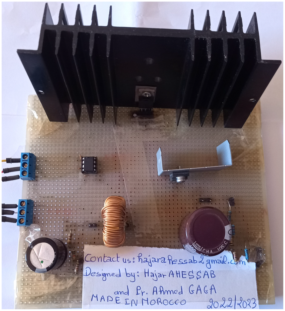
DC-DC Boost converter.
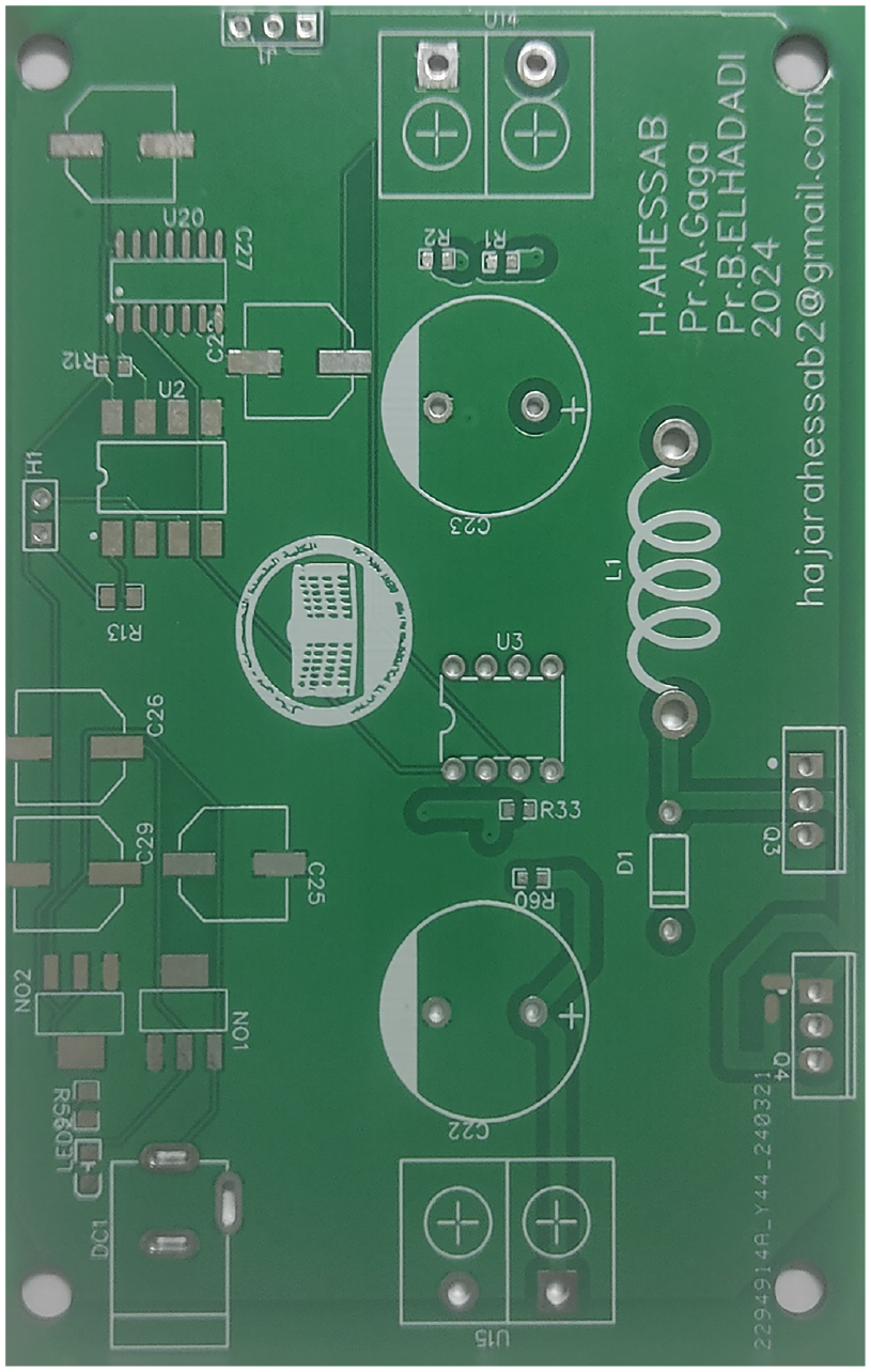
PCB realized for DC to DC boost converter.
Figure 13 present real-world photovoltaic (PV) system designed for microgrids. This system utilizes an intelligent artificial neural network to extract the maximum power from the PV panel through a boost converter. To convert the DC signal to AC, a single-phase inverter controlled by fuzzy logic techniques is employed, taking into account the load current and reference current. To filter out frequencies other than the fundamental frequency of 50 Hz, commonly referred to as harmonic frequencies, we incorporate a transformer into the output of the inverter. In our research, we employed a single-phase load. The setup combined a PV panel both converter and inverter board. The maind roule of this inverter board is to work bidirectional power flow. For our system we have used This card to operate as inverter in order to inject to the load through a transformer.
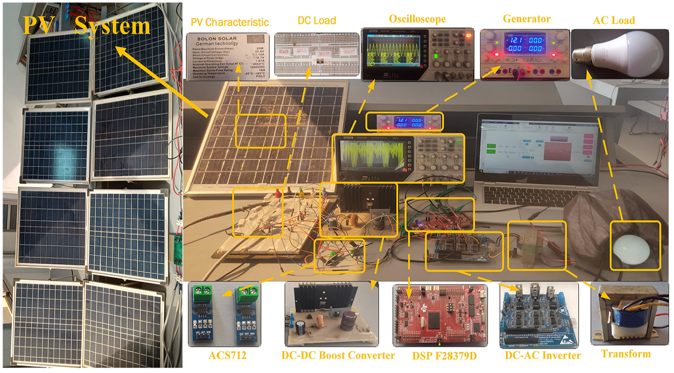
Microgrid-based PV system realized.
Regarding the acquisition, storage, and processing of I and V measurements, Figure 14 illustrates the program’s block diagram that we’ve formulated within the Matlab-Simulink environment. This program facilitates the real-time visualization of attributes such voltage and current.
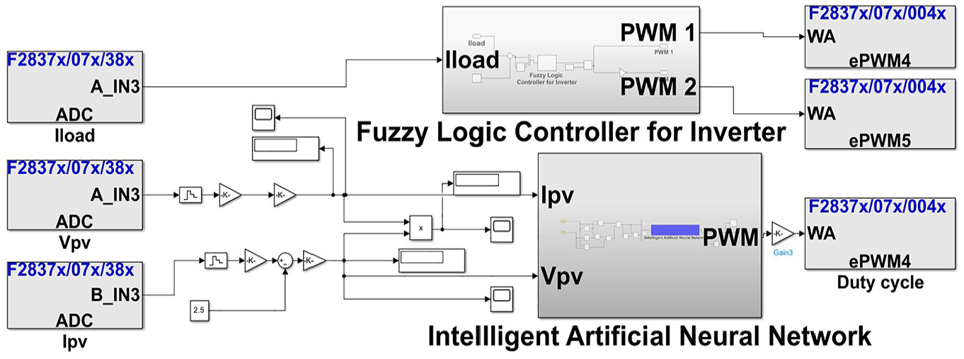
Acquisition data through the DSP F28379D board and process of system unther Matlab-Simulink.
The Figure 15 illustrates the proposed hybrid control system combining an Intelligent Artificial Neural Network (IANN) and a Fuzzy Logic Controller (FLC) for efficient MPPT in photovoltaic systems. The IANN predicts the optimal voltage (Vref) using real-time inputs (current and voltage) through its input, hidden, and output layers, optimizing the duty cycle of the boost converter. The FLC then refines this by using V ref, calculating the error (
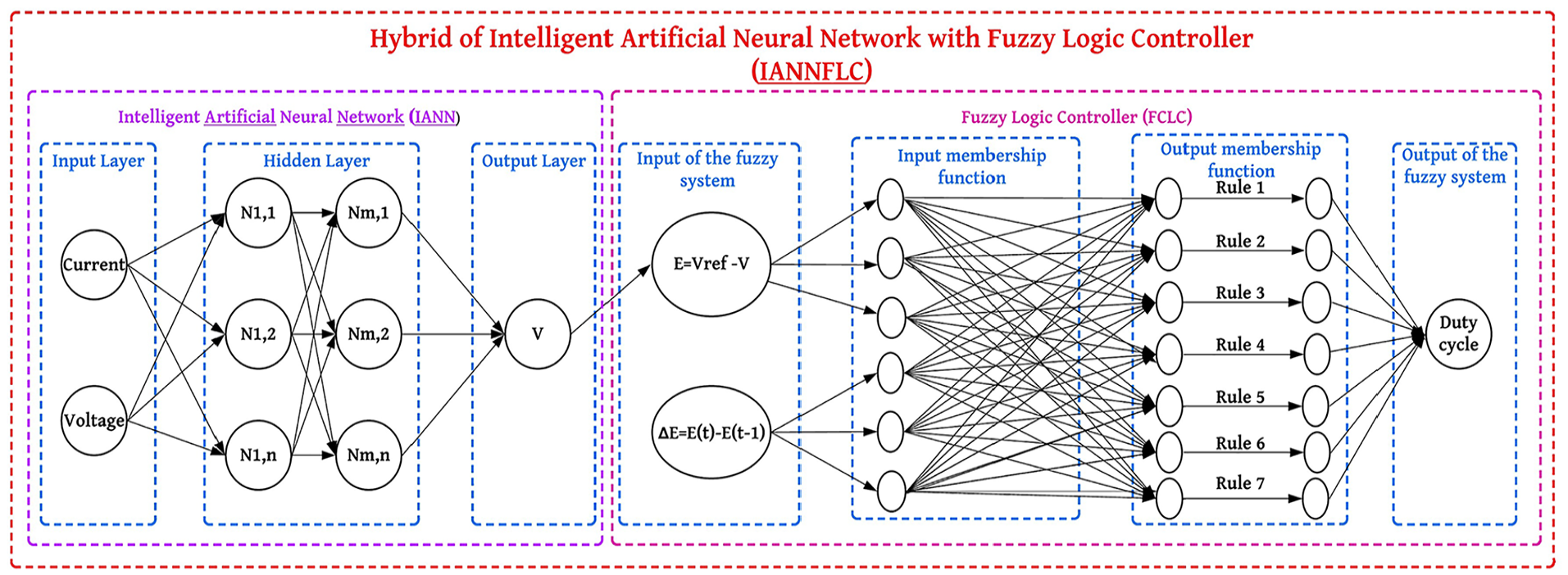
Hybrid control framework of intelligent artificial neural network (IANN) and fuzzy logic controller (FLC) for MPPT in photovoltaic systems.
Results and discussion
Simulation results and discussion
As depicted in Figure 16, the output voltage of the boost converter controller, governed by the hybrid Intelligent Neural Network algorithm, maintains stability at 24.2 V, even in the presence of minor perturbations induced by fluctuations in irradiance and temperature.
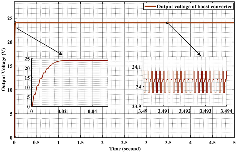
The output voltage of boost Vdc link in MATLAB simulink.
This steadfastness in the output voltage underscores the robust nature of the boost converter system, assuring dependable performance in the face of varying environmental conditions. Figure 17 depict the fluctuations in voltage and current in the single-phase load powered by the PV system. The graphs illustrate that the current and voltage signals are in phase, signifying that variations in current and voltage occur simultaneously, demonstrating synchronized behavior.
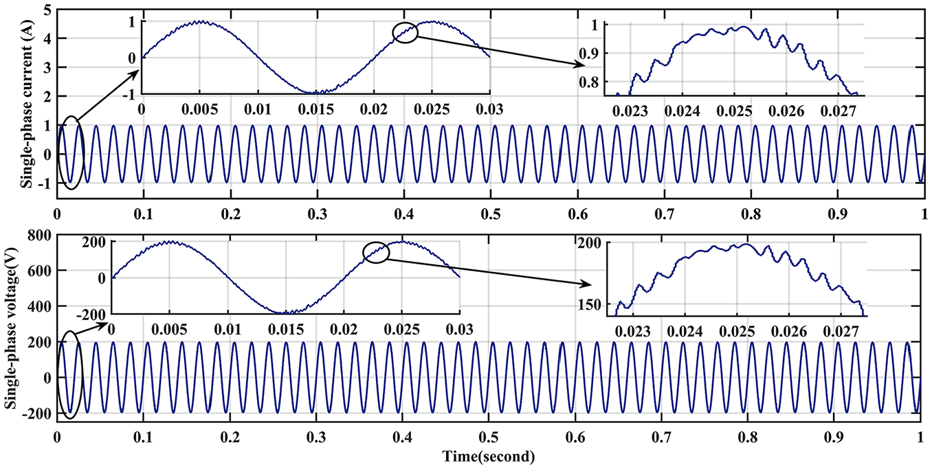
Load current response in MATLAB Simulink.
Practical results and discussion
Figure 18 visually represents the results of the boost converter, where the output voltage reaches up to 311 V. This voltage regulation is based on the duty cycle. To optimize the power extraction from the panels, especially under shading conditions, we employed the Intelligent Artificial Neural Network (IANN) approach. This innovative method allowed us to achieve multiple values of Vdc, adapting effectively to varying conditions.
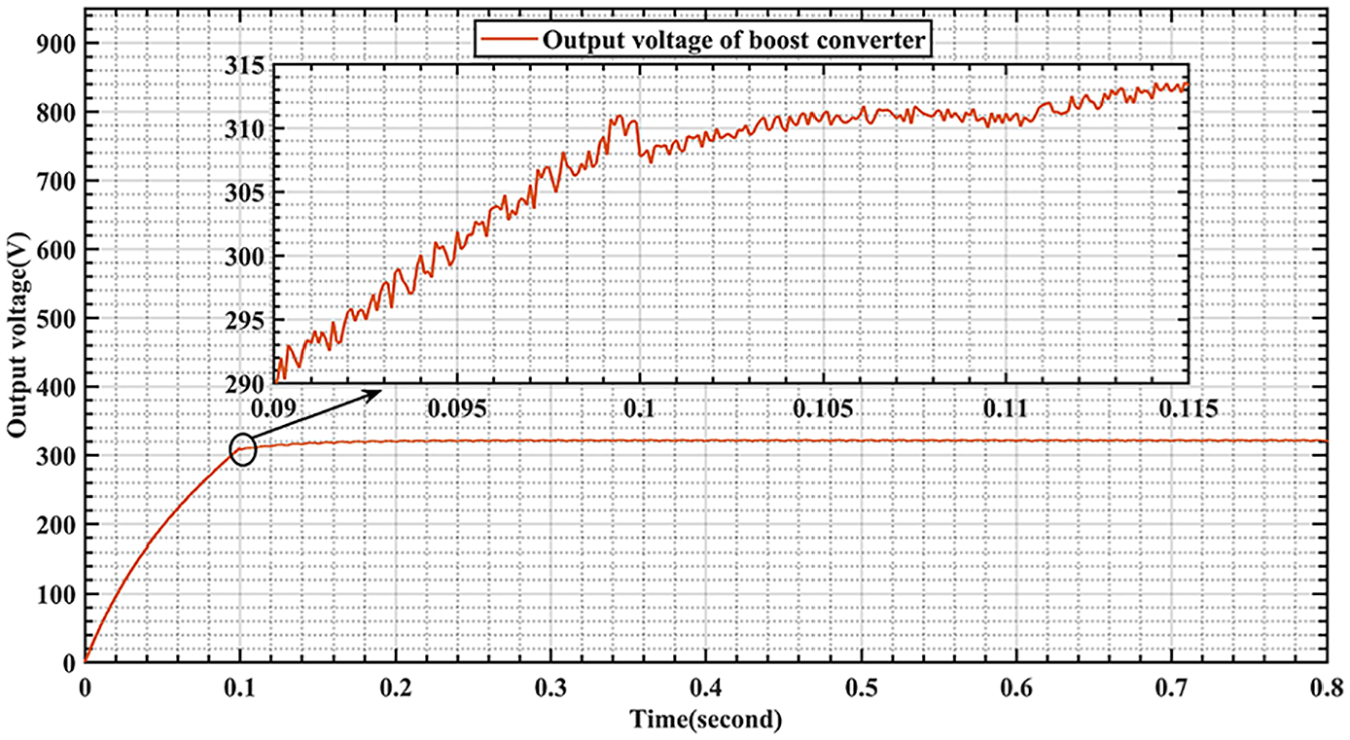
The output voltage of the boost Vdc link.
The figure further demonstrates the Vdc values under perfect environmental conditions, highlighting the robustness of our approach. The use of the ANN algorithm ensured precise regulation of the output voltage. By integrating the IANN, we could extract the maximum power from the panels even in less-than-ideal conditions, showcasing the system’s efficiency and adaptability. The ANN algorithm’s ability to maintain a consistent 311 V output under these conditions underscores its effectiveness in managing and optimizing the boost converter’s performance.
The voltage of the DC link serves as the input for the inverter, which converts the DC voltage into sinusoidal signals. These sinusoidal signals are observed using an oscilloscope, allowing the results to be extracted via a USB connection. Figure 19 shows the load voltage, illustrated as a sinusoidal waveform with an RMS value of 220 V and a peak value of 311 V. We have used a resistive load with a minimum power of approximately 70 W.
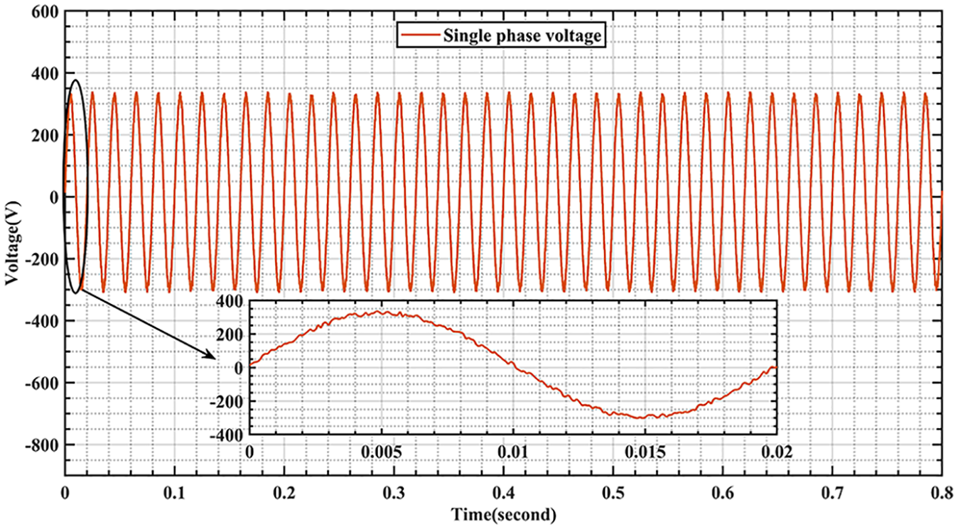
The voltage of load.
Figure 20 provides a detailed illustration of the variation in load current. The root mean square (RMS) value of the current is approximately 0.70 A, while the maximum current reaches 1 A. This variation in current highlights the effectiveness of the fuzzy logic controller in minimizing Total Harmonic Distortion (THD). By employing the fuzzy logic controller, the system achieves a more stable and efficient performance, ensuring that the THD value remains at its minimum. This reduction in THD is crucial for improving the overall quality of power supplied to the load, demonstrating the superior control capabilities of the fuzzy logic approach.
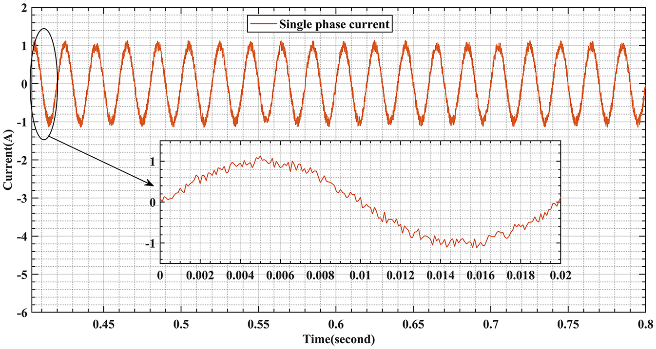
The current of load.
Figure 21 illustrates the relationship between Total Harmonic Distortion (THD) and output voltage. Optimal controller performance is observed at Vc = 220 V and a current of I = 0.70 A. The primary objective of the proposal is to enhance voltage quality by minimizing THD. Upon comparing waveform and THD performance, it was found that the proposed controller achieved a THD of 2.56%, which is approximately 1.65% lower than other algorithms.
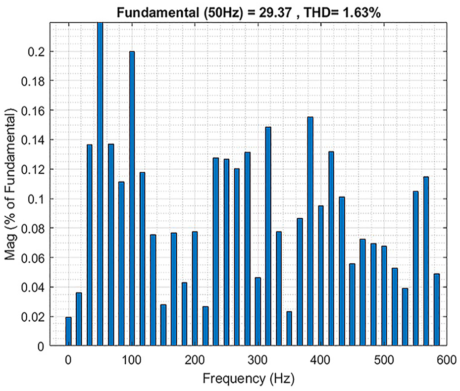
The total harmonic distortion (THD).
The proposed hybrid IANN-FLC control technique offers significant practical benefits for real-world PV systems:
Economic Feasibility: The system is cost-effective, utilizing the DSP F28379D microcontroller and a simplified PCB design, reducing hardware costs while maintaining high computational efficiency.
Adoption Challenges: The deployment requires expertise in artificial intelligence and fuzzy logic, and scalability to larger PV arrays or multi-phase grids may need additional hardware and software adjustments.
Benefits for Grid-Connected Systems: The system ensures precise MPPT, reduces Total Harmonic Distortion (THD), and improves grid stability and energy yield under fluctuating environmental conditions.
Sustainability and Scalability: Its modular design supports future scalability and contributes to sustainable energy solutions by reducing energy losses and enhancing overall efficiency.
Despite adoption challenges, the hybrid system’s adaptability and performance make it a promising approach for advancing grid-connected PV applications.
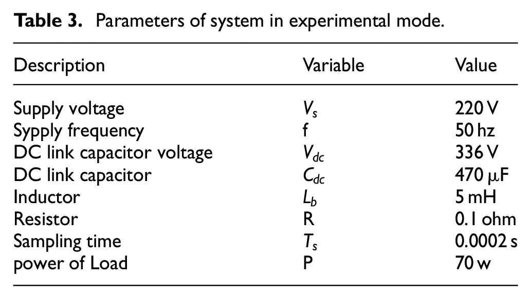
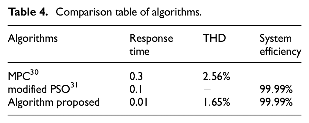
Table 3 presents the system parameters used in experimental mode to obtain real-world results. Meanwhile, Table 4 demonstrates the effectiveness of our proposed algorithm, showing a response time that is 0.7 seconds shorter than other algorithms. Additionally, the THD achieved is very low at 1.65%, compared to 2.56% found in reference Yang et al. 30
Parameters of system in experimental mode.
Comparison table of algorithms.
Conclusion
The proposed model was developed and implemented both in MATLAB-SIMULINK and real-world applications, demonstrating its effectiveness across different environments. The comprehensive analysis of the performance characteristics of the photovoltaic (PV) cell underscores the critical role of the Intelligent Artificial Neural Network (IANN) Maximum Power Point Tracking (MPPT) algorithm in efficiently identifying the maximum power point and optimizing the solar array’s performance. By utilizing a boost converter, the system effectively raises the array voltage to its optimal operational level. Additionally, the fuzzy logic controller significantly reduces Total Harmonic Distortion (THD), ensuring high-quality AC power output.
The implementation on the Launchpad F28379D board highlights the practical feasibility and robustness of the system. This project not only showcases the successful integration of the Artificial Neural Network (ANN) and fuzzy logic controller but also emphasizes their combined impact on enhancing the PV system’s compatibility with the smart grid. Key findings from this work include improved power efficiency and stability, as well as significant reductions in THD, which collectively contribute to a more reliable and efficient photovoltaic system.
In hindsight, this work demonstrates the potential of integrating advanced control strategies to address common challenges in PV system implementation, providing valuable insights for future research and practical applications in smart grid integration.
Footnotes
Acknowledgements
This class file was developed by Ahessab hajar Beni MELLAL, Morocco. I am deeply grateful to my mentors, Prof. Benachir Elhadadi and Prof. Gaga Ahmed, for their guidance. I am sincerely grateful for the time and effort invested by each reviewer in thoroughly assessing this paper.
Declaration of conflicting interests
The author(s) declared no potential conflicts of interest with respect to the research, authorship, and/or publication of this article.
Funding
The author(s) received no financial support for the research, authorship, and/or publication of this article.
Ethical Committee as applicable
Our institution does not require ethics approval for reporting individual cases or case series.
Grant Numbers
This research did not receive any specific grant.
Data availability statement
The data that support the findings of this study are available from the corresponding author, upon reasonable request.