
Abstract
The EMS (Electromagnetic Suspension) maglev train uses active control to achieve stable levitation. The coupled vibration problem of the levitation system itself has always been a key factor limiting the development of EMS maglev train. In order to achieve vibration suppression and rapid response of the levitation control system, a double-loop PID (Proportional-Integral-Derivative) control strategy is first designed. Subsequently, a nonlinear function is used to adjust the system error, enhancing the response speed of the levitation control system. An ESO(extended state observer) is established to reduce the interference of external excitation, and an improved sliding mode switching function of the levitation control system is designed to reduce system chattering. Finally, a fast active disturbance rejection control-sliding mode control (Fast ADRC-SMC) strategy of EMS maglev train is proposed. A comparative analysis is conducted to evaluate the suppression capability and responsiveness of different control strategies under external excitations. Furthermore, the effectiveness of the Fast ADRC-SMC levitation control strategy in suppressing vibrations is validated through comparison with actual measurement data from commercially operated maglev lines. The research results indicate that the proposed Fast ADRC-SMC levitation control strategy exhibits excellent vibration suppression and rapid response capabilities, and the maximum vibration acceleration response of the levitation system is approximately 0.54 m/s2, and the maximum vibration acceleration response of the track beam is about 0.11 m/s2. Compared to the ADRC control strategy, the system response speed is improved by approximately 2 s.
Keywords
Introduction
The EMS (Electromagnetic Suspension) maglev train is a type of contactless transit system, featuring flexible route design, no contact wear, environmental friendliness, and many other advantages, which has also achieved partial commercial operation. 1 However, with the commencement of commercial services, several issues have emerged with the EMS maglev train. These includes: (1) coupled vehicle-track vibration issues significantly; (2) The levitation system exhibits strong nonlinearity and uncertainty, leading to weak adaptability of the levitation controller parameters.2,3
The levitation system of EMS maglev train is a self-excited coupled vibration system, which can induce coupled vibration issues between the levitation system and the track beam when the parameters changed (vehicle parameter, track parameter) easily.4,5 Therefore, many scholars have conducted extensive research on the coupled vibration problems of EMS maglev train, such as dynamics simulation analysis of the whole vehicle and line test research of EMS maglev trains,6–8 and the mechanism of vehicle-track coupled vibration,9–11 and the adaptability of dynamic parameter matching,12–14 and analysis of factors affecting dynamic performance.15,16 These studies all indicate that the levitation system of EMS maglev train is a strongly nonlinear and uncertain system, and the adaptability of system parameters to external excitation is poor, even when the parameters of the track beam, levitation control, and levitation electromagnet do not match, the levitation system is prone to resonance, and the vibration frequency of the levitation system is mostly in the low frequency range(≤10 Hz).This will cause the levitation system failure, even track-hitting phenomena, which can lead to irreversible safety issues and economic losses. Similarly, with continuous research, scholars have proposed many solutions to suppress the coupled vibration of EMS maglev trains: (1) From the structure of the track beam, suppressing coupled vibration by optimizing parameters such as track beam mass and stiffness17,18; (2) From the perspective of the EMS maglev train’s levitation frame structure, our team proposed a mid-mounted levitation frame structure to achieve low dynamic interaction between the maglev train and the track beam19,20; (3) From the perspective of the levitation control system, research on control parameter tuning and adaptive control algorithms has been carried out regarding parameter perturbations, flexible bridges, and external source disturbances.21–23 Compared to levitation control, achieving vibration suppression from the structure of vehicle and track is simple and convenient, but increases the construction cost of EMS maglev train, and reduces the economic advantage of EMS maglev transportation.
Due to the strong nonlinearity and uncertainty of the EMS maglev system, most of the current levitation control strategies are not very ideal. Moreover, due to the lack of verification with actual measurement data, the levitation control strategies designed through theory and simulation always show differences comparing with the real vehicle analysis significantly. Therefore, it is necessary to conduct in-depth research on levitation control strategies. In early studies, some scholars proposed a state feedback control strategy based on the PID(Proportional-Integral-Derivative) control theory and introduced a state observer based on gap signals and acceleration signals, considering the characteristics of high noise in gap differential signals and difficulty in observation.24,25 However, with technological development, PID control can no longer meet the high requirements for control precision. At the same time, PID control theory lacks the ability to perceive external parameters and suppress disturbances. Therefore, combining with artificial intelligence algorithms, some scholars have further proposed adaptive control strategies that enable control parameters to adapt to external disturbances and parameter influences. The widely used control strategies include model adaptive control,26,27 adaptive sliding mode control,28,29 adaptive neural network control,30,31 etc. Among them, the SMC (Sliding Mode Control) method is a robust variable structure control method that is invariant to system perturbations and external disturbances and does not require an exact mathematical model of the controlled object. Li et al. 32 proposed a global fast terminal integral sliding mode control of levitation system, to improve the response speed of the sliding mode controller. Similarly, in terms of anti-disturbance control strategies, Han proposed the ADRC (Active Disturbance Rejection Control) theory for disturbance suppression, combined with a differential tracker and an extended state observer. 33 Stankovic et al. 34 further studied the relationship between PID control strategy and ADRC control strategy based on single degree of freedom and double degree of freedom systems. Zhang et al. 35 applied the ADRC control strategy in the maglev car to achieve more precise trajectory control, proving that the ADRC control strategy has good anti-disturbance ability. It is evident from the studies mentioned that both SMC and ADRC strategies contribute to the enhancement of a system’s disturbance rejection capabilities, albeit with their own inherent shortcomings. The SMC strategy bolsters system robustness by optimizing the discontinuous elements through the switching function. However, upon reaching the sliding surface, the system’s state may oscillate across the surface, resulting in chattering. Conversely, the ADRC strategy employs an ESO (Extended State Observer) to estimate and counteract disturbances, thus diminishing the influence of external excitations on system stability. Nevertheless, the ADRC control strategy is characterized by a relatively slower response speed. In the case of SMC, a prevalent method to mitigate system chattering is the design of an effective reaching law, whereas the ADRC strategy focuses on improving response speed through the design of a differential tracker.
Consequently, this study extends a dual-loop feedback control framework by combine the ADRC and SMC strategies to significantly bolster the system’s resilience to disturbances. Additionally, it employs an extended state observer to estimate the disturbances in SMC, thereby reducing system chatter, and utilizes the switching function of SMC to suppress the coupled vibration between the maglev train and the track beam, improving the levitation system’s anti-disturbance ability. The main contributions of this paper are as follows:
(1) The combination of ADRC and SMC to improve the system’s disturbance rejection and control accuracy;
(2) The utilization of an extended state observer for disturbance estimation in SMC, coupled with an exponential reaching law to reduce system chatter;
(3) The tuning of errors based on a nonlinear function to increase the system’s response speed;
(4) The validation of the controller’s effectiveness using actual measured line data.
Single levitation electromagnet model
The levitation system of EMS maglev train mainly includes the levitation controller, the levitation electromagnet, the levitation frame, the linear motor and so on. Among them, the levitation controller and levitation electromagnet are crucial parts for achieving levitation. The levitation frame serves functions such as mounting and supporting, while the linear motor provides traction. The specific structure is shown in Figure 1.
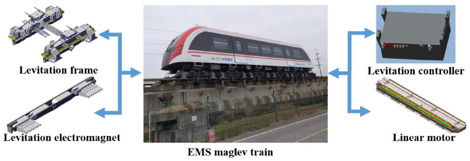
EMS maglev train with all the components.
To achieve stable levitation, the EMS maglev train utilize multiple levitation electromagnets and levitation controllers with the same functions. Therefore, taking a single electromagnet as the research object, a single electromagnet dynamics model is established, as shown in Figure 2.
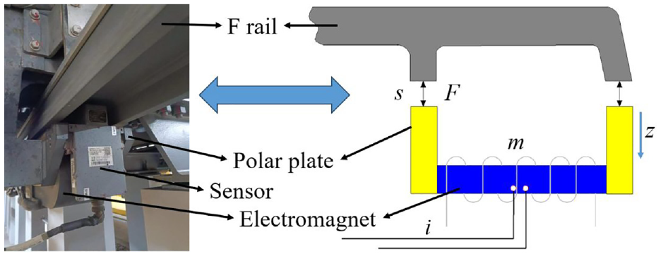
Dynamic model of a single electromagnet.
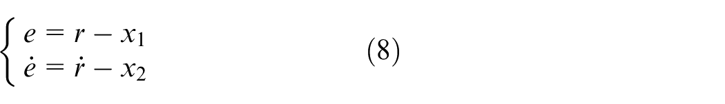
The system dynamics equations can be established as

where m is the mass of levitation electromagnet, F is the levitation force, fd is the external excitation disturbance, z is the vertical displacement of levitation electromagnet.
The circuit equation can be expressed as
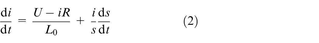
where N is the number of coil turns, i and U are the coil current and control voltage respectively, R is the coil resistance, s is the levitation gap.
L 0 is the inductance coefficient, which is satisfied
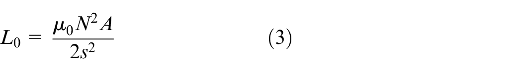
where μ0 is the vacuum permeability, A is the magnetic circuit area.
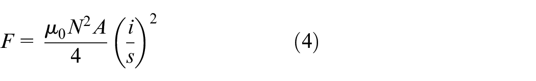
The levitation force of electromagnet can be expressed as
Then the system state variable is set as
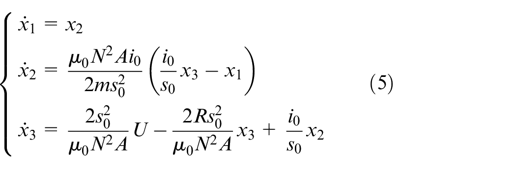
The equation (5) can be taken as a standard matrix form

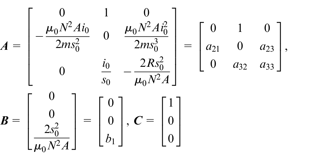
Thus the system state matrices are determined as
Fast ADRC-SMC control
Based on the concept of hierarchical control, the levitation control system is divided into two parts on the basis of state feedback control: position control (position loop) and current control (current loop). The position control employs a sliding mode control method, while the current control uses a PID control method. Meanwhile, an extended state observer for the levitation system is established, as shown in Figure 3.
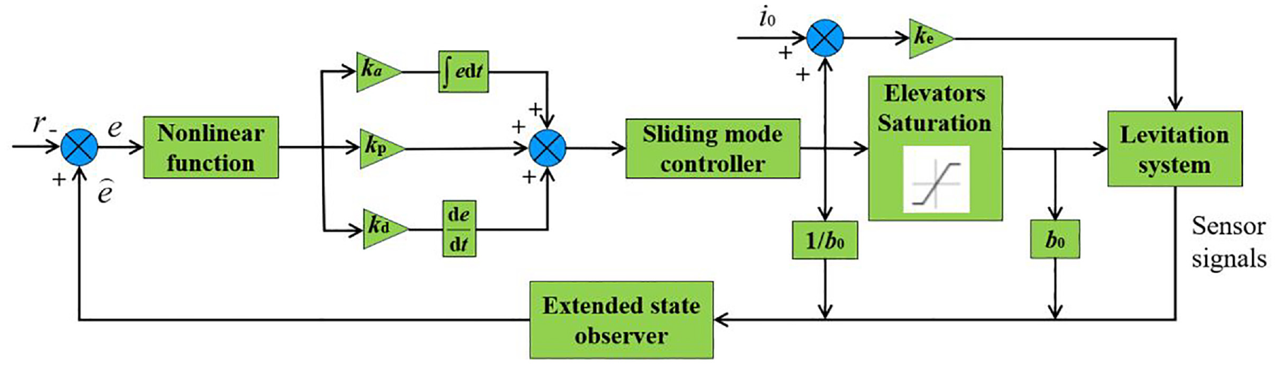
Block diagram of the Fast ADRC-SMC control
Modified switching function based on integral control
The basic principle of sliding mode control: Through controlling its own structural changes, causes the state trajectory of the system starting from any position to approach a specified switching curve and slide along the curve to the origin. This control method is invariant and has good robustness and anti-interference against uncertain factors compared to other control methods. When parameter selection is not suitable, the sliding mode control will cause the system response speed to be too slow and the overshoot to be large. Therefore, in order to improve the system response speed and reduce the overshoot, a nonlinear function is used to adjust the system error. The form of the nonlinear function is

where α and δ is a constant term and all are less than 1, The influence of different parameters on the fal function is shown in Figure 4.
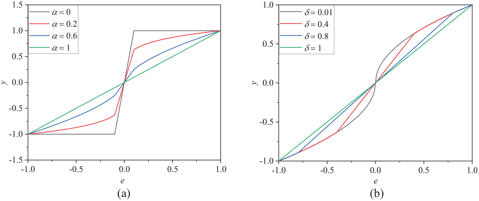
Response of fal function under different parameters. (a) under different α; (b) under different δ.
From Figure 4, it can be seen that when both α and δ are 1, the output of the fal function is a linear line. However, as α decreases, its nonlinear characteristics become apparent, and the amplitude at the inflection point of the function increases. When α is 0, the maximum amplitude at the inflection point is 1; As δ decreases, the input error corresponding to the turning point continuously approaches 0, but the value of δ cannot be 0. When δ is 0, infinity will appear according to equation (8). Therefore, to accelerate the system response, it is recommended that δ be as small as possible, and α be set to 0.5, which is more appropriate.
And the system error equation can be defined as
where r is expected value of levitation gap, Then the error of input is adjusted by equation (7), and the error form is fal(e, α, δ).
The switching functions applied by the form of polynomials which expanded by Taylor series mostly. Although the structure is simple, it is difficult to achieve precise control over strongly nonlinear systems with this method, and there tends to be significant errors under extreme conditions. Therefore, based on the integral control strategy of PID, an improved switching function based on integral control is proposed as
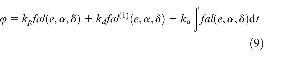
The error gain coefficients kp, kd, ka can be based on the experience of debugging parameters during the line test to determine the basic range of 4500-5500, 80-120, 80-200 respectively. According to the definition of sliding mode control, the switching function meets 36
(1) The sliding mode of system is exist
(2) Reachability condition

To ensure fast response of the system while also reducing system chatter, an exponential reaching law is adopted as

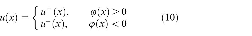
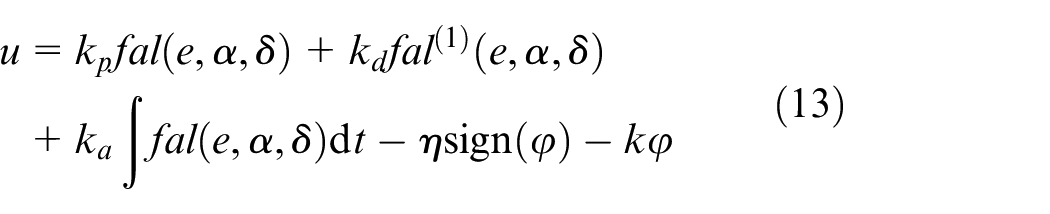
Combining equations (8) to (14), the control law of Fast ADRC-SMC can be derived as
Extended state observer based on expanded dimension space
In the levitation system of EMS maglev trains, it is difficult to directly measure differential signal of gap, thus a state observer is used to reconstruct the differential signal. Based on the concept of active disturbance rejection control, disturbances are treated as state variables of the system, which allows for feedback control targeted at disturbances. This is known as the extended state observer. 37 An extended state observer is designed using feedback signals from gap sensors and acceleration sensors. This makes the state observer dependent only on sensor signals rather than system structural parameters, resulting in stronger robustness.
Then the observer state variable is set as
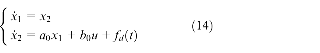
where fd(t) is the external excitation of the system.
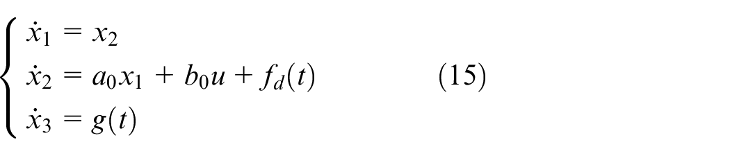
According to the extended space theory, define the extended state x3 = fd(t), Assuming that the derivative of fd(t) exists and is bounded, denote
Taking the extended state observer variable as
The extended state observer can be designed as
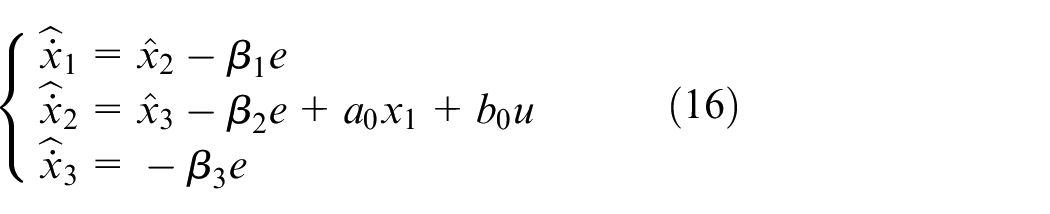
where
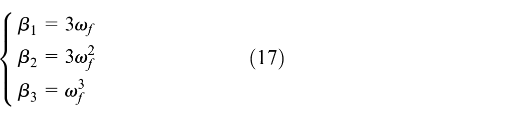
where
Levitation system stability proof:
1) V(x) is positive definite, that is, V(x) > 0 for all x ≠ 0 and V(0) = 0; 2) 3)
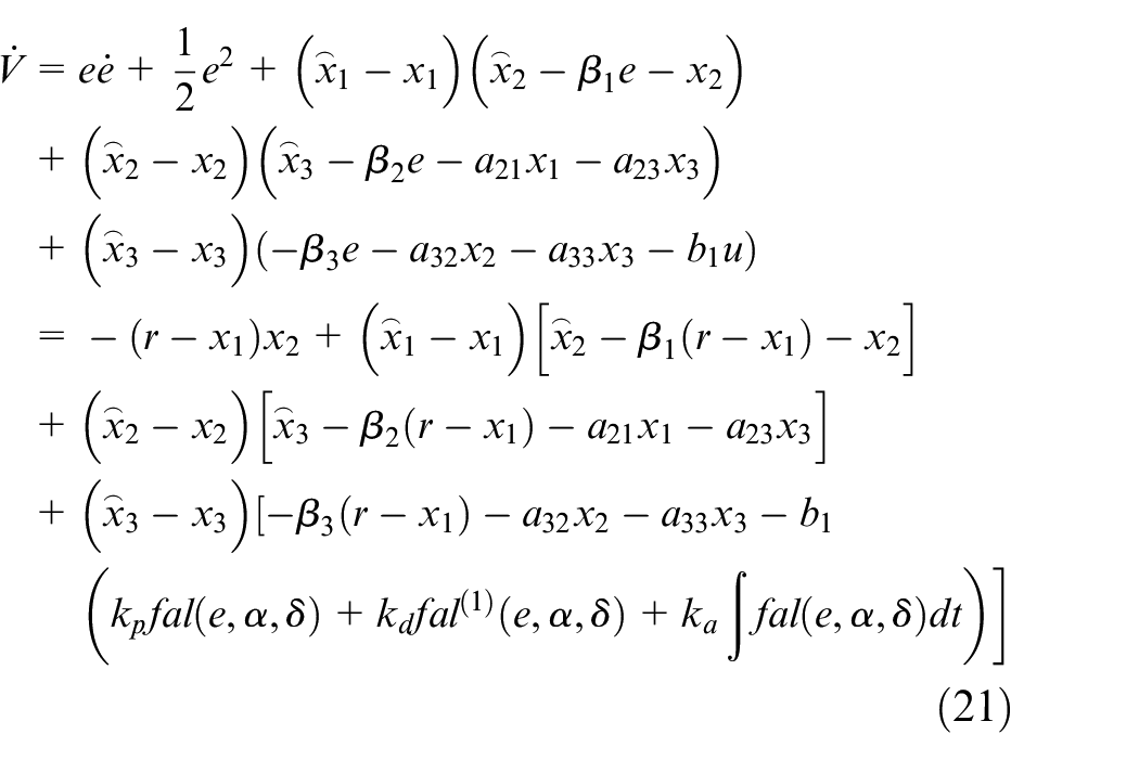
And Construct a Lyapunov function that satisfies
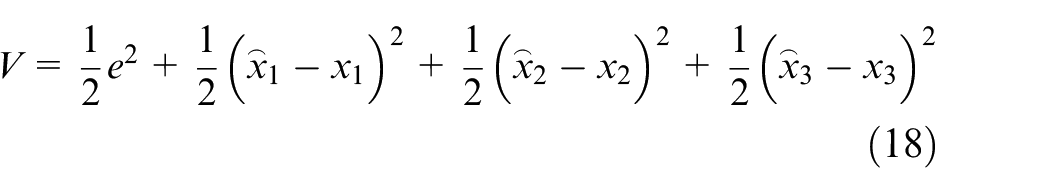
By taking the derivative of V, we can obtain
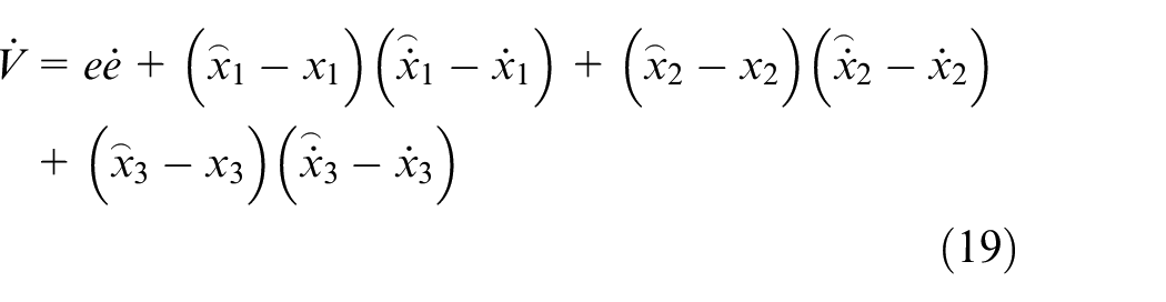
It can be seen that V is clearly positive definite from equation (18), therefore it is necessary to prove that the derivative of V is negative definite, and the system is asymptotically stable.
According to the state observer equation (16), the system state matrices and error equation (9), we can obtain
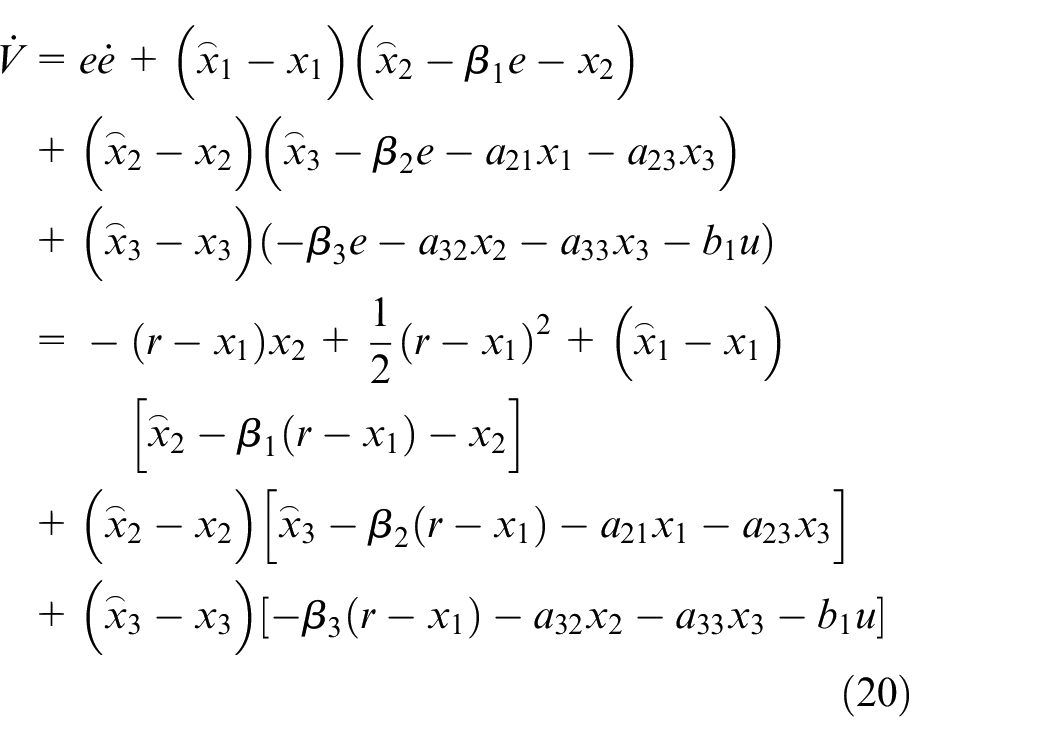
Further based on the expression of the control law equation (13), we can obtain
To satisfy
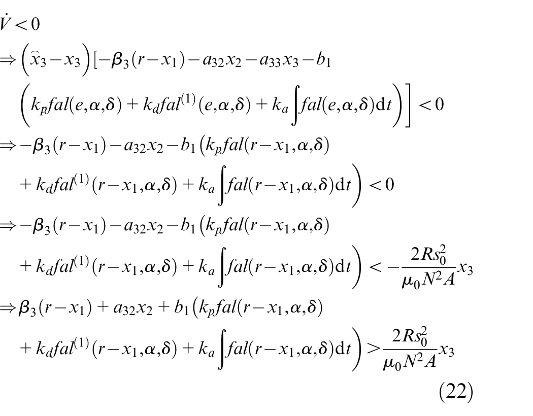
Therefore, it is necessary to adjust the Fast ADRC-SMC strategy so that the parameters satisfy equation (22), at which point the system is convergent and asymptotically stable.
Numerical analysis
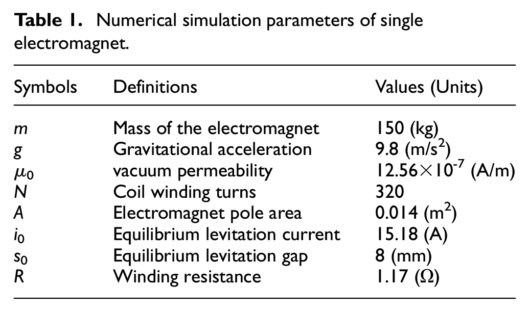
Numerical models of the PID control, Active Disturbance Rejection Control (ADRC), and the proposed Fast ADRC-SMC (Fast active disturbance rejection control-sliding mode control) are constructed in the Matlab/Simulink environment. Simulation analyses under different external excitation conditions are carried out, with the numerical simulation parameters set as shown in Table 1.
Numerical simulation parameters of single electromagnet.
Step excitation
Comparative analysis of the response of a single electromagnet system under step excitation conditions with different control strategies, the results are shown in Figure 5.
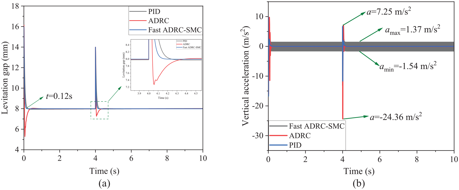
Response of different control strategies under step excitation conditions. (a) Levitation gap response; (b) Vertical vibration acceleration response of electromagnet.
From the results shown in Figure 5(a), it can be observed that under the influence of step excitation, the ADRC has the shortest recovery time but introduces an overshoot. In contrast, the proposed Fast ADRC-SMC can eliminate the overshoot effectively and has a faster response speed and smaller overshoot. The results from Figure 5(b) indicate that in the absence of excitation, the Fast ADRC-SMC introduces a small amplitude of vibration acceleration response compared to the other control strategies, fluctuating from −1.54 to 1.37 m/s2. This fluctuation is caused by the variable structure of SMC, and setting reasonable switching function parameter values can reduce this fluctuation effectively. Under the influence of step excitation, the ADRC introduces a larger vibration acceleration value of about 24.36 m/s2 after the step fluctuation.
Sine excitation
Comparative analysis of the response of a single electromagnet system under sine excitation conditions with different control strategies, the results are shown in Figure 6.
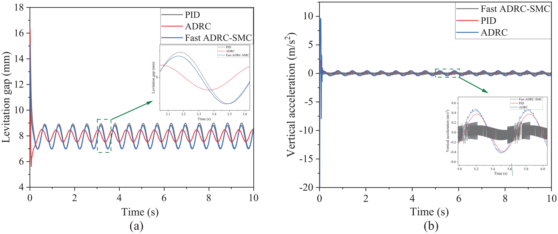
Response of different control strategies under sine excitation conditions. (a) Levitation gap response; (b) Vertical vibration acceleration response of electromagnet.
From the results shown in Figure 6(a), it can be seen that under the influence of sine excitation, the ADRC has better disturbance rejection capability but causes a phase difference in the system, approximately 0.14 s. Compared to the PID control, the Fast ADRC-SMC exhibits certain disturbance rejection capabilities, with both strategies resulting in a levitation gap fluctuation difference of about 0.2 mm. The results from Figure 6(b) indicate that under the influence of sine excitation, the Fast ADRC-SMC has superior vibration suppression effects, with a maximum vibration acceleration amplitude of about 0.22 m/s2. The maximum vibration acceleration amplitudes for the ADRC and PID control are about 0.39 and 0.48 m/s2, respectively. But the Fast ADRC-SMC introduces noise, causing the vibration acceleration response to fluctuat within a small range of 0.12 to −0.22 m/s2.
Track irregularity excitation
A time domain inversion of the calculated track irregularity is performed, and the results are shown in Figure 7.
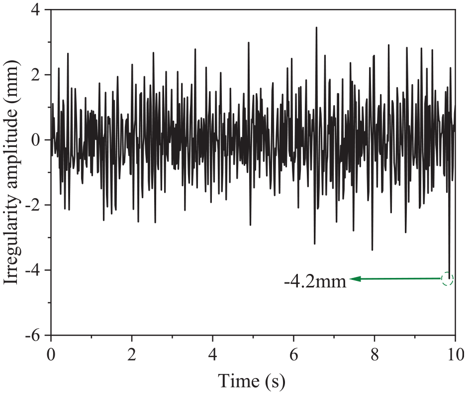
Time domain response of track irregularity excitation.
Comparative analysis of the response of a single electromagnet system under track irregularity excitation conditions with different control strategies, the results are shown in Figure 8.
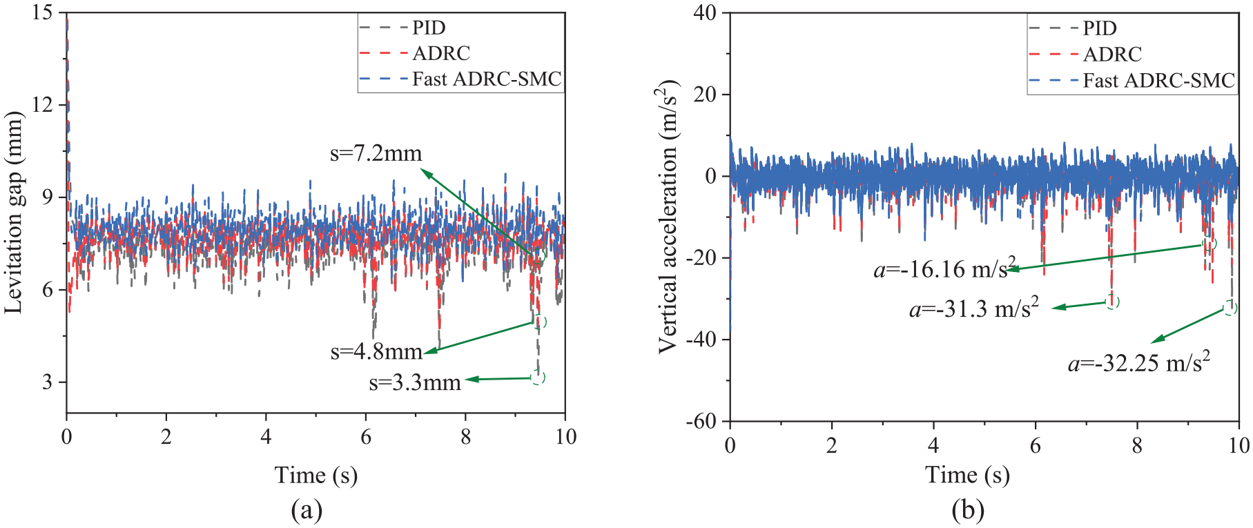
Response curves of different control strategies under track spectrum excitation conditions. (a) Levitation gap response curve; (b) Vertical vibration acceleration response curve.
The results from Figure 8 indicate that the Fast ADRC-SMC exhibits excellent vibration suppression effects. Under the influence of track irregularity excitation, the maximum gap fluctuation of the levitation gap value output by the Fast ADRC-SMC is 0.8 mm, while the ADRC and PID control cause the maximum gap fluctuation is 3.2 mm and 4.7 mm respectively. Meanwhile, the maximum amplitude of the vertical vibration acceleration response of the Fast ADRC-SMC is16.16 m/s2, compared to31.3and 32.25 m/s2 which are caused by the ADRC and PID control strategies respectively, with the track irregularity excitation input being at its maximum, approximately 4.2 mm.
Dynamics simulation and test
Dynamics model
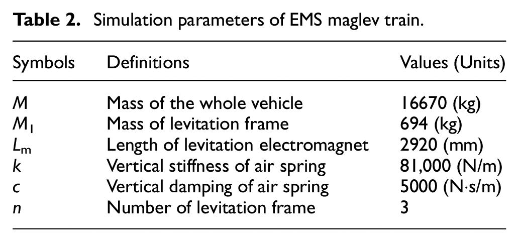
To further verify the accuracy of the designed Fast ADRC-SMC strategy, consider the track beam and car body structure, establish an equivalent levitation model of EMS maglev train, and carry out simulation analysis based on the Fast ADRC-SMC. Set the parameters as shown in Table 2, and establish t levitation unit model as shown in Figure 9.
Simulation parameters of EMS maglev train.
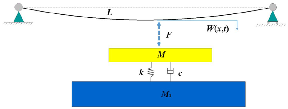
Levitation unit model with track beam and car body.
In vehicle system dynamics, we can find the following differential-algebraic equations [38]
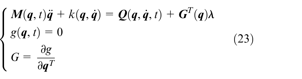
where
And according to the Euler–Bernoulli beam model, the track beam dynamics equation is given by
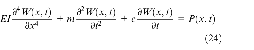
where W(x,t) is the deflection of the beam at position x and time t, P(x,t) is the load of the beam at position x and time t, EI is the bending stiffness of the beam, and
And then the equation (20) can be expressed as
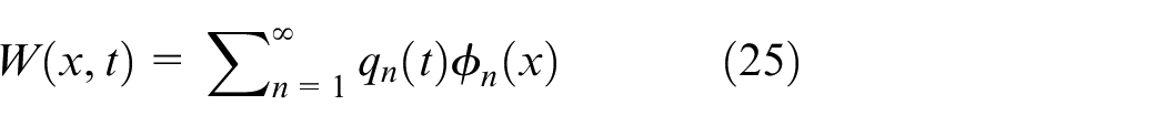
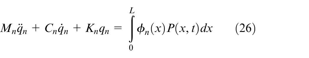
where qn(t) is the modal coordinate of order n (n = 1, 2, 3….) of the track beam, and ϕn(x) is the modal function of order n (n = 1, 2, 3….) of the track beam. And the coefficients of equation (26) can be expressed as

where L is the length of the track beam, ξn is the damping ratio of order n (n = 1, 2, 3….), ωn is the circular frequency of order n (n = 1, 2, 3….).
Dynamics test
The EMS maglev train static levitation test was carried out on the Qingyuan Maglev Line in Guangdong to indirectly verify the effectiveness and anti-interference capability of the Fast ADRC-SMC using test data. The Qingyuan Maglev Line stretches over a total length of 8.01 km, with three stations along its route, and a maximum operational speed of up to 130 km/h. In March 2023, the Qingyuan Maglev Train conducted its initial joint debugging test. The test maglev vehicle is shown in Figure 8, and it has a levitation frame installed at the bottom of the vehicle to support the vehicle and transmit force. Both the levitation electromagnets and linear motors are mounted on this frame. This test primarily focused on conducting static levitation experiments at the Yinzhan Station, with sensors placed at the ends and middle of the levitation electromagnets on the levitation frame, as shown in Figure 10.
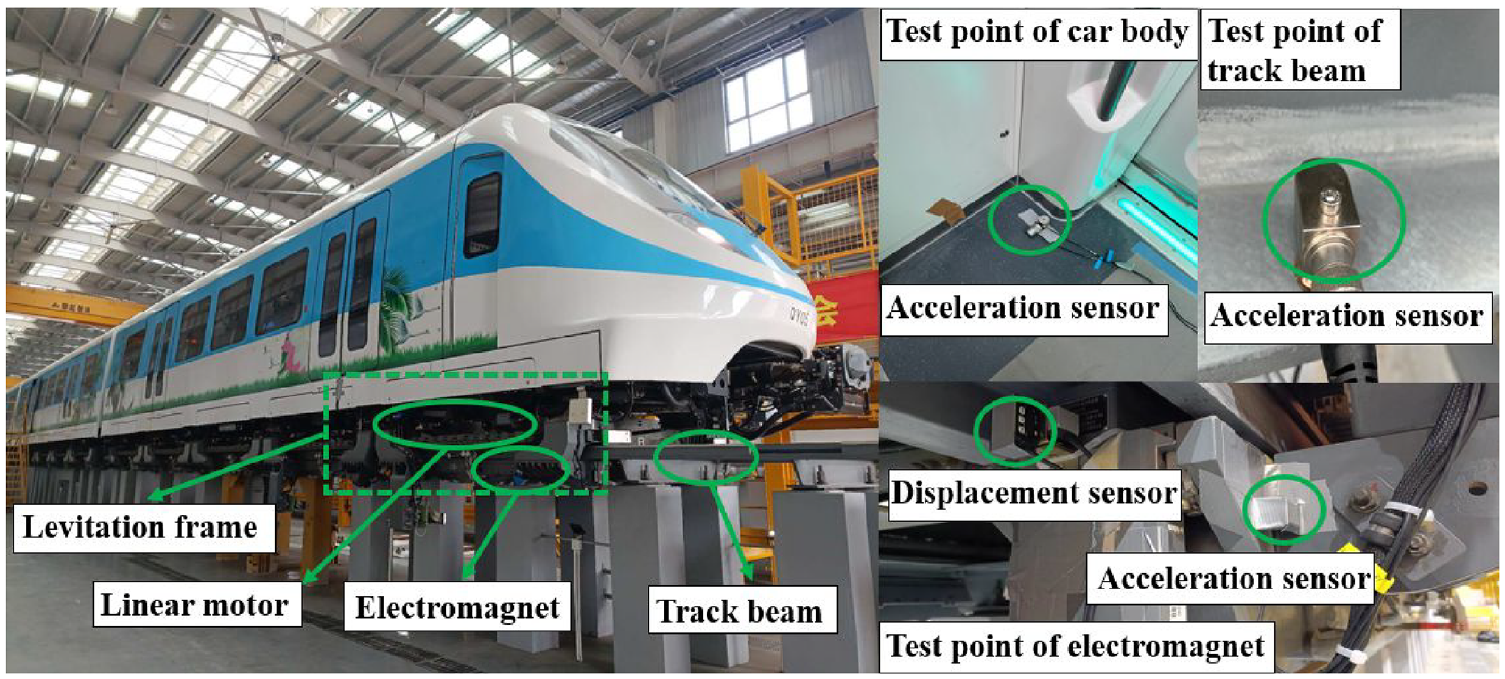
Layout of measurement points of static levitation test
A comparative analysis is also conducted on the effects of PID control, ADRC, and Fast ADRC-SMC on the whole vehicle, as well as the test results of car body vibration acceleration, track beam vibration acceleration, levitation electromagnet vibration acceleration, and levitation gap, as shown in Figure 11.
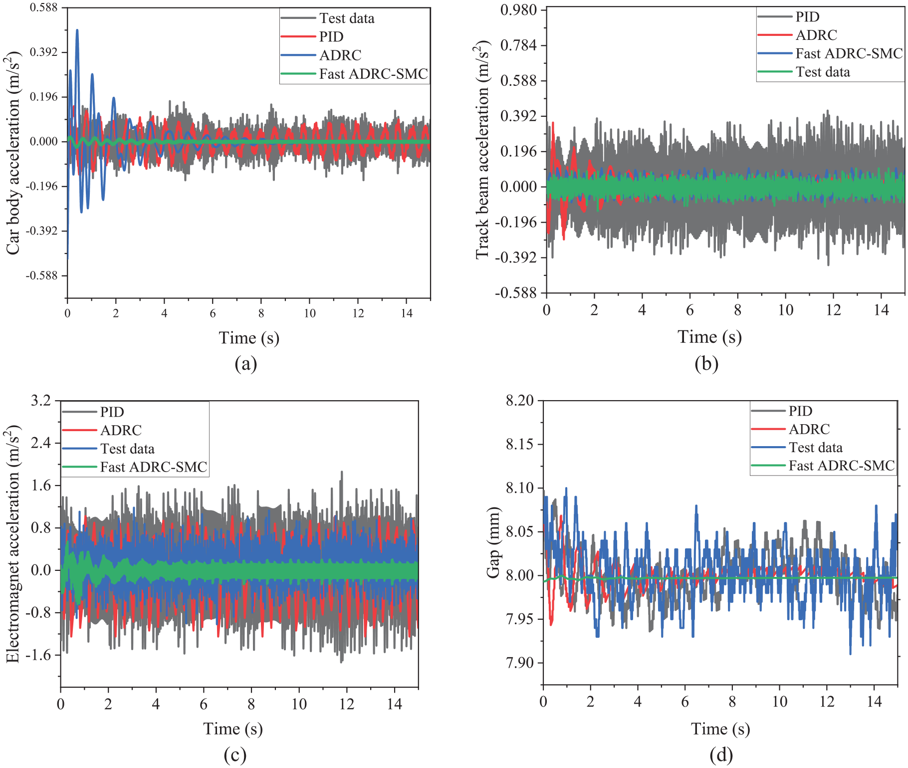
Responses of EMS maglev train with dynamic simulation and test. (a) Car body acceleration; (b) Track beam acceleration; (c) Electromagnet acceleration; (d) gap response.
Figure 11(a) shows the vibration level of the car body, where the maximum vibration acceleration of the test data is about 0.18 m/s2, and the maximum vibration acceleration of PID control strategy is about 0.16 m/s2, and the maximum vibration acceleration of ADRC strategy is about 0.05 m/s2, and the maximum vibration acceleration of Fast ADRC-SMC strategy is about 0.024 m/s2. Figure 11(b) shows the vibration level of the track beam, where the maximum vibration acceleration of the test data is about 0.11 m/s2, and the maximum vibration acceleration of PID control strategy is about 0.19 m/s2, and the maximum vibration acceleration of ADRC strategy is about 0.036 m/s2. The maximum vibration acceleration of Fast ADRC-SMC strategy is about 0.011 m/s2. From Figure 11(a) and(b), it can also be found that the ADRC control system has significant attenuation, but the response speed is slow, and PID control strategy is difficult to suppress coupled vibration. Fast ADRC-SMC strategy has a faster response speed compared to ADRC strategy when further suppressing system vibration, which is about 2 s.
Figure 11(c) shows the vibration level of the levitation electromagnet, where the maximum vibration acceleration of the test data is about 0.12 m/s2. The maximum vibration acceleration of PID control strategy is about 0.19 m/s2, and the maximum vibration acceleration of ADRC strategy is about 0.055 m/s2. The maximum vibration acceleration of Fast ADRC-SMC strategy is about 0.10 m/s2. Figure 11(d) shows the fluctuation level of the levitation gap, where the maximum levitation gap fluctuation of the test data is about 0.1 mm. The maximum levitation gap fluctuation of PID control strategy is also about 0.1 mm, and the maximum levitation gap fluctuation of ADRC strategy is about 0.08 mm. The maximum levitation gap fluctuation of Fast ADRC-SMC strategy is about 0.02 mm. It can also be observed from Figure 11(c) and (d) that Fast ADRC-SMC strategy can further suppress the interference of external excitation effectively.
The root mean square value can describe the amplitude of system vibration and the intensity of impact, better reflecting the whole characteristics of vibration. Therefore, further analysis is conducted based on the root mean square index of system vibration, and the root mean square satisfies:
where x1,x2,…x n is number of data samples.
In terms of the car body vibration level, and the root mean square value of vibration acceleration of the test data is about 0.0053 m/s2. The root mean square value of vibration acceleration of PID control strategy is about 0.0054 m/s2. The root mean square value of vehicle vibration acceleration of ADRC strategy is 0.007 m/s2. The root mean square value of vehicle vibration acceleration of Fast ADRC-SMC control is only about 5.1930 × 10⁻⁴ m/s2.
In terms of the track beam vibration level, and the root mean square value of the vibration acceleration of the test data is about 0.0033 m/s2. The root mean square value of the vibration acceleration of PID control strategy is about 0.0072 m/s2. The root mean square value of the vibration acceleration of ADRC strategy is 0.005 m/s2. The root mean square value of the vehicle vibration acceleration of Fast ADRC-SMC strategy is about 0.0012 m/s2. It can be seen that adopting the Fast ADRC-SMC strategy can reduce the vibration of the car body and track beams effectively.
In terms of the vibration level of the levitation electromagnet, the root mean square value of the vibration acceleration of the test data is about 0.033 m/s2. The root mean square value of the vibration acceleration of PID control strategy is about 0.07 m/s2. The root mean square value of the vibration acceleration of ADRC strategy is 0.012 m/s2. The root mean square value of the vehicle vibration acceleration of Fast ADRC-SMC strategy is about 0.014 m/s2.
In terms of the levitation gap fluctuation level, the root mean square value of the levitation gap fluctuation of the test data is about 0.031mm. And the root mean square value of the levitation gap fluctuation of PID control strategy is about 0.027 mm. The root mean square value of the levitation gap fluctuation of ADRC strategy is 0.014 mm. The root mean square value of the levitation gap fluctuation of Fast ADRC-SMC strategy is about 0.011 mm. It can be seen that under random track excitation, the Fast ADRC-SMC strategy can suppress the fluctuation of levitation gap response effectively.
Conclusion
In summary, the proposed Fast ADRC-SMC strategy uses a nonlinear function to tune the error and set the current loop gain to improve the system’s response speed. At the same time, the possible chattering of SMC control is estimated based on ESO, and the system’s approaching law function is optimized to solve the coupled vibration problem of EMS levitation system and improve the system’s anti-interference ability. The specific conclusion is as follows:
(1) The Fast ADRC-SMC strategy has a faster response time of about 2 s compared to the ADRC strategy;
(2) Compared with ADRC strategy, Fast ADRC-SMC strategy can suppress the coupled vibration of EMS maglev train levitation system effectively. The maximum vibration response amplitudes of the car body and track beam are only 0.024 and 0.011 m/s2 respectively, and the root mean square index are only 5.1930 × 10⁻⁴ m/s2 and 0.0012 m/s2 respectively;
(3) The Fast ADRC-SMC strategy can improve the system’s anti-interference ability effectively. Under the track random excitation, the EMS maglev train levitation system controlled by the Fast ADRC-SMC strategy has a maximum levitation gap fluctuation amplitude which is only 0.02 mm, and its root mean square index is only 0.011 mm.
Footnotes
Acknowledgements
We thank the National Natural Science Foundation of China (Grant Number 51875483) and Science and Technology Plan Project of Sichuan China(Grant Number 2021YJ0002). Similarly, we are very grateful for the help and support provided by the relevant personnel of CRRC Changchun Railway Vehicles Co., Ltd. and Zhihua Ma during the experimental process.
Declaration of conflicting interests
The author(s) declared no potential conflicts of interest with respect to the research, authorship, and/or publication of this article.
Funding
The author(s) disclosed receipt of the following financial support for the research, authorship, and/or publication of this article: This study was funded by the National Natural Science Foundation of China (Grant Number 51875483) and the GF Research and Cultivation Seed Fund Project of Southwest Jiaotong University (Grant Number 2682021GF008).
Ethical Statement
The author(s) declared no ethical approval with respect to the research, authorship, and/or publication of this article.
Informed consent/ Patient consent
Not applicable, as this study did not involve any experiments with human participants or animals.
Trial registration number/date
Not applicable, as this study did not involve any clinical trials.
Data Availability Statement
Data sharing not applicable to this article as no datasets were generated or analyzed during the current study.