
Abstract
Owing to the benefits of uncomplicated design, compact dimensions, and superior power density, interior permanent magnet synchronous motors (IPMSMs) have garnered the attention of numerous researchers, both nationally and internationally. Nevertheless, conventional IPMSM models incorporating sensors, encoders, and additional apparatus often incur substantial equipment expenses and heavily depend on sensor accuracy for effective control. Consequently, the pursuit of sensorless control has emerged as a prominent trend in the domain of IPMSM control. In this work, a new sensorless control based on an integral synergetic observer (ISO) for an IPMSM is presented. The suggested observer has been developed to overcome the challenges posed by conventional observers, such as fragility against various disturbances, and establishing a sensorless control scheme capable of easily integrating into a modern application like electric vehicles. A comparison through numerical simulation tests using MATLAB software, between the proposed observer and the classic Luenberger observer (LO) clearly showed its qualities and its great importance. Notably, the ISO achieves improved performance metrics, such as the integral absolute error (IAE), integral square error (ISE), and integral time absolute error (ITAE). In low-speed control tests, the proposed ISO reduced the IAE by 56.90%, the ITAE by 55.83%, and the ISE by 75.82% compared to the LO.
Keywords
Introduction
The interior permanent magnet synchronous motor (IPMSM) is widely used in various drive applications, including industrial facilities and electric vehicles, where high performance, power factor, and efficiency are essential. IPMSMs offer the advantage of generating high torque with compact rotor sizes due to saliency, which enables both magnetic and reluctance torque production.1,2 To effectively drive an AC motor like the IPMSM, position, and rotor speed information are typically obtained from a linear encoder. However, linear encoders are generally less reliable and more costly than their counterparts in rotating machines, with costs increasing as the track length grows. This poses challenges in applications such as railway traction and long-track motion systems, where the linear encoder is frequently exposed to potentially damaging environmental factors (e.g. sunlight, humidity, mechanical stress). These conditions underscore the importance of implementing robust sensorless methods.3,4
In recent decades, significant research has focused on developing sensorless control techniques for AC drives, which are typically categorized into high-frequency signal injection methods and fundamental model-based approaches.5,6 High-frequency signal injection relies on auxiliary signals to extract motor state information, while model-based methods leverage mathematical models to infer unknown parameters based on available data. This classification has yielded a range of methods shaped by different system models, application constraints, and solution methodologies.7,8
The Extended Kalman Filter (EKF) stands as a foundational technique, merging Kalman filtering principles with nonlinear models to estimate motor states, such as rotor position and speed, with high accuracy even amidst measurement noise. Its capacity to manage uncertainties and system nonlinearities has solidified EKF’s role in sensorless control applications.9,10
Another widely employed approach is the model reference adaptive system (MRAS), which utilizes an adaptive observer to estimate essential motor parameters (e.g. rotor flux and speed) by comparing the actual motor response to a reference model. MRAS is particularly valued for its adaptability to parameter variations and robustness against external disturbances, making it a practical choice in real-world implementations.11,12
Similarly, the sliding mode observer (SMO) is recognized for its robustness, employing sliding surfaces to minimize estimation errors and accurately track motor behavior under challenging conditions. This technique has gained broad application across various motor types, underscoring its reliability and performance in sensorless control.13,14
Although model predictive control (MPC) primarily serves as a control strategy, it often integrates observers for precise state estimation, enabling optimized control actions through predictions of future motor dynamics. MPC’s inclusion of state estimation techniques enhances its utility in sensorless applications by ensuring high control accuracy.15–17
Finally, the extended state observer (ESO) offers advanced capabilities by estimating both system states and disturbances. This observer is particularly advantageous in environments with load variations and parameter uncertainties, contributing to increased robustness and enhanced performance in sensorless control.18,19
Together, these techniques significantly contribute to advancing sensorless control by enhancing adaptability, accuracy, and robustness in motor control applications.
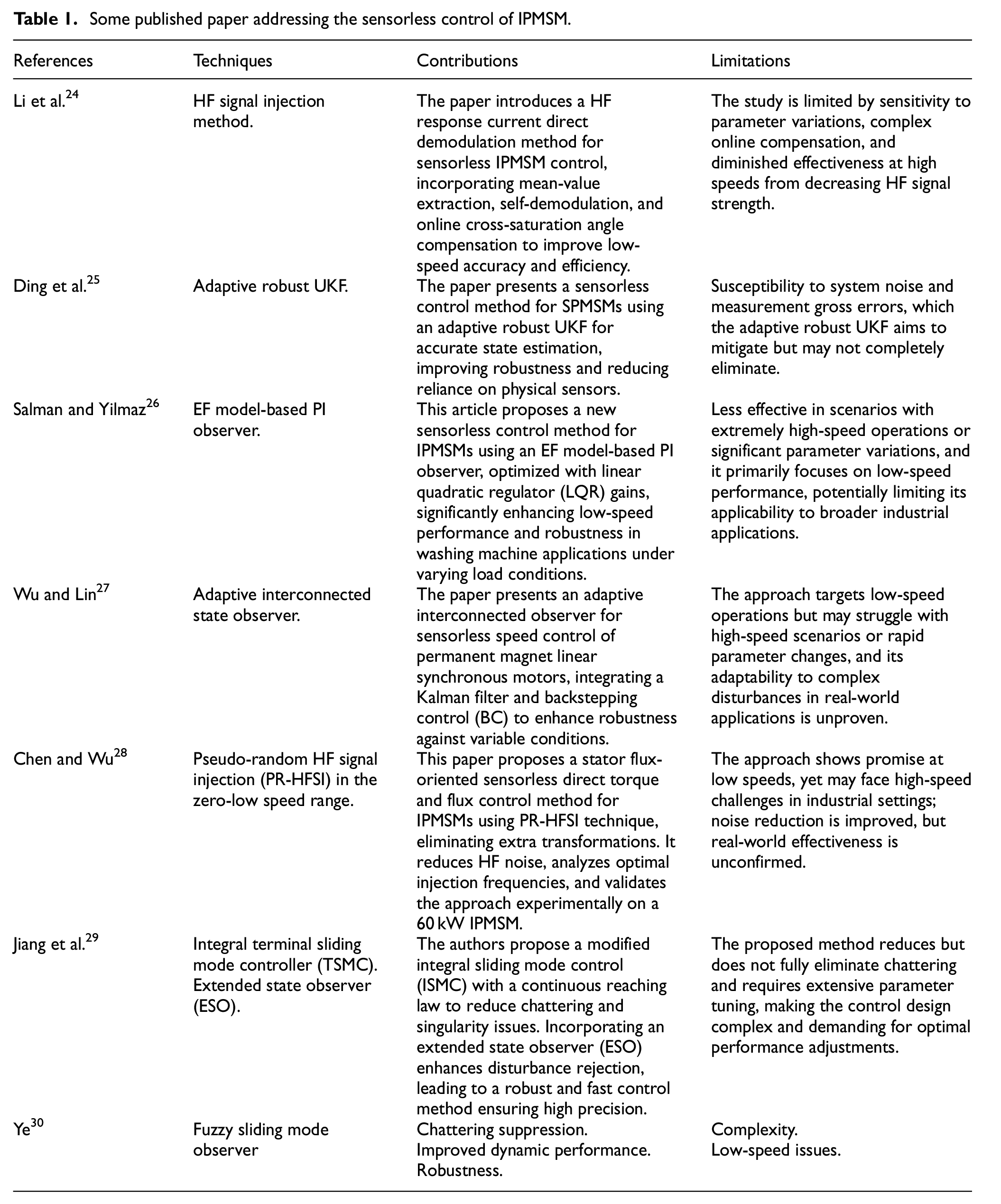
The Luenberger observer (LO), also known as the Luenberger state observer, has emerged as a powerful tool for estimating unmeasured states in dynamic systems. The LO provides an elegant solution by reconstructing the system’s internal states based on available measurements. Its key advantages lie in simplicity, ease of implementation, and computational efficiency. However, there is a notable drawback: the LO’s vulnerability to disturbances and parameter uncertainties, limits its robustness in practical applications.20–23 That’s why, we delve into the theory, benefits, and challenges associated with this widely used observer. Table 1 presents various proposed solutions for improving sensorless control in IPMSM drives found in the literature, including the high-frequency (HF) method, the adaptive robust unscented Kalman filter (UKF), the extended flux (EF) model-based proportional-integral (PI) observer, the fuzzy logic (FL) observer, and other techniques.
Some published paper addressing the sensorless control of IPMSM.
In this paper, we propose to extend the theory of LOs by a new nonlinear approach based on the integral synergetic technique (IST). This suggested technique is a development and extension of the classical synergetic control (SC) which remains one of the robust nonlinear control techniques, as demonstrated in Benbouhenni. 31 Compared to the sliding mode control (SMC) method, the SC approach is simple, uncluttered, and considerably lessens chattering. In Benbouhenni et al. 32 the authors suggest a novel method of SC based on the integral of the macro-variable. Double-loop control is the foundation of this novel design, which increases the effectiveness and robustness of the control. Furthermore, the designed IST law is robust to changes in the system’s parameters.
The main contributions of this study are summarized as follows:
The development of a robust and efficient sensorless control scheme for IPMSM using the integral synergetic observer (ISO).
A comparative study between the LO and ISO applied to IPMSM under normal and exceptional conditions.
Ensuring robustness and accurate reference tracking in the presence of various disturbances.
Enhancing sensorless control performance in low-speed scenarios.
Addressing the limitations of the classical LO technique.
Minimizing the ISE, IAE, overshoot, speed drop, and ITAE compared to LO.
The rest of the paper is organized as follows: Section 2 provides a concise overview of the mathematical structure of the IPMSM. Section 3 elaborates on the definition of the traditional LO approach used for its estimation. Section 4 introduces the designed ISO, which addresses the shortcomings of the conventional observer, with detailed explanations. Subsequently, simulation results are illustrated under various conditions: speed change, low-speed, no load, parameter variation, and load change. These results showcase the reliability and precision of the designed sensorless control approach. Finally, concluding remarks are provided in the last section of the paper.
IPMSM model
As shown in Figure 1, an IPMSM is formed of a stator, rotor, windings, permanent magnets, and a shaft. In IPMSMs, the d-q reference frame is regularly used to facilitate calculations of current and voltage. The magnetic field direction of the rotor acts as the d-axis, which runs along the magnetic pole centerline of the rotor. The q axis, on the vertical bisector between two adjacent magnetic poles, is defined as the direction orthogonal to the rotor magnetic field. To reduce demagnetization in the field weakening (FW) working zone, a V-shaped technique is used. Furthermore, the reluctance torque produced by the difference in d-axis and q-axis inductances is favorable for increasing speed in the FW working zone. 33
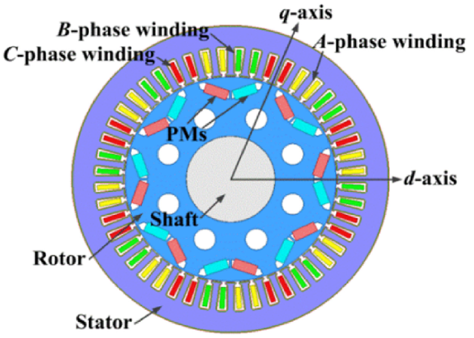
Structure of the IPMSM. 33
The model of the IPMSM is given in equations (1) and (2) 34 :
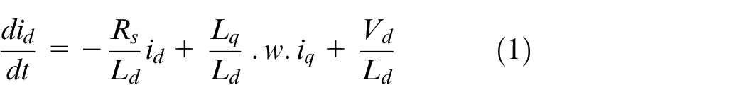
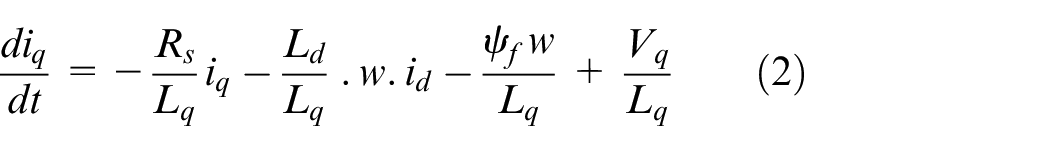
where id and iq represent the stator currents along the d and q axes, respectively; Vd and Vq denote the stator voltages along the d and q axes; Rs signifies the stator resistance; Ld and Lq denotes the direct and quadrature stator inductance; ψf represents the flux linkage; and w represents the rotor angular velocity.
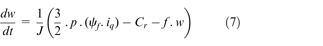
The expression for the mechanical equation of the IPMSM is given by equation (3).
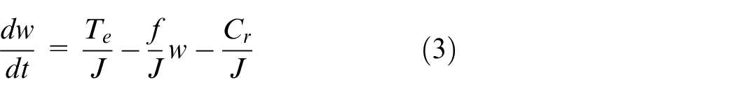
where, Te represents the electromagnetic torque, f denotes the viscous friction coefficient, J is the inertia, and Cr represents the load torque.
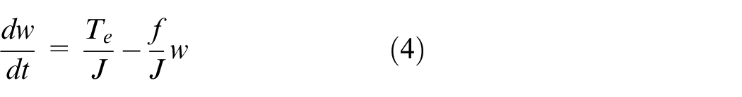
When the machine operates without application of the load torque, equation (3) becomes:
Equation (5) presents the expression for electromagnetic torque.
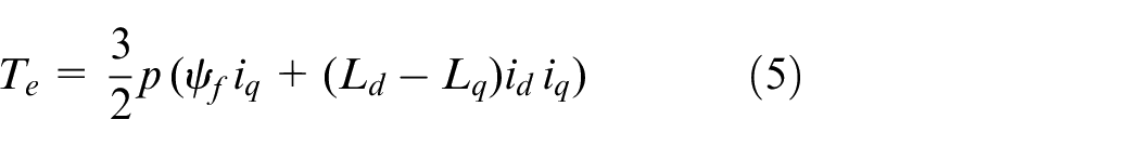
where, p represents the number of pole pairs.
Conventional speed and position estimations for IPMSM
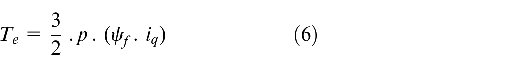
The LO proves beneficial for systems with measurements that aren’t excessively noisy. Additionally, the LO acknowledges the nonlinear state of the IPMSM model. When a system is observable, Figure 2 can be employed to depict the observer. In our model, we omitted the mechanical sensors and employed a second-order LO or reduced-order observer to calculate the load torque and speed, assuming no influence from noise on the system operation (operating in a deterministic environment). We are familiar with the following expression for the torque in an IPMSM35,36:
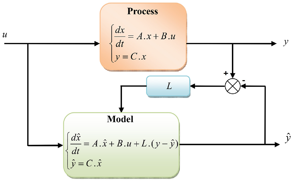
Block diagram of the LO.
By substituting equation (6) into equation (3), we obtain the mechanical speed equation as follows:
This type of observer is designed to estimate both speed and load torque using the stator current quadrature and the machine’s calculated speed equations, under the assumption that the load torque remains constant between sampling intervals. The state variable equation is given as follows:
with
The following system state variables express the LO as the two blocks illustrated in Figure 2.
with:
In equation (9),
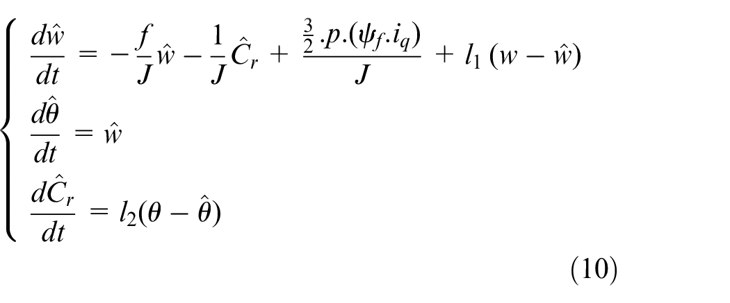
By positioning the poles correctly, the gains that the coefficients l1 and l2 relate to may be obtained by the observer. The reaction is quicker and the system is more noise-sensitive when the pole is closer to 0.
Proposed speed sensorless control for IPMSM
SC theory
In recent years, various nonlinear control systems have been proposed for electrical machinery, with SC techniques (SCTs) standing out as an innovative approach. SCTs offer key advantages such as strong disturbance rejection, ease of design, and guaranteed global stability for the system. SCT shares similarities with SMC, as both methods guide the system dynamics toward predetermined behaviors defined by the designer.
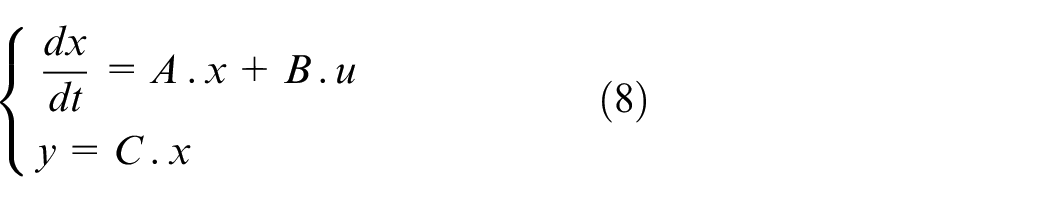
The development of an SCT controller follows a systematic process based on the concept of directed self-organization. The analytical design of aggregated regulators (ADAR) methodology is applied in the SCT design process, which requires the system model to be in a state-space form 37 :
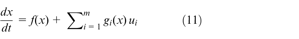
Here, x is a vector of state variables, and ui represents the control inputs for i = 1, 2,…, m. The function f(x) represents the natural (uncontrolled) dynamics of the system, which describe how the state variables evolve over time in the absence of control inputs. The term gi(x) represents the influence of the control inputs ui on the system’s dynamics, dictating how the system responds to control actions. After determining the system’s order and the number of control channels, the state variables are grouped into macro-variables, denoted as Ψ(x), corresponding to each control input. These macro-variables are designed to align with the control objectives.
Each macro-variable

The set of all such manifolds constitutes an invariant manifold, described as:

This invariant manifold represents the desired operational states of the system, aligning with the control goals. To ensure the system converges toward the invariant manifold, it is governed by the following functional equation 38 :
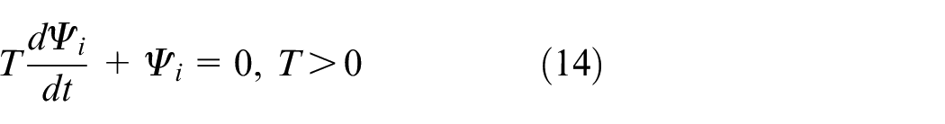
This equation drives the system to approach the invariant manifold exponentially, with the time constant determined by T. The control laws ui are derived by substituting the macro-variables Ψ(x) into equation (14), leading to control laws that depend on the system parameters, state variables, and the convergence time to the invariant manifold. Once the macro-variables are defined, the remainder of the SCT design process is purely algebraic.
Designed ISO strategy
The integral-synergetic technique (IST) is a modified version of the SCT designed to enhance the robustness and characteristics of the classical technique. By adding integration to the classical SCT, the IST technique ensures increased efficiency and strategic effectiveness in enhancing system performance, particularly in enhancing the IPMSM characteristics. The following definition applies to the control legislation of the planned IST:
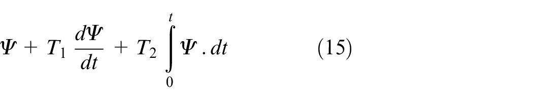
where, the positive parameters for the derivative and integration sections are denoted by T1 and T2, respectively.
Figure 3 showcases the IST. Upon comparing this novel technique with other nonlinear controls such as SMC or BC approach, it becomes evident that it is considerably simpler and more straightforward to implement. Moreover, this method merely necessitates knowledge of the surfaces; it does not mandate familiarity with the mathematical formulation of the system under investigation. As a result, it can be readily applied without the need for extensive computations or knowledge of the system’s mathematical form. The controller proposed in this study stands out from numerous scientific investigations due to its unique concept, principle, simplicity, and ease of use.
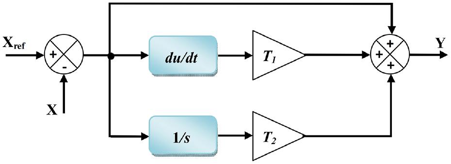
Block diagram of IST strategy.
This paper introduces a novel ISO technique aimed at enhancing robustness and dynamic performance. In comparison to the LO, the ISO demonstrates greater robustness. Through the incorporation of derivative and integral terms of the macro-variable in its design, the designed observer not only exhibits fast dynamic response but also offers significant robustness against parameter uncertainties and disturbances. Furthermore, unlike the traditional synergetic technique, the IST ensures robustness throughout the system’s entire response, starting from the initial time instant.
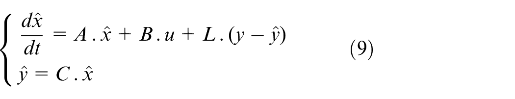
The design of the proposed observer is also based on the nonlinear model represented by equation (10), with the modification of gains l1 and l2 by the new technique IST, illustrated in equation (15), as follows:
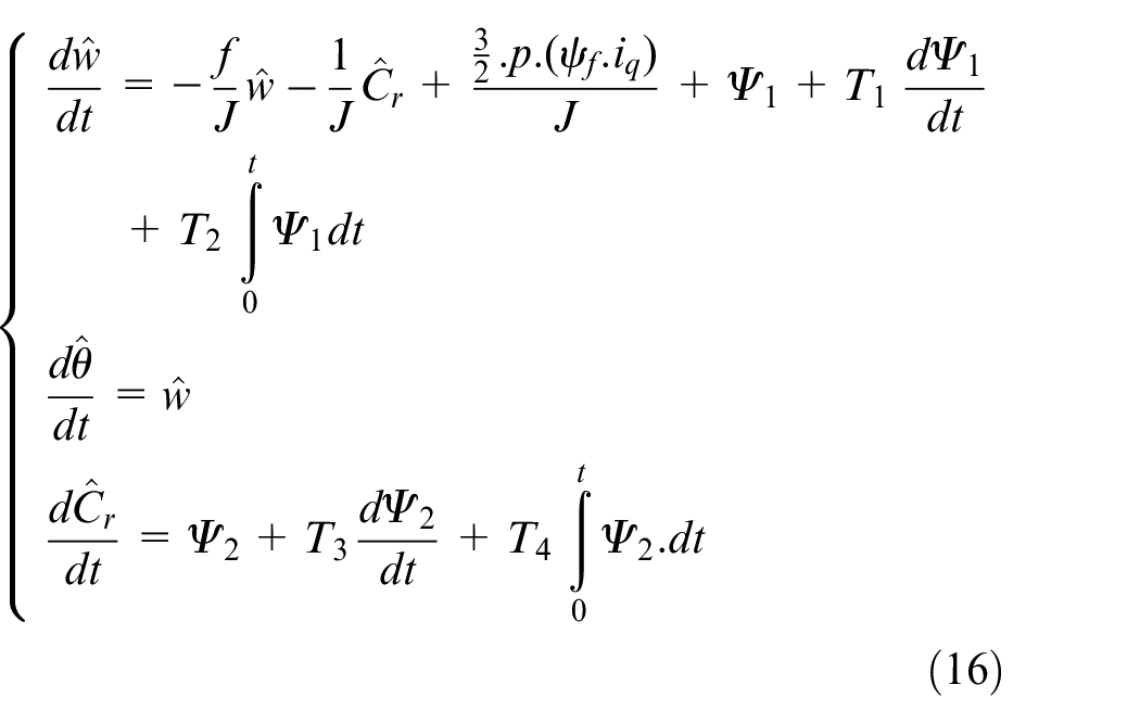
With:


The schematic diagram of the suggested ISO is illustrated in Figure 4.
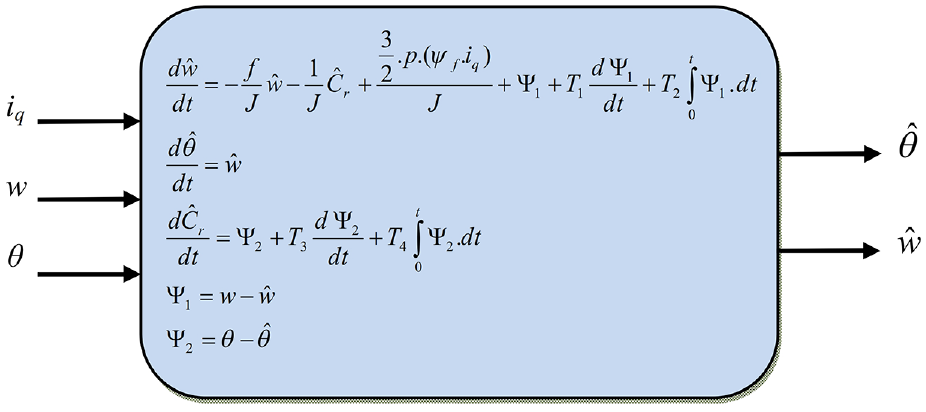
Block diagram of the proposed ISO technique.
Figure 5 illustrates the suggested system block diagram, which incorporates field-oriented control (FOC) for efficient IPMSM management, along with a PWM strategy, and introduces the suggested speed estimation algorithm. The speed controller takes the speed reference wref as input and generates a torque command Tcom to drive the motor at the desired speed. This torque command feeds into the FOC, which produces the reference current idq*. The PI current controller then generates voltage commands vdq*, which are converted into 3-phase signals and supplied to the PWM converter. The actual stator current iq, the real position θ obtained from the position sensor, and w, derived from the real position’s derivative, are used as inputs for the ISO. By applying the position and speed estimation algorithm, the system in Figure 5 achieves sensorless speed control of the IPMSM.
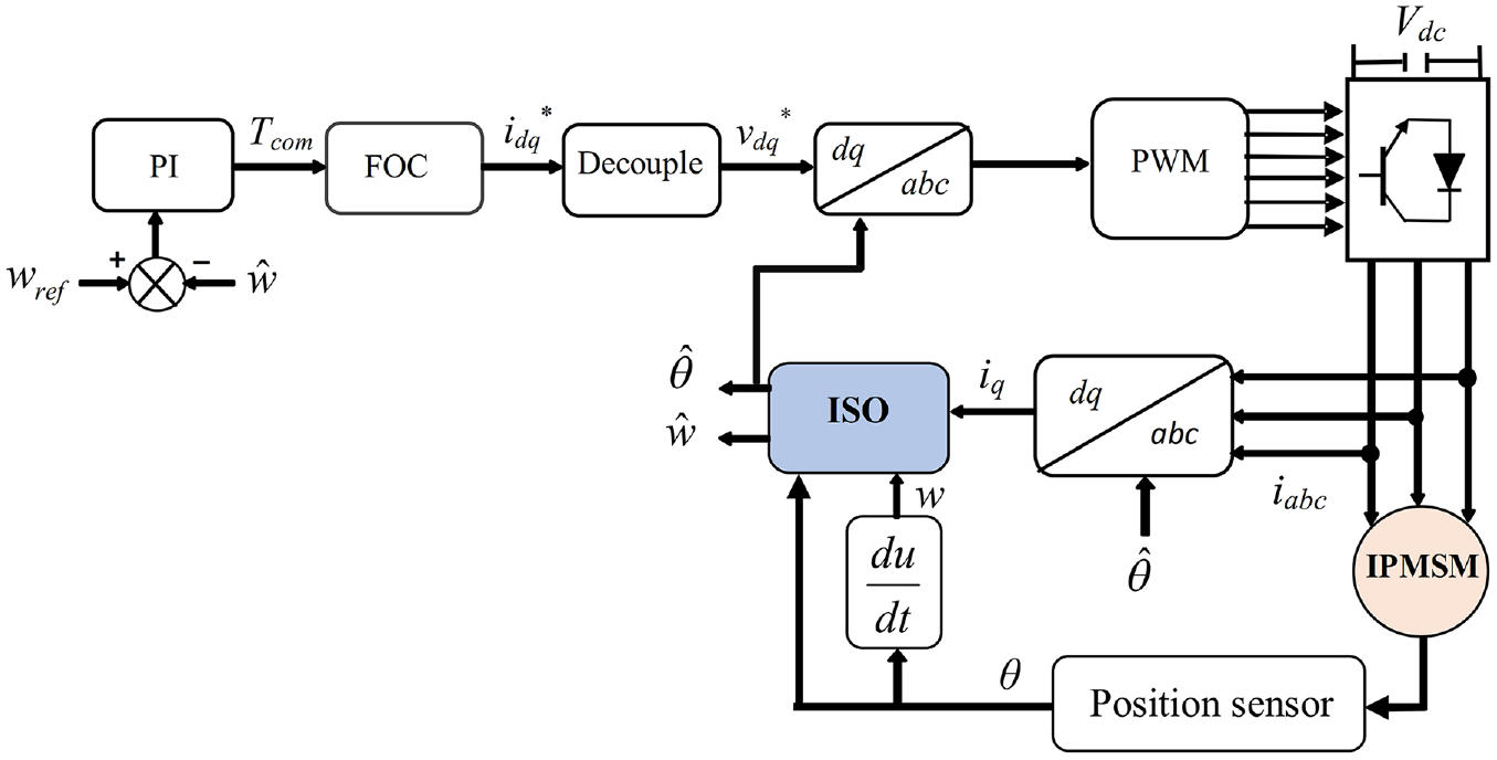
Proposed speed sensorless control system employing the ISO for IPMSM.
Stability analysis
The Lyapunov theorem will be used in this section to demonstrate the asymptotic stability of the closed-loop system when the proposed ISO is applied to sensorless speed control of IPMSM.
We consider V the positive Lyapunov function given in equation (19).
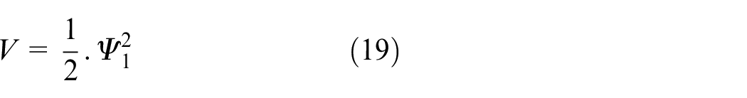
where, Ψ1 is the tracking error defined in equation (17).
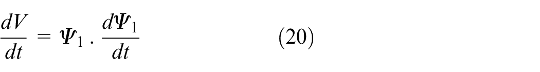
When deriving equation (19), equation (20) is obtained.
With:
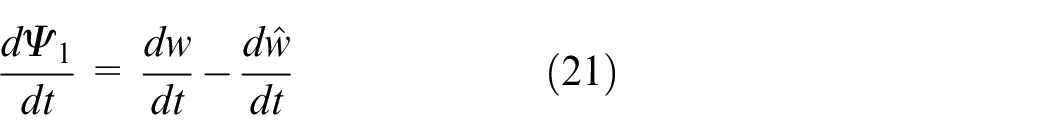
Posing
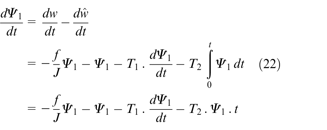
After calculation, equation (22) becomes:
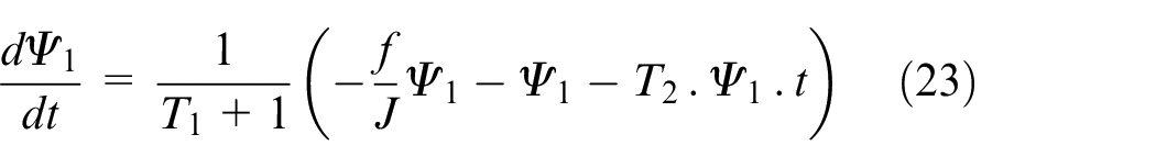
By replacing equation (23) in equation (20), equation (20) can be written.
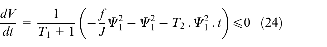
Where, T1 and T2 are positive parameters.
It can be observed that the derivative of the Lyapunov function is negative. Therefore, the asymptotic stability of the closed-loop system is guaranteed according to the Lyapunov theorem.
Simulation results
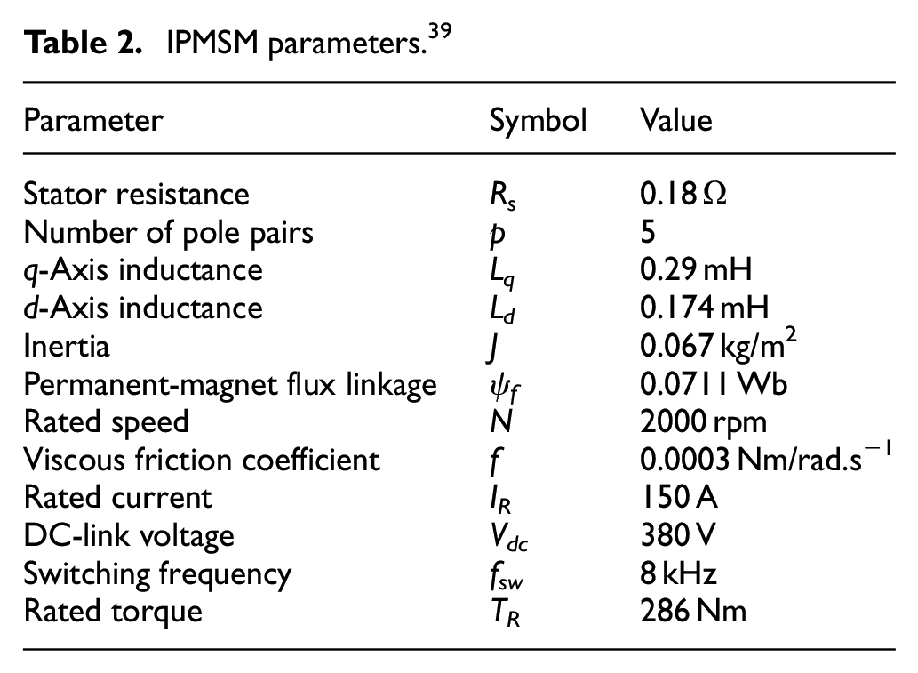
Simulations were conducted under both steady-state and transient conditions to validate the proposed ISO. The performance of the observer was compared with that of the conventional LO, and the IPMSM parameters are listed in Table 2.
IPMSM parameters. 39
Using MATLAB/Simulink software, four simulation tests were conducted to demonstrate the IPMSM capacity to function in all conditions and assess the effectiveness of the observer methodologies examined in this research. The figures in the four condition displays several key parameters, including the real rotor speed, the estimated rotor speed, the reference speed, the stator current components (id and iq), the difference between the real and the estimated speed, as well as the electromagnetic torque.
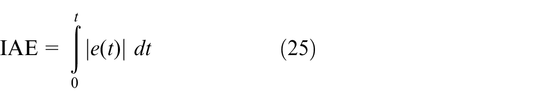
In each test, three numerical values such as: IAE, ITAE, and ISE were calculated and compared for both the proposed observer and the conventional one. These values provide a clear indication of the superiority of the suggested observer in this study.
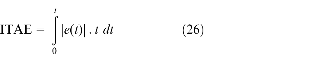
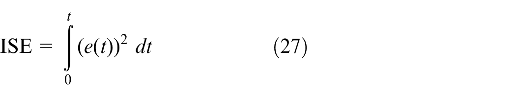
The expressions for IAE, ITAE, and ISE are given as follows:
First test
Figure 6 presents the simulation outcomes when the system is operating in low speed (50 rpm) and without a load, employing both the conventional LO and the proposed ISO, where the speeds for both strategies follow the references well (Figure 6(a) and (b)). Also, the currents in the case of the two strategies take the same form, with zero value and ripples (Figure 6(d) and (e)). Figure 6(c) shows that when utilizing the LO, the maximum value reaches approximately 0.8 rpm for speed error curve under stable conditions. On the other hand, when implementing the ISO technique, it registers a peak value of approximately 0.11 rpm, resulting in a reduction of the speed error by approximately 0.69 rpm. This signifies an enhancement in error reduction of roughly 86.25%. Figure 6(f) demonstrates in the startup a small peak of ISO 5 N.m torque compared to LO torque 9 N.m, the same goes for the stream of current
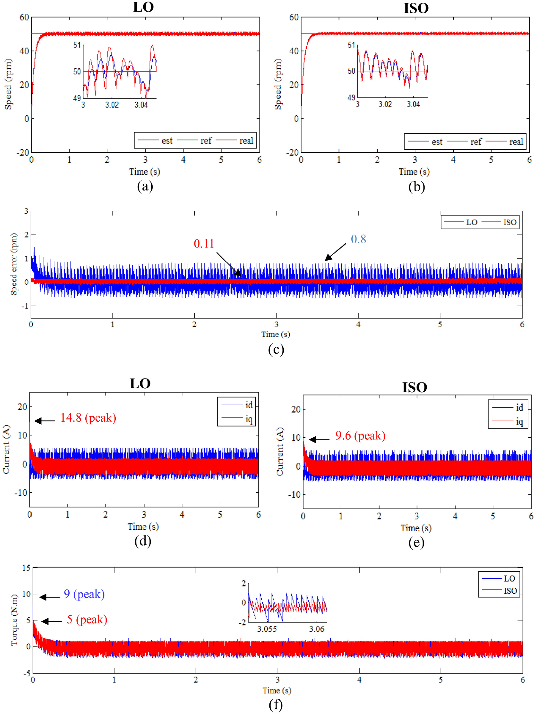
zFirst test results.
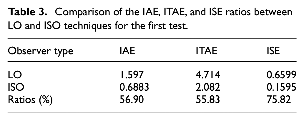
Table 3 presents the IAE, ITAE, and ISE numerical values obtained when the conventional LO and the proposed ISO technique were utilized. The proposed observer achieved an enhancement in reduction estimated at 56.90% for IAE, 55.83% for ITAE, and 75.82% for ISE.
Comparison of the IAE, ITAE, and ISE ratios between LO and ISO techniques for the first test.
Second test
Test tow provides a comprehensive overview of the outcomes observed when the speed command is elevated from 2000 to 3000 rpm, at the 2-s and from 3000 to −2000 rpm the speed control increases the same goes for the current
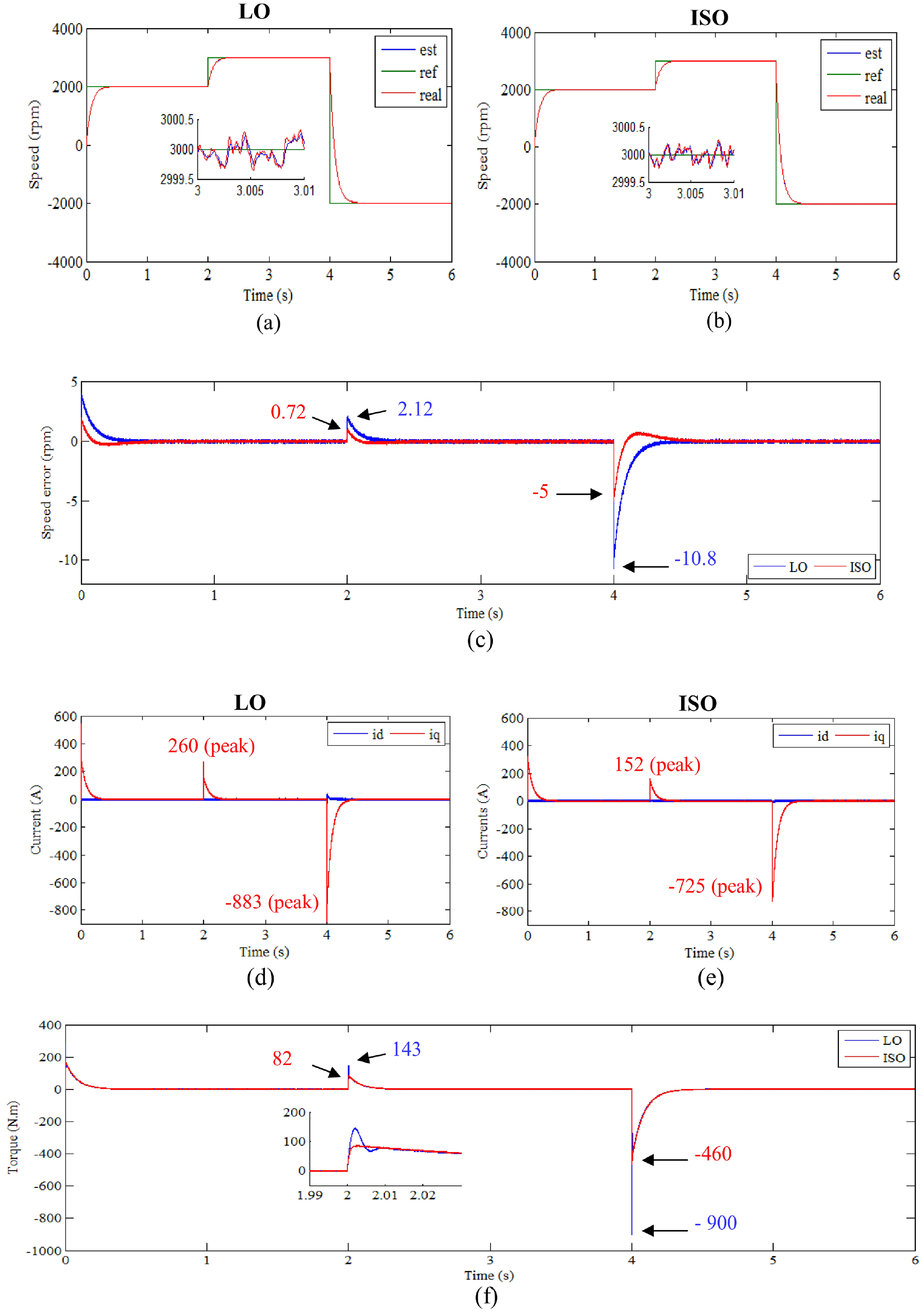
Second test results.
An error between the real and estimated speed is illustrated in Figure 7(c). According to this Figure, and at 2 s, it’s noteworthy that the speed error when using the LO stands at 2.12 rpm while utilizing the ISO a reduced speed error of 0.72 rpm. This indicates an error improvement of around 66.03%. In addition, when the machine’s direction of rotation changes at 4 s, a significant peak is observed in the speed error curve (−10.8 rpm) for the LO, while this peak is substantially reduced for the proposed ISO (−5 rpm), indicating a reduction of 53.7%. The currents and torque are shown in Figure 7(d)–(f), respectively, with the figures demonstrating that the torque and current iq share a similar pattern. Notably, some peaks are observed in these figures, particularly at the moments of speed change, where the peaks are lower for the proposed observer compared to the conventional one.
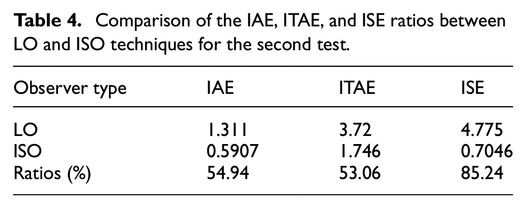
Table 4 displays the numerical values for IAE, ITAE, and ISE obtained using both the conventional LO and the proposed ISO technique. The proposed observer demonstrated significant improvements, achieving reductions of approximately 54.94% for IAE, 53.06% for ITAE, and 85.24% for ISE. These results highlight the superior performance of the ISO in minimizing tracking errors and enhancing overall control accuracy, particularly in reducing cumulative errors and transient peaks. This improved efficiency not only ensures smoother operation but also contributes to greater stability and robustness of the system under varying conditions.
Comparison of the IAE, ITAE, and ISE ratios between LO and ISO techniques for the second test.
Third test
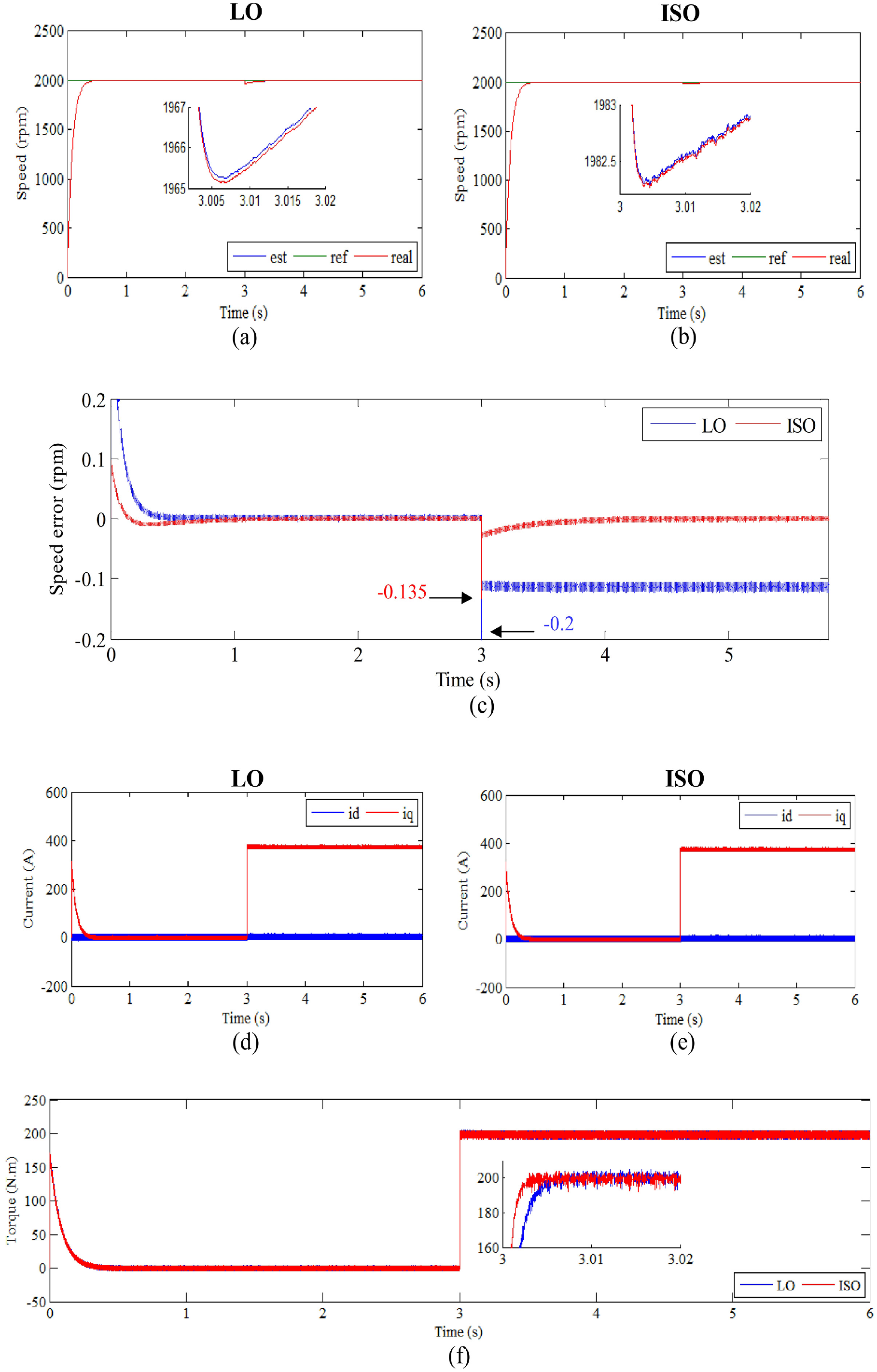
Test three compiles the simulation outcomes under the circumstance where the load torque experienced an increase from 0 to 200 Nm at 3 s. It illustrates the system’s remarkable control performance, attributed to its precise and high-speed regulation. The speeds follow the references well for the two applied observers, as illustrated in Figure 8(a) and (b). Nevertheless, the effect of the application of load is clear for the LO compared to the proposed ISO.
Third test results.
The currents in Figure 8(d) and (e) have the same form of change for the two used observers with the presence of ripples, where at the moment 3 s it is observed that the value of the current iq increases as a result of the increase in the value of the torque at that moment. Figure 8(c) further presents data on speed errors. In the context of the LO, a speed error denoted amounts to −0.2 rpm at the moment when the load was applied. Conversely, within the ISO, the speed error is approximately −0.135 rpm. This translates to an improvement in error reduction of approximately 32.5%. In Figure 8(f), the shape of the torque change in the case of the two strategies is shown. This torque takes the form of a change in the current iq with the presence of ripples, as these ripples are less if the ISO is used compared to the LO technique.
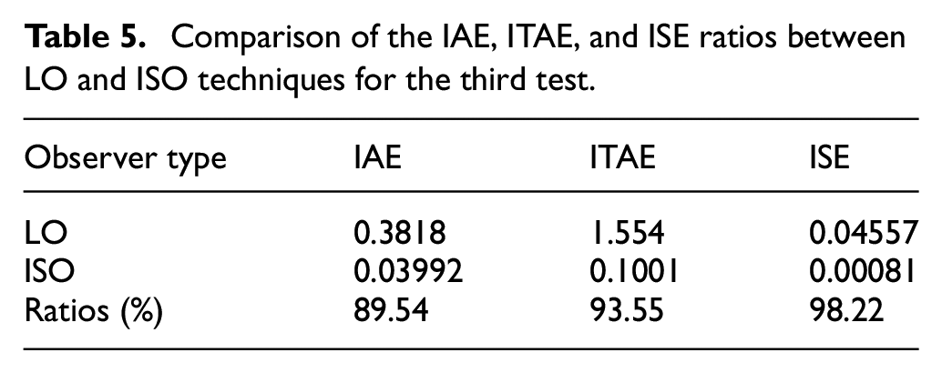
Table 5 presents the numerical values for IAE, ITAE, and ISE obtained using both the conventional LO and the proposed ISO technique. The proposed observer demonstrated substantial improvements, with reductions of approximately 89.54% for IAE, 93.55% for ITAE, and 98.22% for ISE. Based on this third test, it can be concluded that the proposed ISO is more effective at minimizing the impact of external disturbances, such as load application, compared to the conventional LO.
Comparison of the IAE, ITAE, and ISE ratios between LO and ISO techniques for the third test.
Fourth test
The primary necessities were to ascertain whether there had been alterations in the parameters or if the parameter values listed in the IPMSM datasheet were inaccurate. This was accomplished by comparing the outcomes while varying the Rs by 100% and the Ld and Lq by 50%.
These fluctuations visibly impact the stator current, torque, and speed, with the speed error of the LO method exceeding that of the proposed ISO technique (Figure 9). Figure 9(a) and (b) represent speed changes in the two-control cases, where this speed follows the reference well with a fast dynamic response. Specifically, the speed error amounts to roughly 1.4 rpm when using the LO method, whereas with the ISO implementation, it reduces to approximately 0.1 rpm. This indicates an error reduction of approximately 92.85%. Therefore, it can be inferred that the ISO approach exhibits greater robustness compared to the traditional LO technique (see Figure 9(c)). Figure 9(d) and (e) show the currents id and iq for the two controls, as these two currents have the same shape in the case of the two controls with the presence of high ripples when LO is used. These currents ripples are significantly reduced when the proposed ISO is used. The torque curve is represented in Figure 9(f), where the shape of its change is the same as the shape of the change in current iq with the presence of ripples, as these ripples are less if the proposed strategy is used.
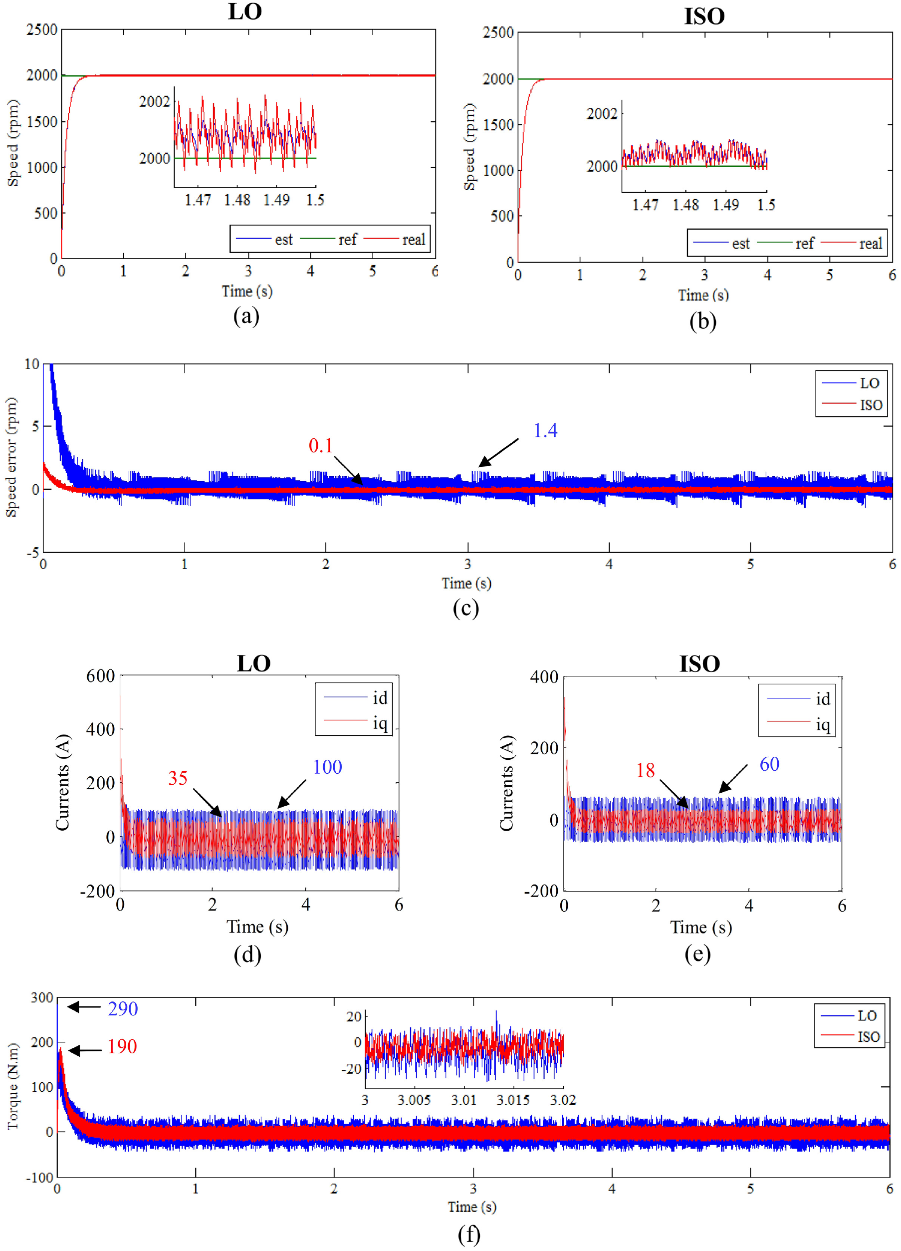
Fourth test results.
The ISO surpasses LO in terms of rapid convergence and disturbance estimation, as evidenced by Figure 9(d)–(f). Across all tests, it is observed that the proposed strategy yields a smaller amplitude for the signals in the initial stages of current and torque compared to the conventional technique.
The numerical values of IAE, ITAE, and ISE obtained using both the LO and the ISO techniques are presented in Table 6. The ISO proves significant improvements, with reductions of approximately 84.10% in IAE, 32% in ITAE, and 97.33% in ISE. From this fourth test, it can be inferred that the proposed ISO is more efficient in minimizing the effects of internal disturbances, such as variations in machine parameters, compared to the LO.
Comparison of the IAE, ITAE, and ISE ratios between LO and ISO techniques for the fourth test.
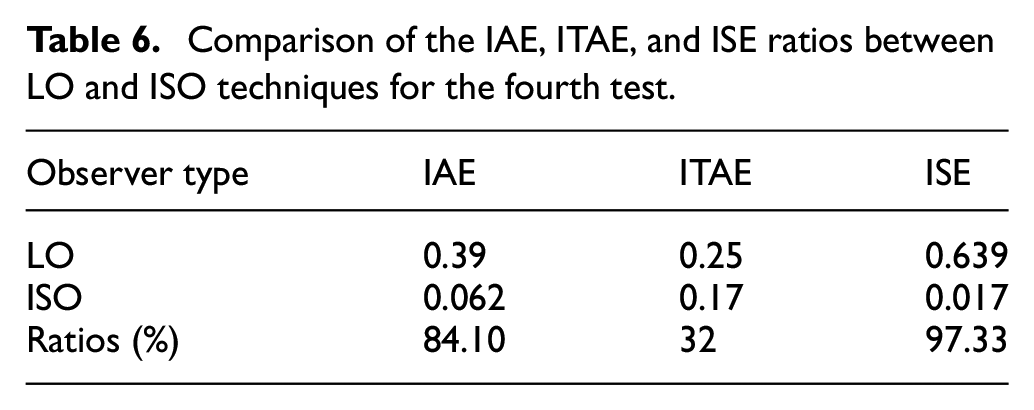
Table 7 presents a comparative analysis between the proposed observer (ISO) and the conventional observer (LO). The results indicate notably favorable outcomes with the proposed approach, including enhanced dynamic responses, minimal sensitivity to speed variations, negligible overshoot, high precision, reduced rise and settling times, superior robustness, and lower values for ITAE, IAE, and ISE.
Comparative outcomes derived from the proposed method in contrast to the conventional one.
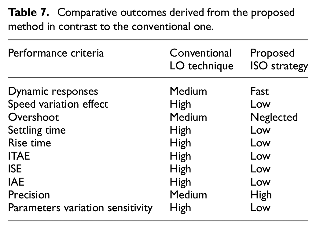
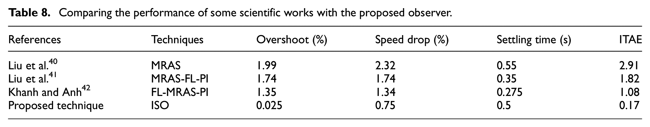
Table 8 summarizes the comparative quantitative performance metrics of the proposed observer and other techniques found in the literature. Simulation results indicate that the proposed ISO technique enhances control performance by minimizing speed drops at the moment the load is applied. It also reduces overshoot during changes in load torque or motor reference speed. Additionally, the ITAE is used as an evaluation criterion to compare the effects of various observer methods on overshoot and steady-state error. A lower ITAE value demonstrates that the proposed observer algorithm tracks the reference speed more accurately than other advanced observer techniques.
Comparing the performance of some scientific works with the proposed observer.
Conclusions
In this study, a speed sensorless control based on an ISO for IPMSM has been proposed and presented. The designed method treats the important negatives of the conventional LO approach such as robustness. The suggested ISO has the advantage of being more accurate, reliable, and easy to use; because it is simple to obtain the observer gain. Moreover, the stability of the closed-loop system has been demonstrated using the Lyapunov theorem when the proposed ISO technique is applied. Simulation results show that the designed ISO outperforms the LO in speed control performance under four conditions, improving the speed IAE by approximately 56.90% in the first test, 54.94% in the second, 89.54% in the third, and 84.10% in the final test. It also outperforms the reconstruct or in no-load conditions, speed fluctuation conditions, low-speed control, and load fluctuation conditions. ISO significantly improves errors in the presence of parameter variations.
In future research, the sensorless control system using the proposed ISO, as outlined in this paper, will be experimentally implemented on an IPMSM. The expected outcome is a sensorless speed control method employing ISO that can be effectively applied in electric vehicles, which often experience significant load fluctuations and motor parameter variations due to weather conditions and operating environments.
Footnotes
Appendix
Declaration of conflicting interests
The author(s) declared no potential conflicts of interest with respect to the research, authorship, and/or publication of this article.
Funding
The author(s) received no financial support for the research, authorship, and/or publication of this article.
Institutional Review Board statement
Not applicable.
Informed consent statement
Not applicable.
Data availability statement
Data sharing not applicable to this article as no datasets were generated or analyzed during the current study.