
Abstract
This paper highlights the significance of digital controllers over analog counterparts, emphasizing the utilization of optimization techniques such as MPC. It explores the benefits of adaptive controllers compared to MPC, showcasing simulations that dynamically adjust controller parameters to accommodate system and environmental variations. Addressing uncertainties, nonlinearities, and time-varying dynamics, the paper employs MPC-DC technique as an adaptive approach aiming to merge the advantages of digital controllers and MPC.The core concept revolves around leveraging the digital controller’s inherent advantages over analog counterparts and enhancing control precision through MPC, particularly in power converter applications. The study introduces a discrete root locus technique for digital controller design, focusing on DC-DC Buck Converters, with subsequent MPC fine-tuning. Demonstrating efficacy, the approach enhances switching converters’ performance, minimizing passive component size and costs while ensuring robust load and line regulation. Moreover, the proposed MPC based digital controller design methodology extends to other switching converters like Boost, Cuk, and Sepic Converters. Finally, the validation via MATLAB/Simulink simulations underscores the efficacy of the proposed model.
Introduction
In previous eras, analog controllers were predominantly employed for regulating switching converters, yet encountered several challenges. Primarily, interfacing analog controllers with computers posed a significant hurdle, necessitating digital conversion for compatibility with computational systems. 1 As digital controllers, they offer advantages in computer interfacing and are adept at executing intricate computations swiftly and accurately. Digital computing platforms enable computations with virtually any desired level of precision, often at minimal additional expense.2,3 For analog computers, as the complexity of the computation increases, there is a rapid increase in the price to obtain a high accuracy. 3
Digital control surpasses the limitations of analog methods in switching converters by providing real-time programmability, advanced algorithms, and seamless integration with communication protocols, facilitating intelligent power management and system-level optimization. 2 This paper uses the discrete root locus technique to analyze the Buck switching converter for the digital controller design. The discrete root locus theory is not as rich as the analog root locus. Buck converters can be front-end converters for battery sources, fuel cells, laptop computers, etc. There are different approaches for designing a digital controller, along with some trade-offs for performance. 4 For this purpose, these are the two basic design approaches: digital redesign and direct digital approaches.
The controller is initially crafted within the continuous domain and subsequently transitioned into the discrete domain, employing a method known as the digital redesign approach. This approach enables the digital redesign of analog controllers, which can be achieved using techniques such as bilinear transformation and matched pole-zero pairs. 5 In this approach, the plant is initially converted into the z-domain in its continuous form. Subsequently, the controller is directly fashioned within the z-domain utilizing the discrete root locus technique. This method allows for the creation of a digital controller employing root locus techniques and state feedback. 5 This method is widely used due to its favorable properties, such as stability preservation, accurate frequency response approximation, and ease. This transformation maps the entire left half of the s-plane to the inside of the unit circle in the z-plane, thus preserving the stability of the system. In this approach, the plant is initially converted into the z-domain in its continuous form. Subsequently, the controller is directly fashioned within the z-domain utilizing the discrete root locus technique. This method allows for the creation of a digital controller employing root locus techniques and state feedback. 5 The digital controller model’s dynamic response is far better than the analog controller model in two-mode Buck and Boost switching converters. 6 Digital controllers are much better in performance and lower in cost than analog controllers. 3 Op-amp passive components are required to implement an analog controller. They are much more flexible and easy to handle the nonlinear control equations. This paper scrutinizes the application of the root locus technique in designing the digital controller tailored for the dynamics of the DC-DC Buck converter. It delves into the intricacies of this method, exploring its efficacy in achieving desired control objectives for the given plant dynamics. Parasitic resistances are also included in the converters’ mathematical model, and their effect on performance has been investigated comprehensively. The general proposed control system is shown in Figure 1 with the digital controller in series with the MPC.
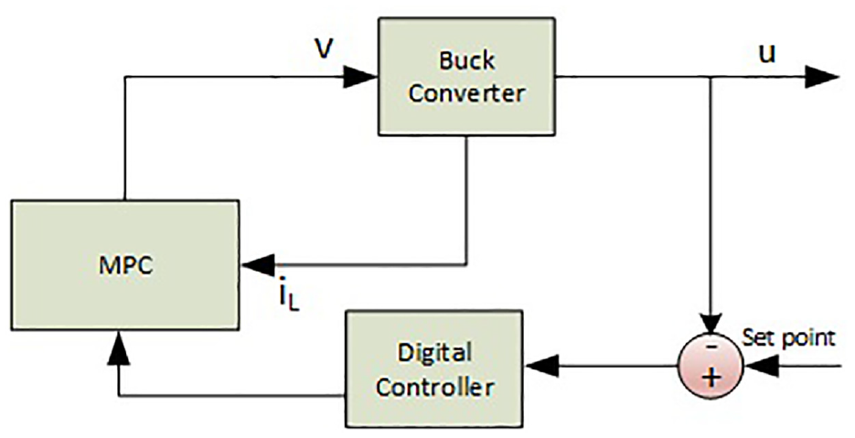
Block diagram of the proposed control system.
The applications of DC-DC Buck converters are diverse, encompassing battery charging for electric vehicles, USB OTG functionality, point-of-load converters for personal computers and laptops, as well as their battery chargers, solar chargers, quadcopters, portable medical devices, telecommunication equipment and brushless motor controllers. This paper introduces an adaptive controller to optimize these applications, ensuring enhanced performance and efficiency.
Control systems come in two flavors: open-loop, where actions are set without adjusting to results, and closed-loop, where feedback provides continuous correction. This particular system employs the latter for precise control. 7 The output response for this system is feedback and generates an error when compared with the input forcing function. The measured response is the response of the physical system, which is compared with the desired response and the difference between them, known as an error, which initiates the action that leads the system towards the desired response. 8 This error may be processed by another physical system known as the filter, controller, or compensator for real-time applications. 9 The digital output signal of the digital controller is applied to the analog plant after converting it into an analog signal using a digital-to-analog converter. Finally, MPC has been used to minimize the error, as discussed in the MPC design section. MPC can also find the optimal control inputs that minimize a cost function subject to some constraints. Still, it only requires a partial knowledge of the system dynamics and future disturbances and references.
After highlighting the benefits of digital converters, there remains ample scope for further refinement in tuning the response of power converters. Initially, traditional methods such as Ziegler & Nichols are employed to adjust PID controller parameters, leading to the fine-tuning of the step response.8,9 Furthermore, Ghith et. al. used some optimization techniques for tuning PID controller parameters especially for micro robotics system.10–14 In recent research, the continuous demand for increased efficiency and performance led to various branches of control, especially in the field of power supplies.15–17 While exploring various control techniques, MPC emerged as particularly well-suited for both educational and industrial applications, as demonstrated in previous studies.18–20 MPC typically involves utilizing a plant model to forecast its future dynamics, followed by solving an optimal control problem at predetermined sampling intervals. 21 The rationale for employing MPC in the realm of control engineering lies in its capacity to tailor controllers for improved performance and to develop precise models for electrical systems.22–25 Although using MPC has many benefits, there are a few things to keep in mind when putting it into practice; MPC often requires many model coefficients to describe a particular response, and many MPC models are formulated for output disturbances only, it is imperative to devise a methodology that is capable of effectively managing input disturbances as well. Moreover, high computational load and high algorithm complexity are also a few drawbacks of using MPC alone. In conjunction with these drawbacks, the advantages include its ability to handle complex and uncertain systems, handle constraints and optimize performance according to a specific cost function, incorporate feedback and feed forward information, and handle external signals to improve tracking and disturbance rejection. In this case, MPC can be easily tuned and modified if the cost function parameters are changed, making MPC the most suitable for controlling the DC-DC Converters where the parameters can be changed anytime. While using MPC alone, a reliable and accurate system model is required; this may not always be available or change over time. Furthermore, it requires high computational power and a fast solver to solve the optimization problem in real time, which may not be feasible for some applications or platforms. In addition, MPC can be unstable if the model is inaccurate or if the disturbance is unpredictable, and it may also be difficult to design and implement a suitable cost function or constraints that meet the desired behavior and trade-offs of the system. In this paper, an adaptive controller is being developed to mitigate these limitations by seamlessly adapting to system and environmental variations, thereby dynamically adjusting controller parameters.
Insights into buck switching converter modeling
Buck converters are essential to contemporary power electronics and are being studied extensively in a number of R&D projects. Because of their capacity to effectively step down regulated voltage levels, 26 these converters are used extensively in a wide range of applications. Consequently, they are essential parts of power supplies, battery charging systems, electric vehicles, renewable energy systems, and more. Furthermore, new developments in control strategies, integrated circuit design, and optimization methodologies have resulted from advances in Buck converter technology, augmenting their adaptability and suitability across diverse sectors. The general Buck converter circuits consist of a switching device, which may be a BJT, MOSFET, or any switching device, diode, and combination of Inductor, Capacitor, and load resistance 27 as shown in Figure 2. The circuit operation can be divided into two modes when the switching device is in ON and OFF conditions.
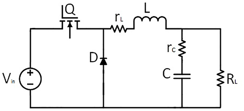
DC-DC buck converter.
The transfer function for above mentioned Buck converter is shown in equation (1).
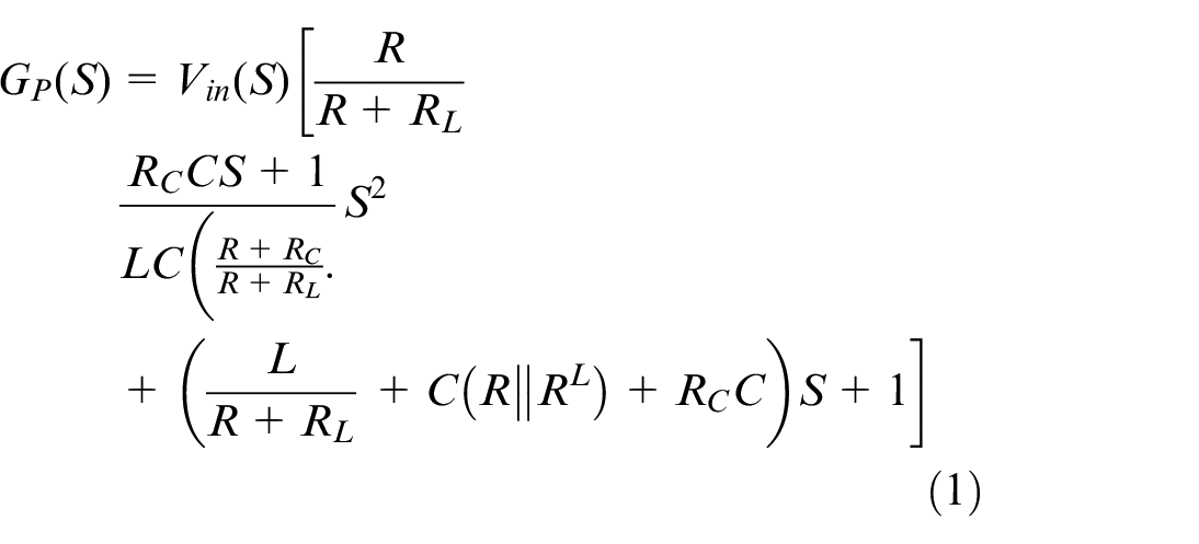
In the circuit configuration, the symbol
Methodology
After obtaining the transfer function of the Buck converter, the position of the point z is determined based on specified criteria such as sampling time, settling time, and damping ratio. Subsequently, the response of the uncompensated system is evaluated, following which the digital controller is integrated into the loop to enhance system performance. For this purpose, the analog plant converts into the z-domain for designing the digital controller.28,29,30,31 Zero controllers are placed that will cancel the effect of the pole of the plant. After placing the zeros of the controller, the exact location for the pole placement is determined accurately by the angle condition, which fulfills the required specifications. Gain for the digital controller is also found by the magnitude condition. After finalizing the design of the digital controller, the response of the compensated system is evaluated. Subsequently, MPC is employed to further optimize the system’s performance. Additionally, line and load regulation tests are conducted on the compensated system to demonstrate the effectiveness of the technique. The process of designing a digital controller to minimize errors using MPC is encapsulated in the following Figure 3.
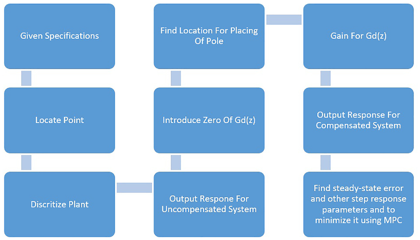
Steps for designing the digitally optimized controller.
Digital controller design for Buck converter
In order to design the digital controller effectively, it is imperative to have accurate values for the transfer function parameters. These values play a crucial role in evaluating the performance of both uncompensated and compensated systems for the chosen Buck converter. The following parameters are employed in the design of the digital controller for the transfer function of the DC-DC Buck converter.
For the value of load resistance R using simple ohms law at the output voltage and current is 5/1.2 = 4.17
Put all the parameters in equation (1) and get as in equation (2).
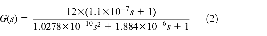
Here, before following the flow chart in Figure 3 as shown above to design the digital controller check the uncompensated response for the Buck converter. The need to check the uncompensated response is to realize the actual response of the plant which requires betterment. The step response and the pole zero map for the dc-dc Buck converter are shown in Figure 4.
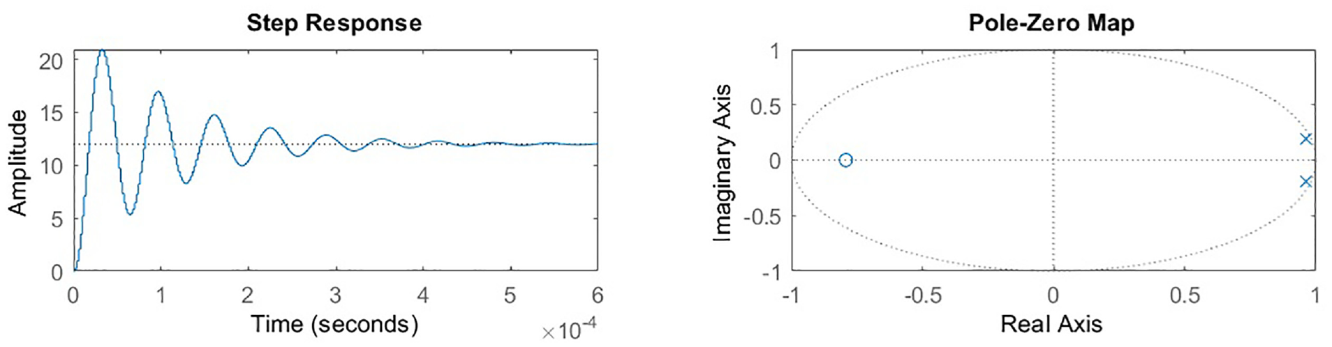
Step response and PZ map.
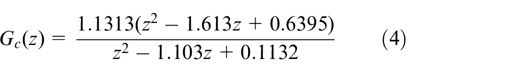
Following the flow chart depicted in Figure 3, the design process for the digital controller of the aforementioned uncompensated system, which is a DC-DC buck converter, is outlined in equation (3).
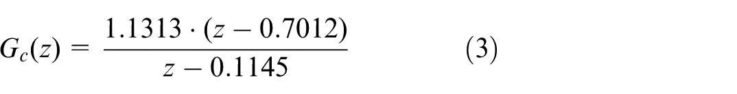
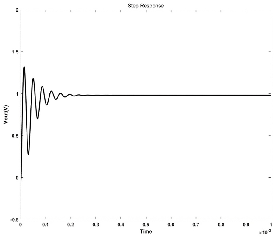
So, the digital controller as in (4) is designed for the Buck converter and the compensated step response for the Buck converter is shown in Figure 5.
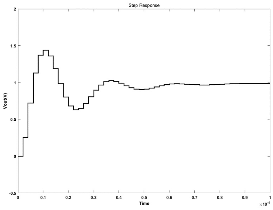
Step response for the compensated Buck converter.
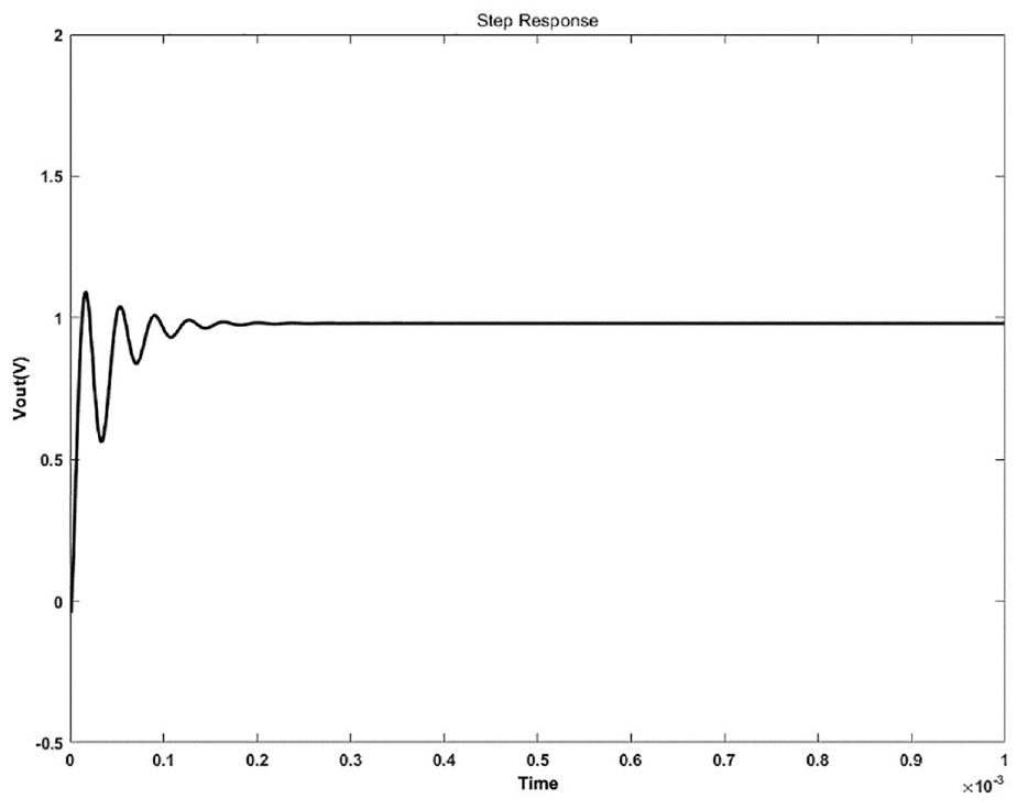
In this analysis, a steady-state error is evident, suggesting room for improvement in the rise time, settling time, and percentage overshoot. To address these issues, an optimized MPC controller is deployed with the aim of reducing the steady-state error and enhancing other key parameters observed in the step response. Finally, the optimized controller for the Buck converter is shown in equation (4) and the step response for the optimized system is shown in Figure 6.
Step response with optimized controller for Buck converter.
The step response of the Buck converter with the optimized controller nearly approaches the desired level, exhibiting minimal steady-state error, as illustrated in Figure 6. Hence, this response constitutes the conclusive findings of this specific research endeavor.
MPC controller design for Buck converter
After acquiring the output from the digital controller for the DC Buck Converter mentioned earlier, additional refinement is accomplished through MPC, as illustrated in Figure 7. This effectively highlights the fundamental operational principle of MPC in the context of switching converters, underscoring its pivotal role in optimizing control strategies and enhancing system performance.
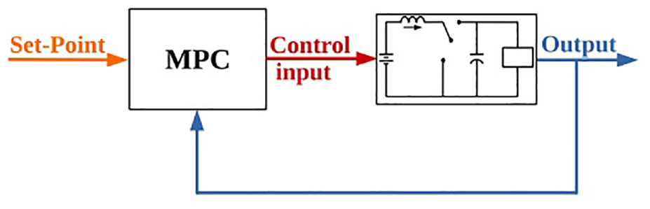
Working principle of MPC for switching converters.
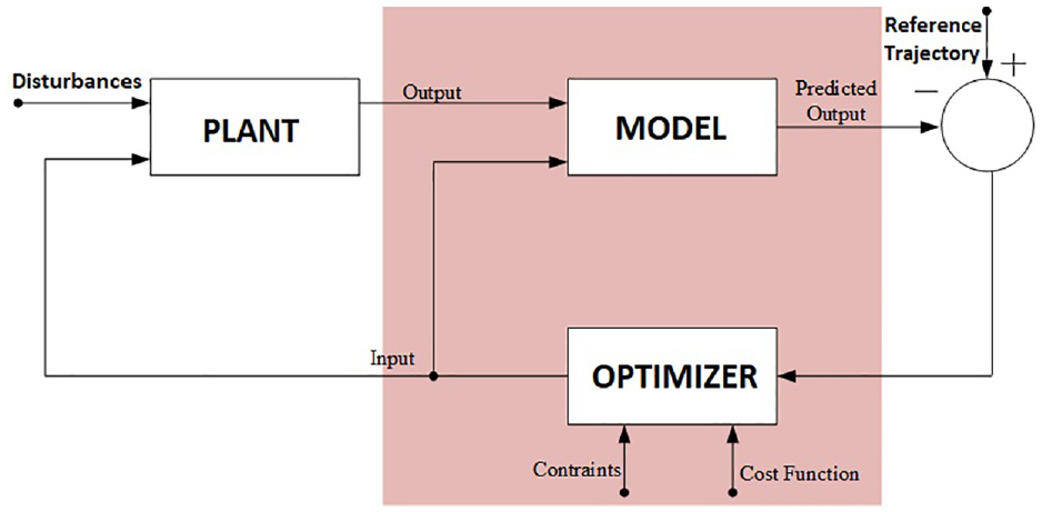
Additionally, the efficacy of MPC is highlighted in Luca et al. 32 Furthermore, in the paper33,34 the authors introduced the concept of MPADRC & MPSMC and showcased the integration of MPC with ADRC & SMC respectively, which include the inner current loop. This innovative approach combines the strengths of both MPC and ADRC to address control challenges in power electronics systems, highlighting its efficacy in achieving robust and adaptive control performance. The MPC block diagram is illustrated in Figure 8. The key steps in MPC involve solving the finite-horizon and optimal control problem by predicting future behavior and estimating the current state of the plant.21,35
MPC Block diagram.
The fundamental concept of MPC revolves around selecting a model of the system and then predicting and optimizing its future behavior through the following steps.
Formulation of a state model.
Following the formulation process, it is imperative to acquire the measurements of all the states within the system.
Next, minimizing the specified cost function within a given prediction and control horizon is necessary while also ensuring that the provided constraints are met.
This will continue in a cycle until new state measurements are available.
MPC is a control strategy that iteratively solves an optimization problem over a finite time horizon to determine the control actions that minimize a cost function while satisfying constraints. This iterative process allows MPC to anticipate future changes in the system and adjust the control inputs accordingly, making it particularly suitable for systems with constraints and uncertainties. By continuously updating the control actions based on new measurements and predictions, MPC can achieve better performance and robustness compared to traditional control methods.
Simulation results
For investigative purposes, the performance of both the compensated and uncompensated systems, as well as the optimized controller for the Buck converter, is presented below. Initially, the uncompensated system for the Buck converter is simulated, revealing a sluggish response, as depicted in Figure 9.
Uncompensated system for Buck converter.
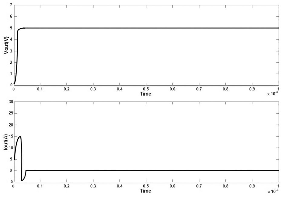
Consequently, the implementation of a controller is warranted to enhance the response. For simulation purposes, a specific example is selected to evaluate the response of the compensated system. According to the design specifications, the output voltage for the DC-DC Buck converter is set to 5 volts from a high-level input of 12 volts. Equation (3) is derived by incorporating all relevant parameters into the transfer function for the Buck converter, followed by the design of a digital controller as depicted in equation (4). Subsequently, the designed controller, in conjunction with the DC-DC Buck model, is applied to obtain the desired results. To proceed, the given circuit is simulated as illustrated in Figure 10. In the simulation results depicted, the desired output voltage for the DC-DC Buck converter, set at 5 volts from an input level of 12 volts, is showcased. The attained output voltage and current are visualized in Figure 11, confirming the attainment of the specified output level.
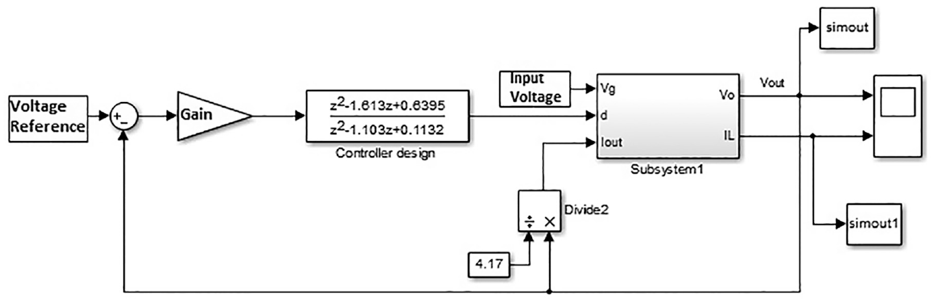
Designed controller for Buck converter.
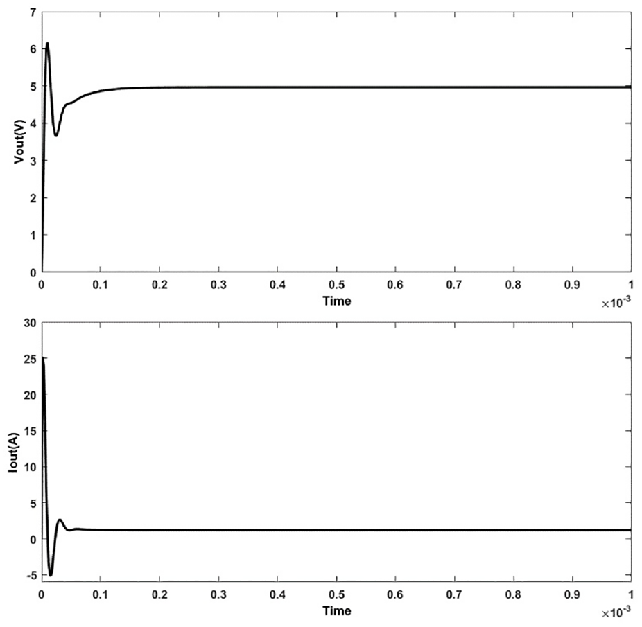
Output voltage and current without ADC Block.
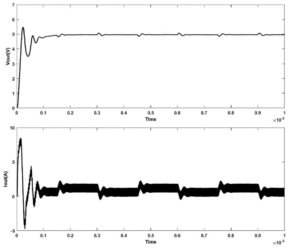
In the provided simulation and the expected outcome for the output voltage, the absence of an ADC block is notable. For enhanced practicality, the inclusion of an ADC block is imperative. The corresponding results are illustrated in Figure 12. Introducing the ADC block introduces a certain time delay, emphasizing the significance of implementing optimized techniques to address this delay effectively.
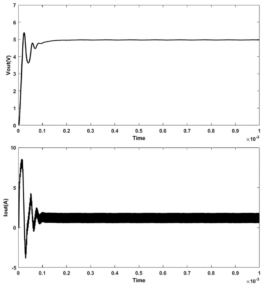
Output voltage and current with ADC Block.
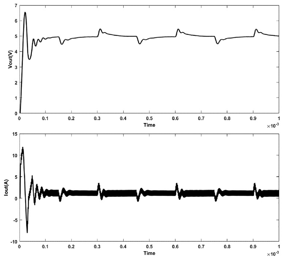
Finally, the MPC is applied as discussed earlier to further refine the output voltage and the output current of the said DC-DC Buck converter. The response below in Figure 13 using MPC can be seen as much more practical as compared to the above two that is, the simple Buck converter and the response of Buck converter with ADC block. Additionally, the load regulation is shown in Figure 14, while the line regulation is illustrated in Figure 15, which clearly shows the stability of the compensated buck converter for load and line regulation respectively. Firstly, the variation in load is taken as the disturbance effect, and finally, the input variations are taken into account and the regulation is monitored.
Output voltage and current using MPC.
Buck converter load regulation.
Buck converter line regulation.
Discussions and analysis
This section highlights the efficacy of MPC followed by the adaptive controller proposed in this study. MPC offers a significant advantage over other robust controls by ensuring system stability and performance amidst uncertainties, disturbances, and modeling errors. Moreover, it can accommodate constraints and optimize system performance while adapting to changes through updated measurements and predictions. However, MPC may necessitate greater computational resources and a more accurate model compared to adaptive control methods. Recognizing the limitations of MPC, an adaptive controller has been devised to address these challenges. This adaptive approach dynamically adjusts controller parameters in response to system and environmental changes, effectively managing uncertainties, nonlinearities, and time-varying dynamics. Nonetheless, there exists a trade-off between handling constraints and optimizing system performance.
Conclusion
The direct method for digital controller design is employed for the DC-DC Buck switching converter, in conjunction with the advanced optimization technique MPC. In this approach, the Buck switching converter is first transformed into the z-domain. Subsequently, MPC is applied following the digital controller, showcasing superior results compared to conventional methods. This research addresses the tradeoff inherent in digital-to-analog and analog-to-digital conversion delays through the utilization of MPC. This composite technique holds significant promise for digitally optimized controller design of DC converters. To achieve optimal outcomes, it is crucial to incorporate key parameters such as sample time, prediction horizon, and control horizon. Furthermore, this paper discusses shortcomings associated with MPC and demonstrates the enhanced effectiveness of the proposed adaptive controller over MPC alone. Ultimately, simulation results underscore the effectiveness of the MPC-DC technique.
In future work, certain limitations regarding the MPC and digital approach can be addressed. These include the need for a reliable and accurate system model, as well as the requirement for high computational power and a fast solver to solve the optimization problem in real time, which may not be feasible for some applications or platforms.
Footnotes
Acknowledgements
The authors would like to extend their sincere appreciation to the Researchers Supporting Project (RSPD2024R752) King Saud University, Riyadh, Saudi Arabia.
Declaration of conflicting interests
The author(s) declared no potential conflicts of interest with respect to the research, authorship, and/or publication of this article.
Funding
The author(s) disclosed receipt of the following financial support for the research, authorship, and/or publication of this article: This research was funded by Researchers Supporting Project number (RSPD2024R752), King Saud University, Riyadh, Saudi Arabia.
Data Availability Statement
Data sharing not applicable to this article as no datasets were generated or analyzed during the current study.