
Abstract
The magnetic levitation ball system is characterized by strong nonlinearity, multiple disturbances, and intrinsic instability, which has long been a thorny problem in the field of control engineering. The magnetic levitation system can be continuously and stably levitated, even in a complex environment. In this thesis, the model of the magnetic levitation ball system is firstly constructed according to the kinetic theory and simplified according to the actual situation. After that, a linear active disturbance rejection control (LADRC) controller for the magnetic levitation ball system is designed. Considering that there are many parameters in the LADRC controller and it is difficult to obtain the optimal control effect by manual tuning, an adaptive variable gain LADRC algorithm is proposed to optimize the control strategy of LADRC parameters. An adaptive iterative algorithm is used to adaptively adjust the bandwidth of the linear extended state observer (LESO) in LADRC, and the convergence of the algorithm is demonstrated by using the Lyapunov function. To solve the problem that the proportional and differential gains of the LADRC controller can only be adjusted unidirectionally and simultaneously, this paper proposes an error variable gain algorithm. The aim is to realize the non-unidirectional and more detailed adjustment of the controller parameters, and it is rigorously analyzed and demonstrated through simulation and experiment. The results show that the proposed algorithm is better than proportional–integral–derivative (PID), sliding mode control (SMC), and LADRC in terms of dynamic performance, steady-state performance, and anti-interference.
Keywords
Introduction
Magnetic levitation technology, with its advantages of frictionless, lubrication-free, and low power consumption, has received wide attention from researchers.1–3 The magnetic levitation system possesses some characteristics such as strong nonlinearity and open-loop instability. 4 The technology is widely used in magnetic levitation trains,5–7 magnetic levitation bearings,2,8,9 medical equipment,10,11 and other fields. In the suspension control algorithm, closed-loop feedback control is necessary because the system possesses open-loop instability. 12 The core of research on maglev technology is the study of maglev control algorithms. Due to the discovery of magnetic materials and the rapid advancement of contemporary magnetic.
A great number of algorithms with excellent performance have been proposed, such as fuzzy contro,13–15 robust control, 16 neural network algorithms, 17 adaptive algorithm, 15 etc. In engineering practice, algorithms that do not rely on specific mathematical models such as PID, 18 SMC,19,20 and ADRC21–24 show excellent performance in suspension control. ADRC was created by Prof. Han in 1998 to break the limitations of PID algorithms. ADRC is unique in that it assigns all the uncertainty of the controlled object to the part of the unknown disturbance. The required coefficients are then estimated and compensated based on the system’s extended state observer data. 25 Based on ADRC, Prof. Gao et al. 26 applied the concept of frequency scale and created LADRC, which relates the controller and observer parameter adjustment to bandwidth. Abbreviating the adjusted parameters to three makes LADRC popularized a lot. However, he did not analyze and discuss how the parameter affects the system response. Parameter tuning is an extremely critical aspect of the application of LADRC. Chen et al. calculate his controller bandwidth and observer bandwidth values by assuming a known relationship between the two parameters and the regulation time. 27 However, the regulation time parameter assumed by this method needs to be repeatedly verified to obtain a superior value. Wei et al. proposed a time-varying active disturbance rejection control (TADRC) method by varying the action time of the LESO in the steady state and transient state, and presented a set of parameters tuning procedures. 28 However, adjustment of the parameters in this method is required to be continuously manually adjusted throughout the process to obtain satisfactory performance. Humaidi et al. proposed to use of the particle swarm optimization (PSO) algorithm to rationalize the parameters of LADRC. A smaller variance of system error and better steady-state performance are obtained. However, the algorithm produces excessive overshooting and poor dynamic performance. Chen et al. 29 put forward an ADRC parameter adaptive method according to Q-learning. After using this algorithm, the system presents good robustness and high accuracy, but no suitable performance metrics are used for evaluation. Liu et al. 30 figured adaptive LADRC in conjunction with the pole configuration technique. The method can reduce the tunable parameters to two, but the rest of them are still not easy to adjust. Li et al. 31 investigated a measurement delay compensation LADRC and proposed a simple method for LADRC parameter adjustment. Ouyang et al. 32 proposed an adaptive LADRC control algorithm to solve the problem of the controller’s inability to adjust parameters in real time. A-LADRC has good robustness and dynamic performance, but the controller parameters and the observer parameters can only be tuned simultaneously in one direction. To maintain the air gap between the electromagnet and the track, Sun et al. proposed a neural network-based supervisor control approach to realize effective control for the scenarios of random disturbance force, flexible track, and time delay of maglev vehicle systems. 33 Wang and Yu proposed an optimized position accuracy control method for magnetic levitation systems based on an adaptive resonant equivalent input disturbance observer to improve the multiple disturbance suppression of magnetic levitation systems under unknown frequency resonant disturbances. Compared with the existing methods, it can observe the unknown frequency resonant disturbance, which improves both position accuracy and disturbance suppression. However, the effect of noise in practical applications is not considered in this method. 34
In addition, this paper is inspired by the paper of Sun et al. in terms of innovative applications of the LADRC algorithm. The work they have done has advanced the development of LADRC.35–40 Due to the many parameters that need to be adjusted in the LADRC controller, it is difficult to achieve the ideal working conditions by completely manual adjustment. To be able to adaptively adjust the parameters of the LARDC controller to a certain extent, and to be able to flexibly fine-tune the parameters according to the actual needs, this thesis innovatively found that the proportional gain and differential gain can only be adjusted simultaneously in one direction. At the same time, to avoid the problem that the proportional gain and differential gain can only be adjusted unidirectionally at the same time, this thesis innovatively discovered an AVG-LADRC algorithm, which is used to solve the above problems. By using the proposed algorithm, the stable levitation of the magnetic levitation ball system is successfully realized. Through simulation and experimental verification, it is thus demonstrated that the AVG-LADRC algorithm outperforms several other algorithms in comparison in terms of control metrics under different reference signals. The structure of the paper is organized as follows: Chapter 2 establishes the nonlinear mathematical model of the magnetic levitation ball system. Chapter 3 designs, derives, and proves the algorithm, and Chapter 4 is the system simulation. Chapter 5 contains the experimental validation, and Chapter 6 includes the conclusion and future research plan.
Nonlinear model of magnetic levitation ball system
System introduction
The block diagram of the system is shown in Figure 1. The experimental equipment in this thesis is a pull-up magnetic levitation system in which the steel ball is controlled by an electromagnetic force only in the vertical direction. The measurement module, control module, and drive module are the main modules to form the system. The measurement module measures the displacement between the steel ball and the electromagnet utilizing the laser displacement sensor and converts the displacement data into a 0–5 V analog displacement signal as input to the control module. The control module contains a preset control law that outputs timely control commands based on real-time position information. The drive module mainly regulates the excitation current of the electromagnetic coil according to the control commands output from the controller, so that the electromagnetic force generated by the electromagnetic coil is balanced by the force on the ball, realizing the stable levitation of the single-degree-of-freedom maglev ball system.
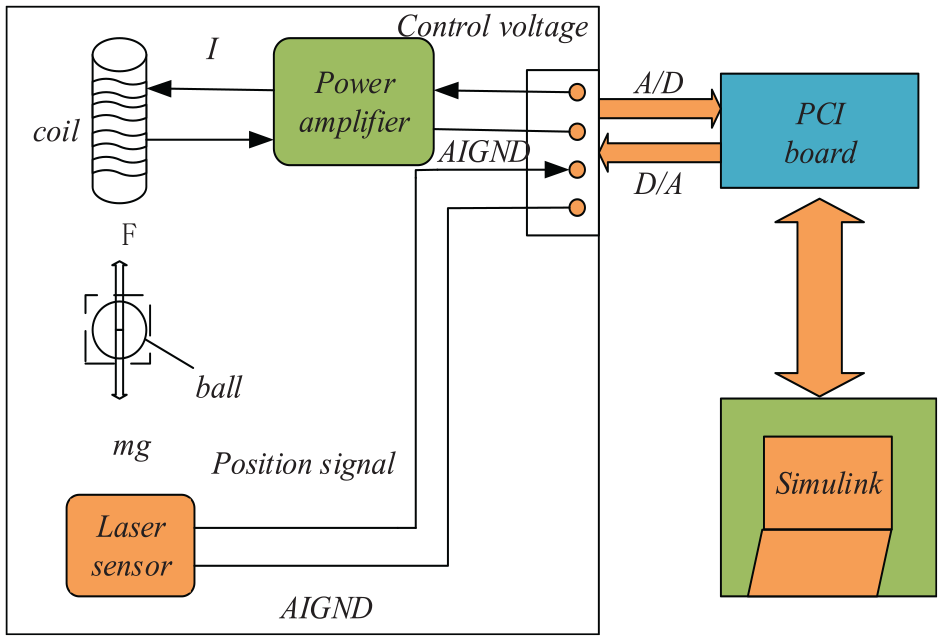
Structure of magnetic levitation ball system.
Model of magnetic levitation ball
To simplify the analysis, without affecting the system performance analysis, some influencing factors will be explained.
(1) Ignoring magnetic eddy currents, leakage, and hysteresis factors;
(2) Assuming uniform distribution of the magnetic field in the air gap and uniformity in the hands of the blob;
(3) Neglecting the magnetoresistance of the ball and the solenoid coil;
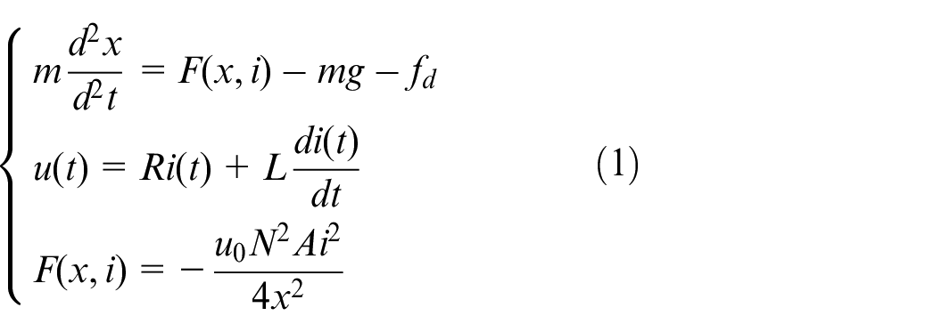
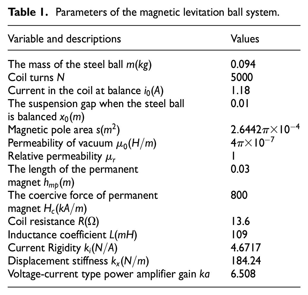
Set up a system of equations based on Newton’s second law, the law of electromagnetic induction, and Kirchhoff’s law. As shown in equation (1). The parameter values are shown in Table 1. The parameter
Parameters of the magnetic levitation ball system.
The system has strong nonlinear and multiple equilibrium states, so the system equilibrium boundary conditions are introduced to constrain it. After ignoring as much as possible the external perturbations, we can obtain that the system boundary equation is shown in equation (2).

At this point
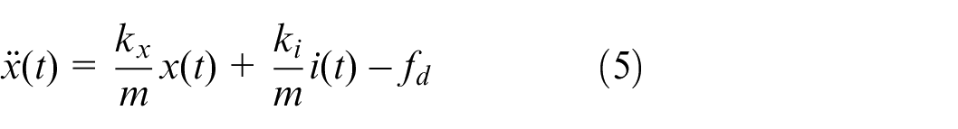
It will be in a state of falling or adsorption of electromagnets. If it is within the range of controllable disturbance, the magnetic suspension ball control algorithm can overcome the impact of the disturbance, and continue to stabilize after a slight positional shift. Taylor expansion of
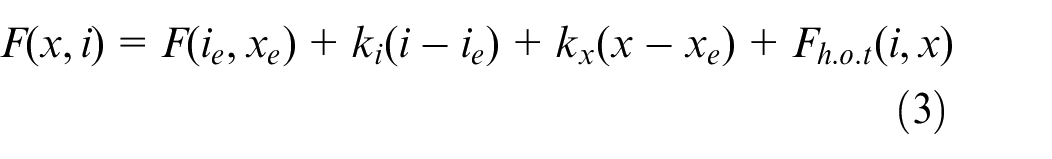
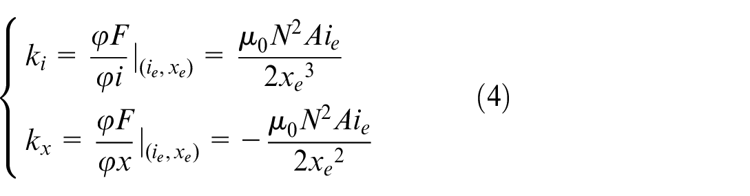
Substituting equation (1) into (3), the equation describing the system is shown in equation (5).
To facilitate the system analysis as well as the construction of the controller, a power amplifier is used to solve the driving problem of inductive loads, and the driving module of the system is chosen to use a voltage-current type power amplifier. This power amplifier has a linear relationship within a certain range, and its dynamic characteristics are shown in equation (6).
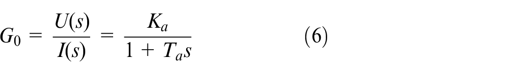
where
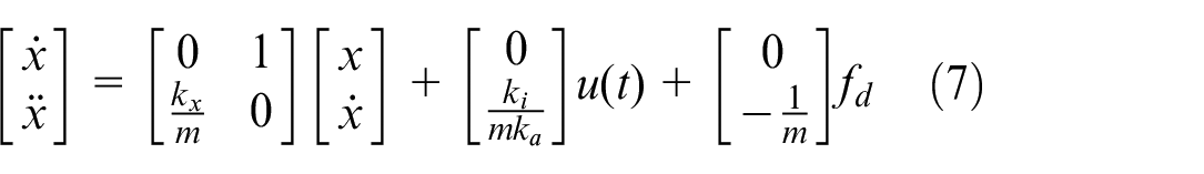
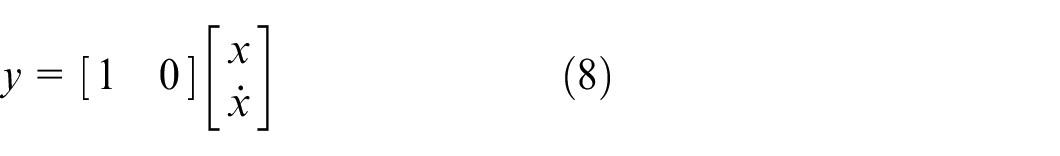
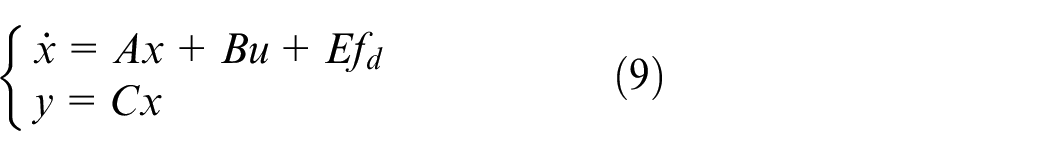
To analyze the structure of the system in depth, equations (7) and (8) are simplified to the basic form of the state space. As shown in equation (9):
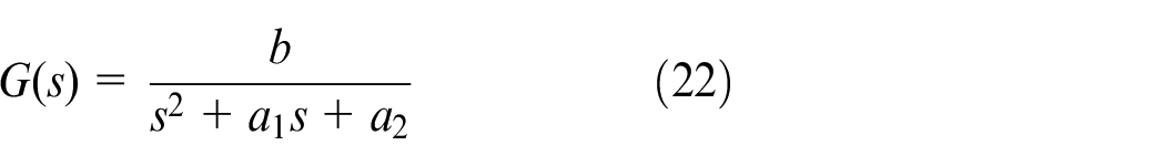
The transfer function equation for the magnetically levitated ball system is derived from equation (9) as shown in equation (10).
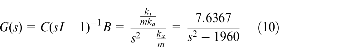
Substituting specific parameters from the physical model into the transfer function of the magnetically levitated ball system, the open-loop position response curve of the system under a step signal is obtained in MATLAB. It is easy to conclude that the curve of an electromagnetic levitation open-loop system diverges under the action of a step signal. Thus, the system is intrinsically unstable. Therefore, the system must use closed-loop feedback control.
Control strategies and parameter tuning
Structure of LADRC
The reasons for choosing LADRC for the Maglev ball control system are mainly the following: Firstly, LADRC is inherently resistant to external disturbances and also has the characteristic of not relying on accurate mathematical models; secondly, LADRC is highly robust and can effectively deal with uncertainties and disturbances in the magnetic levitation system. Finally, LADRC can improve the dynamic performance of the system, which can effectively reduce the overshoot and settling time, so that the magnetic levitation system can respond quickly and maintain high-precision levitation.
There are several reasons for not choosing PID or SMC for a magnetic levitation ball control system.
First of all, the magnetic levitation system has significant nonlinear characteristics, such as the nonlinear relationship between the electromagnetic force and the position. PID controller is designed assuming that the system is linear, which makes it difficult to handle these nonlinear characteristics. Meanwhile, the saturation effect of the electromagnetic coil is also a nonlinearity that may cause the PID controller to fail to control the system accurately. Secondly, the dynamic response of the maglev system is very fast and requires fast control actions to maintain stability. The tuning of the PID controller may not be able to meet this fast response demand. When faced with a rapidly changing system, the PID controller is prone to introduce delays and oscillations that can affect the stability of the system. Finally, magnetic levitation systems often require very high control accuracy to maintain stability of the levitated object in a precise position. PID controller may not perform well when dealing with high precision control, especially in the face of large perturbations and noise.
Although sliding mode control (SMC) has strong robustness and disturbance resistance, there are some limitations and challenges in maglev control systems. First, the common high-speed switching behavior in the SMC control law leads to high-frequency oscillations in the system, which is particularly detrimental to magnetic levitation systems. Shaking vibrations not only affect the stability of the levitated object, but also may cause wear and damage to the system’s mechanical components and electromagnetic coils. Second, although SMC is theoretically robust to system uncertainties and modeling errors, it is still difficult to completely eliminate these errors in practical applications. Modeling errors and unmodeled dynamics may introduce additional complexity and affect the performance of the SMC. Finally, designing a sliding mode controller requires careful selection of the sliding mode surface and control law, as well as a detailed stability analysis. This requires a high level of expertise and experience, adding to the complexity of controller design and implementation.
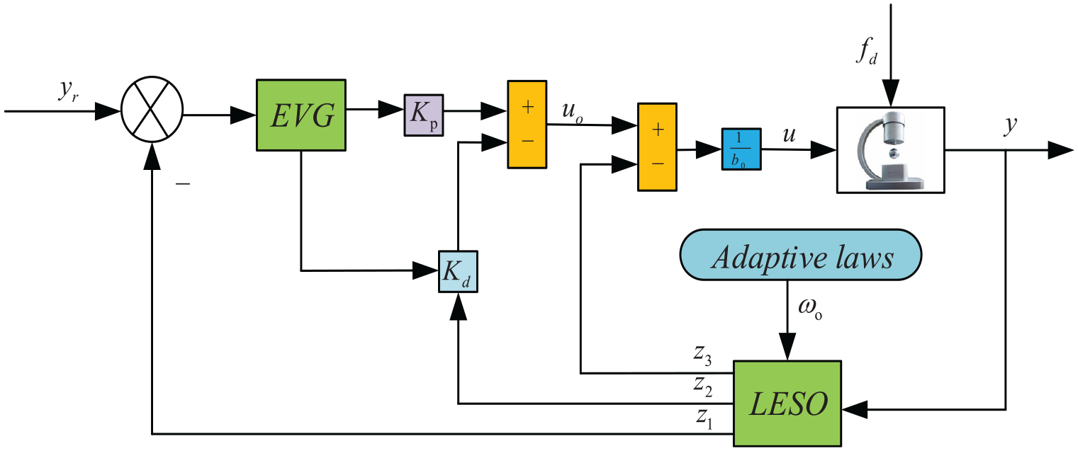
This enables LADRC to provide more stable and efficient control performance in the face of common challenges in maglev systems. The structure of LADRC is shown in Figure 2.
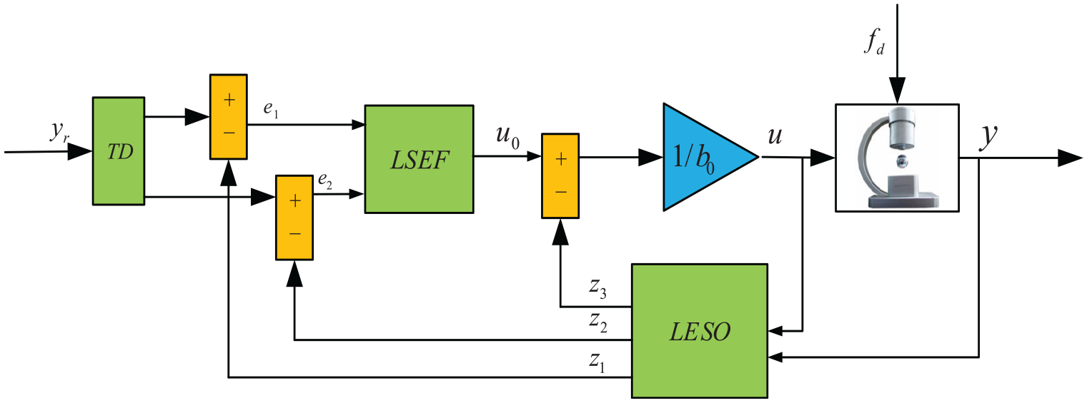
The structure of LADRC.
In LARDC,
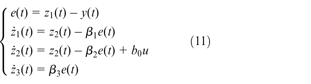
In equation (11),
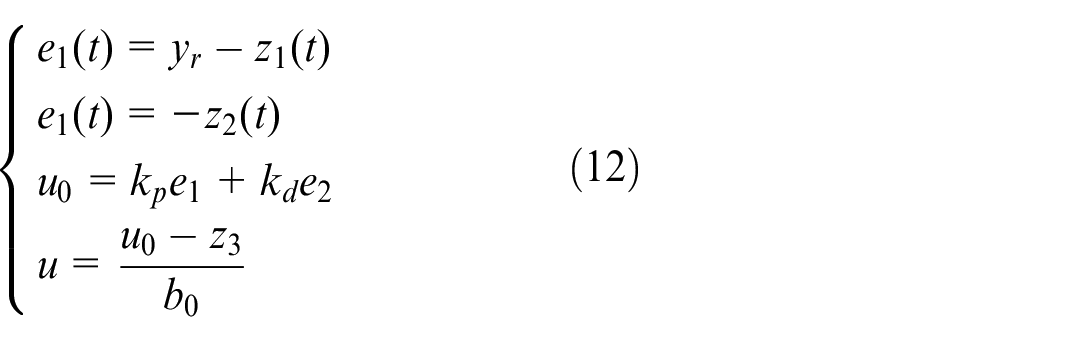
These factors can be defined as follows:

Design of AVG-LADRC
The AVG-LADRC structure composition is shown in Figure 3. This thesis takes the LADRC algorithm framework as the core and introduces an adaptive iterative algorithm to adaptively adjust the extended observer bandwidth parameter
The structure of AVG-LADRC.
Adaptive iterative algorithm
The adjustment of parameters occupies a very important position in the control algorithm, and it is also the key to realizing accurate control of the system. Due to the increase in the number of parameters being adjusted, the workload and work difficulty of engineers and technicians adjusting the parameters have increased dramatically. If a part or all of the system parameters can rely on the design of the adaptive rate, autonomous online adaptive adjustment of parameters, it is bound to bring great improvement to work efficiency. It can largely save the time of adjustment.
In LADRC, the method of manually adjusting the expansion observer bandwidth is tedious. In this thesis, the expansion observer bandwidth is combined with the adaptive rate for online adaptive adjustment of the parameter

The weight update formula is as follows:
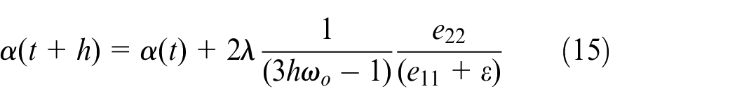
The adjustment factor
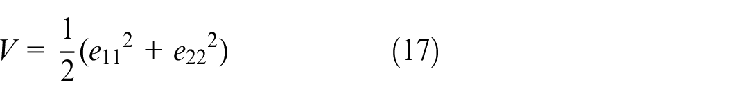
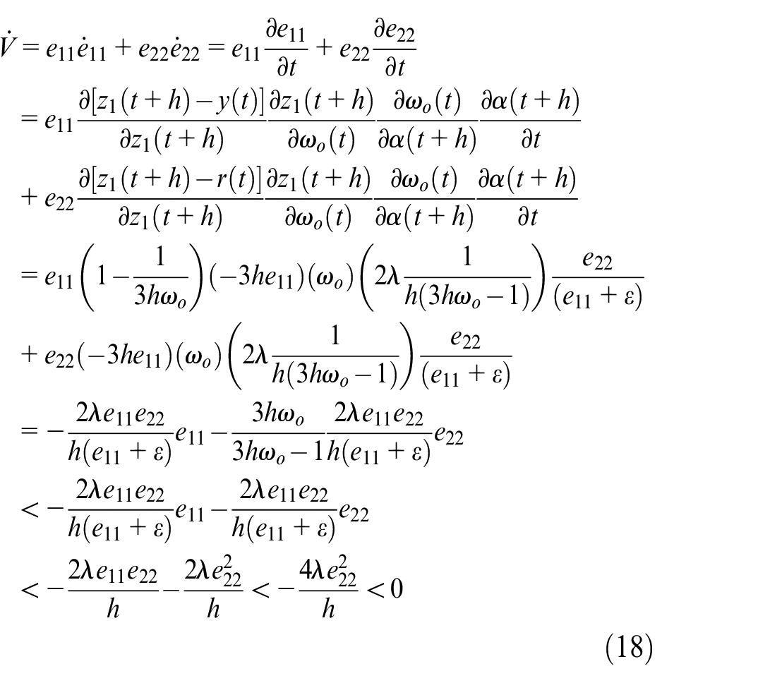
It is easy to conclude from the formula that the chosen function is positive definite. Next, prove its derivative is a negative definite function. The proof procedure is shown in equation (18).
According to the verification of many simulations, we can get the initial value range between 3 and 4, and get the relationship between the initial value of the algorithm and the adjustment coefficient.

Error variable gain algorithm
The error variable gain algorithm is represented as shown in equation (20).
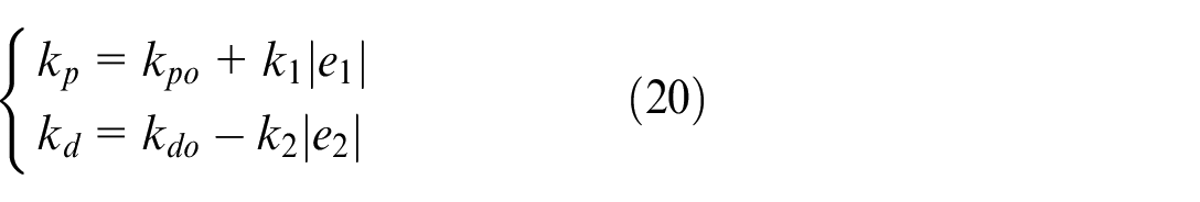
In the nonlinear feedback portion of the LADRC, the proportional and differential gain coefficients are poorly determined. Although they are both adjusted by the system response according to the magnitude of the error in the feedback, the problems that currently exist cannot be ignored. When the error is very large, a large proportional gain can make the system quickly adjust, and the system response speed can be improved, but it will make the system overshoot too much. The differential gain is very sensitive to the speed change of the system error and has an amplifying effect on the system noise disturbance. When the system error increases, under the influence of the proportional gain, the system regulation is very fast. At this time, if the given differential gain is very large, it is bound to hurt the system.
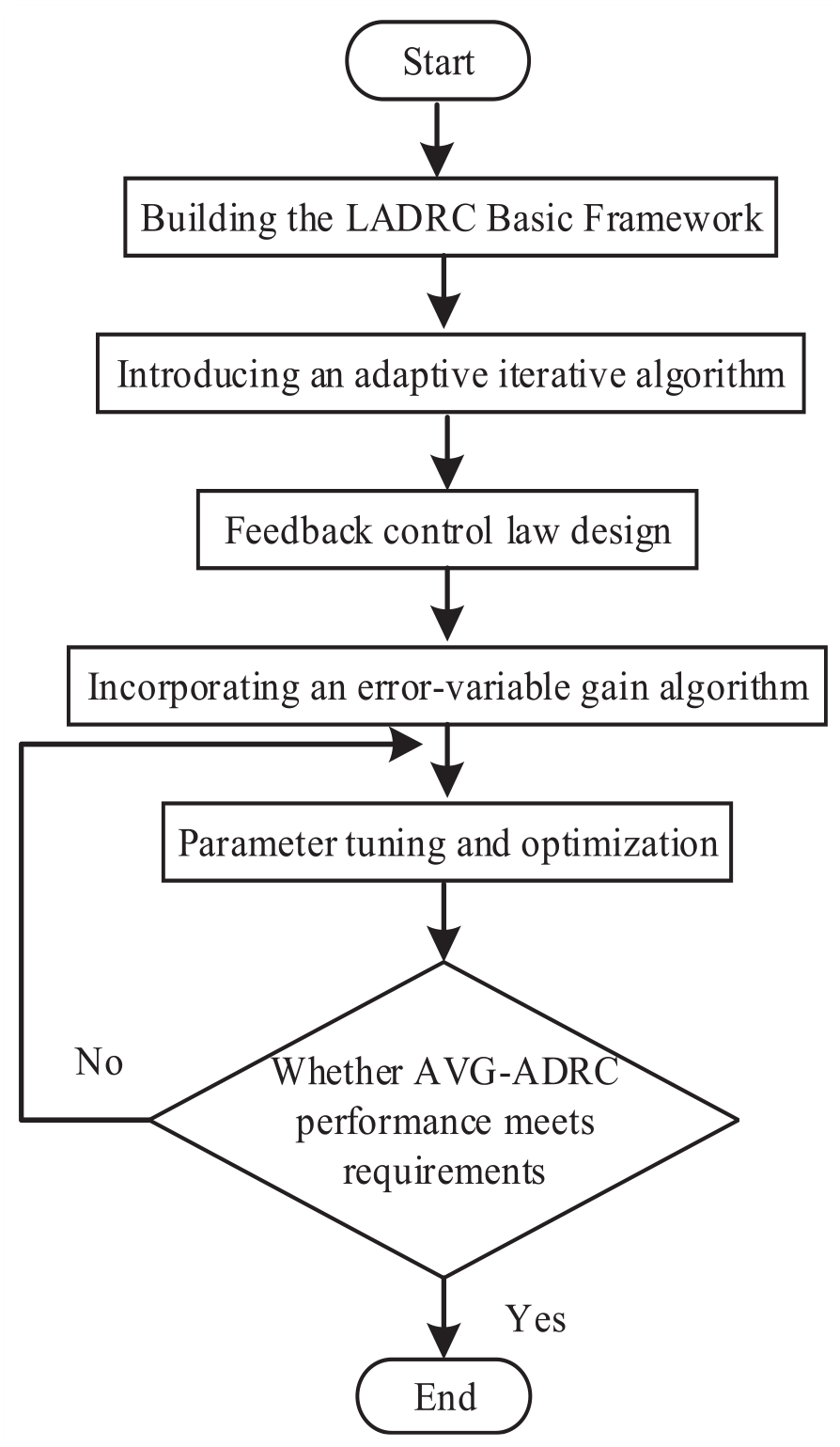
In this thesis, an error-variable gain algorithm is introduced to solve the problem of difficult parameter tuning. It can increase the proportional gain with the increase of error and decrease the differential gain with the increase of error. It can effectively solve the problem that the gain of the LADRC controller can only be increased or decreased at the same time. This method effectively solves the problem that the parameters can only be adjusted in one direction and realizes the fine-tuning of the parameters. The AVG-LADRC implementation flowchart is shown in Figure 4.
Structure of magnetic levitation ball system1.
Let the expression of the second-order system with single input and single output be shown in equation (21).

where
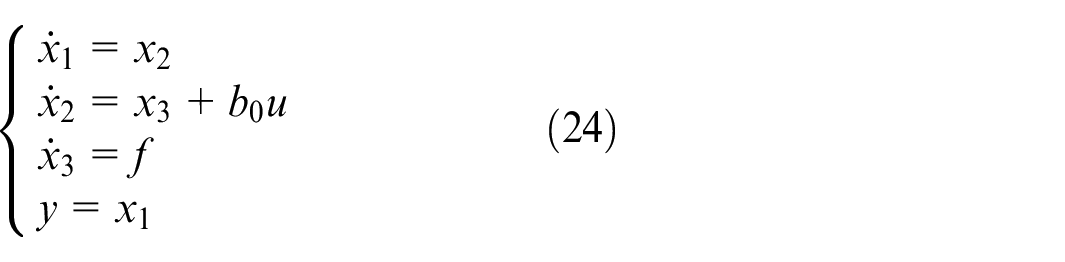
Define the total system disturbance as shown in equation (23).

where
For ease of proof, transform equation (11) form. Let, to obtain the equation of the state of LESO as shown in equation (25).
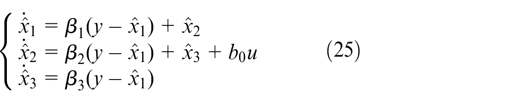
Where
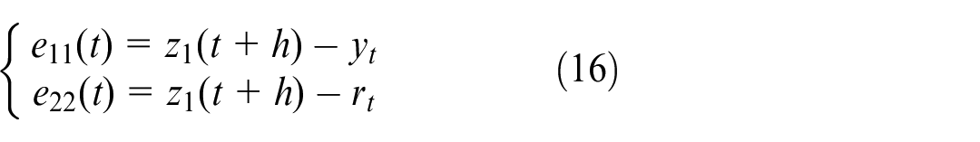
Define the tracking error of the input and output of the system
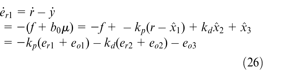
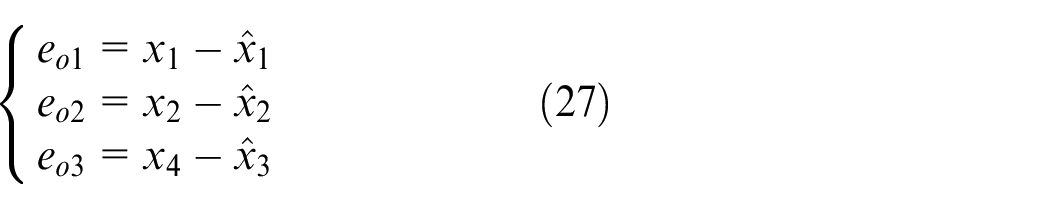
The observation error defining the dilated state observer is shown in equation (27).
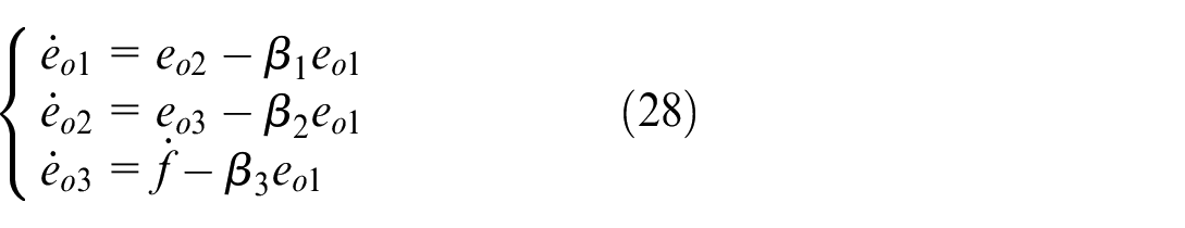
Based on equations (24), (25), and (27) the differential form of the observation error is derived as shown in equation (28).
Equation (29) is derived from equations (23) and (24).

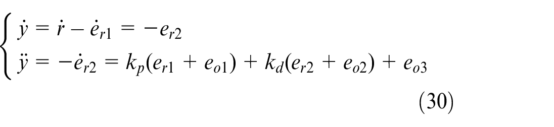
Equation (30) is derived from equation (26)
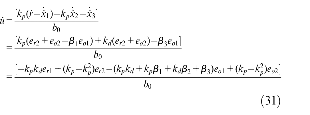
Equation (31) is derived from equations (25)–(27).
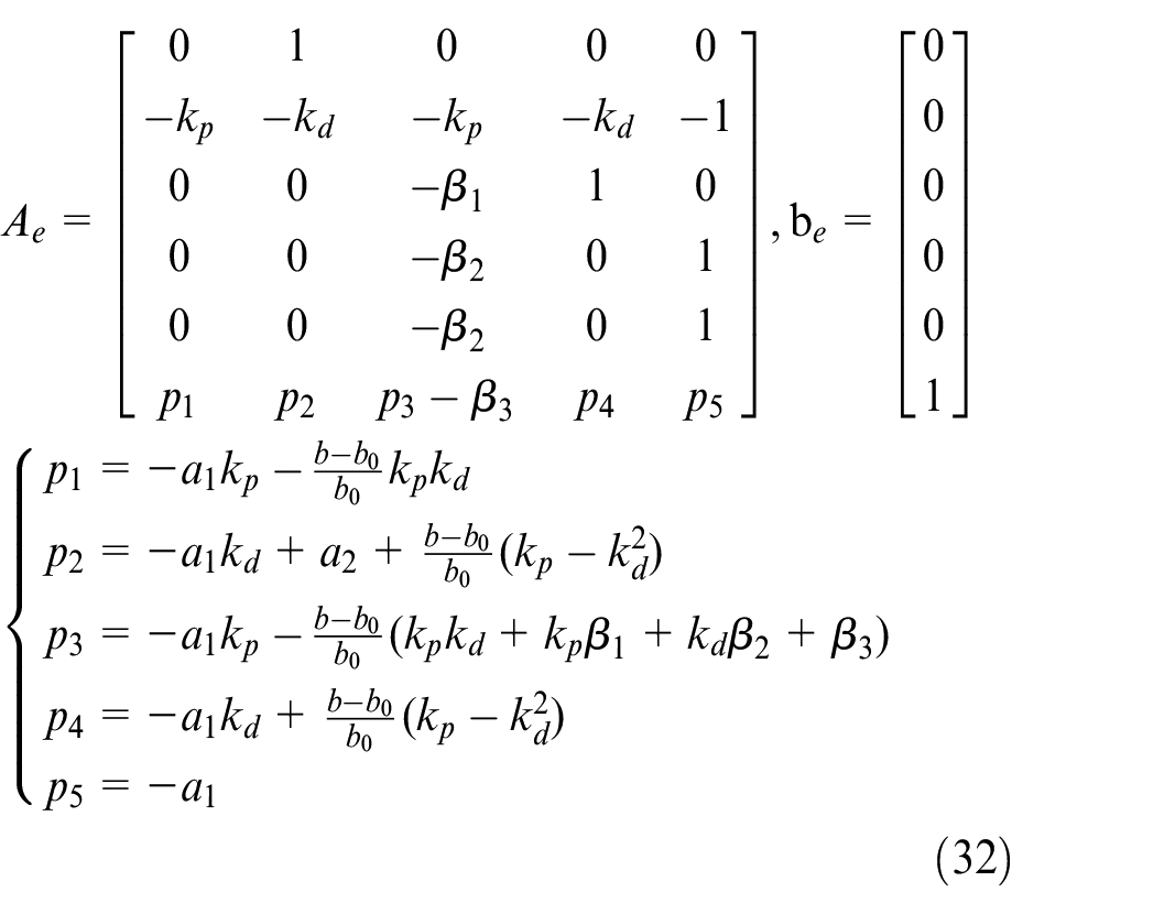
Take the state variable
According to equation (10), the transfer function of the controlled object of the system is known. where
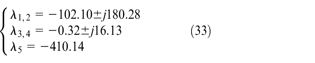
All eigenvalues of the system matrix have negative real parts, and the system is large-scale asymptotically stable according to Liapunov’s first method.
Simulation results
In this section, we designed a series of simulation algorithm programs in the simulink environment. PID, LADRC, and SMC are introduced to analyze, compare, and judge the proposed algorithms under the same conditions. Step, sine, and square wave signals are used as reference signals to test the tracking ability. To quantify the dynamic performance of the algorithms, the overshooting amount of the system response curve, the regulation time, and three error judgments are added to compare the steady-state performance of the algorithms. To compare the anti-disturbance performance of the four algorithms, an anti-disturbance test session is added to the system simulation experiment.
System tracking effect under step signal
The step signal expression is shown in equation (34):

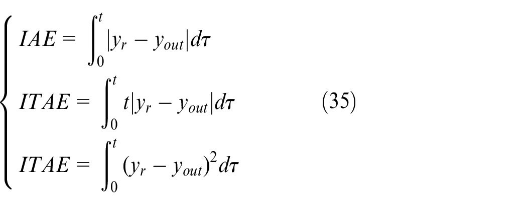
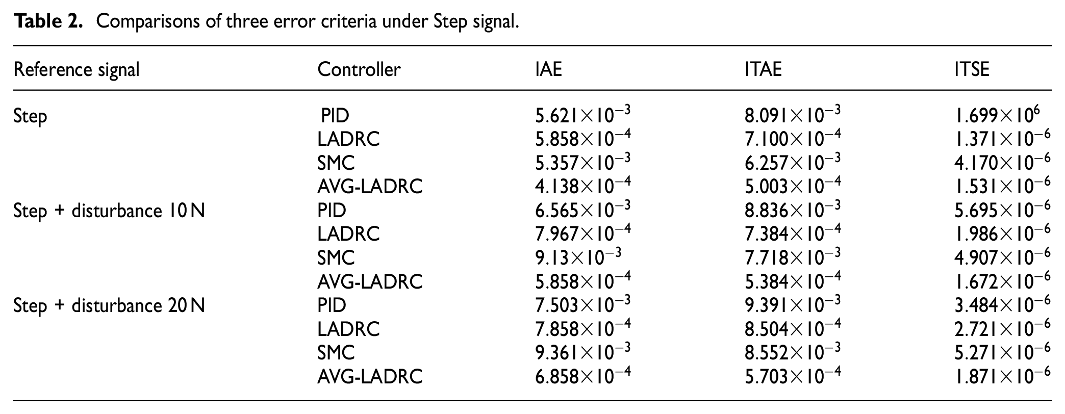
Comparison of the effects of different reference signals on the PID, LADRC, SMC, and AVG-LADRC algorithm responses. Three error criteria are introduced to quantify their response results. These three error criteria are the integral of the absolute value of error (IAE), the integral of time times the absolute value of error (ITAE), and the integral of time times squared error (ITSE). In control system design and optimization, IAE, ITAE, and ITSE are used as commonly used performance indicators. By comparing these indicators, the advantages and disadvantages of different control strategies can be comprehensively evaluated to ensure that the system achieves the best state in terms of stability, response speed, steady-state accuracy, and dynamic performance.
IAE is sensitive to error duration and provides a better evaluation of systems with large persistent deviations. For systems requiring fast response time, IAE can better reflect the error characteristics under fast response conditions. ITAE is time-weighted and is more sensitive to late errors and helps to reduce steady-state errors. ITAE reflects the effect of system regulation time and helps to optimize the regulation performance of the control system. ITSE is more sensitive to both large and late errors by weighting the error squares and time, which helps to reduce large deviations. ITSE helps to improve the smoothing performance of the system and reduce large fluctuations and has a higher evaluation value for systems requiring higher dynamic response performance. These parameters can be expressed in equation (35).
This simulation introduces a step signal, as shown in Figure 5(a) and (b). All four algorithms can realize the tracking of the signal, but their steady-state performance and dynamic effects are very different. The rise time of AVG-LADRC is 0.196 s, which is 0.248 s faster than LADRC, and the SMC is 0.677 s slower than AVG-LADRC. Even though the rise time of PID is the shortest of them all, it can bring about excessive overshooting. In contrast, the AVG-LADRC has an overshoot of only 1%, which is within the system’s allowable margin of error. As shown in Table 2. The IAE of the LADRC is 29.31% higher than that of the AVG-LADRC and 92.26% higher than that of the SMC, whereas the ITSE of the AVG-LADRC presents a smaller error value of 50.22% lower than that of the PID.To test the anti-interference capability of the system, a disturbance amount of 10N and 20N was added at two simulation times of 2 s, respectively. As shown in Figure 5(c) and (d), under the disturbance, the PID exhibits the weakness of being very sensitive to the perturbation signal, and the system shows a large variation of response values with obvious jitter. Especially, when adding a 20 N disturbance amount, the system fluctuates considerably within a certain range.
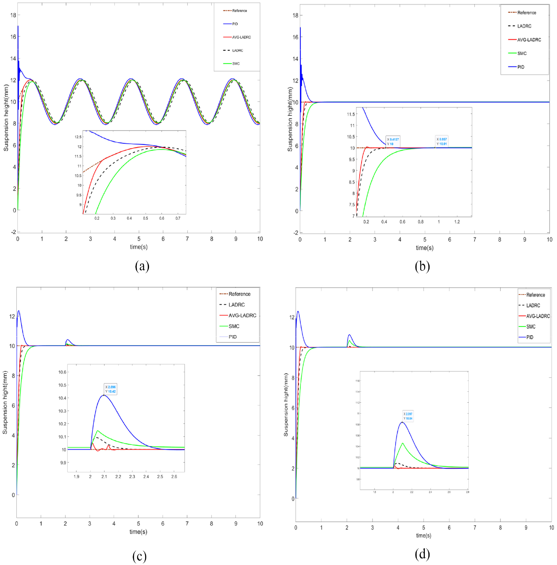
System tracking effect under step sign: (a) System tracking effect under step signal 1, (b) System tracking effect under step signal 2, (c) System tracking effect under step signal with disturbance 10N, and (d) System tracking effect under step signal with disturbance 20N.
Comparisons of three error criteria under Step signal.
The fluctuation was 0.84 mm without the addition of the perturbation and 0.42 mm with the addition of the 10N perturbation. The fluctuation amount of LADRC is 0.15 mm, followed by SMC is 0.31 mm. In comparison, AVG-LADRC’s anti-interference is superior to the comparison algorithm. Under the same interference, the AVG-LADRC has only small fluctuations, but it can return to a stable state in a short time.
Comparing the ITSE, when adding a disturbance amount of 10N, the ITSE of LADRC improves by 30.97% and the SMC improves by 15.02% compared to that of the undisturbed one, while the AVG-LADRC only changes by 8.42%.
When adding 20 N disturbance amount, the changes of the three error values of different control algorithms are more obvious, while the error indexes of AVG-LADRC are smaller than the other three algorithms. The anti-disturbance and robustness performance of AVG-LADRC has a more obvious advantage with the three algorithms compared.
System tracking effect under sinusoidal and square wave signal
The sinusoidal signal is shown in equation (36):

To further illustrate the superiority of the proposed algorithms, our simulations yielded a sinusoidal function trend in the variation of the ball’s levitation height in the magnetically levitated ball system. When a sinusoidal signal is input as the reference signal, the tracking effects of the PID, LADRC, SMC, and AVG-LADRC are shown in Figure 6(a).
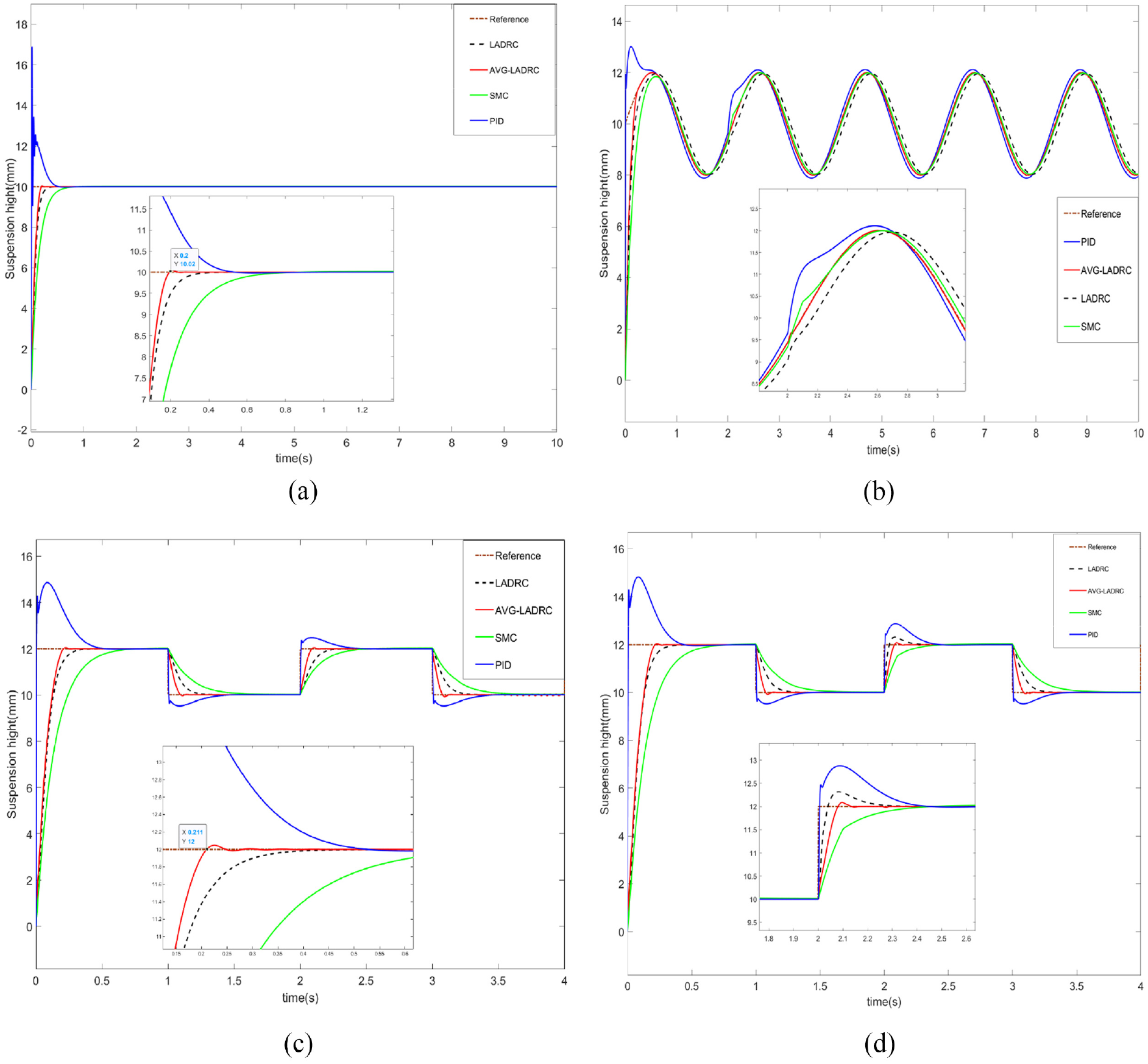
System tracking effect under step sign1: (a) System tracking effect under sinusoidal wave signal, (b) System tracking effect under sinusoidal with disturbance 10N, (c) System tracking effect under square wave signal, and (d) System tracking effect under square wave signal with disturbance 10N.
Although several other control algorithms can also achieve stabilization, they all have some phase lag, while AVG-LADRC can achieve low error tracking. For the PID algorithm, the system overshoot generated in the early stage is large and the phase is ahead of the given signal, while the SMC and LADRC generate a large phase lag. The AVG-LADRC under the comparison with the PID, the error of the system IAE is decreased by 78.46%, the error of the ITAE is decreased by 86.21%, and the value of the error of the ITSE is decreased by 91.15%. The IAE and ITSE errors under comparison with LADRC decreased by 11.39% and 14.06% respectively.
To test the performance of the algorithm to track sinusoidal signals and in the presence of interfering signals, an interference signal of 20N is added to the system at a simulation time of 2 s. As shown in Figure 6(b), the PID fluctuates about 0.5 mm, the SMC is 0.3 mm, the LADRC is 0.1 mm, and the AVG-LADRC has only small fluctuations and can return to stability quickly. Compared with the no interference case, in AVG-LADRC, the IAE is only improved by 6.65%, ITAE by 7.53%, and ITSE by 17.58%. The three error values of PID are 7.21%, 35.29%, and 17.31% respectively.
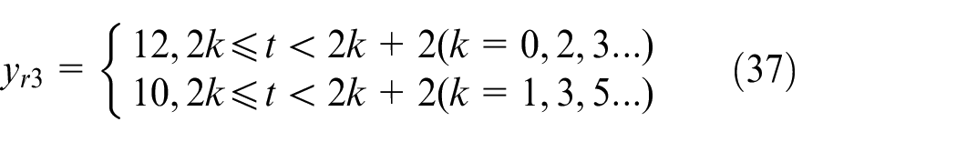
From the above analysis, it can be learned that AVG-LADRC is better than PID, LADRC, and SMC in tracking sinusoidal signals. The square wave expression is shown in equation (37).
The simulation results are shown in Figure 6(c). The simulation compares the signal tracking effect presented by the four algorithms in the paper plus in the maglev control system. The AVG-LADRC algorithm has better tracking results when compared to the other three algorithms. When the system is subjected to a sudden change in the input square wave by an external disturbance, the PID generates a larger overshoot and the stabilization time is 0.3 s longer than that of AVG-LADRC. The SMC, although the overshoot is smaller than that of the AVG-LADRC, has a long tuning time, which is longer than 0.6 s.
As shown in Table 3 and Figure 6(d) under the same disturbed signal, compared to when there is no disturbance, the error of IAE of SMC is improved by 24.84%, the error of ITAE is improved by 21.78%, and that of ITSE is improved by 17.40%. In LADRC, these three error values are improved by 40.14%, 37.81%, and 27.01%, respectively, compared to AVG-LADRC which has the smallest three error values among the four algorithms.
Comparison of three error criteria for sinusoidal and square wave signals.
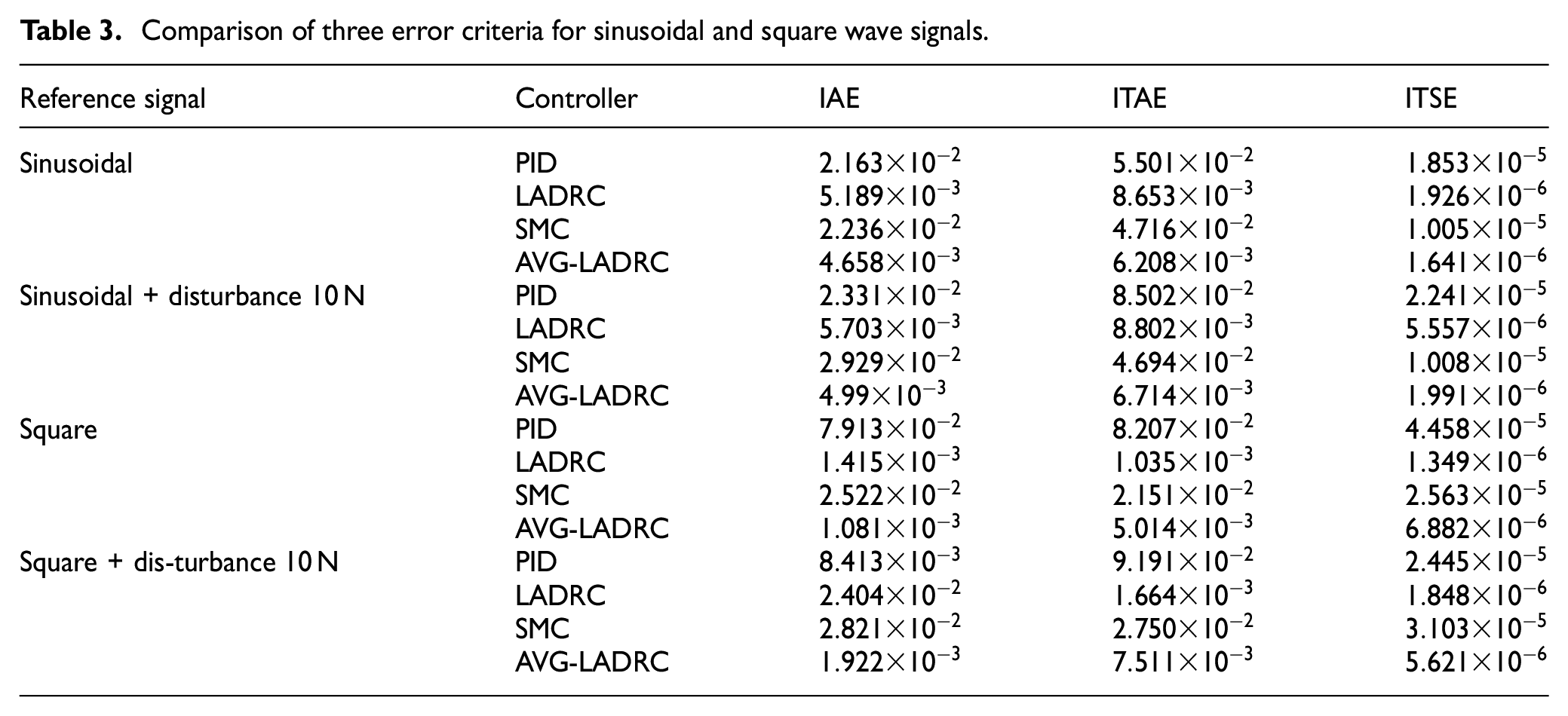
These data show that the AVG-LADRC control algorithm produces lower errors than PID, SMC, and LADRC in comparison to all three error integral judgments selected in this simulation experiment. In addition, the proposed algorithm in this thesis produces relatively better tracking results than the other algorithms. This again proves the novelty and superiority of the proposed algorithm. The selection of the four control algorithms AVG-LADRC, LADRC, SMC, and PID in the thesis is based on the wide range of applications of these methods within the control field and their respective unique advantages. Comparing these four control strategies allows for a more comprehensive evaluation of the following performance metrics of the Maglev ball control system.
(1) Robustness: the stability and reliability of each control strategy in the face of parameter variations and external perturbations of the maglev ball control system.
(2) Speed of response and overshoot: the speed of response of the system to changes in the input and the degree of overshoot before reaching a steady state.
(3) Steady-state error: the accuracy of the performance of a magnetically levitated ball system after it has reached equilibrium.
(4) Computational and implementation complexity: the computational resources and complexity required to implement each control strategy.
The choice of comparing the four control methods is reasonable. Such a comparison can provide a comprehensive assessment of the performance of each control strategy in different situations and provide theoretical and data support for the application scenarios of real magnetic levitation control algorithms.
Experimental verification
For a more in-depth validation of the effects produced by the algorithm proposed in this thesis, we verified the experimental results of the algorithm on the GML2001 experimental platform, as shown in Figure 7. The dynamic and steady state performance of the algorithm proposed in this paper is experimentally verified with three different standard signals as reference signals. This experiment uses a one-way pull-up magnetic levitation system, where the movement of the levitated ball itself is limited by longitudinal suction. The system can only control the up and down displacement of the steel ball. The structural composition of the system model contains the following key modules: measurement module, control module, and drive module.
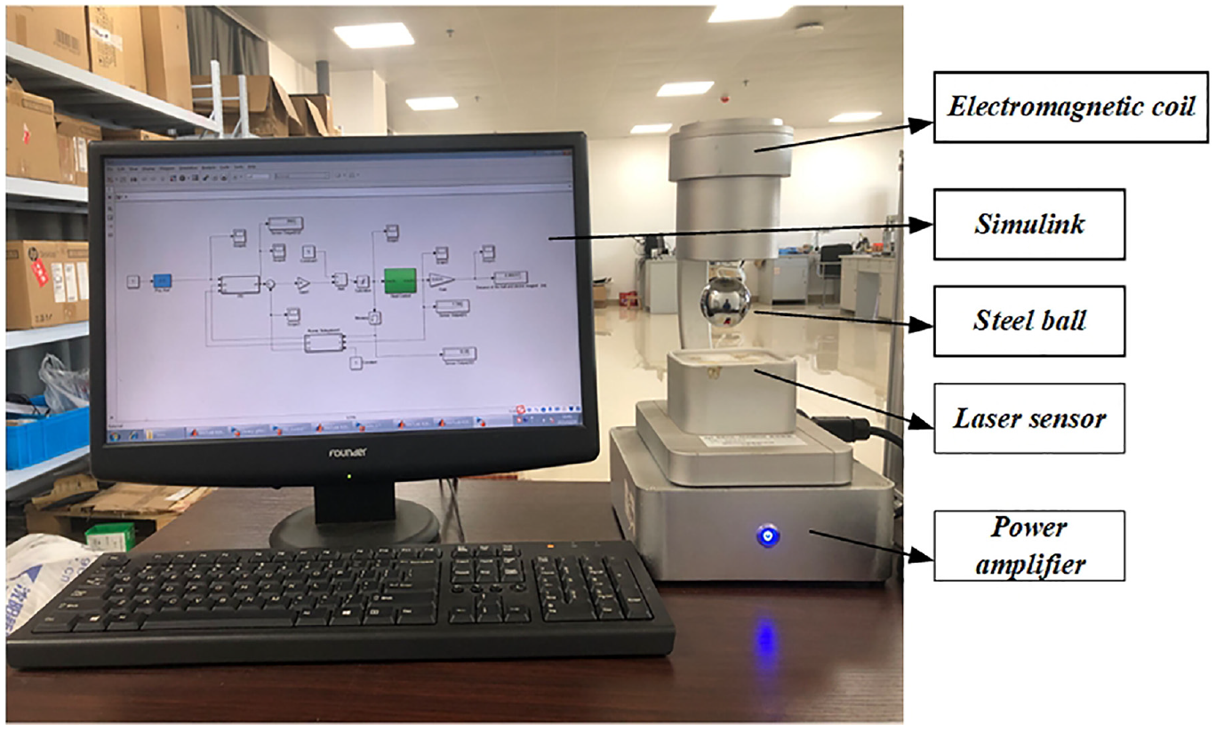
GML2001 magnetic levitation experiment platform.
The working principle of the experimental platform and the realization process of the algorithm are briefly described below. The infrared laser displacement sensor converts the reflected light signal into an electrical signal, which is processed by the computer and transformed into the real-time position signal of the ball. The signal is fed back to the controller to adjust the size of the output current, maintain the balance of the longitudinal force, and realize the stable levitation of the ball. The algorithm proposed in the paper first builds a simulation program in simulink to verify the feasibility of the algorithm.
Combined with the physical object, the experimental program is built in GML2001, and the parameters are partially adjusted according to the real-time curve to achieve a better levitation effect.
The control module contains preset control laws that output control commands based on the position information of the steel ball. The drive module is essentially a power amplifier that regulates the excitation current of the electromagnetic coil under control commands output from the controller. When the electromagnetic force generated is exactly balanced with the gravity of the steel ball, stable levitation of the steel ball with one degree of freedom can be realized.
Fixed-point suspension experiment
In this experiment, a step signal is introduced as a reference signal for the standard input as shown in equation (38). The stability of the magnetically levitated ball at a stable levitation point was verified under PID, SMC, and AVG-LADRC control algorithms, respectively.

As shown in Figure 8, the system realizes the tracking of the step reference signal. There are some errors between the desired height value and the actual output value, these errors fluctuate within 0.5 mm, and the size of the error fluctuation value is within the allowable error size of the system. After a fluctuation occurs, the ball quickly achieves dynamic equilibrium under the action of algorithm-controlled electromagnetic suction. Under experimental comparison with PID and SMC algorithms, AVG-LADRC produces smaller fluctuations and better stability than the comparative algorithms when performing experiments with fixed-point levitation of small balls.
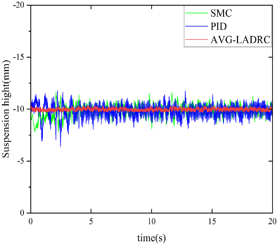
Magnetic levitation ball tracking effect under step signal.
Follow-up experiment
The tracking ability of AVG-LADRC for sinusoidal signals is first verified, and the expression for the sinusoidal signal is shown in equation (39).

As shown in Figure 9, based on the results obtained from the experiment, it can be shown that the sphere can realize the tracking of the reference signal without phase difference, and the system returns to the normal tracking curve very quickly although overshooting occurs locally. It can be seen that the maximum error occurs within a range of 2 mm, which has a minimal impact on the overall stability of the system. Under the control of the AVG-LADRC algorithm, the system can track stably for sinusoidal signals used as standard reference signals. In the real situation, some environmental disturbances are unavoidable. AVG-LADRC itself has a strong anti-disturbance performance and can realize the tracking of sinusoidal signals very well.
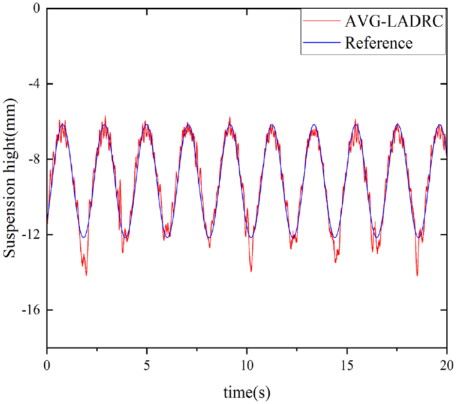
Magnetic levitation ball tracking effect under sinusoidal wave signal.
To verify the tracking ability of AVG-LADRC for square wave signals, the expression of the square wave signal used is shown in equation (40).
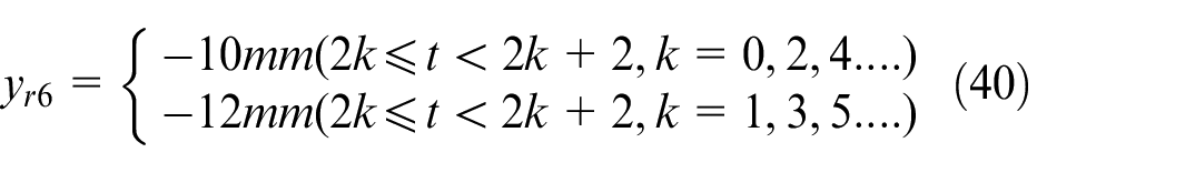
The tracking effect of the magnetically levitated ball system under the square wave signal is shown in Figure 10. The magnetically levitated ball moves according to the square wave trajectory, realizing low error tracking of the target signal. Although the magnetically levitated ball produces slight fluctuations during the experiment, it can return to the position of the reference signal very quickly. The levitation error generated by the system during the experiment is within 1 mm, the levitation error is within the allowable error accuracy, and the magnetically levitated ball presents dynamic balance stability. Under the square wave signal, the AVG-LADRC control algorithm can be better realized by the magnetic county floating blob to track the signal.

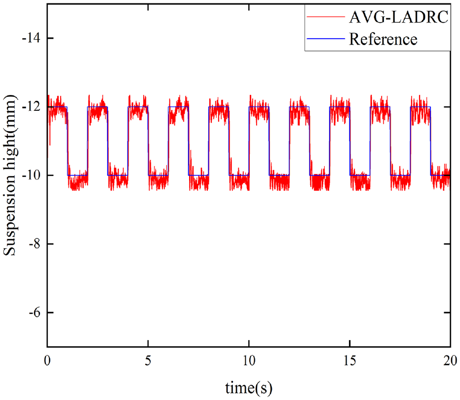
Magnetic levitation ball tracking effect under square wave signal.
The tracking effect of the magnetically levitated ball system under the sawtooth wave signal is shown in Figure 11. The magnetic levitation ball moves according to the sawtooth wave trajectory and realizes the low error tracking of the target signal. The magnetic levitation ball is dynamically balanced and stable, and the levitation error generated by the system during the experiment is within the allowable error range of the system.
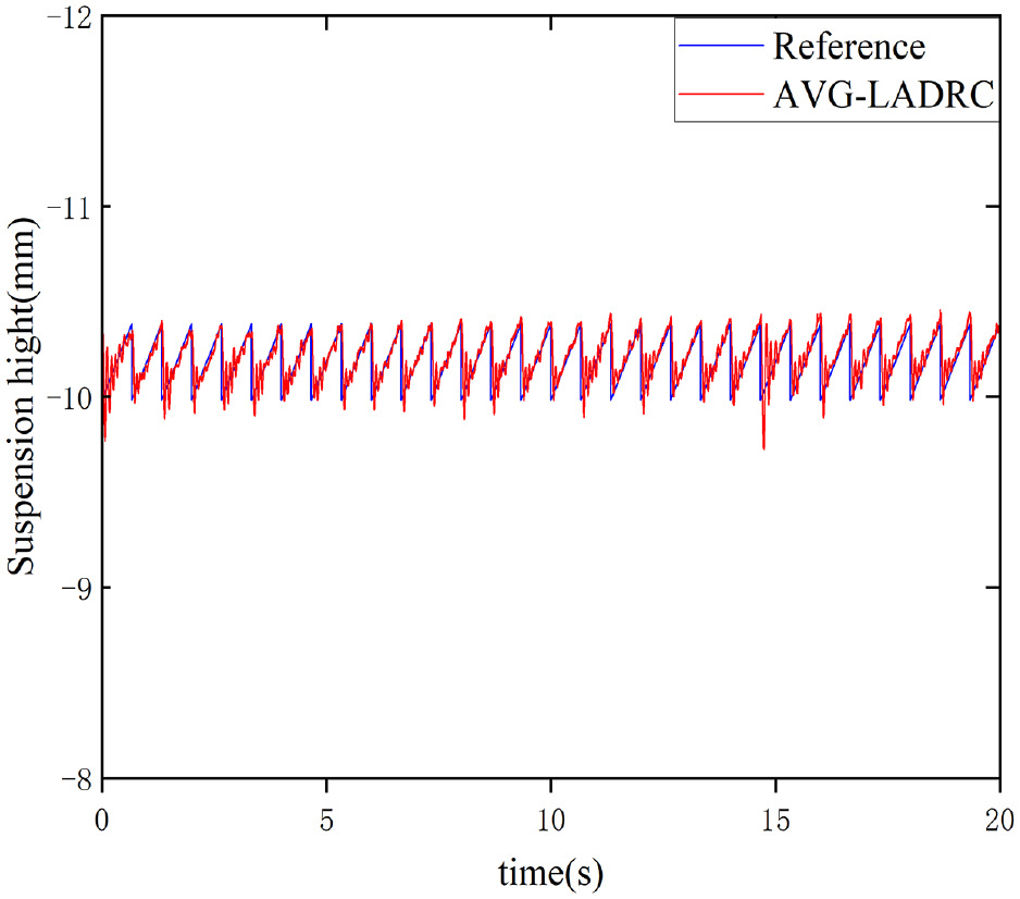
Magnetic levitation ball tracking effect under sawtooth wave signal.
Analysis of experimental results
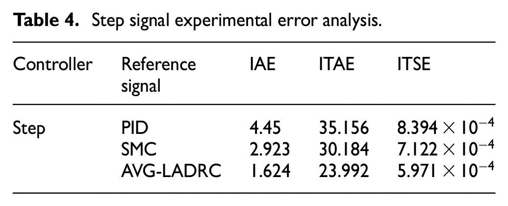
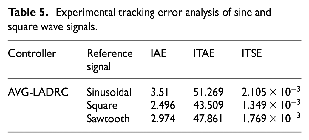
To describe the experimental results more accurately, we calculated three error coefficients in the experiments of fixed-point levitation of a magnetically levitated ball and the tracking of sinusoidal, square, and sawtooth wave signals. The definitions of IAE, ITAE, and ITSE have been defined in equation (35). The experimental data show that as shown in Tables 4 and 5. The AVG-LADRC algorithm proposed in this paper reduces 46.53% and 40.58% in ITAE and ITSE, respectively, compared to PID when the step signal is used as the reference signal. These values are reduced by 25.81% and 19.2% compared to SMC, in addition to a 79.98% reduction in IAE. The AVG-LADRC algorithm can achieve stable tracking during tracking experiments with three different reference signals, which once again proves the reliability of the AVG-LADRC algorithm.
Step signal experimental error analysis.
Experimental tracking error analysis of sine and square wave signals.
Conclusions
In the research of this thesis, we have proposed the AVG-LADRC algorithm for stabilizing the levitation of a magnetically levitated ball system. Firstly, the adaptive iterative algorithm is introduced to be combined with LADRC, which solves the problem that the bandwidth of LESO in LADRC is difficult to rectify. Secondly, to solve the problem that the parameters
To prove the superiority of the proposed algorithms, three model-independent algorithms, namely, PID, SMC, and LADRC, are introduced and used as comparison algorithms. In this thesis, rigorous simulations and experiments are conducted to compare and analyze the effectiveness of the AVG-LADRC algorithm in depth in terms of the evaluation metrics of dynamic and steady-state performance. The tracking performance of the algorithm is verified by using a step signal, a sine signal, and a square wave signal as reference signals, respectively. The immunity of the proposed algorithm is also verified by introducing the same amount of interference in the same environment. After extensive simulation and experimental validation, the results obtained show that AVG-LADRC has better accuracy, speed, and anti-interference performance compared with PID, SMC, and LADRC.
Future research work will focus on the further adaptive optimization of parameters
Footnotes
Declaration of conflicting interests
The author(s) declared no potential conflicts of interest with respect to the research, authorship, and/or publication of this article.
Funding
The author(s) disclosed receipt of the following financial support for the research, authorship, and/or publication of this article: This work was supported in part by the Key Project of Natural Science Foundation of Jiangxi Provincial Science and Technology Department under Grant 20232ACB202001; in part by the National 14th Five-Year Plan for Key Research and Development under Grant 2023YFB4302100; in part by the Major Special Project of Jiangxi Provincial Science and Technology Department under Grant 20232ACE01011; in part by the Program of Qingjiang Excellent Young Talents in Jiangxi University of Science and Technology under Grant JXUSTQJBJ2019004; in part by the Research Projects of Ganjiang Innovation Academy, Chinese Academy of Sciences. (No.E255J001).
Data availability statement
Data sharing not applicable to this article as no datasets were generated or analyzed during the current study