
Abstract
This paper introduces a novel control method to address lateral stability challenge in distributed driving electric vehicles. By considering inherent time delay and unknown sensor measurement error generated from design, manufacturing, and external disturbances, the proposed approach achieves better robustness. Firstly, we establish a two-degree-of-freedom (2-DOF) dynamic model for lateral motion of an electric vehicle driven by in-wheel motors (EV-DIM). Based on this model, a control system considering time delay and unknown sensor measurement error is constructed. The control system incorporates a controller based on a dual domination gains observer, and its global asymptotic stability is rigorously proved by the Lyapunov method. Numerical simulations and co-simulations via CarSim and Simulink verify the method’s effectiveness. Compared to the sliding mode control, the proposed method shows better performance which indicates this approach promising for enhancing lateral stability of an electric vehicle.
Keywords
Introduction
Distributed drive electric vehicles present a novel chassis structure compared to traditional counterparts, significantly simplifying the powertrain system. This advancement facilitates vehicle lightweighting and augments energy efficiency. The incorporation of multi-wheel independent drive permits individual wheel operation, while enabling coordinated control in accordance with overall vehicle requirements. This attribute holds promise for enhancing overall vehicle stability during operation. 1
When an electric vehicle is driven at high speed, sudden disturbances can induce hazardous lateral movements, challenging drivers to respond swiftly in emergencies. 2 Hence, developing lateral stability control techniques for enhancing the safety of electric vehicles is paramount.
In recent years, researchers have introduced diverse approaches to tackle lateral stability control in vehicles. For instance, Nam et al. 3 proposed a method to enhance the stability of electric vehicles by estimating the vehicle’s slip angle using tire lateral force sensors. a vehicle stability controller was formulated leveraging the LuGre tire model to achieve the specified control objectives.4,5 Zhang et al. 6 developed an optimal control approach grounded in quadratic optimal control theory to effectively mitigate yaw angle deviation of the center of gravity during cornering maneuvers. Li et al. 7 have developed a linear time-varying model predictive control (LTV-MPC) method based on a two-degree-of-freedom vehicle model.
In contrast to traditional vehicles, which require additional hydraulic control units to produce yaw moments for stabilizing vehicle motion through differential hydraulic braking, distributed drive electric vehicles can conveniently utilize motors to generate differential driving torques for stability control without compromising vehicle dynamics. Feng et al.
8
integrated the principles of active disturbance rejection control (ADRC) theory and sliding mode control to develop a novel direct yaw moment control (DYC) controller customized for 4 WID-EV. In order to enhance the longitudinal and lateral stability of vehicles under extreme conditions, Li et al.
9
introduced a real-time controller for four-wheel independent motor-driven electric vehicles based on NMPC. Jin et al.
10
employed linear parameter-varying techniques to devise a robust gain-scheduled H
Sliding mode control, as a classic control method, also enjoys extensive application in vehicle lateral stability control. Tian et al. 14 have developed an approach that integrates sliding mode control with optimal allocation algorithms, utilizing a hierarchical structure to control vehicle lateral stability. Xiao 15 partitioned the original model of the unmanned aerial vehicle into two components to accomplish trajectory planning and ensure flight stability: an attitude control model regulated by a sliding mode controller, and an altitude control model managed by an extended state observer. To represent the reference longitudinal velocity reflecting the actual speed, Chen et al. 16 employed a combination of a neural network observer and a fuzzy logic controller. They devised a novel lateral control system comprising high, medium, and low-level subsystems to ensure the smooth and safe operation of vehicles on roads with low adhesion. Wang et al. 17 utilized sliding mode control with longitudinal and lateral velocities, along with yaw angular velocity, as control variables to determine required longitudinal and lateral forces, and yaw moments. They integrated a cost function with adjustable weight coefficients to consider motor power and tire load. Ma et al. 18 implemented an integral terminal sliding mode (ITSM) controller, considering parameter uncertainties, to swiftly achieve lateral stability, while employing velocity tracking for longitudinal stability.
As neural networks advance, their utilization in enhancing lateral stability control in automotive vehicles is developing. Cao et al. 19 devised a robust steering control system utilizing BVSC to mitigate lateral path tracking deviations, counteract unknown external disturbances, and ensure the lateral stability of autonomous driving vehicles. Huang et al. 20 employed the BP-PID algorithm to devise a DDEV multi-model control system (MMCS) based on direct yaw moment control.
In real-world scenarios, disturbances affecting vehicles are often uncertain, and control systems mostly involve nonlinear terms. Hence, taking into account the time-varying nature of vehicle velocity and the uncertainty of external disturbances, Meng et al. 21 proposed a method more suitable for computer implementation, termed the Sampled-Data Output Feedback Control with Almost Disturbance Decoupling method. To address potential uncontrollability near the origin resulting from nonlinearity, Meng et al. 22 developed a homogenous control method based on sampled-data output feedback. Considering the uncertainty in vehicle longitudinal velocity and controller saturation, Li et al. 12 introduced a homogeneous polynomial parameter-correlation method to address the issue. They designed a multi-objective controller to enhance the lateral dynamic stability and maneuverability of distributed drive electric vehicles by achieving the desired external yaw moment.
The aforementioned research method does not tackle practical engineering issues such as system delays and unknown errors in sensor sensitivity. Fortunately, some researchers have explored these issues in theory. Sun et al.23,24 studied the global output feedback stabilization problem of a class of uncertain nonlinear systems. They utilized a dual control approach to address time-varying measurement errors and delayed states. This control strategy relies on the selection of Lyapunov-Krasovskii functionals and the development of novel state observers, thus eliminating the requirement for output functions and nonlinear information. Shao et al. 25 stabilized a nonlinear system by introducing the power integral method. They devised a novel continuous controller to resolve the global stabilization issue of the system.
In this paper, we investigate the lateral motion stability of an EV-DIM considering time delay and unknown sensor measurement error, and propose a vehicle stability control method based on a dual domination gains observer. The contributions of this study are as follows.
A 2-DOF dynamic model of an EV-DIM for lateral motion is constructed. This model reflects the errors between actual values and ideal values for sideslip angle and yaw velocity that provide the basis for the following controller design.
A lateral stability error tracking control system is constructed which considers the unknown sensor measurement error and time delay. The unknown sensor measurement error is caused by external disturbances, sensor design, manufacture, etc. The time delay arises due to factors such as sensor data processing, system synchronization, gaps in the mechanical system, etc.
A lateral stability controller based on dual domination gains observer is designed which has better robustness. The two domination gains are used to deal with the influences of the unknown sensor measurement error and time delay.
The rest of paper is organized as follows. Section 2 introduces the lateral motion dynamics model of EV-DI M taking into account uncertain disturbances. In Section 3, a controller and observer based on dual control gain are designed. Section 4 conducts numerical simulations of the lateral stability of an EV-DIM. Section 5 carries out co-simulations via CarSim and Simulink and makes comparisons with sliding mode control, thereby validating the effectiveness and superiority of the proposed method.
The lateral motion dynamic model of EV
In order to simplify the lateral stability control method for four-wheel-drive electric wheel vehicles, this paper reduces the four-wheel-drive electric wheel vehicle to a 2-DOF single-track model as shown in Figure 1.
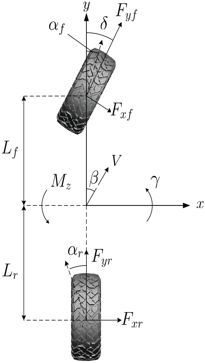
The two-degree-of-freedom model of an electric vehicle driven by in-wheel motors.
Although this model is similar with the fuel vehicle model, the key distinction lies in the fact that each wheel is individually powered by a hub motor, which is different from the fuel automotive structure. Due to the hub motor’s rapid and precise torque response, it is easy to generate an additional torque
where
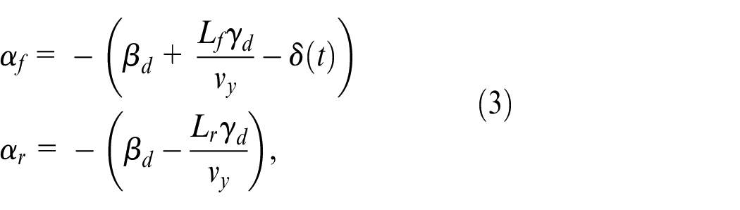
The lateral forces of the front and rear tires can be calculated using the following linear tire model. 26

where
where
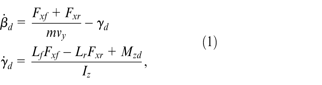
In practical operating conditions, electric vehicles suffer various external disturbances while driving within their lanes. These disturbances can significantly impact the vehicle’s behavior and performance. Consequently, the actual 2-DOF electric vehicle model can be succinctly expressed as
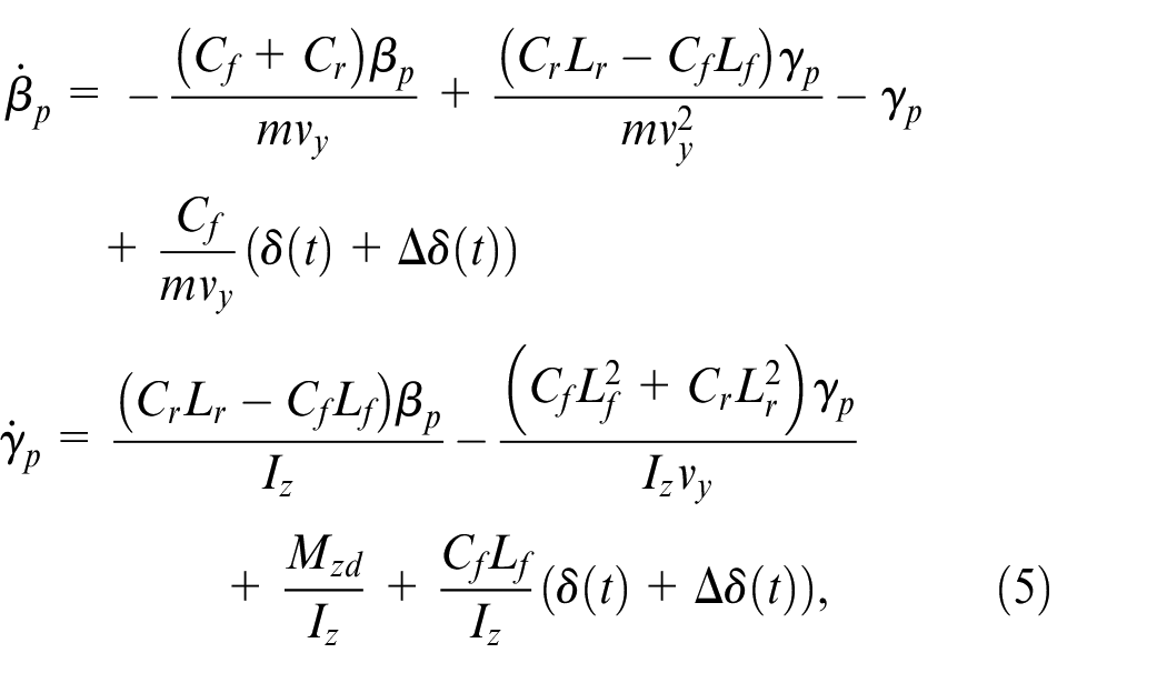
where
Despite

where
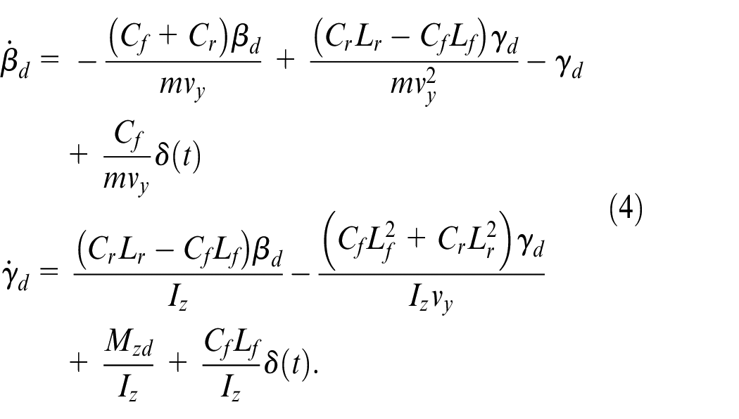
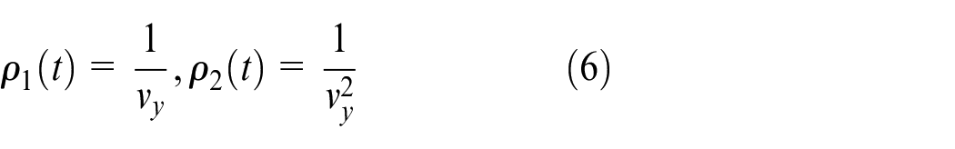
Furthermore, to accurately reflect practical conditions, this study also takes into account the presence of unknown sensor measurement errors and time delay. As a result, we introduce the variable
Based on equations (4) and (5), one can obtain
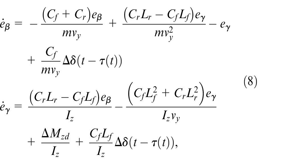
where
Let

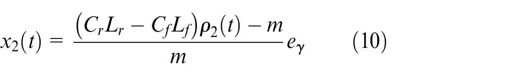

system (8) can be rewritten as
where
Lateral motion stability control method based on dual domination gains observer (DDGO)
The aim of this paper is to develop a lateral stability controller for electric vehicles, which tackles challenges associated with unknown sensor measurement error and system time delays. We describe this achievement by Theorem 1.
where
Design of linear observer
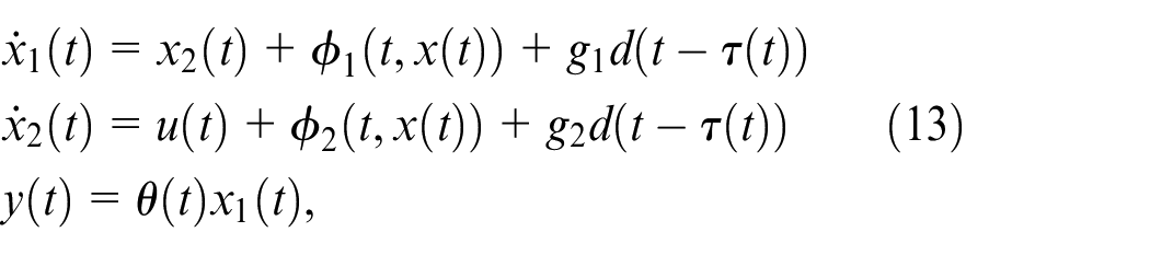
In system (13),
where
Then

where

where
Construct a positive definite matrix
Under Assumption 2, the derivative of
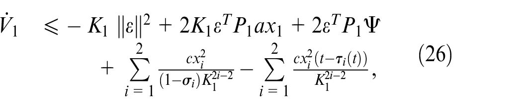
where
By Lemma 1, we deduce the following inequality from (26).
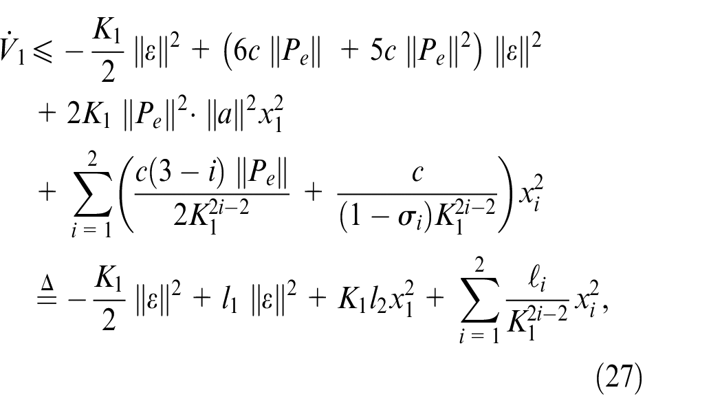
where
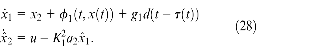
Design of output feedback control law
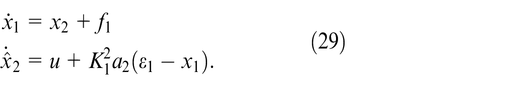
According to equations (13) and (21), there exists
We denote
The coordinate transformation for system (29) is
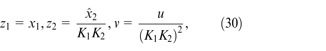
where
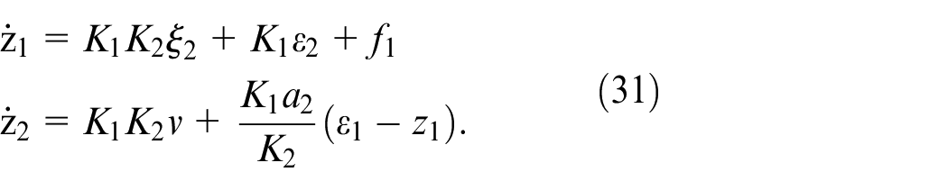
Therefore, we design an output feedback controller for system (30) as

where the positive constants
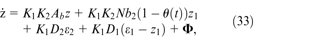
where
Similar to the information provided above,
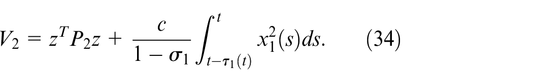
With Assumption 2, the derivative of
By Lemma 1, we deduce the following inequality from (35)
where
According to Lemma 2, we select
Then (26) can be rewritten as
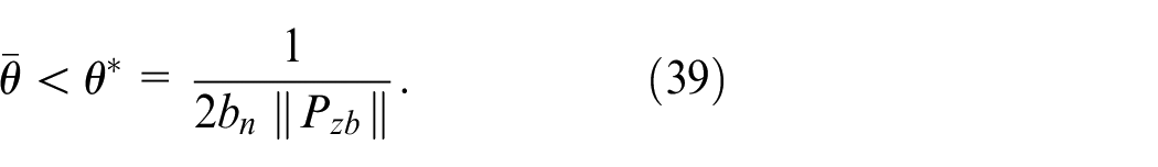
Next, we define the upper limit for the allowable sensor measurement error as
According to Lemma 1, it is easy to obtain
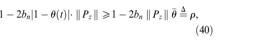
where
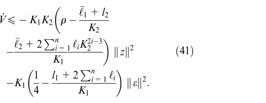
We choose the two domination gains
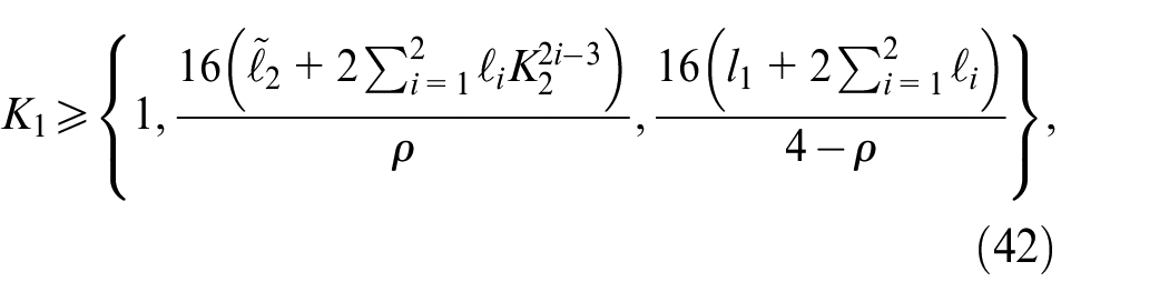
Then (41) can be rewritten as
It is obvious that equation (44) is negative definite. Therefore, we have proven that by choosing appropriate domination gains
The following notations will be used in the analysis. For a real vector
Based on the existence and continuity of solutions, the closed-loop system state composed of
(i) The bound of
where
where
where

For any
Based on the aforementioned inequalities,
(ii) The proof of
(iii)
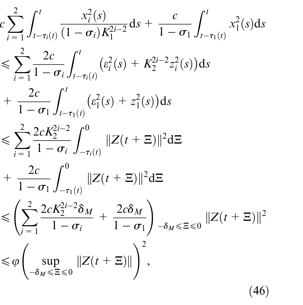
On the other hand, the boundedness of
According to equation (30), it is evident that
Therefore, the closed-loop system composed of (13), (29), (30), and (32) is uniformly asymptotically stable.
Numerical simulation
To assess the control effectiveness of the designed controller for vehicle stability, we employed a sliding mode controller for comparison. Numerical simulations were conducted using a MATLAB/Simulink numerical solver model. Simulations were carried out at vehicle speeds of 60, 80, and 120 km/h.
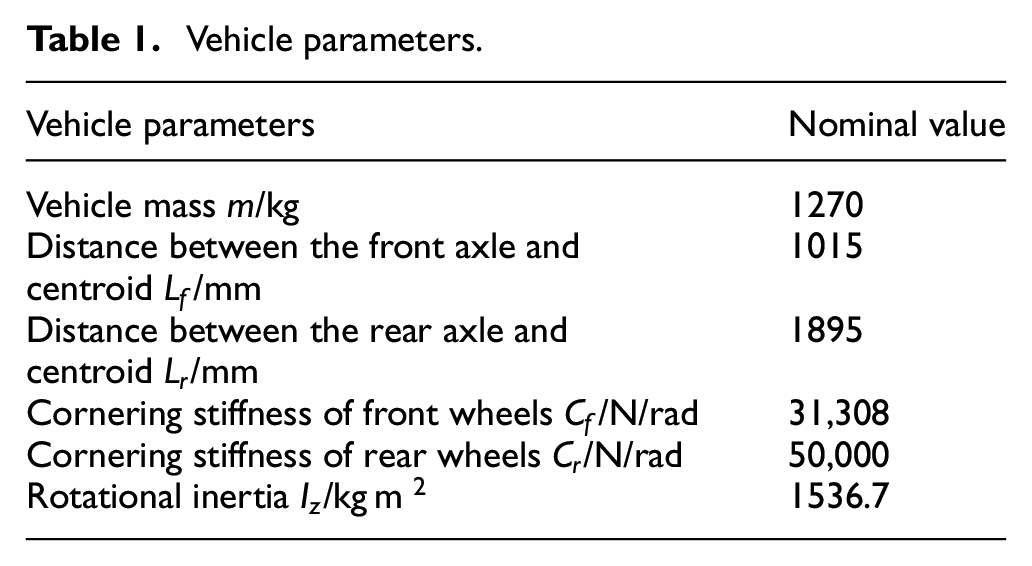
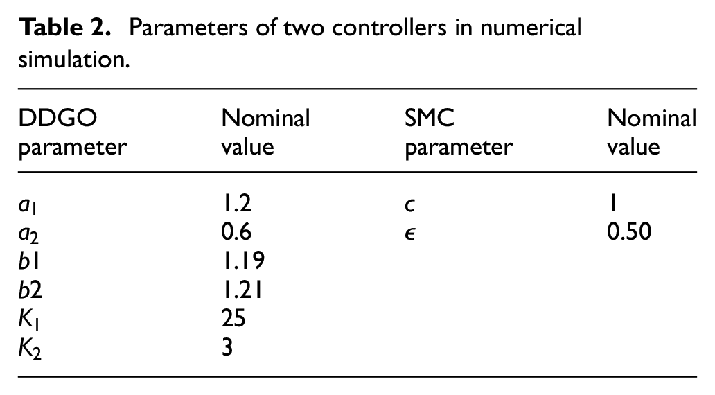
Table 1 provides the vehicle parameters utilized in this numerical simulation, while Table 2 provides the controller parameters.
Vehicle parameters.
Parameters of two controllers in numerical simulation.
Numerical simulation at 60 km/h
At a speed of 60 km/h, the yaw velocity using the designed DDGO controller and the sliding mode controller is depicted in Figure 2. From the figure, it is evident that under the DDGO controller, the maximum oscillation value is approximately 0.27 rad/s. After 1.45 s, the oscillation value at the peak is approximately 0.22 rad/s. And it is stabilized to zero after 3.356 s. In contrast, when employing the sliding mode controller, the maximum oscillation value of the lateral angular velocity reaches as high as 0.44 rad/s. After 1.627 s, the oscillation value at the peak remains at 0.253 rad/s. Subsequently, it is stabilized to zero after 3.593 s.
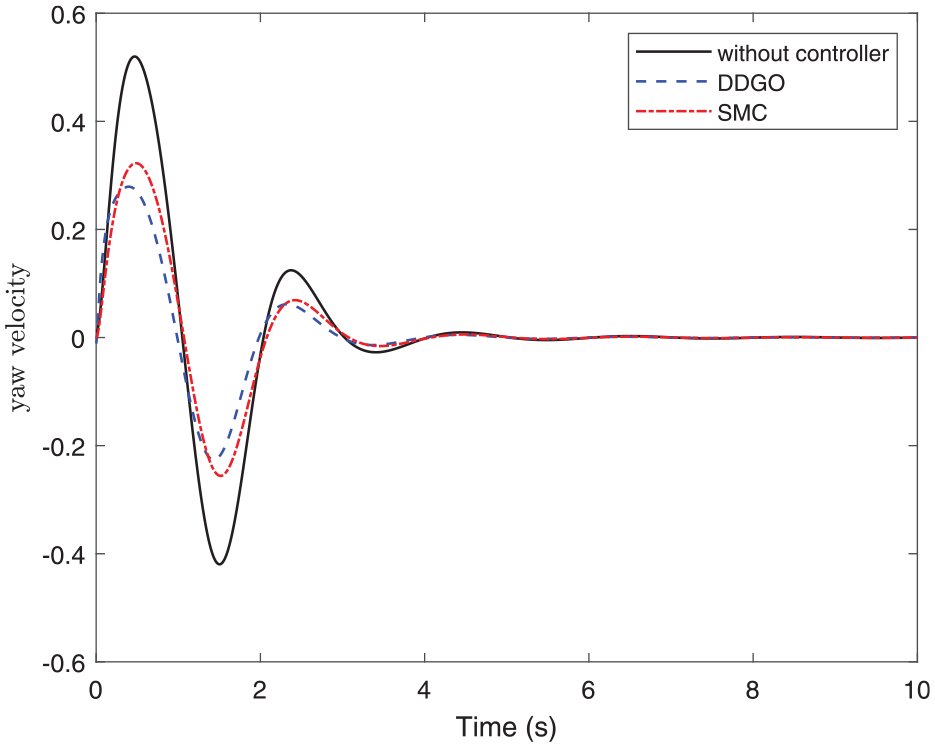
The yaw velocity with DDGO controller and sliding mode controller at 60 km/h of numerical simulation.
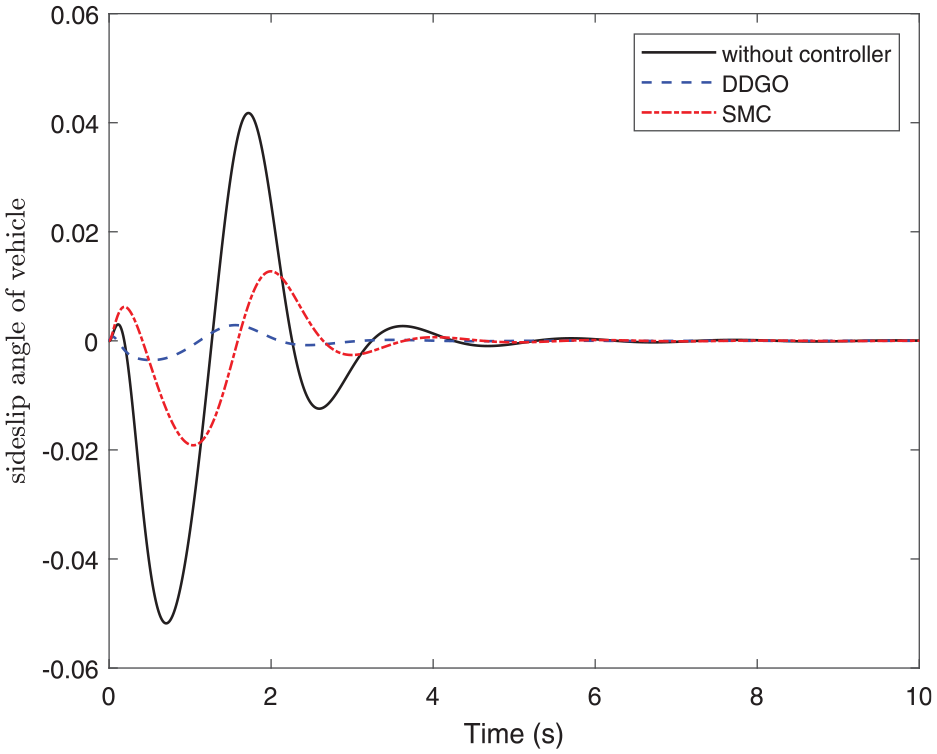
As depicted in Figure 3, with the DDGO controller, the maximum oscillation value of the side slip angle is 0.0032 rad/s. After 1.576 s, the oscillation value at the peak is 0.0026 rad/s. Followed by rapid attenuating, it reaches zero after 3.351 s. In contrast, when employing the sliding mode controller, the maximum oscillation value of the side slip angle is about 0.0138 rad/s. After 1.2 s, the oscillation value at the peak is about 0.0077 rad/s. Subsequently, it is stabilized to zero after 5.096 s.
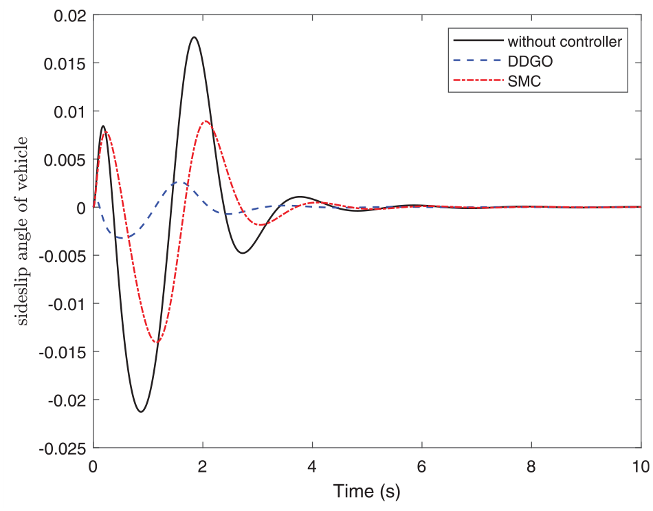
The sideslip angle with the DDGO controller and sliding mode controller at 60 km/h of numerical simulation.
Numerical simulation at 80 km/h
Figure 4 illustrates the velocity with the DDGO controller at 80 km/h, where the maximum oscillation value is 0.26 rad/s. After 1.363 s, the yaw velocity stabilizes near zero. In contrast, the sliding mode controller exhibits a higher maximum oscillation value of approximately 0.205 rad/s. It takes 4.1 s for the oscillations to converge to zero. As shown in Figure 5, under the DDGO controller, the maximum oscillation value of the side slip angle is only 0.0027 rad. Subsequently, the slip angle rapidly approaches zero after 3 s. The sliding mode controller, on the other hand, reaches an oscillation peak of 0.0188 rad. After several oscillation peaks, the side slip angle also tends toward zero after 4 s.
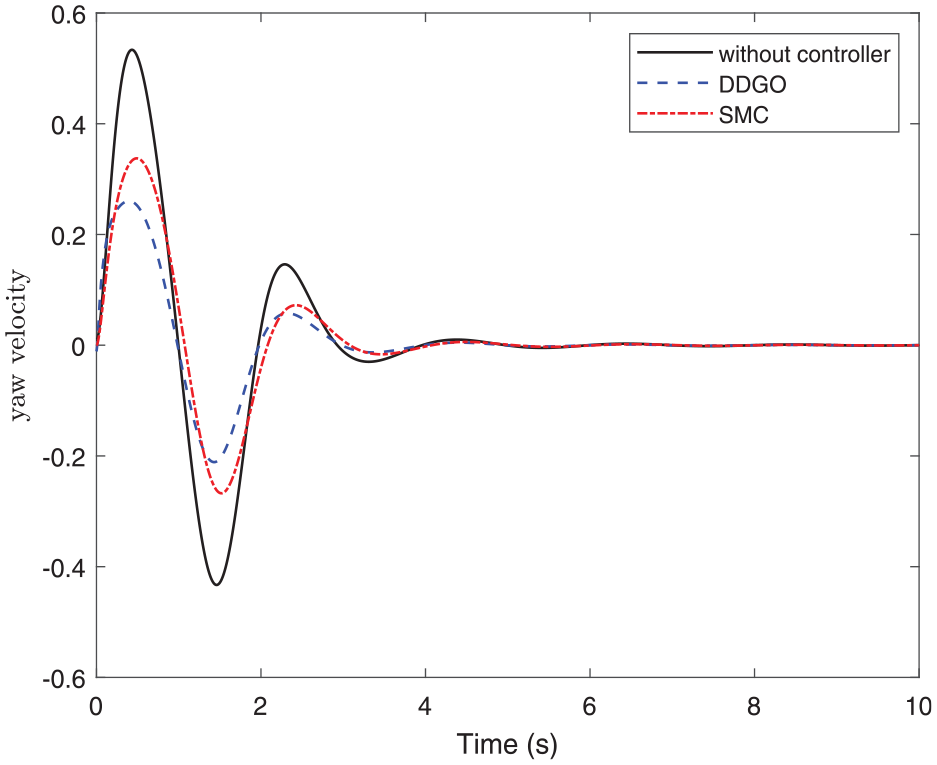
The yaw velocity with the DDGO controller and sliding mode controller at 80 km/h of numerical simulation.
The sideslip angle with the DDGO controller and sliding mode controller at 80 km/h of numerical simulation.
Numerical simulation at 120 km/h
Figure 6 illustrates the yaw velocity with the DDGO controller at 120 km/h, where the maximum oscillation value is 0.18 rad/s. After 4.012 s, the yaw velocity is stabilized to zero. In contrast, the sliding mode controller exhibits a higher maximum oscillation value of approximately 0.413 rad/s. It takes 4.1 s for the oscillations to converge to zero. As shown in Figure 7, under the DDGO controller, the maximum oscillation value of the side slip angle is only 0.0042 rad. Subsequently, the side slip angle rapidly approaches zero after 2.8 s. The sliding mode controller, on the other hand, reaches an oscillation peak of 0.067 rad. After several oscillation peaks, the lateral yaw angle also tends toward zero after 4.5 s.
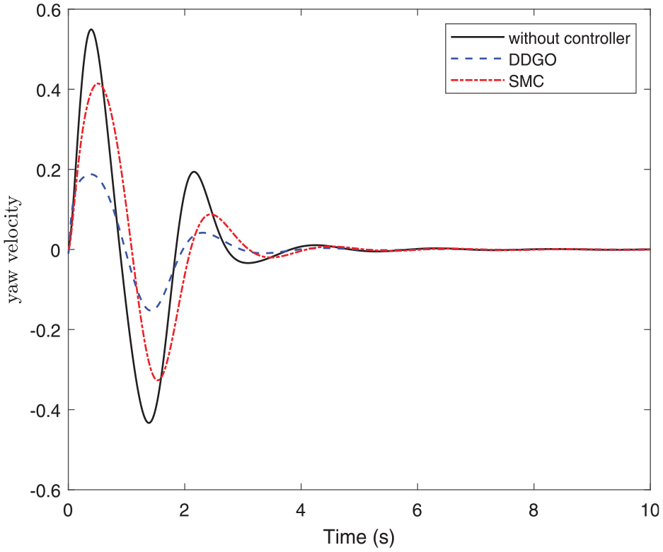
The yaw velocity with DDGO controller and sliding mode controller at 120 km/h of numerical simulation.
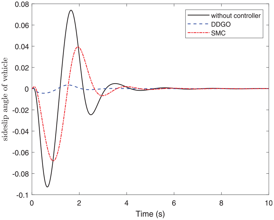
The sideslip angle with the DDGO controller and sliding mode controller at 120 km/h of numerical simulation.
Simulation results indicate that the DDGO controller demonstrates superior control performance in terms of yaw velocity and sideslip angle compared with the sliding mode controller. And the DDGO controller exhibits robustness, rendering it more suitable for lateral stability control system.
Co-simulation analysis
In the previous section, we conducted simulations and comparisons of control laws based on 2-DOF model by Matlab software. The results affirm the viability of the proposed method. However, it is important to note that an automobile is complex comprised of numerous components. For further verifying the effectiveness of the proposed method in engineering, we will employ CarSim, a specialized software for automotive dynamics simulation, in conjunction with Simulink within the Matlab environment, to conduct comprehensive analysis of the system’s performance in this section. The simulated vehicle’s speeds are set at 80 and 120 km/h, respectively, while the road’s surface exhibits a coefficient of friction of 0.85.
Analysis of double lane-change test
This test is typically used to assess the stability and handling of a vehicle during rapid, consecutive lane changes. In the simulation, the vehicle is required to quickly switch from one lane to another and then back to the original lane at a certain speed. The objective of this test is to observe the vehicle’s response to such abrupt maneuvers, including body roll, yaw response, and the time required to regain stability. The specific input parameters of the double lane-change of CarSim software are shown in Figure 8.
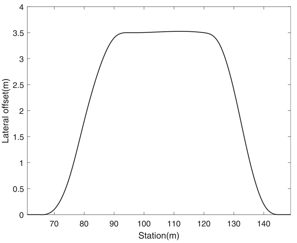
Double lane change input settings in CarSim.
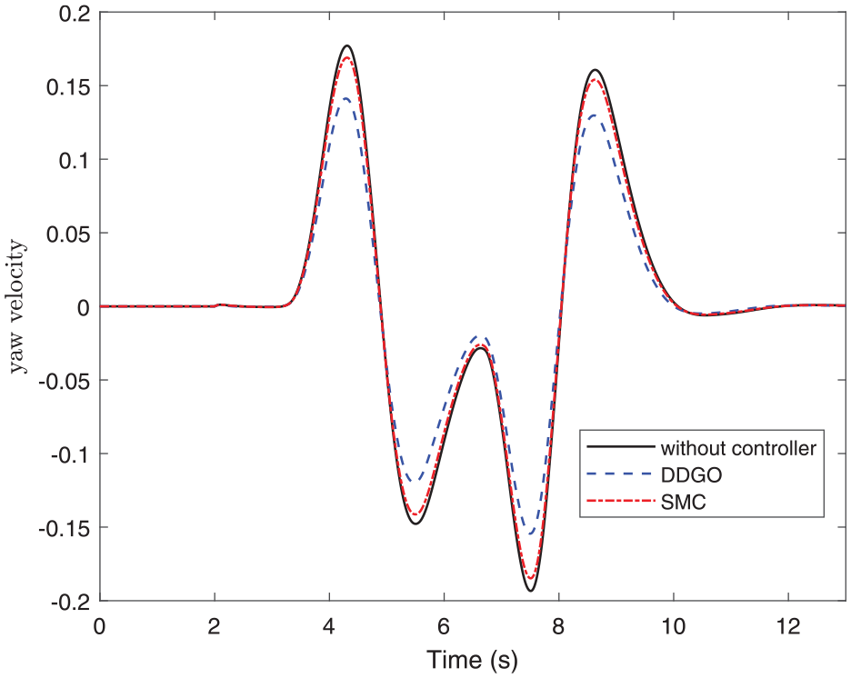
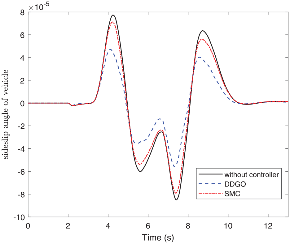
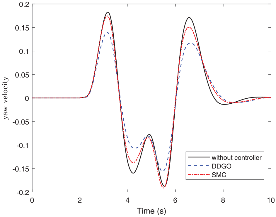
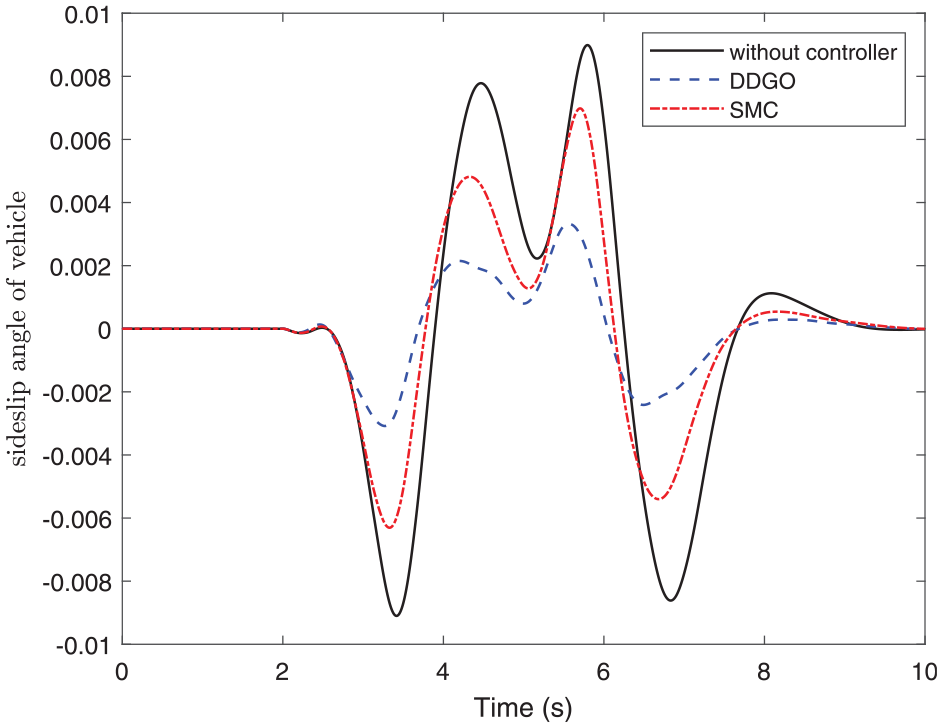
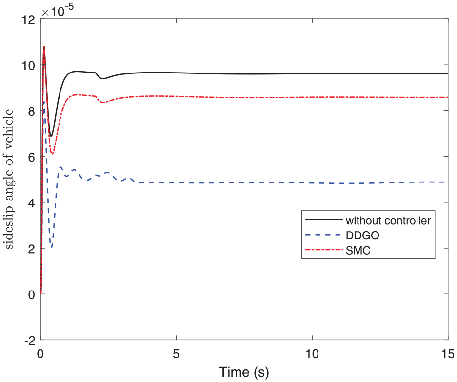
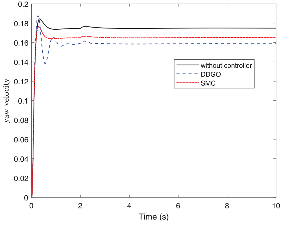
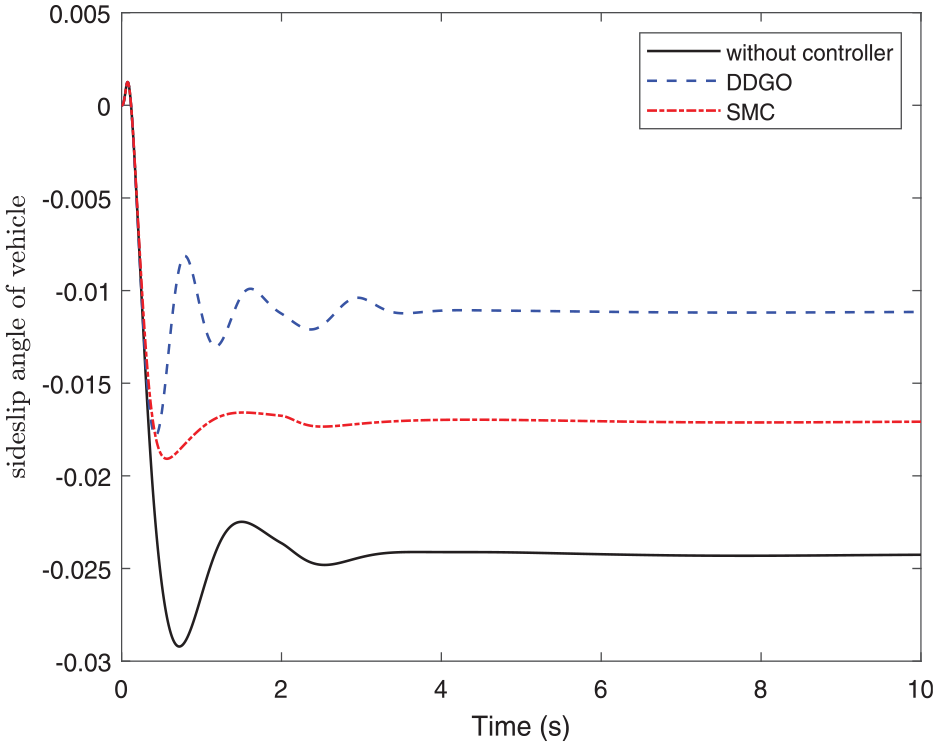
In Figures 9 to 14, it is evident that the DDGO controller shows markedly superior attenuation effects compared to the SMC method. The fluctuation of control parameters is comparatively smoother, indicating better resistance to disturbance.
The yaw velocity with the DDGO controller and sliding mode controller at 60 km/h of co-simulation for double lane-change.
The sideslip angle with the DDGO controller and sliding mode controller at 60 km/h of co-simulation for double lane-change.
The yaw velocity with the DDGO controller and sliding mode controller at 80 km/h of co-simulation for double lane-change.
The sideslip angle with the DDGO controller and sliding mode controller at 80 km/h of co-simulation for double lane-change.
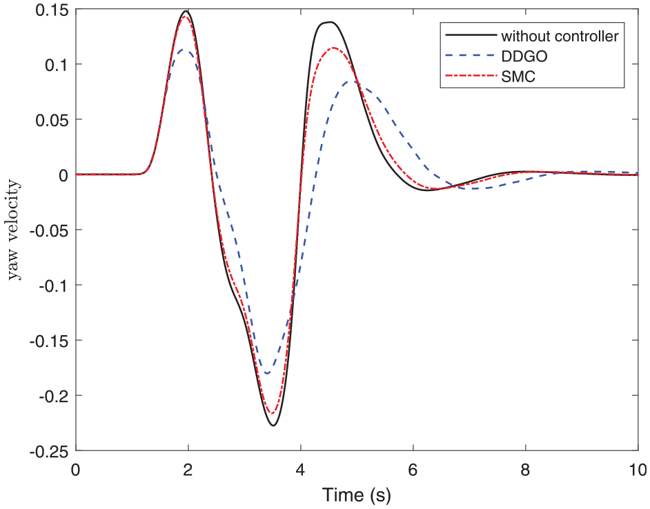
The yaw velocity with DDGO controller and sliding mode controller at 120 km/h of co-simulation for double lane-change.
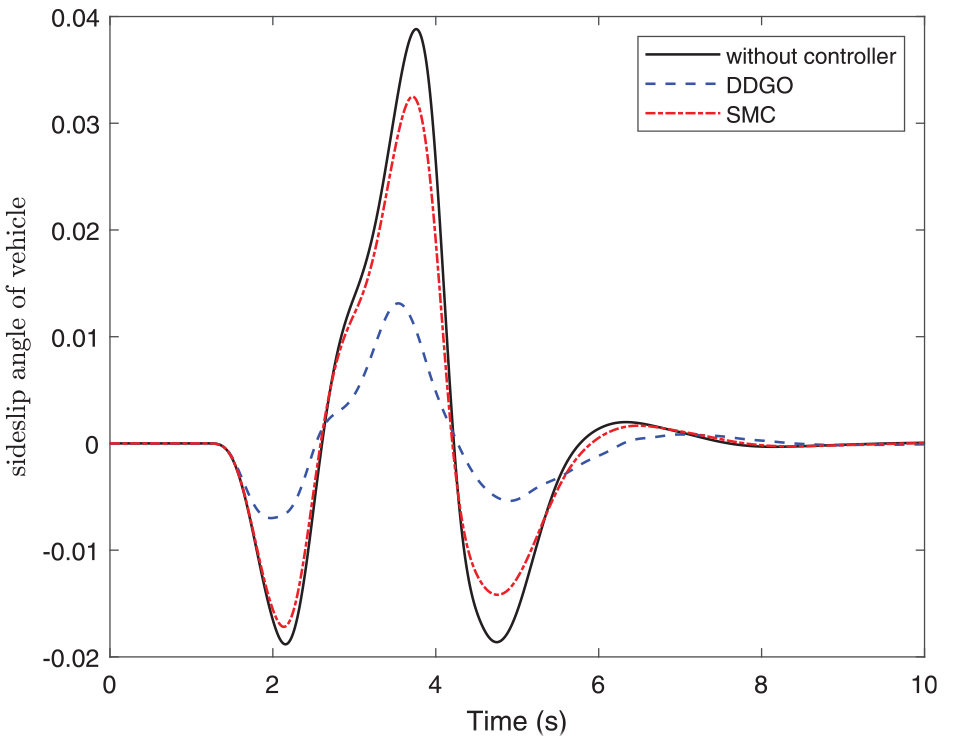
The sideslip angle with the DDGO controller and sliding mode controller at 120 km/h of co-simulation for double lane-change.
Analysis of steering wheel impulse input test
This test simulates a driver’s quick and sudden steering action in an emergency, such as avoiding an obstacle. In the simulation setup, the vehicle travels at a specified speed, and a sudden angular displacement is input to the steering wheel. The test focuses on the vehicle’s response speed, stability, and ability to return to a stable driving condition after the sudden steering input. The specific parameters of the impulse input in CarSim software are detailed in Figure 15.
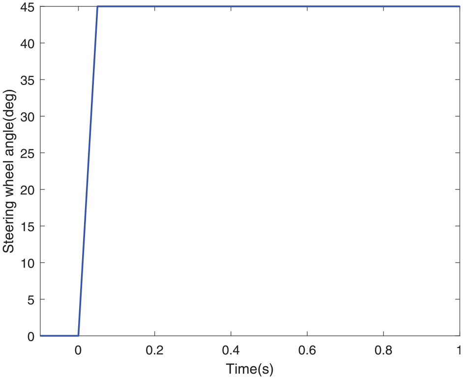
Steering wheel impulse input settings in CarSim.
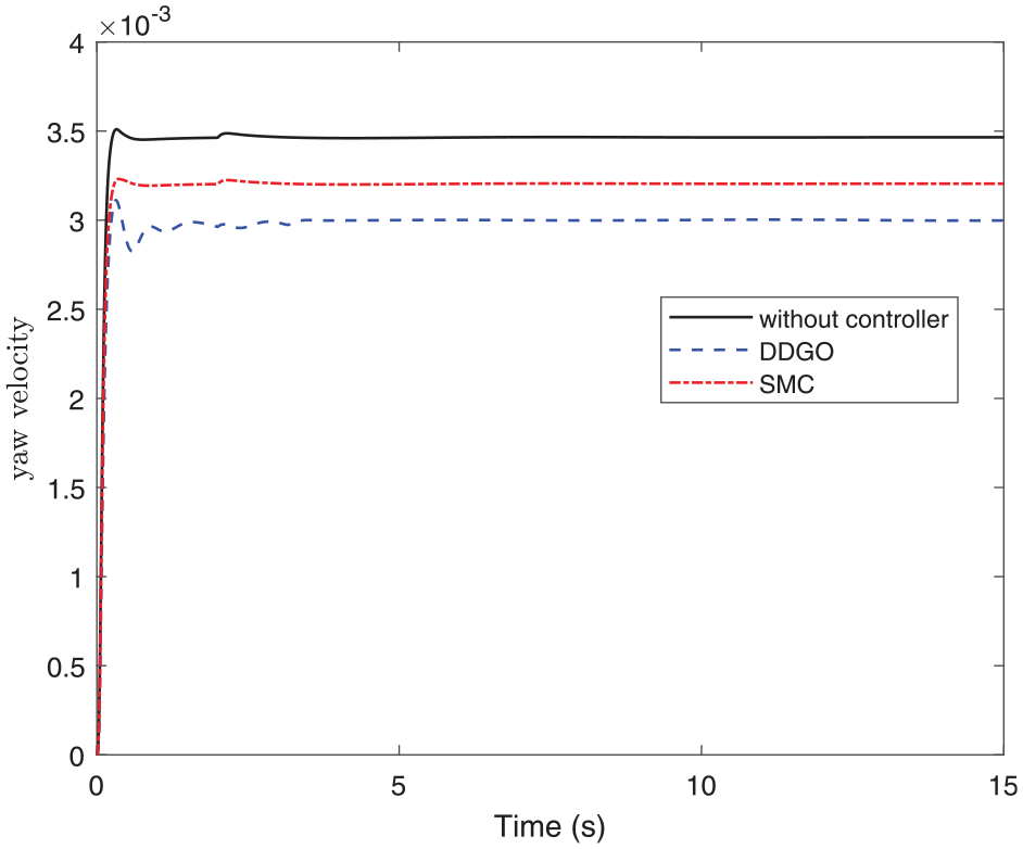
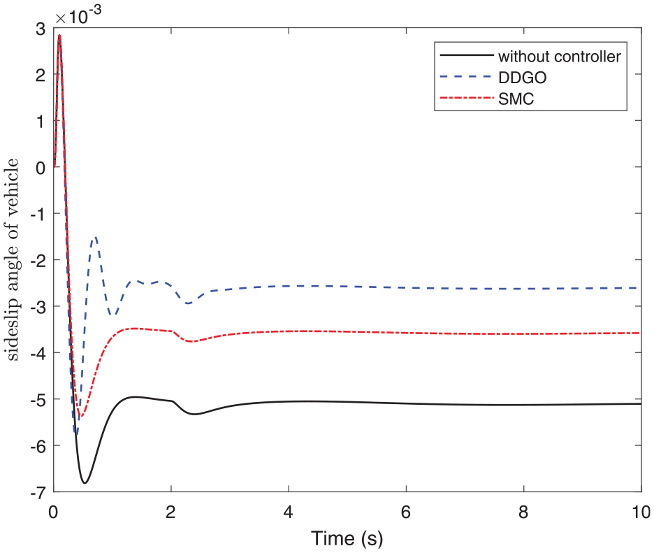
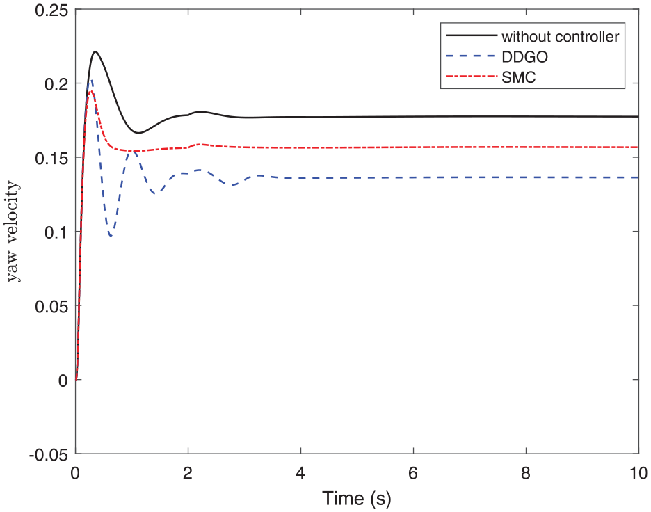
This set of simulations replicates angular step conditions. According to Figures 16 to 21, in terms of magnitude and fluctuation indices, the designed DDGO controller also exhibits effective control performance compared to the SMC method.
The yaw velocity with the DDGO controller and sliding mode controller at 60 km/h of co-simulation for steering wheel impulse input.
The sideslip angle with the DDGO controller and sliding mode controller at 60 km/h of co-simulation for steering wheel impulse input.
The yaw velocity with the DDGO controller and sliding mode controller at 80 km/h of co-simulation for steering wheel impulse input.
The sideslip angle with the DDGO controller and sliding mode controller at 80 km/h of co-simulation for steering wheel impulse input.
The yaw velocity with DDGO controller and sliding mode controller at 120 km/h of co-simulation for steering wheel impulse input.
The sideslip angle with the DDGO controller and sliding mode controller at 120 km/h of co-simulation for steering wheel impulse input.
In conclusion, the two controllers effectively enhance the lateral stability of the vehicle. The DDGO controller demonstrates superior performance compared to the sliding mode controller, as it effectively addresses the issues related to system time delay and unknown sensor measurement error.
Conclusion
In this paper, we propose a control method based on the dual control gain observer for vehicle lateral stability control. Firstly, we built a two-degree-of-freedom dynamic model considering unknown external disturbance for the lateral stability control. Based on the dynamic model, the lateral stability control system is constructed which considers unknown sensor measurement error and system time delay. A dual control gain observer and an output feedback controller are designed. And the designed controller is proven to globally asymptotically stabilize the system. Furthermore, we conduct simulations by software. The results demonstrate that the lateral stability control method based on dual domination gains observer significantly improves performance indicators such as yaw velocity and sideslip angle compared with the sliding mode controller.
Footnotes
Declaration of conflicting interests
The author(s) declared no potential conflicts of interest with respect to the research, authorship, and/or publication of this article.
Funding
The author(s) disclosed receipt of the following financial support for the research, authorship, and/or publication of this article: The work is partially supported by Zhejiang Provincial Natural Science Foundation of China under Grant No. LZ21E050002 and National Natural Science Foundation of China under Grant No. 62173208.
Data availability statement
Data can be requested and accessed from the authors.