Unknown failures and time delays of actuators which may degrade system performance seem inevitable in practical systems. However, the available results to compensate for unknown failures of time delay actuators based on adaptive approaches are very limited. In this paper, we address such a problem by considering controlling a class of second-order systems with unknown actuator failures and input delays. Firstly, the controlled system is transformed into a triangular structure model. Meanwhile, the input time delay is transformed into dynamics of the output signal. Then, an adaptive controller is developed using backstepping. Not only can the uncertainties due to actuator failure be compensated, but the unknown input delay has also been effectively restrained under the proposed control scheme. The upper bound condition of strength scalar is proposed. It is a sufficient condition for system stability. When the strength scalar satisfies this condition, the design parameters exist and the system is stable under the controlling of the proposed controller. Finally, the effectiveness of the proposed control scheme is verified through simulation results, including numerical simulation and actual system simulation. Through the comparative simulation, it can be seen that the control scheme proposed in this paper has faster convergence speed.
As we all known, time delay exists in all sorts of practical systems, for example, networked systems, mechanical systems, and biological systems and so on. Usually, such delay can not be measured during the operation of systems and it may affect the performance of the system. Therefore, the existence of time delay must be considered in controller design and stability analysis. In recent 20 years, several results have been established to different time delay systems,1–11 for example, coupled neural networks,1 uncertain neural systems,2 Markovian jump neural networks,3,4 switched fuzzy systems,5 discrete-time neural networks,6,7 and sliding mode method.8,9 The most common assumption about state time delay is that the delay parameter is a constant. This type of time delay is easy to handle in system design and analysis. Besides the constant state delay, the time-varying state delay also exists in the controlled system. With the enrichment of control theory and methods, many results have been achieved for state delay which exists only in system states. Compared with the research on state delay systems, there is still a lack of available processing methods for input delay.10 In a sense, input time delay can be seen as the uncertainty generated by the actuator in signal transmission. Throughout the research results of the control problems for nonlinear systems with input delay, most of them describe the time delay input as or . Different from this description, in this manuscript the unknown effects caused by input time delay are expressed as . An adaptive control is developed to compensate for the unknown effects caused by such time delay.
On the other hand, actuator failures12–24 also commonly occur in practical systems. Such failure is often uncertain in time, value and pattern and may lead to instability or even catastrophic accidents. In order to ensure the performance of the system in the event of actuator failure, the compensation control problem for unknown faults has recently received much attention. For unknown parameter changes caused by actuator faults, adaptive control technology can achieve dynamic estimation of fault parameters and avoid unnecessary false alarms and delays. So many results of failure compensation control based on adaptive technique have been proposed. It is because time delay and actuator faults are common in practical systems that the compensation control for unknown actuator failures of time-delay systems is more meaningful. For time-delay systems with unknown actuator faults,25–27 some results have been obtained in recent several years. In Refs.25,26 neural control method is used in the controller design. A class of non-strict feedback nonlinear systems is considered in Ref.25 and backstepping technique has also been used. In Ref.27 a fuzzy predictive fault-tolerant control scheme is proposed for a class of discrete-time nonlinear systems. Time delays and unknown failures are considered in the design of the controller. Time-delays considered in Refs.25–27 are only state delays, but not input delays. In other words, the available results about the adaptive controller design for time delay actuators are still limited because most of the approaches to deal with time delay are based on partial differential theory.
The author believes that unknown actuator faults and input delays may often coexist in practical systems. Sudden failures are inevitable during the operation of actuators, and input time delay can also be seen as a characteristic of generalized actuators. The characteristics of these two actuator ends are not independent and separable. The actuator fault will affect the form of uncertainty caused by the input delay, so the traditional method of dealing with the unknown delay cannot be used directly. Therefore, designing an adaptive controller to achieve fault compensation for input delay actuators has practical significance. Of course, the developed adaptive controller must ensure the stability of the closed-loop system. In controlled systems, we consider the input delay parameter being a variable of time . Based on the state space realization, we transform the input time delay uncertainties to state time delay. In this way, the unknown input time delay is transformed into dynamics acting on the output signal. Meanwhile, the converted controlled system has a triangular structure. Then an adaptive compensation control scheme is developed using backstepping approach28–32 under the unknown actuator failures. The stability of controlled systems can be guaranteed by the proposed control scheme whether actuator fails or not. We have summarized the following points in order to clearly demonstrate the contributions of this paper. (1) The adaptive compensation control problem is investigated for the second-order nonlinear system. The unknown faults of time delay actuators are considered. The uncertainties of the controlled system mainly come from unknown actuator faults and input delays of the actuators. These two types of uncertainty effects from actuators can interact with each other. This also makes the design of the backstepping controller more challenging. (2) The coefficient of the time-delay input term not only contains the unknown parameter but also the transfer-like function , which is their product. It is difficult to design adaptive controller by using the traditional backstepping method. Under the state-space realization, the uncertainty of input time delay is transformed into dynamics on the output signal. Then, the robustness of the standard backstepping controller is utilized to determine the uncertainty effects caused by the unknown actuator delay and faults. At the same time, online estimation of the parameter changes caused by actuator failures can also be realized. (3) The upper bound condition of strength scalar is proposed. This is a sufficient condition and the upper bound is a fixed constant. It means that as long as the strength scalar is less than or equal to , a stable controller can be found according to the control scheme proposed in this paper.
There are five sections in this paper. The class of second-order nonlinear system is described in Section II. The controlled system is given by a transfer function formal model. With the state-space realization, it is transformed into state space form. The uncertainty of input time delay is transformed into the unknown dynamics of the output signal. The first part of Section III shows the adaptive compensation control scheme, which includes the controller, and update laws. Theorem 1 provides the main results for the stability of closed-loop systems. Simulation studies are presented in Section IV, and conclusion is given in Section V.
Models and problem statement
As we all know, many practical systems has a second-order structure. Namely, its mathematical model is a second-order differential equation, for example,33,34 the gun control system of tank, the joint system of pneumatic muscle, etc. On the other hand, input delay is also a common phenomenon in practice, for example, the radar antenna control system shown in Ref.35
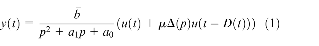
Because many systems have a second-order model in practice. So we consider the following class of second-order systems shown as the transfer function form in this paper.
where is the output. is the input signal. is unknown parameter and , are known constants. is a positive constant. is the input related uncertain term. is an unknown parameter representing input time delay. is the differential operator. is a rational function of . The term can be seen as the unmodeled dynamic and is a transformation operator for the input uncertainty with unknown time delay.
Remark 1:
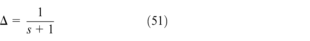
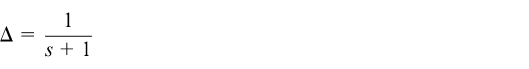
• Similar to Ref.,10 we suppose that is a rational fraction, strictly proper, and the real part of the solutions of the denominator polynomial is less than . As an example, if and , we obtain
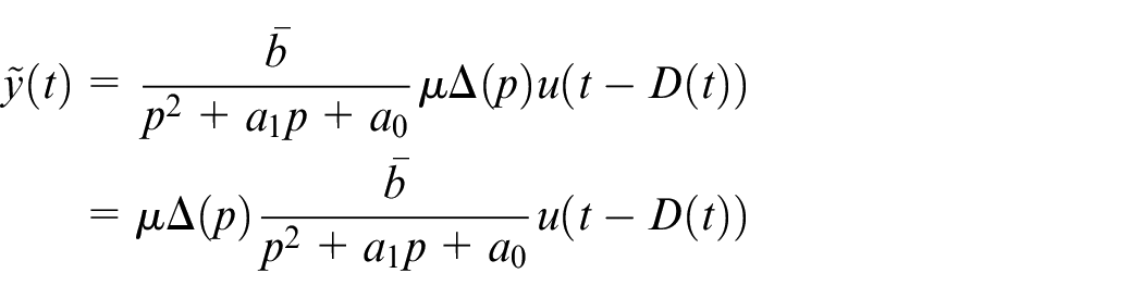
An uncertainty term is shown in the system model. Here such input delay can not be described as a precise mathematical model. is the scalar and represents the strength of the uncertain influence caused by .
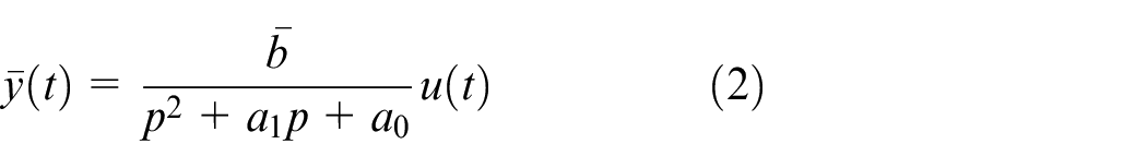
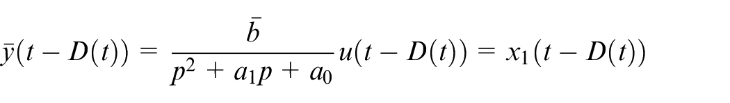
Note that the following transmission relationship of output signal and input
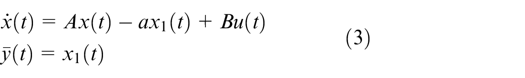
can be transformed as
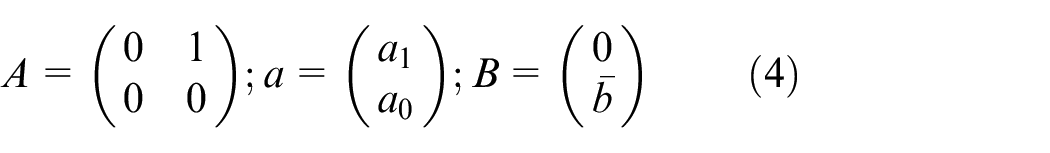
where is system state and
Under the running of system (3), we have
Then we let
To simplify, we let . Then we can get
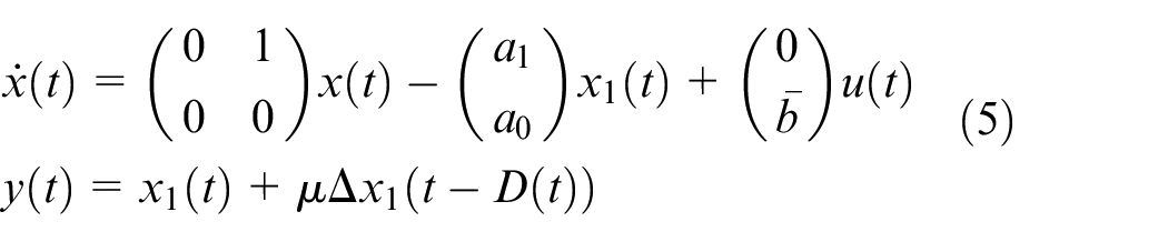
Noting that , system (1) can be transformed into the following state space realization similar to the nonlinear system shown in Refs.36,37:
Remark 2:
represents the unknown parameter about input time-delay. Here we consider is a variable of . can also be a constant. This is a special case of time-varying .
After the transformation, the uncertainty of input time delay is transformed into dynamics on the output signal. In the controller design and stability analysis, we will fully consider it. At the same time, system (1) is also transformed as a triangular structure shown in (5). The unknown parameters in (5) can be estimated by the dynamic update laws by the adaptive backstepping approaches.
The following assumptions are needed before we proceed the controller design.
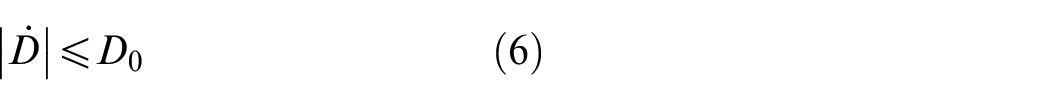
Assumption 1: The input time-delay such that
where is an unknown constant.
Assumption 2: The unknown parameter is non-zero and is known.
The inequality (6) shown in Assumption 1 is a common constraint on input time-varying delay38 and the Assumption 2 is frequently used in the controller design by backstepping.32 The requirement is reasonable because will be zero when . Obviously, Assumption 1 is satisfied when is a constant. Therefore, the proposed controller can also be applied to the case of constant input delay.
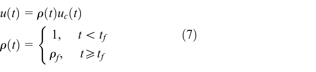
Now we consider the actuator may fail during its operation. The failure of actuator at time instant can be modeled as follows
where is the input of actuator and is the output of actuator. is an unknown constant. It is clear that is just the signal which will be acted on system. The unknown actuator failure shown in (7) represents the partial loss of effectiveness. This means that there will be a certain loss when the signal is transmitted through the actuator. At the same time, there is a certain time delay in signal transmission.
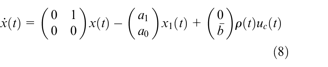
With the unknown failure shown in (7), the state equations of system can be rewritten as
Remark 3:
• The failure model given in equation (7) denotes actuators may lose its partial effectiveness. However, the time when the actuator malfunctioned is unknown. When an actuator failure occurs, the time delay of the input signal acting on the system by the actuator does not disappear. This time delay under the unknown actuator failures makes the control problem more difficult.
• D(t) represents input delay and is a sufficient smooth function of time variable t.
• In this paper, the range of (t) has been expended than existing result.10
To simplify, the general time variable will be omitted in the following Sections. For example, is written as . The time delay will be clearly remarked for delay dependent terms. For example, represents state with the time delay .
Design and analysis of adaptive controllers
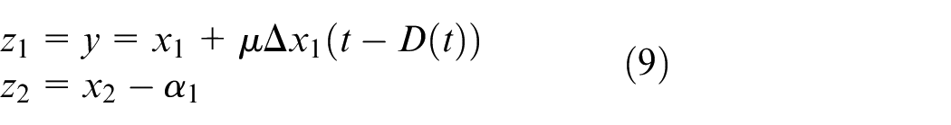
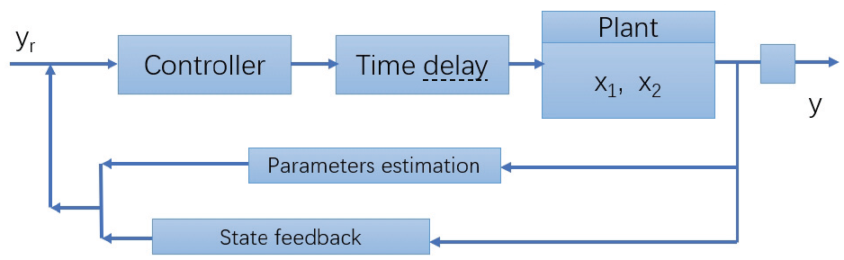
Our control purpose is to design an adaptive control law whose structure is shown in Figure 1 to ensure the system stability. The control scheme is developed by using backstepping techniques. The change of coordinates is important and given as follows:
where variable output and represents the virtual control.
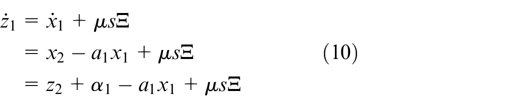
Step 1: With (5) and (8), we can get is
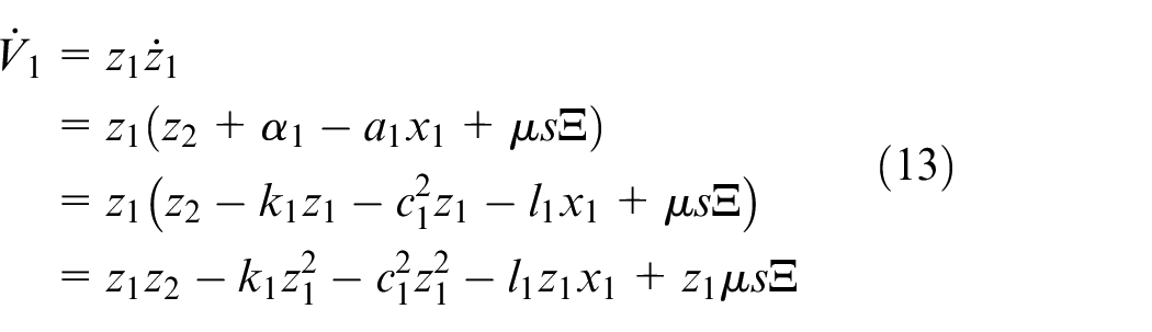
where is the virtual control. . We consider the following Lyapunov function
Block diagram of the adaptive controller.
can be chosen as
where are constant. Different from traditional backstepping, damping terms and have been introduced in the virtual control. These damping terms are mainly used to suppress the uncertainty caused by unknown input delays. This will be demonstrated in detail in the stability proof of the closed-loop system. is
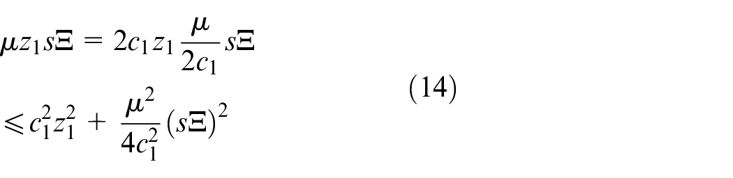
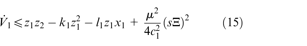
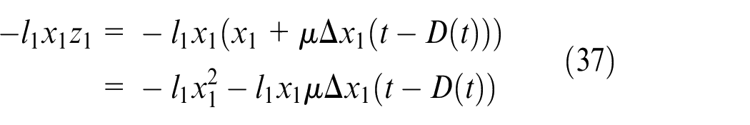
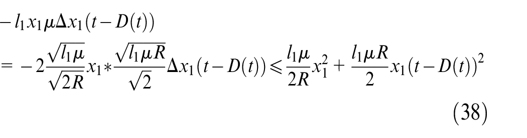
Note that
With (14) we can get
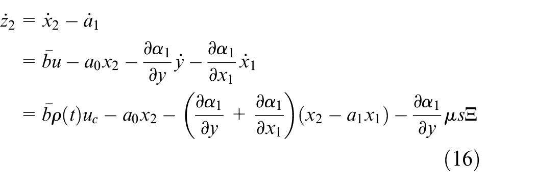
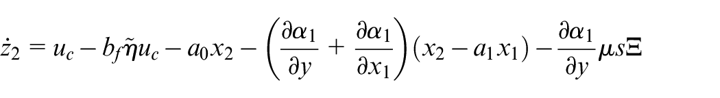
Step 2: From (8) and (9) the derivative of is
Letting , we have
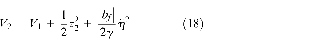
We consider the following Lyapunov function
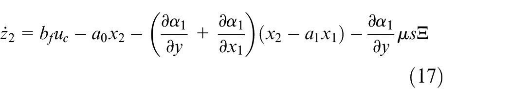
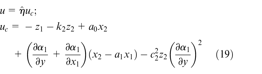
where and is the estimation of . is a constant. We directly provide the following adaptive control laws.
Control laws:
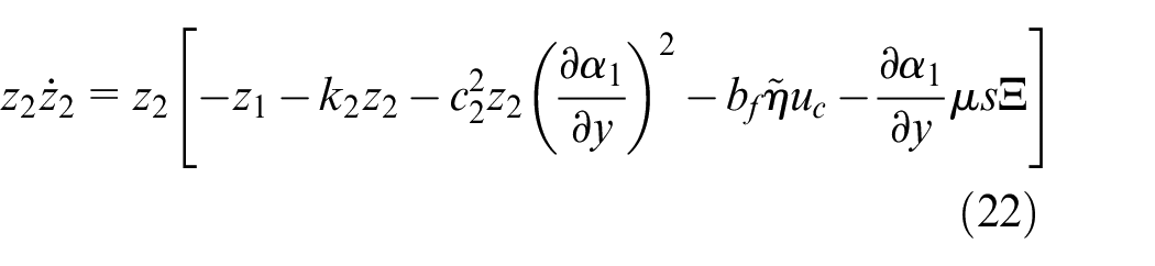
where are design parameters. The derivation of will be given below. From (18), the derivative of is
Note that
we have
Then with (19), we can get
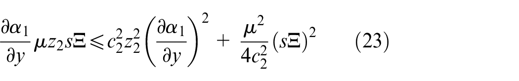
Note that
We have
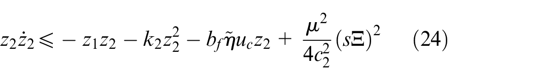
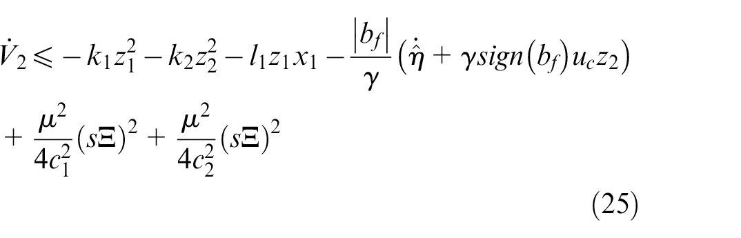
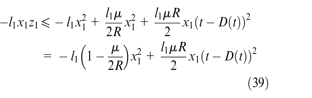
So we have
Because , we have
The derivative of can be rewritten as
Then we can get the update law of parameter
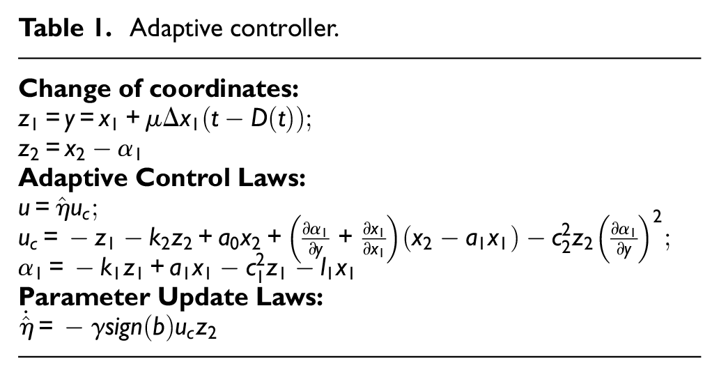
The controller design can be achieved by following the design procedures. It can be summarized in Table 1.
Adaptive controller.
Change of coordinates: Adaptive Control Laws: Parameter Update Laws:
Stability analysis
In the following part, the main results will be shown in the Theorem 1.
Theorem 1: Consider the closed loop system consisting of the system (5), controller (19) and update law (28). Under the Assumption 1 to Assumption 2, all the signals in the closed-loop system are globally bounded whether actuator failure occurs or not if satisfies where is any real number.
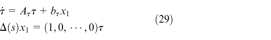
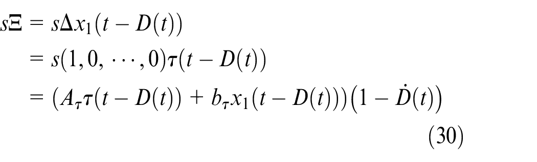
Proof: Signal is introduced to deal with the unmodeled dynamic . is generated by
where is design parameter. So we have
where is stable. Then we can get
where and are constants, and their values rely on .
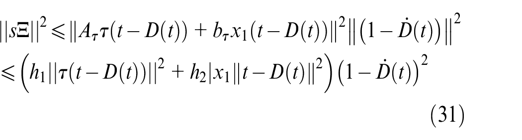
Remark 4: Since the unknown input delay is a function of the time variable, when the uncertain influence of the input delay is amplified, the derivative of the delay inevitably exists at the right end of the inequality, as shown in (31). In view of this situation, the delayed derivative term is introduced in the selection of design parameters. It is a more precise limitation given in (41) for selecting design parameters.
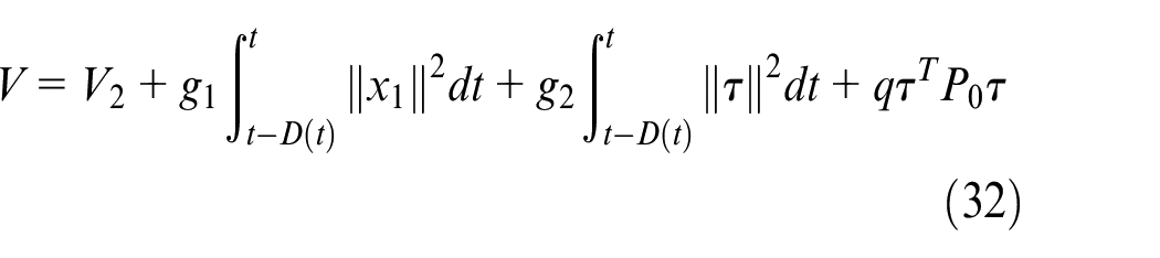
Choosing the following Lyapunov function
where are constants. satisfies
Then the is
So when we choose design parameter
we have
Note that
and
where is a constant. So we can get
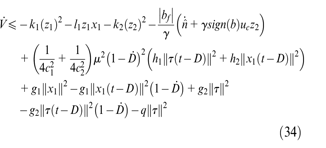
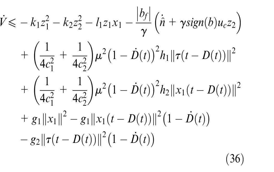
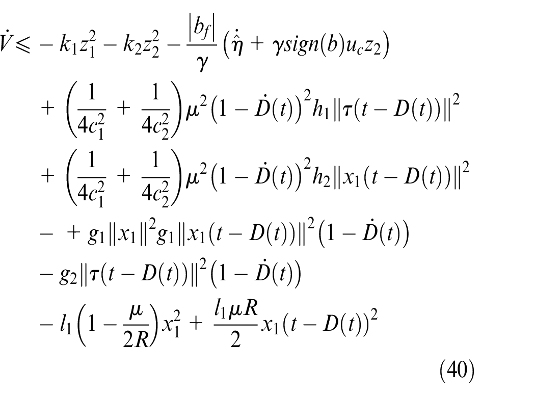
With (36) and (39) we can get
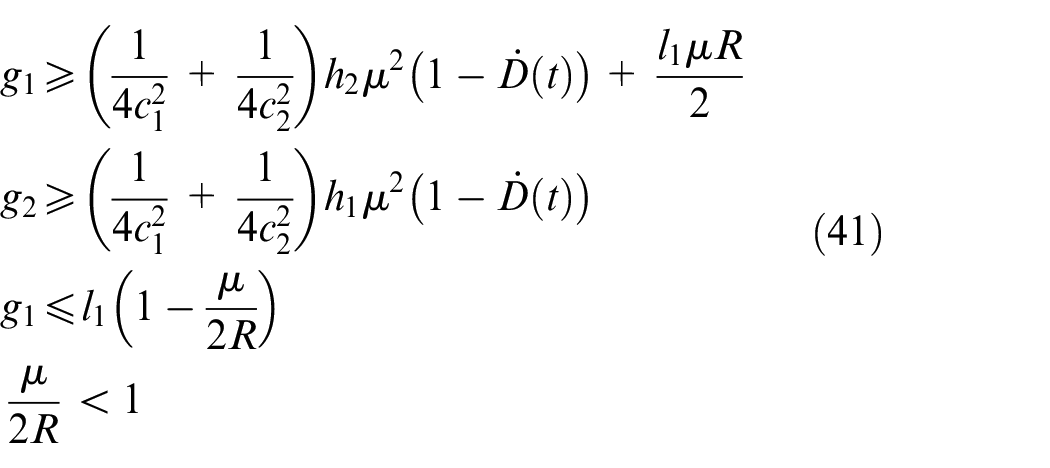
When design parameters satisfies
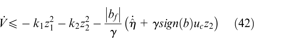
The derivative of can be rewritten as
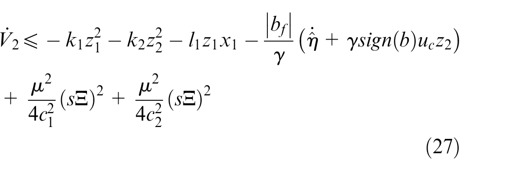
With update law (28), we have
Form the requirements on design parameters (35) and (41), we know that the key to the existence of design parameters is that the following inequality is satisfied.
Namely
Clearly
Actually, we can make the value of being any positive small by choosing appropriate and . So we need to satisfy
Namely
Then
So all design parameters exist when where is any real number less than or equal to . ▪
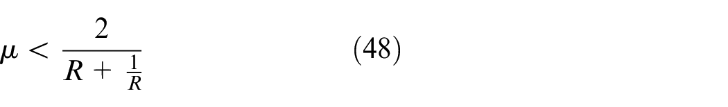
Remark 5: Compared with the existing result shown in Ref.,10 the upper bound of has been given based on the analysis shown above. It is worth noting that whether is known or unknown, as long as the upper bound of is less than or equal to 1, the stable controller of the system exists. It also means that the stability of any nonlinear systems will be destroyed when the influence scale of unmodeled dynamics is big enough.
Sometimes the value of is difficult to know or impossible to know. At this time, the result shown in Theorem 1 is not meaningless. The result of the paper indicates that the designed adaptive controller is robust to the uncertainty effects caused by input delayed. As long as the magnitude of the input delay uncertainty satisfies , the stability of the system can be guaranteed by the proposed control law.
Remark 6:Equation (41) provides a set of inequality constraints for the design parameters. It is a condition that the stable controller must meet. It is also the key to obtaining a stable adaptive control law. In other words, we should select parameters according to equation (41). When is known, we let , otherwise we take . According to our experience, a practical method is to set . Then we can find the values of design parameters according to equation (41).
Simulation studies
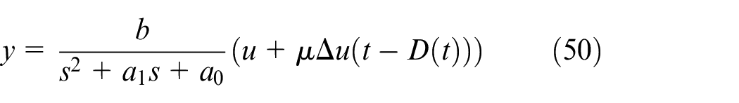
Next, simulation analysis will be provided. The simulation results include numerical simulation, actual system simulation, and comparative analysis. We consider the second-order system shown as follows:
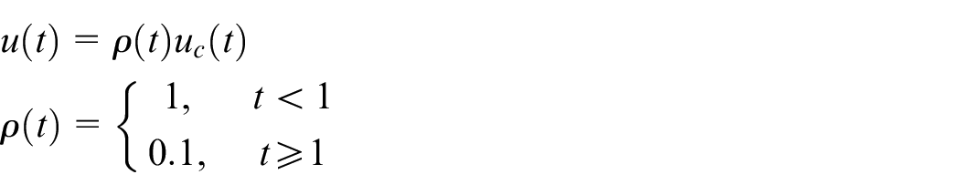
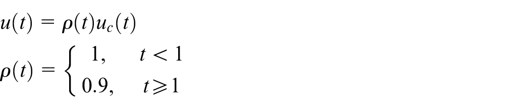
where are known constants. is unknown parameters and the value of is . We take . Thus can be taken as and is less than 1. is dynamic. We take its value as
In simulation we take . The design parameters are selected as , , , . We let . The actuator failure is
Stability simulation
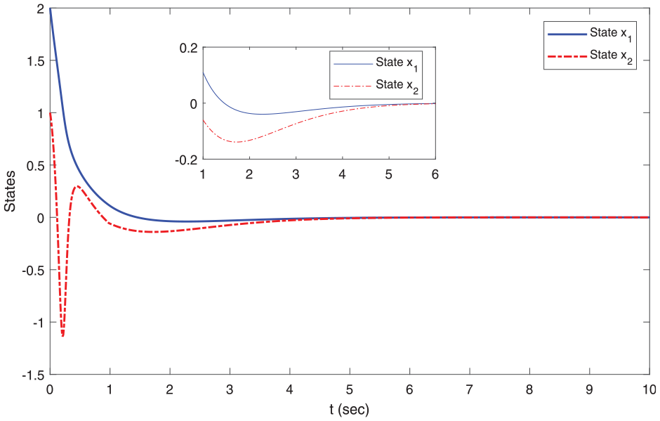
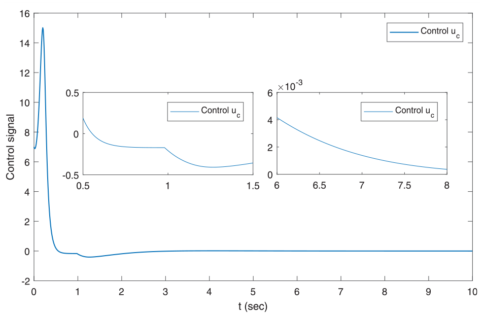
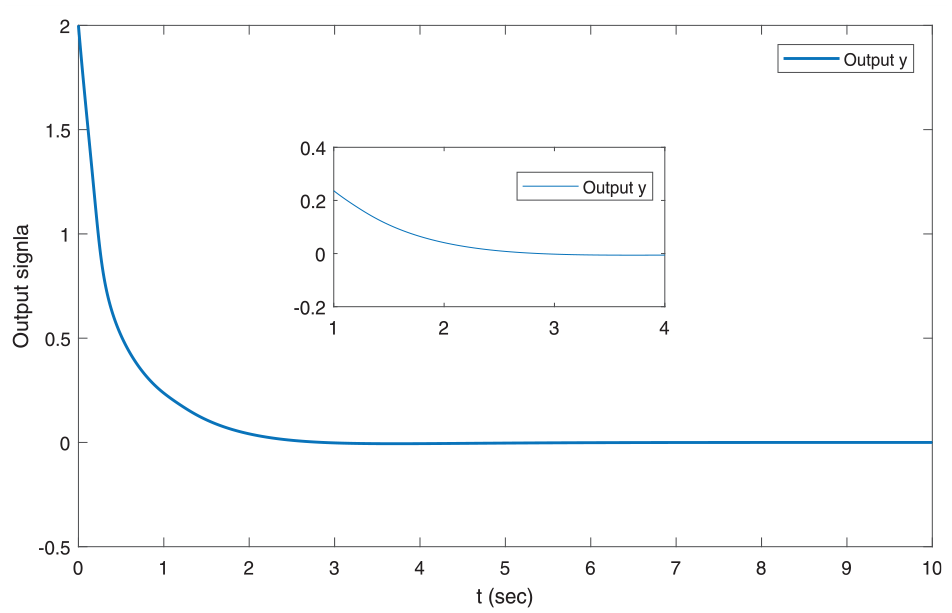
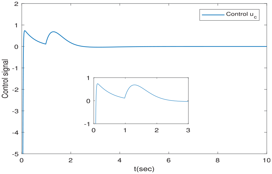
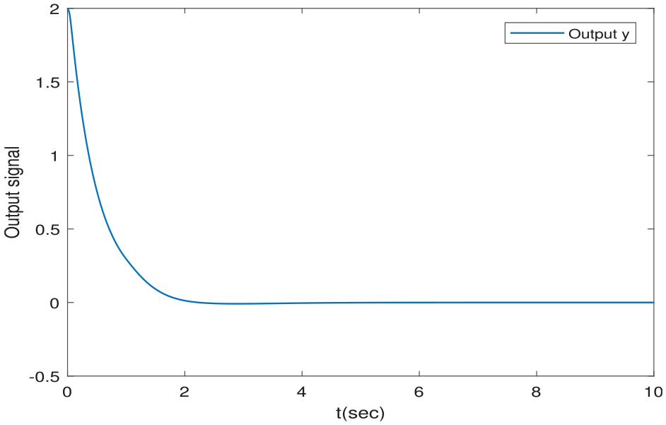
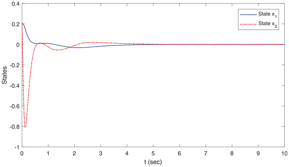
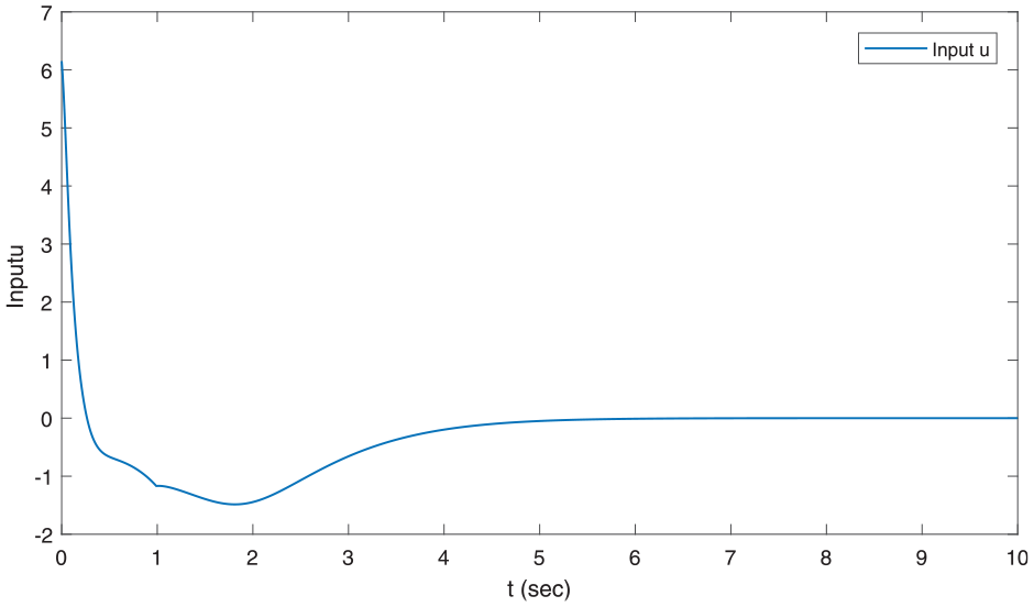
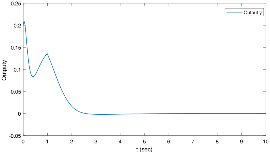
The simulation results are given in Figures 2 to 4. Figure 2 shows and while Figure 3 shows the system input. It is easy to see that states and input signal are all bounded. The output signal given in (5) is shown in Figure 4. It is also bounded with unmodeled dynamics. Therefore, we can get that the controlled system is stable under the controlling of the proposed controller.
States of stability simulation ().
Input of stability simulation ().
Output of stability simulation ().
In control system (50), we take . Then the control system becomes . Obviously, the system is stable. The design parameters and initial values remain unchanged. The following simulation results shown in Figures 5 to 7 can be obtained. It is easy to see that the performance of the system has not changed much.
States of stability simulation ().
Input of stability simulation ().
Output of stability simulation ().
Comparative simulation
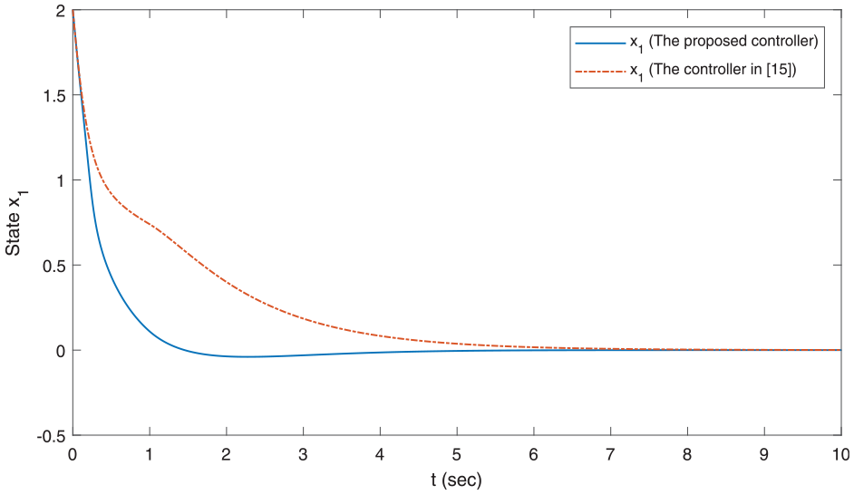
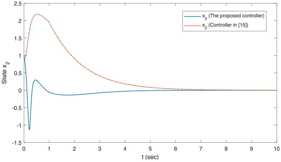
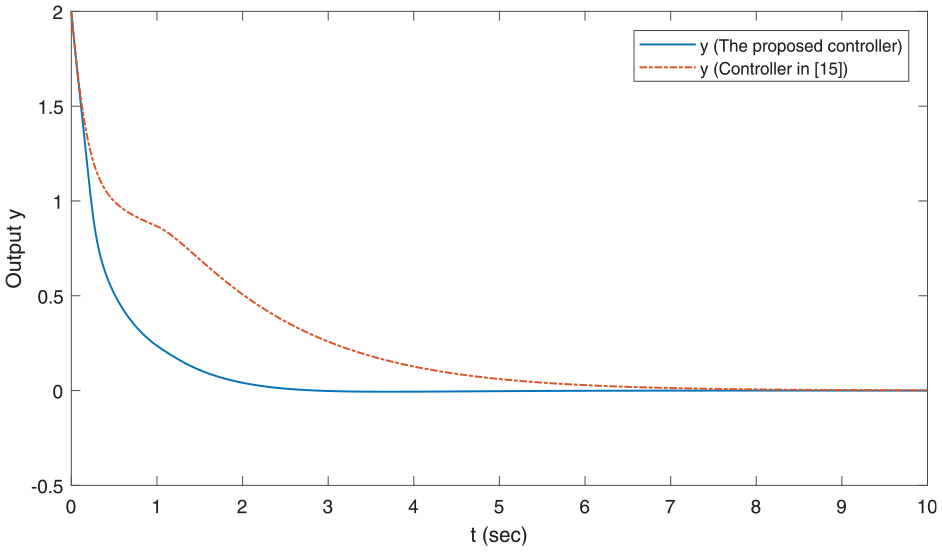
To illustrate the effectiveness of the proposed control scheme in this paper, the compared simulation has been made between the proposed scheme and the approach of controller design shown in Ref.15 In the proposed control scheme, the design parameters are selected as , , , . The initial values are set . In controller shown in Ref.,15 the design parameters are selected as ( in Ref.15 are equivalent to that of in this proposed controller) and (the design parameter in the update law of the parameter estimation). the initial values are set as . The actuator fault parameters and input delay parameters are the same as the above stability simulation.
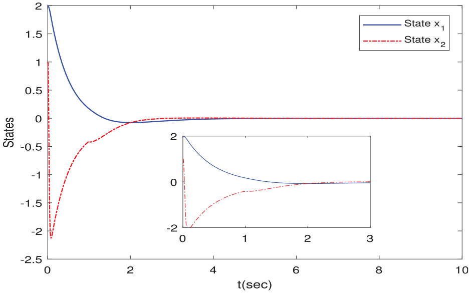
Simulation results including system states and output signal have been shown in Figures 8 to 10, respectively. Under the controller proposed in this paper, states (Figures 8 and 9) will reach stability faster. Obviously, the output signal (Figure 10) has the same properties. Then we can conclude that system performances are clearly very poor and far from satisfactory when we apply the controller given in Ref.15
State of comparative simulation.
State of comparative simulation.
Output of comparative simulation.
The controller shown in Ref.15 is an adaptive compensation control scheme for unknown actuator failures. It did not take into account the existence of input delay. Unlike the control scheme in Ref.15 the controller proposed in this paper takes into account both actuator faults and the uncertainty caused by input delay. Therefore, the controller proposed in this article can achieve better system performance.
Actual system simulation
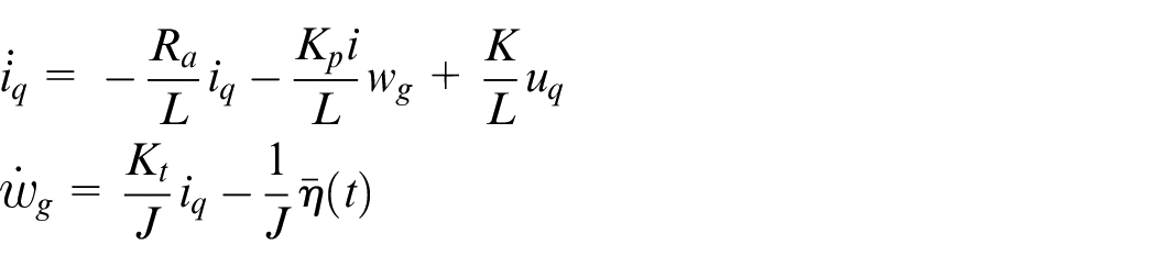
Next we will consider the following tank gun control system shown in Ref.33 in the simulation analysis.
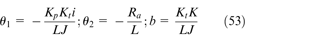
where and are the torque coefficient and inductance of motor. is the armature resistance. is the inertia of total load. is the EMF coefficient. is the reduction ratio. represents all uncertainties. is the angular velocity.
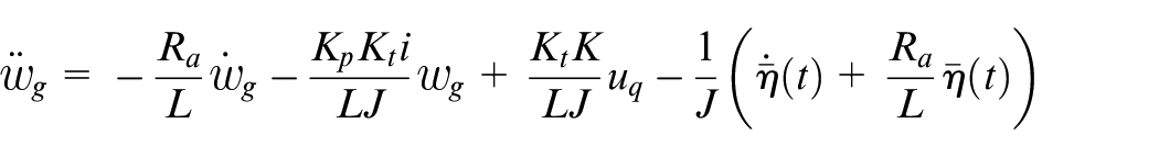
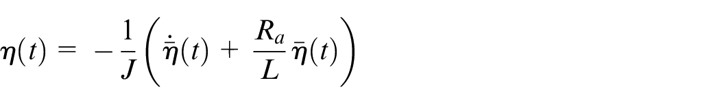
By simplification, we can obtain
Let
and
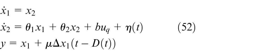
The following system model can be obtained. The first system state represents the angular velocity of gun and the second system state is the acceleration. Input delay is taken into account in the tank gan control system. In order to directly utilize the controller proposed in this paper, the above tank gun control system is rewritten as
where is system state and is the output. is the input delay. The scalar parameter . are known and can be obtained by
where these parameters mainly come from engineering practice39 and are taken as: , , , , , , and . is dynamic. We take its value as
The uncertainty term is ignored in simulation. We take the values of design parameters as , , , . The initial values are chosen to be . The actuator failure is
The electric control signal of servo motor is the input signal of controlled system. Figure 11 are angular velocity and acceleration of gun. Figure 12 is the electric control signal of servo motor and Figure 13 is the output signal. From the results shown in Figures 11 and 13, we know that angular velocity, acceleration signal of gun and the output of the controlled system can quickly stabilize to a very small range of 0 within 4 s. Even in the presence of unknown input delays and actuator failures, the developed control scheme can ensure the performance of the controlled system. The electric control signal of servo motor is also in a stable amplitude state after 4 s.
States and of actual system simulation.
Input of actual system simulation.
Output of actual system simulation.
Conclusion
In this paper, the adaptive control problem has been researched for second order nonlinear systems. The stabilization of closed-loop systems can be guaranteed by the proposed control law and corresponding update laws. Not only can the uncertainties due to actuator failure be compensated, but the unknown input delay has also been effectively restrained under the proposed control scheme. It is worth noting that the adaptive control scheme proposed in this manuscript is invalid when parameters in system (1) are unknown. Thus to develop an adaptive update laws of unknown parameters is a possible future work. In addition, modeling errors and external disturbances are commonly present in actual systems. The effects of these uncertainties should be fully considered in controller design. This is also the problem we need to address in depth next.
Footnotes
Declaration of conflicting interests
The author(s) declared no potential conflicts of interest with respect to the research, authorship, and/or publication of this article.
Funding
The author(s) disclosed receipt of the following financial support for the research, authorship, and/or publication of this article: This work was partially supported by the Zhejiang Provincial Natural Science Foundation of China (Grant No. LY22F030011, LZ22F030008) and Key R&D Program of Zhejiang (2022C02035).
ORCID iD
Jianping Cai
Data availability statement
Data sharing not applicable to this article as no datasets were generated or analyzed during the current study.
References
1.
XuYLuRShiP, et al. Robust estimation for neural networks with randomly occurring distributed delays and markovian jump coupling. IEEE Trans Neural Netw Learn Syst2018; 29(4): 845–855.
2.
LuRWuHBaiJ.New delay-dependent robust stability criteria for uncertain neutral systems with mixed delays. J Franklin Inst2014; 351(3): 1386–1399.
3.
WuZGShiPSuH, et al. Stochastic synchronization of Markovian jump neural networks with time-varying delay using sampled data. IEEE Trans Cybern2013; 43(6): 1796–1806.
4.
ZhangMShiPLiuZ, et al. Dissipativity-based asynchronous control of discrete-time Markov jump systems with mixed time delays. Int J Robust Nonlinear Control2018; 28(6): 2161–2171.
5.
ZhangMShiPLiuZ, et al. H∞ filtering for discrete-time switched fuzzy systems with randomly occurring time-varying delay and packet dropouts. Signal Process2018; 143(6): 320–327.
6.
LiJNLiLS.Mean-square exponential stability for stochastic discrete-time recurrent neural networks with mixed time delays. Neurocomputing2015; 151: 790–797.
7.
WuZGShiPSuH, et al. Passivity analysis for discrete-time stochastic Markovian jump neural networks with mixed time delays. IEEE Trans Neural Netw2011; 22(10): 1566–1575.
8.
GanjefarSSarajchiMHHamidi BeheshtiMT.Adaptive sliding mode controller design for nonlinear teleoperation systems using singular perturbation method. Nonlinear Dyn2015; 81(3): 1435–1452.
9.
GanjefarSSarajchiMHMahmoud HoseiniS.Teleoperation systems design using singular perturbation method and sliding mode controllers. J Dyn Syst Meas Control2014; 136(5): 051005.
10.
ZhouJWenCWangW.Adaptive backstepping control of uncertain systems with unknown input time-delay. Automatica2009; 45(6): 1415–1422.
11.
ZhuYKrsticMSuH.Delay-adaptive control for linear systems with distributed input delays. Automatica2020; 116: 1–9.
12.
TongSHuoBLiY.Observer-based adaptive decentralized fuzzy fault-tolerant control of nonlinear large-scale systems with actuator failures. IEEE Trans Fuzzy Syst2014; 22(1): 1–15.
13.
LiYTongS.Adaptive neural networks decentralized FTC design for nonstrict-feedback nonlinear interconnected large-scale systems against actuator faults. IEEE Trans Neural Netw Learn Syst2017; 28(11): 2541–2554.
14.
WangWWenC. A new approach to adaptive actuator failure compnsation in uncertain systems. In: IEEE International conference on control and automation (ICCA 2009), 2009, pp.47–52. New York: IEEE.
15.
CaiJPWenCSuHY, et al. Adaptive failure compensation of hysteric actuators in controlling uncertain nonlinear systems. In: Proceedings of the 2011 American control conference, 2011, pp.2320–2325. New York: IEEE.
16.
WangWWenC.Adaptive actuator failure compensation control of uncertain nonlinear systems with guaranteed transient performance. Automatica2010; 46(12): 2082–2091.
17.
WangWWenC. Adaptive output feedback controller design for a class of uncertain nonlinear systems with actuator failures. In: Proceedings of the 49th IEEE conference on decision and control, 2010, pp.1749–1754. New York: IEEE.
18.
WangWWenCYangG. Stability analysis of decentralized adaptive backstepping control systems with actuator failures. In: Proceedings of the 27th Chinese control conference, 2008, pp.497–501.
19.
CaiJPWenCSuHY, et al. Robust adaptive failure compensation of hysteretic actuators for parametric strict feedback systems. In: Proceedings of the 2011 50th IEEE conference on decision and control and european control conference (CDC-ECC), 2011, pp.7988–7993
20.
CaiJWenCSuH, et al. Robust adaptive failure compensation of hysteretic actuators for a class of uncertain nonlinear systems. IEEE Trans Automat Contr2013; 58(9): 2388–2394.
21.
ZhangMShiPShenC, et al. Static output feedback control of switched nonlinear systems with actuator faults. IEEE Trans Fuzzy Syst2020; 28(8): 1600–1609.
22.
LiJNGuKYLiuX, et al. Asynchronous adaptive fault-tolerant control for markov jump systems with actuator failures and unknown nonlinear disturbances. Complexity2020; 2020: 1–10.
23.
LiMShiPLiuM, et al. Event-triggered-based adaptive sliding mode control for T–S fuzzy systems with actuator failures and signal quantization. IEEE Trans Fuzzy Syst2021; 29(6): 1363–1374.
24.
DiaoSSunWSuSF, et al. Adaptive fuzzy event-triggered control for single-link flexible-joint robots with actuator failures. IEEE Trans Cybern2022; 52(8): 7231–7241.
25.
ZhangYWangF.Adaptive neural control of non-strict feedback system with actuator failures and time-varying delays. Appl Math Comput2019; 362: 124512–12.
26.
ZhouCFangMXiaJ, et al. Fault-tolerant output-feedback stabilization for complex-valued neural networks with time delay and actuator failures. AIP Adv2019; 9: 1–9.
27.
ShiHLiPSuC, et al. Fuzzy Predictive Fault-tolerant control for Time-Delay nonlinear systems with partial actuator failures. Complexity2019; 2019: 1–20.
28.
CaiJPWenCYSuHY, et al. Robust adaptive backstepping control of second-order nonlinear systems with non-triangular structure. In: Proc. 19th IFAC world congress, 2014, pp. 10814–10819.
29.
CaiJWenCSuH, et al. Adaptive backstepping control for a class of nonlinear systems with non-triangular structural uncertainties. IEEE Trans Automat Contr2017; 62(10): 5220–5526.
30.
CaiJWenCXingL, et al. Decentralized backstepping control for interconnected systems with non-triangular structural uncertainties. IEEE Trans Automat Contr2023; 68(3): 1692–1699.
31.
CaiJMeiCYanQ.Semi-global adaptive backstepping control for parametric strict-feedback systems with non-triangular structural uncertainties. ISA Trans2022; 126: 180–189.
32.
ZhouJWenC.Adaptive backstepping control of uncertain systems. Verlag, Berlin, Heidelberg: Springer, 2007.
33.
CaiJYuRYanQ, et al. Event-triggered adaptive control for tank gun control systems. IEEE Access2019; 7: 17517–17523.
34.
CaiJPXingLZhangM, et al. Adaptive neural network control for missile systems with unknown hysteresis input. IEEE Access2017; 5: 15839–15847.
35.
ZhangWLiZ.Design and simulation analysis of fuzzy self-adaptive PID controller in radar antenna control system. Comput Meas Control2011; 19(9): 2173–2175.
36.
HeSFangHZhangM, et al. Adaptive optimal control for a class of nonlinear systems: the online policy iteration approach. IEEE Trans Neural Netw Learn Syst2020; 31(2): 549–558.
37.
HeSFangHZhangM, et al. Online policy iterative-based H∞ optimization algorithm for a class of nonlinear systems. Inf Sci2019; 495(2): 1–13.
38.
KrsticM.Delay compensation for nonlinear, adaptive, and PDE systems. Berlin: Birkhauser Boston, 2009.
39.
LiangFLeiXMMaXJ.Adaptive sliding mode robust control of gun control system of tank. Fire Control Command Control2010; 35(10): 55–58.