
Abstract
Hydraulic active suspension has the coupling characteristics of integrated mechanical-hydraulic-control system, and its performance is also affected by external interference, noise interference, and other factors. Therefore, a novel controller is presented to achieve system-level optimal performances by using the collaborative control method. The proposed collaborative method is provided an implementation framework, and includes outer loop control of Linear Quadratic Regulator (LQR), inside loop control of modified linearized active disturbance rejection control (M-LADRC) and Kalman filter, and so on. In addition, the semi-physical simulation method is used to the simulation and test, and the force tracking control test for hydraulic servo system and Kalman filter test are carried out. Finally, the performance of semi-physical active suspension is compared with that of the ideal active suspension and passive suspension under the different road profile excitation. The superiority and effectiveness are verified for the collaborative control method. The collaborative controller has improved the suspension system performance and is more practical, which is beneficial for the application of the achievements.
Introduction
In the field of vehicle dynamics, the main research focuses on the vehicles’ suspension system, aiming at improving the comfort, safety, and handling capability. The main forms of suspension system include the passive, semi-active, and active. The active suspension is an advanced suspension that can regulate the operating force according to the vehicle driving state, compared to semi-active and passive suspension systems. The active suspension system, comprising primarily actuators, sensors, controllers, and other components, represents an advanced form of suspension technology. It can control and adjust the vehicle’s body and suspension in real-time based on the road surface, vehicle status, and other pertinent information. At the same time, it can offset the effect of road impact, so that the vehicle can ensure good comfort, safety, and handling capability, and its vibration reduction effect is significantly better than passive suspension and semi-active suspension. The research indicates that the vehicle performance is significantly improved after being equipped with active suspension.1–3 The active suspension system has garnered significant attention from researchers dedicated to enhancing the ride comfort, handling performance, and safety of vehicles.1,4
In recent years, various control algorithms and strategies for active suspension systems have been introduced to enhance vehicle ride comfort, operational stability, safety, and maneuverability.5–8 Significant research efforts have focused on possible control algorithms, for example, adaptive control,9,10 H∞ control,11,12 robust control, 13 preview control, 1 optimal control,1,14 and intelligent control.15,16 In Ref., 17 for active suspension systems, a sliding mode control method based on the dynamics of hydraulic actuators is proposed. In Ref., 18 the adaptive sliding mode control method of T-S fuzzy nonlinear active suspension system was presented. Successful results have been reported using various active suspension system control strategies.9,19,20 The main research is based on model-free active suspension systems.1,21,22 For example, in Ref., 23 a stochastic estimation approach for a potential sensor scheme is proposed for active suspension systems, leveraging optimal preview control. In Ref., 24 a novel vibration suppression technique that integrates passive and active methods is introduced, aiming to enhance the balance between dynamic performance and control demands. A multi-objective control approach for vehicle suspension, leveraging wheelbase previewing information was introduced in Ref. 25 The study employed a 4 degrees of freedom semi-vehicle model.
However, the actual active suspension system usually has the characteristics of parameter uncertainty (such as the change of suspension parameters), noise, external interference, non-ideal actuators (such as nonlinear, hysteresis), and so on, which always significantly reduces the suspension performance in practical applications.26,27 In Refs.,28,29 the researchers developed detailed models of the hydraulic actuation systems for single, dual and tri-axis vehicle suspensions, which could be used for further analysis and control system design. By connecting the upper and lower chambers of the double-acting hydraulic cylinders diagonally, they established a mathematical model to calculate the hydraulic pressure and anti-roll moment, based on the hydraulic oil flow dynamics and gas state equations. In Ref., 19 an adaptive tracking control method is proposed specifically for non-ideal actuator active suspension systems, which can effectively eliminate unexpected nonlinear effects and improve vehicle suspension performance. In order to enhance the ride comfort and handling capability of active hydro-suspension systems within constrained flutter space and allowable tire dynamic load limits, an adaptive backstepping sliding mode bottom controller based on projection was proposed to adjust valve current and drive asymmetric actuators accurately tracking the desired target force under time-varying fluid parameters. 30 To address the issue of uncertainty and external interference commonly encountered in suspension systems, a study investigates an output feedback finite-time control method. This method aims to stabilize disturbed automotive active suspension systems, thereby enhancing suspension performance. Additionally, a disturbance compensator is introduced to effectively counteract unknown external interferences. 31 In Ref., 32 a model-free fuzzy logic controller, termed PSO-MFFLC (Particle Swarm Optimization-based Model-Free Fuzzy Logic Controller), is introduced. This controller accounts for the nonlinearity of the active suspension system, including parameter variations, external disturbances, and frictional forces.
Although these existing works have achieved better active suspension control performance in the field of vehicles, there are still some important problems that need to be further discussed. For example, in the existing work, the hydraulic actuator of the active suspension has been always considered as an ideal actuator. However, in the actual control practice for active suspension, the use of hydraulic actuators also needs to consider its dynamic response. The good dynamic response for the actuator means that the actuation force tracking effect is better. The paper 33 proposes a simple and low-computational-cost prescribed performance control method without approximation, based on high-gain observers (HGO) and prescribed performance functions, which can effectively improve suspension performance while reducing computational burden. In Refs.34,35 respectively introduce the application of model-driven and data-driven active disturbance rejection control in intelligent power generation systems. The results show a significant improvement in system stability and robustness, highlighting the advantages of these methods in addressing system uncertainties. In Ref. 36 proposes an LADRC method that integrates active damping (AD), internal model control (IMC), and sliding mode control (SMC), effectively suppressing disturbances and improving the tracking accuracy of servo systems. A variable form linear active disturbance rejection control (VFLADRC) method, integrating extended state differential compensation and feedforward control, is proposed to enhance the robustness and output dynamic performance of the electrical load interface unit in a microgrid. 37 In this paper, an improved force tracking control method (Modified LADRC, simplified to M-LADRC) for the active suspension system is proposed to enhance the hydraulic actuation force control performance. Compared with the existing hydraulic active suspension system, the algorithm for force tracking control has a better effect, and it fully considers the dynamics of the hydraulic actuator in the actual practice. In addition, in the active suspension actual control practice, the control signal and the dynamic signal contain different levels of noise. Therefore, a Kalman filtering method is proposed.
The main contributions of this paper to the hydraulic active suspension system are as follows:
A collaborative control method is proposed, which includes outer-loop LQR control, inner-loop improved linear active disturbance rejection control (M-LADRC), and Kalman filtering. This collaborative control strategy comprehensively considers factors such as system modeling information, external disturbances, and noise effects.
The M-LADRC controller is designed to incorporate the model information of the electro-hydraulic servo system into the LADRC algorithm, enhancing the force tracking control performance of the hydraulic actuator.
The Kalman filtering algorithm is used to filter road noise and sensor measurement noise, improving the robustness of the system.
The dynamic performance of the hydraulic active suspension system is evaluated through hardware-in-the-loop simulation, verifying the superiority and effectiveness of the proposed collaborative control method.
This research lays a theoretical foundation for the practical engineering application of hydraulic active suspension systems, facilitating the promotion and application of related results.
The rest of this paper is structured as follows. The LQR and LADRC control methods are introduced in Section 2. In Section 3, we introduce the hydraulic servo system model and the electro-hydraulic actuator model for active suspension. Additionally, we present the design of an improved active disturbance rejection controller aimed at tracking the hydraulic actuation force. In Section 4, the 1/4 dynamic model is introduced, and the LQR controller and Kalman filter are designed. Section 5 is results analyzes for the simulation and test. Finally, Section 6 presents some conclusions.
Methodology
The active suspension is a hydraulic active suspension, and the actuator is a symmetrical hydraulic cylinder. The actuator and the passive suspension are connected in parallel, and the electro-hydraulic servo valve of the suspension controls the hydraulic cylinder, and then the hydraulic cylinder generates the required actuation force. The amplifiers of electro-hydraulic servo valve can amplify the weak electrical signals to control hydraulic energy with high energy density. Its working principle is to change the displacement of slide valve, so that the flow and direction of the hydraulic oil entering the hydraulic cylinder are changed to control the actuation force. The hydraulic actuator outputs the actuation force and is a significant component of the active suspension. The input to the hydraulic cylinder is comprised of oil flow and pressure, and the output is the actuation force. In Figure 1, a collaborative control method of LQR and M-LADRC for hydraulic active suspension is shown. The hydraulic active suspension adopts dual-loop control system, including an inside loop controller and an outer loop controller. The inside loop controller is to make the actuator produce the actual actuation force to track the expected actuation force by controlled the servo valve. In the inner loop controller, the M-LADRC control algorithm is used to track the target force. Additionally, it incorporates an extended state observer (ESO) to mitigate the effects of various components of the dynamic system. The outer loop controller primarily computes the expected optimal actuation force based on the vehicle state and a comprehensive performance evaluation index. Furthermore, in outer loop control, the optimal actuation force is obtained by the LQR control algorithm. In addition, in active suspension actual control practice, the control signal and the dynamic signal contain different levels of noise. Therefore, a Kalman filtering method is used to filter pavement noise and sensor measurement noise.
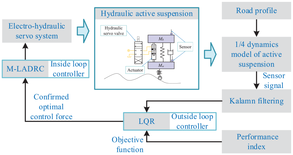
A collaborative control method of LQR and M-LADRC.
Actuation force tracking control for electro-hydraulic servo system
Electro-hydraulic servo system model
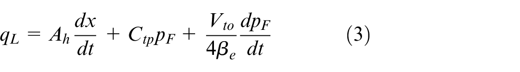
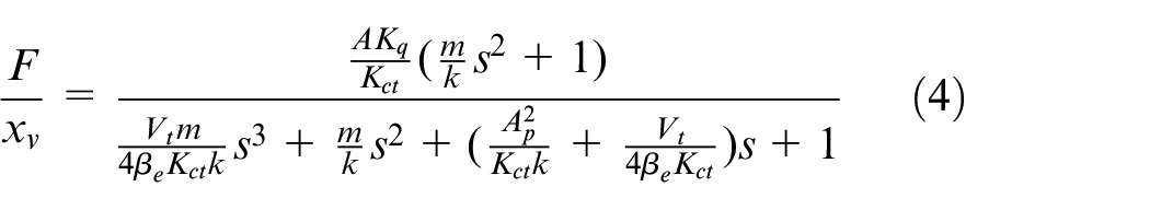
The system model mainly includes two parts, which are servo valve model and symmetrical hydraulic cylinder model. The transfer function modeling has been adopted for electro-hydraulic servo system, and the symmetrical hydraulic cylinder model is obtained according to transfer function of three basic equations by Laplace transform. The three equations can be obtained about the electro-hydraulic servo system consist of the linearized equation regarding flow-pressure, the force balance equation, and the flow continuity equation of the hydraulic cylinder.

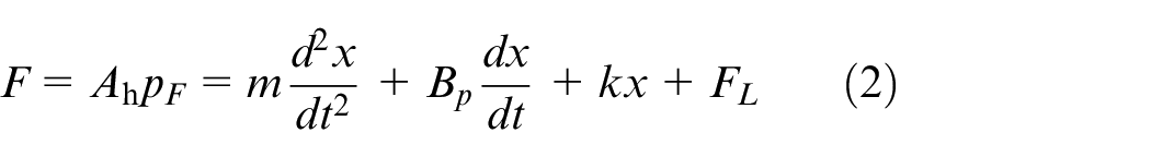
where
Assuming that the initial position of each equation is zero, and the corresponding derivative is zero at the zero position. In addition, the load damping coefficient
Where,
The transfer function of the servo valve is as follows:
where,
Following the system modeling of the electro-hydraulic servo, each module is connected to deduce the block diagram of the system transfer function can be derived, as depicted in Figure 2.

Transfer function block diagram of electro-hydraulic servo system.
M-LADRC controller
The ADRC is a control theory combines classical control theory and modern control theory. The fundamental concept of Active Disturbance Rejection Control (ADRC) revolves around adopting the simple integral tandem type as the standard configuration. 38 The different parts of the dynamics system are estimated and eliminated by using ESO in real time, and the total disturbance is regarded as a whole, so that the controlled object is restored to the standard integral tandem type. 39 In ADRC, ESO adopts the Function Adaptive Law (FLA) based on nonlinear structure. The Extended State Observer (ESO) can effectively compensate for both unknown model dynamics and external disturbances. It uses a small gain to reduce overcorrection in the case of large error and large gain to speed up the system response in the case of small error. However, this nonlinear structure leads to many control parameters, which is not conducive to engineering realization. In order to overcome the limitation of nonlinear ADRC, a linearized ADRC (LADRC) is proposed by associating ADRC parameters with frequency. 40 In LADRC, the design of the LESO and controller depends only on the bandwidth of controller and observer, and the control parameters are reduced to several by constructing the controller and the expanding state observer. 41
The linear active disturbance rejection controller of hydraulic active suspension is designed. According to a property of Laplace transform, the transfer function of electro-hydraulic servo system is transformed into differential equation.
Because the high order coefficient
Add the total disturbance to the system, and the equation can be rearranged to give:
where,
In the controller design of LADRC, the accuracy of LESO’s estimation of system disturbance determines the quality of the controller. The previous LADRC controller does not need to consider the parameters of the model and is a model-free controller, which is also the advantage of LADRC. But it also increases the difficulty and accuracy of LESO’s estimation of disturbance. Therefore, the LADRC algorithm is improved in this paper (M-LADRC). The transfer function of electro-hydraulic servo system has been deduced above. Therefore, when designing the LESO, control system information can be incorporated into the LESO, which enhances both the dynamic and static response performance of the system, and improves system robustness.
The improvement is that the linear model the electro-hydraulic servo system was integrated into the M-LADRC controller, but the precise model of the electro-hydraulic servo system is not required. The LESO can estimate and eliminate the parts of the system dynamics that deviate from the standard type in real time, treat the total disturbance as a whole, and restore the controlled object to the standard PD controller. If the model system information is not added, the control effect is not very different for low order simple systems. However, for complex higher-order systems, the addition of model information is more accurate, the system has a stronger anti-interference ability, the system overshoot is smaller, and the robustness is better.
PD controller form is:

Where,
It is assumed that
The system disturbance is added to the state-space equations, and the state variable of the system is
Similarly, the state-space equation of the linear extended observer is identified as follows:
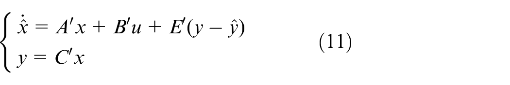
Equation (11) can be rearranged to give
All the selected eigenvalues of

Finally, the observer gain matrix of the system is
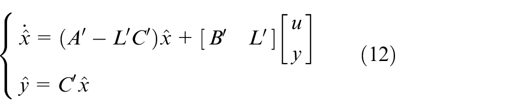
The design of the linear controller is similar to the former LADRC, and the system input control signal from the controller can be expressed as
where,
According to the design and analysis of the modified LADRC, the electro-hydraulic servo system model information was integrated into M-LADRC control algorithm. M-LADRC controller contains model information, which can be partial information or all information. For complex systems, the more model information included in M-LADRC controller, the better the control effect. Therefore, for the electro-hydraulic servo system, the structure diagram of the improved linear active disturbance rejection controller is illustrated in Figure 3.

M-LADRC structure diagram of electro-hydraulic servo system.
Active suspension model, LQR controller and Kalman filter
Hydraulic active suspension model
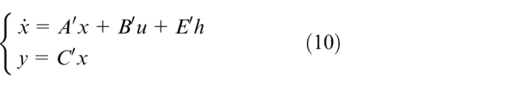
The hydraulic active suspension adopts the parallel structure of the passive suspension and the hydraulic actuator, which has the advantage that the switching modes of the active suspension system have active mode and passive mode, which can be selected according to actual needs. When the suspension actuator fails or active control is not required, the system can continue to operate using the passive suspension. The dynamic differential equation of the active suspension can be established by adding the active force to the dynamic differential equation of the passive suspension. Before establishing the model, the system should be reasonably simplified. and its differential equation is shown in equation (15).
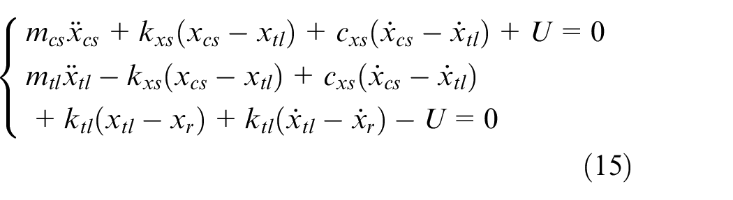
where,
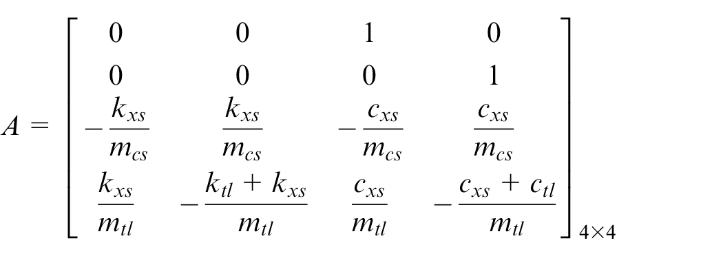
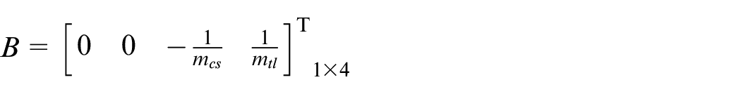
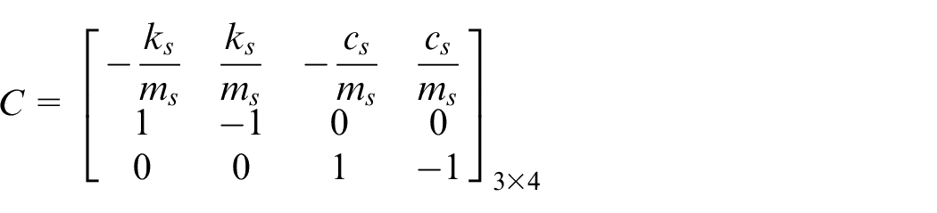
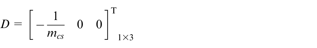
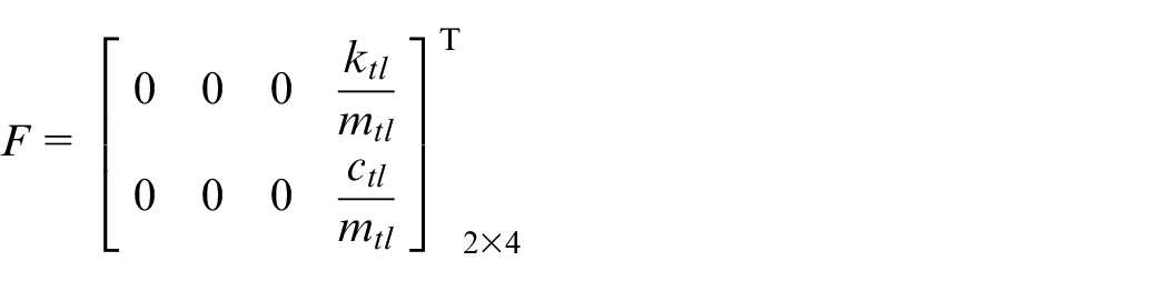
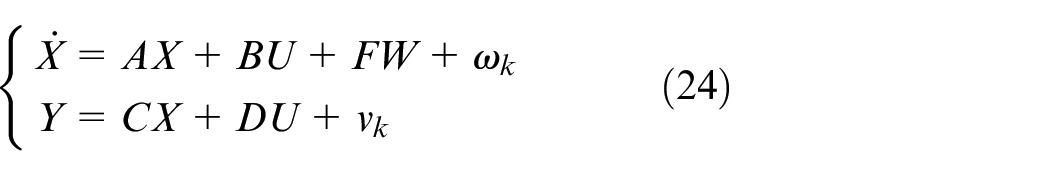
According to the dynamic differential equation, the state space expression is obtained, where
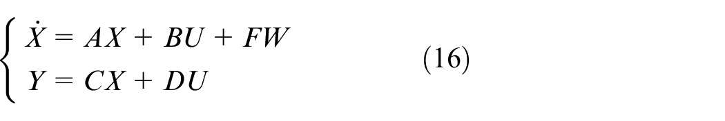
A, B, C, D, Y, X, and F are as follows


LQR controller
LQR control is a modern control theory,42,43 which uses the maximum principle and dynamic programing to select an admissible control U according to the mathematical model of a given controlled object, and minimizes the multi-objective performance function J under the initial, end and boundary constraints. LQR control is a widely used control algorithm at present, which is easy to implement in engineering. 44 It can ensure the real-time performance of the controller, and is suitable for multi-objective optimization for linear systems. Therefore, the LQR control algorithm is selected as the outer loop algorithm of the control strategy to calculate the optimal actuation force U in this paper.
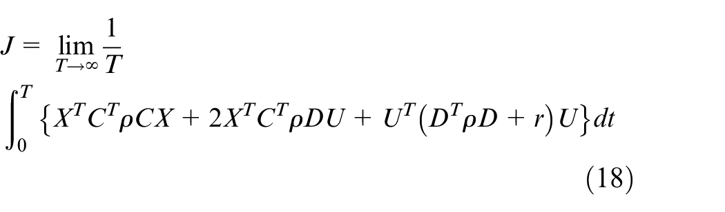
Based on the performance evaluation index of the active suspension, the objective is to minimize the body vertical acceleration, suspension travel, and wheel speed. Therefore, its performance functional can be expressed as:
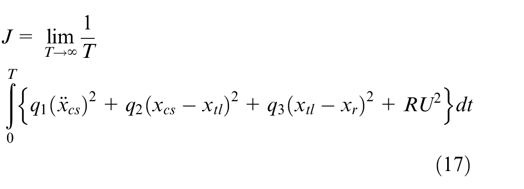
where,
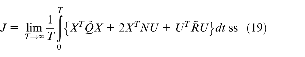
By converting the performance index functional into standard type, we have:
Let
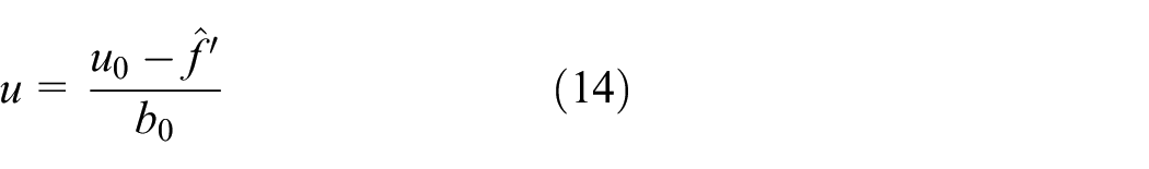
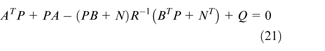
Assuming that the state of the system can be measured, then in order to minimize the suspension performance index function, its control output force U is:

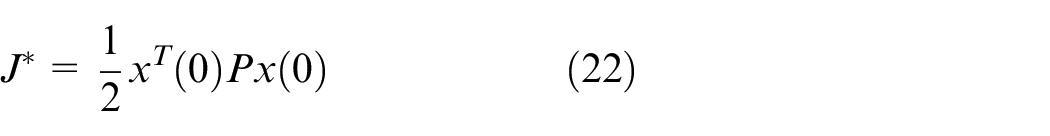
In this case, the optimal performance index is:
Taking the limitations into account about the vehicle total power, the provided active actuation force is limited. Therefore, the following conditions should be met:

where, f min and f max are the minimum and maximum external forces provided by the actuator respectively.
Kalman filter
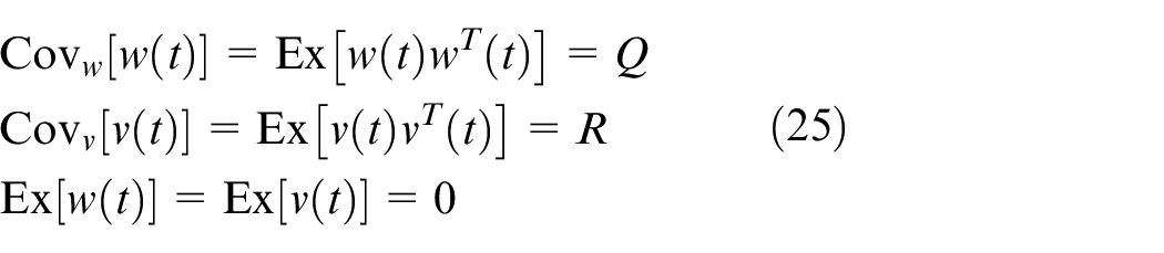
The principle of Kalman filtering is to filter the system output noise and estimate the system state quantity according to the state space equation.45,46 This algorithm is widely used because of its high reliability and low cost. Considering the influence of pavement noise and sensor measurement noise, the system state space equation of the dynamics model can be expressed as:
where,
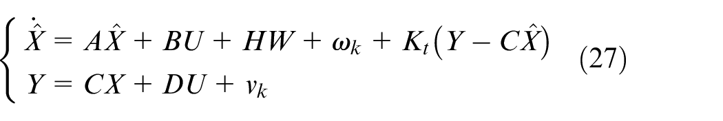
The state estimation modification expression can be expressed as:

where,
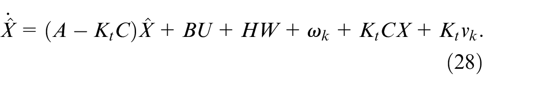
By the mode estimation modification expression and equation (24), we have
where, D is the zero matrix, we have,
Kalman filter gain

where, M is a Riccati equation solution.

Combining LQR control algorithm and Kalman filter algorithm for active suspension, the state estimation and control schematic diagram of LQR active suspension based on Kalman filter can be obtained, as illustrated in Figure 4.
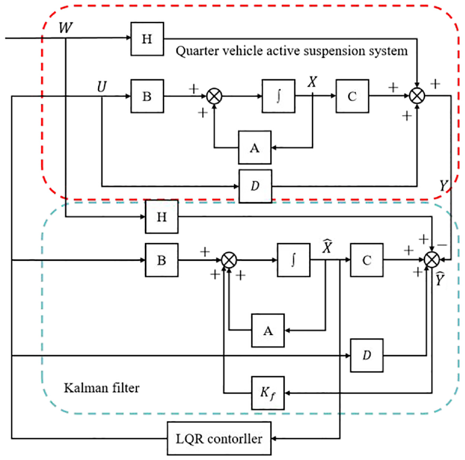
Schematic diagram of LQR active suspension based on Kalman filter.
Simulation and test
Test scheme
Semi-physical simulation is an experimental method that combines hardware microcontroller with software simulation environment. For example, in Ref., 48 a semi-physical virtual simulation system has been proposed for three-machine integrated coal mining equipment based on Unity3D, incorporating an actual hardware control system to provide theoretical and technical support for the intelligence and automation of mining production. Paper 49 proposes a semi-physical simulation method that integrates an actual photovoltaic thermal system and heat pump with a virtual fuel cell model, constructing a semi-physical simulation platform to study the coordinated control strategies of multi-energy coupling systems. In the research of electro-hydraulic servo system, the semi-physical simulation is faster, more efficient and safer than the traditional physical system. It can verify the algorithm correctness quickly and adjust the control algorithm parameters reasonably. Processor-in-the-loop (PIL) is a semi-physical simulation. The physical model of the electro-hydraulic active suspension has been established by Simulink/Simscape platform, and the model parameters were consistent with the real objects as far as possible. The control algorithm code is transplanted to STM32 MCU. The architecture of STM32 and the semi-physical simulation model is shown in Figure 5. This method uses STM32 single chip microcomputer as the hardware platform, and realizes the simulation and control of the hardware system through communication and data interaction with the physical model in Simulink software. In addition, the influence of time delay for the control algorithm is also included in the process of data communication. During the experiment, parameters of serial port are configured to realize data interaction.
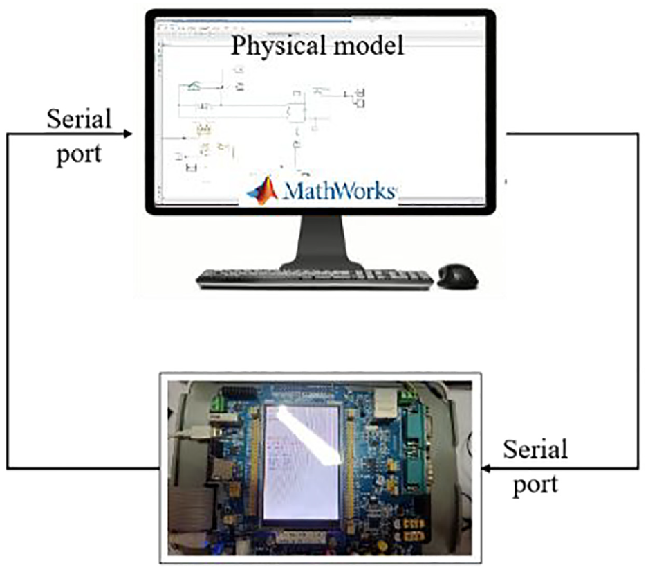
Semi-physical simulation of active suspension system.
In the Simulink simulation environment, the built-in serial communication modules—serial receive, serial send, and serial configuration—were used to configure the serial port parameters and achieve data interaction. The data transmission and reception were tested in the Simulink environment. As shown in Figure 6, the data is first sent from the computer to the microcontroller. Upon receiving the data, the microcontroller immediately sends it back to the computer. The data transmission and reception results are shown in Figure 7. The tests demonstrated good communication between Simulink and the microcontroller, although there is some delay.

Serial communication test model.
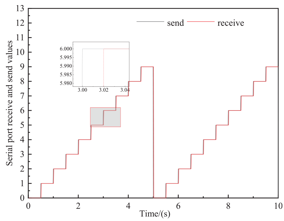
Serial communication data transmission and reception.
Active force tracking control test
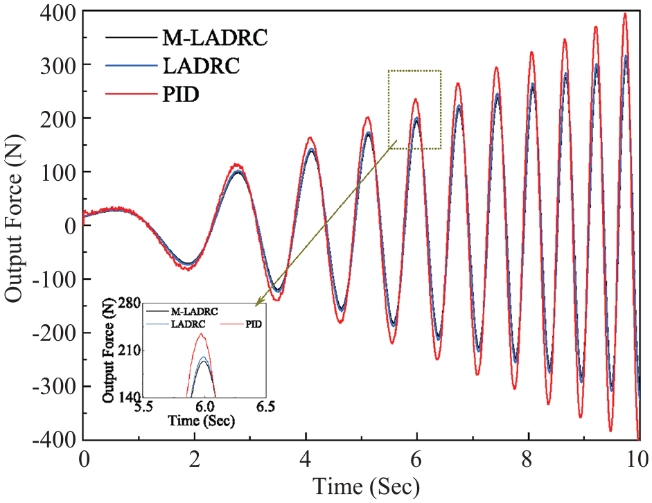
According to section 3, the force tracking model of actuator is presented in MATLAB/Simulink platform. In this paper, a sweeping target force signal is set, its amplitude is 5000 N, the initial frequency is 0.1 Hz, and the end frequency is 2 Hz. The force tracking control test is carried out. By comparing the three control algorithms about LADRC, M-LADRC, and PID, the tracking curve, and tracking error curve of the sweep signal can be obtained, as shown in Figures 8 and 9 respectively. The results showed that the tracking effect of the three algorithms deteriorates with the increase of the sweep frequency, but the tracking accuracy of the M- LADRC is the highest.
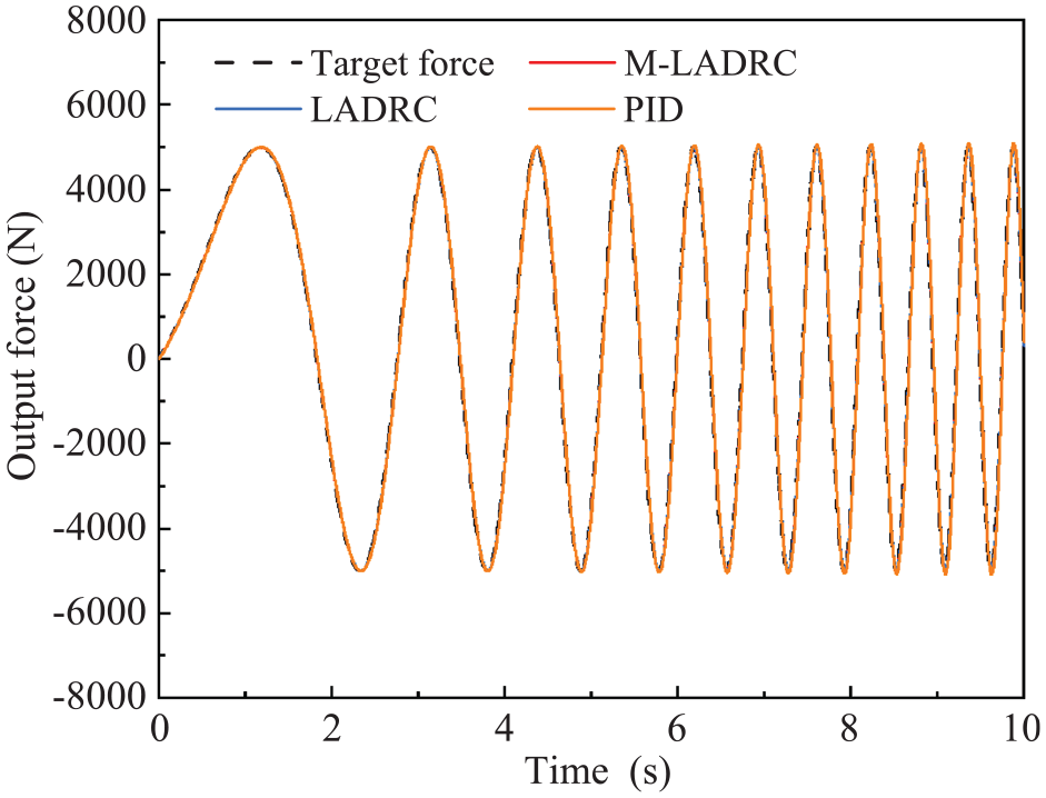
Force tracking curves under sweep signal.
Force tracking error curves under swept signal.
A target square wave signal with an amplitude of 5000N and a frequency of 0.2 Hz was selected for the tracking test. In Figure 10, by comparing the three control algorithms about LADRC, M-LADRC, and PID, the tracking curve under the square wave signal can be observed. The tracking error of LADRC control algorithm is very large, and LADRC outputs highly jittery signals. The reason for the large tracking error is the total power limitation. The power limiting module is set in the simulation model, which limits the maximum output voltage, resulting in the maximum forward output force only 2920 N. The M-LADRC tracking effect is very good, with the output showing almost no overshoot, and the system response speed is fast. However, PID control algorithm is seriously overshoot. The above analysis shows that M-LADRC has better tracking performance and anti-interference ability than PID, which is suitable for the electro-hydraulic servo model with nonlinear, uncertainty, and disturbance in the actual model. The superiority of M-LADRC algorithm is verified by experimental comparison.
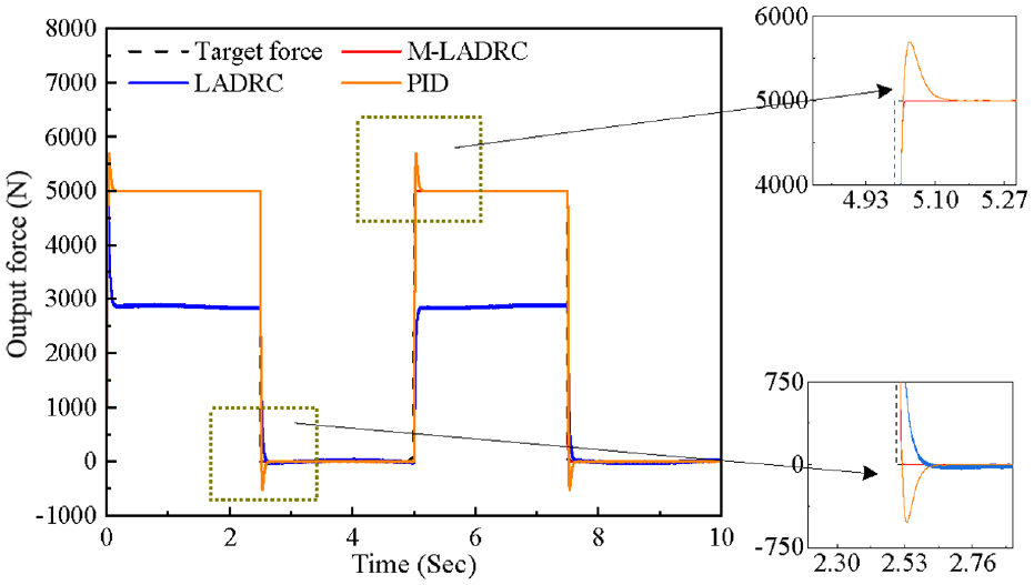
Force tracking curves under square wave signal.
Kalman filtering test
The centroid acceleration is observed by selecting an exciting pavement for testing, and the filtering performance of Kalman filtering algorithm is analyzed. In Figure 11, The actual measured values, real values, and Kalman filter observed values are compared. Figure 12 is a partial enlargement of Figure 9. It is not difficult to see that the measurement value of the sensor contains large noise, but the error value between the real value and the observer value is small after Kalman filtering. The real state information of the system is well estimated, which indicates that Kalman has a nice suppression effect on the sensor noise.
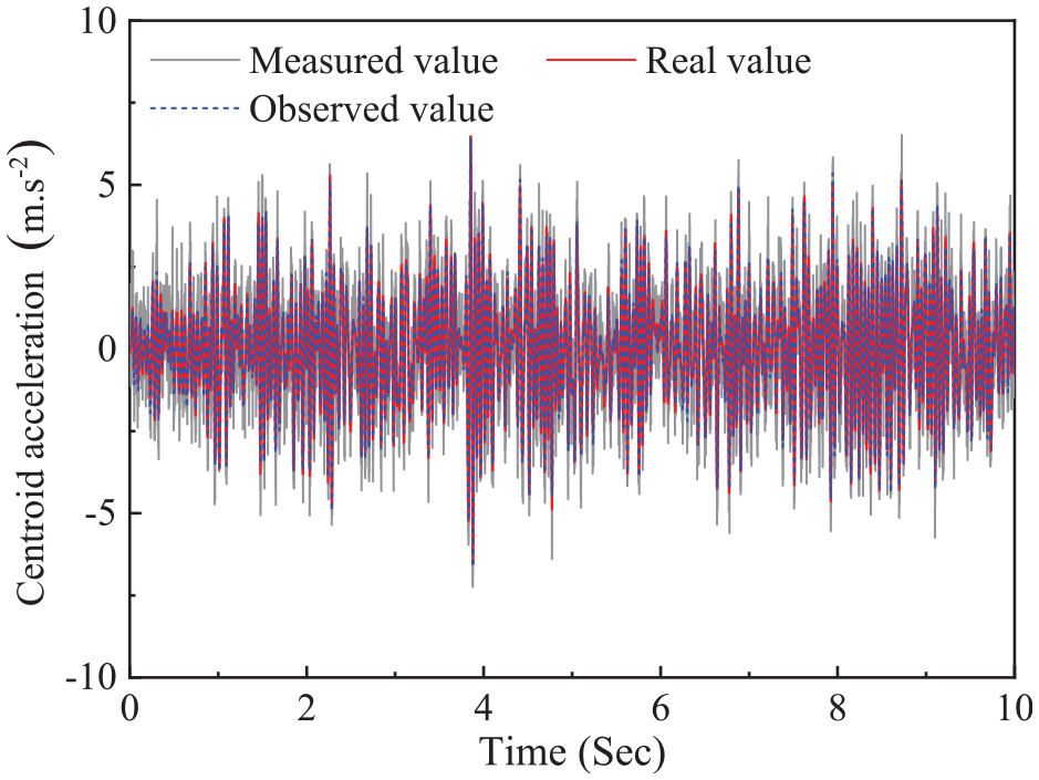
Kalman filtering effect comparison for centroid acceleration.
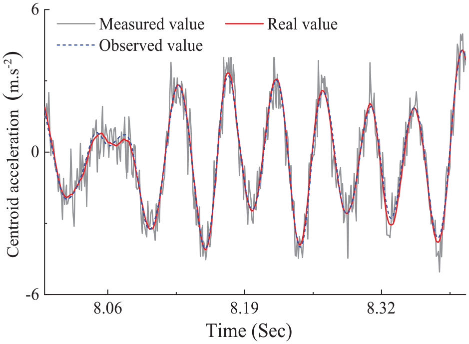
Local amplification for Figure 11.
Active suspension performance analysis
This paper has presented a collaborative control method based on LQR and M-LADRC. In order to evaluate the performance of this method, the proposed control scheme is implemented on a 1/4 of vehicle model. Trapezoidal road profile (Figure 13) and Grade C Road profile are respectively used for semi-physical simulation tests in this paper. Figure 14 illustrates the trapezoidal road profile input. When a vehicle crosses the trapezoidal road profile, the sprung mass acceleration response of trapezoidal pavement under semi-physical simulation active suspension, ideal active suspension, and passive suspension is shown in Figure 15. Besides, the acceleration response is shown in Figure 16 during a vehicle cross over Grade C Road profile.
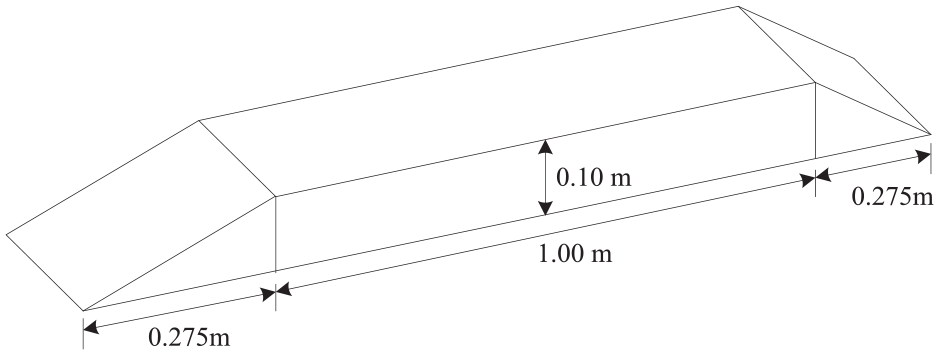
Trapezoidal road profile.
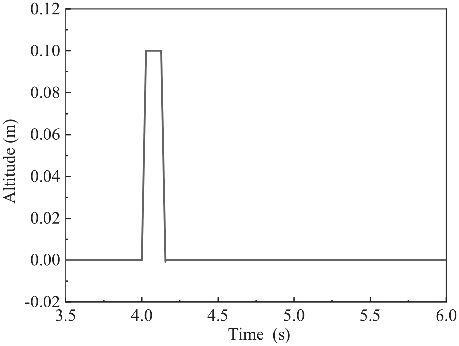
Trapezoidal road profile input.
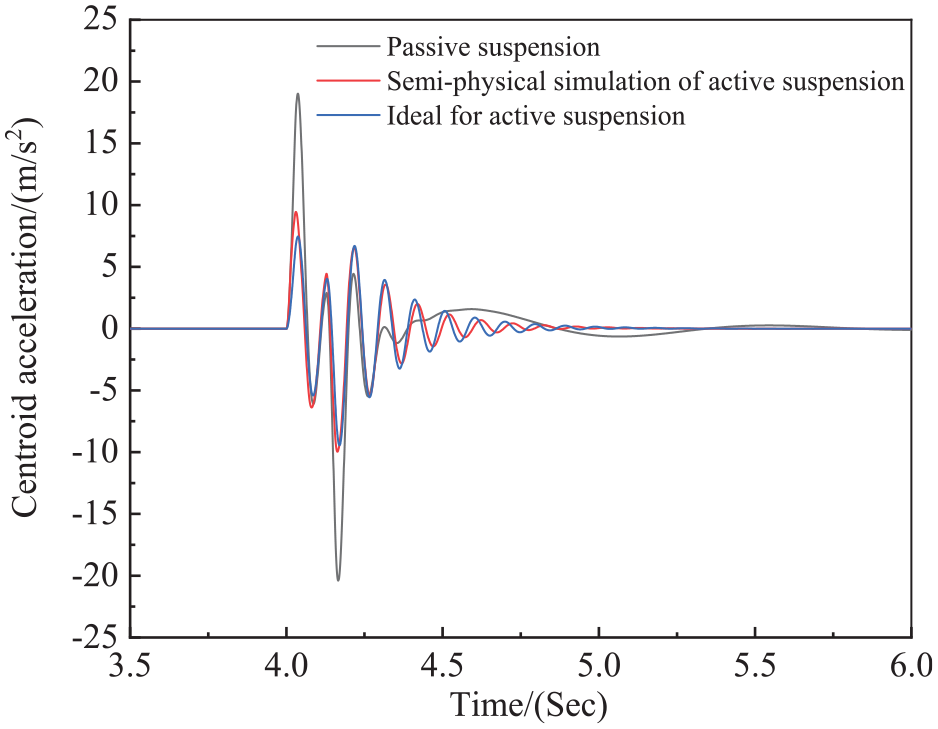
Response of sprung mass acceleration (Trapezoidal Road profile excitation).
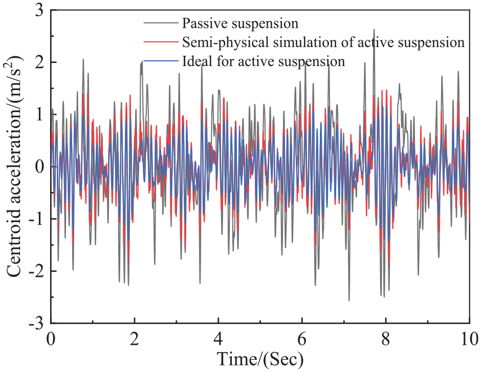
Response of sprung mass acceleration (Grade C road profile excitation).
Under the excitation of a Trapezoidal Road profile, tests were conducted using semi-physical simulation active suspension, ideal active suspension, and passive suspension. The test results show that the acceleration of sprung mass shows different degrees of oscillation, with the maximum oscillation’s amplitudes being 19.02
Discussion
In this study, the LADRC algorithm has been improved, resulting in the M-LADRC control algorithm. M-LADRC, LADRC, and PID control algorithms were used to track a target force with increasing frequency. The study found that as the target force frequency increased, the tracking performance gradually deteriorated. This phenomenon primarily occurs because the hydraulic active suspension system is a complex system with inherent inertia, characterized by high-order nonlinearity and a dynamic response involving multiple state variables. As the system frequency increases, phase lag becomes more pronounced, leading to increased tracking errors.
The active suspension system monitors vehicle vibrations in real-time using sensors and actively adjusts the suspension force through control algorithms to suppress vibrations within specific frequency ranges. Frequencies around 1 Hz are typically associated with the vehicle’s vertical vibration natural frequency, where traditional passive suspension systems often exhibit significant vibration peaks. However, by employing the hydraulic active suspension system, this study demonstrates a significant reduction in vibration energy at this frequency range, with the peak around 1 Hz being notably diminished.
To validate the effectiveness of the control algorithm, both ideal state simulations and Hardware-in-the-Loop (HIL) tests were conducted. As shown in Figure 17, the performance of ideal active suspension control is similar to that of HIL test active suspension control, indicating that the M-LADRC control algorithm exhibits good robustness and effectiveness in practical applications. This also indicates that the hydraulic active suspension system provides better suppression of low-frequency vibrations, not only enhancing ride comfort but also improving vehicle handling stability. The future research should proceed toward the Constructing a comprehensive vehicle dynamics model in the Adams environment and conducting joint simulations with Simulink represents. At the same time, it can be combined with deep reinforcement learning algorithms such as TD3 to further optimize the control effect. 50
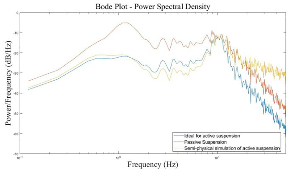
Power spectral density of sprung mass acceleration (Grade C Road profile excitation).
Conclusion
In this article, a collaborative control method based on LQR and M-LADRC is proposed to enhance the ride comfort and maintain a typical conflict between maintaining small wheel loads to ensure ride safety for hydraulic active suspension. To verify the actual control algorithm, a semi-physical simulation test method is proposed that is low-cost, safe, and reliable.
The hydraulic active suspension adopts a dual-loop control strategy, where the outer loop uses the LQR control algorithm to obtain optimal control forces, and the inner loop uses a M-LADRC control algorithm to track target forces. The M-LADRC controller takes into account system physical model information, reducing the controller design complexity. By constructing a collaborative controller and a LESO parameter set, the number of control parameters is reduced, which reduces the difficulty of estimating system disturbances. For the hydraulic servo system of active suspension, the semi-physical simulation shows that the comparisons of M-LADRC with LADRC and Classical PID have stronger anti-interference capabilities and can track the target force well.
Under different road disturbances, comparisons semi-physical simulation active suspension with ideal active suspension and passive suspension have been conducted. The improved performance of the suspension can be inferred from the proposed collaborative controller, which is more practical and more beneficial for the application of the achievements. Additionally, experimental verification of this collaborative control method will be an attractive future work, particularly suitable for active suspension control experiments and semi-active suspension control experiments for multi-axle vehicles. During the development process, there is no need to construct large-scale experiment equipment to verify the algorithm effectiveness, thereby eliminating any safety hazards and damaging expensive hardware risks.
Footnotes
Declaration of conflicting interests
The author(s) declared no potential conflicts of interest with respect to the research, authorship, and/or publication of this article.
Funding
The author(s) disclosed receipt of the following financial support for the research, authorship, and/or publication of this article: This work was partially supported by the General Program of Department of Science and Technology of Hunan Province (Grant Number 2024JJ5152), the Key Projects of Hunan Province Education Department of China (Grant Number 23A0362, 23A0376), the science and technology innovation Program of Hunan Province (2021RC4038).