
Abstract
Instead of using position sensor, a position measurement and output feedback tracking method is proposed based on pressure sensor for a class of hydraulic servo system. First, the desired accumulator pressure is calculated and obtained in an open-loop way according to the desired cylinder position. Then, the position tracking task can be indirectly realized by achieving the pressure control. As a result, only one pressure sensor is required instead of position sensor, which is different from almost all the traditional output feedback position controller of hydraulic system. For the closed-loop pressure tracking, a desired compensation method and an auxiliary variable-based state observer are integrated to form the nonlinear controller. The theoretical and numerical simulation results demonstrate that the presented controller can attain satisfactory pressure tracking performance.
Keywords
Introduction
Electro-hydraulic systems offer distinct advantages over conventional electric or mechanical drives, including high-power density and substantial force/torque output. 1 Because of these features, electro-hydraulic servo systems have been utilized in hydraulic robots, 2 hydraulic suspensions, 3 and various simulators. 4 To achieve optimal control performance, numerous advanced control strategies have been developed, such as adaptive robust control, 5 observer-based control, 6 and intelligent control. 7
Although many existing control methods can achieve expected tracking accuracy of hydraulic servo systems, they often require all the information of the system states. 8 To measure signals of all the system states, large installation space and extra cost are inevitable. Moreover, the measurement noise caused by theses sensors may deteriorate the tracking performance. Owing to the above deficiency, many output feedback controllers are developed. The prevailing configuration commonly consists of the extended state observer (ESO) and the back-stepping method. 9 In addition, many advanced control methods or functions, such as positive-increasing function, 10 adaptive control,11,12 valve dynamic compensation,13,14 model predictive control, 15 command filter,16–18 and disturbance observer,19–21 are incorporated with ESO to achieve satisfied performance. Alongside the aforementioned ESO-based state estimation approaches, there are other methods available for state estimation, such as fault-tolerant-based output feedback controller, 22 high gain observer,23,24 and fuzzy control. 25 However, despite the satisfactory performance of the aforementioned methods, most of them rely on position sensors instead of pressure sensors, even though position sensors are typically more expensive, bulkier, and harder to install than pressure sensors.
Therefore, if a technique could be developed to represent position using pressure signals and achieve output feedback, the benefits of output feedback control would be more pronounced. To achieve this, two issues need to be addressed: how to use pressure signals to represent cylinder position and how to achieve pressure control using only one pressure sensor based on the resulting system model.
For any system composed of hydraulic cylinders and accumulators, the direct relationship between accumulator pressure and position or velocity of hydraulic cylinder can always be found. In addition, some medium and large hydraulic systems are often equipped with a hydraulic accumulator to achieve many functions such as auxiliary driving and energy regeneration.26,27 In this study, the mathematical correlation between the cylinder’s position and the accumulator’s pressure is deduced based on a specific hydraulic system with accumulator. Subsequently, the tracking problem is transformed from position control to accumulator pressure control.
Although the use of position sensor can be avoided based on the aforementioned method, the task of achieving output feedback pressure control based on the asymmetric-hydraulic-cylinder-based system model is still an ongoing challenge that needs to be addressed. Up to now, several related methods have been explored in the literature, such as the singular value perturbation approach, 28 the equivalent model transformation method, 29 state equation reconstruction,30,31 and model linearization. 32 As a promising control method, the combination of model predictive control and neural networks may enable precise control through online learning.33,34 However, the aforementioned method cannot be applied to the proposed system. It is because the position control task is transformed into the pressure control, and these approaches are not suitable for the pressure signal-based state equation. To address this issue, an integrated approach incorporating a desired compensation method and a state observer is employed to solve the problem. Specially, the unknown third order state is estimated by an auxiliary variable-based observer. Furthermore, due to the unavailability of direct measurement or observation for the second-order state of the system, the corresponding desired value is used in the model compensation part both in the controller and the state observer. Through rigorous theoretical derivations and analysis, the system stability is confirmed. Besides, the resulting tracking accuracy of the proposed method, including pressure tracking and final position tracking, is validated by comparative results.
The primary contributions are listed as:
The position tracking objective is accomplished indirectly through the pressure control of the hydraulic accumulator.
An output feedback control method combining desired compensation and state observation method is proposed.
A position signal acquisition method based on pressure information is proposed for hydraulic systems with hydraulic accumulators.
Nonlinear model and control objective
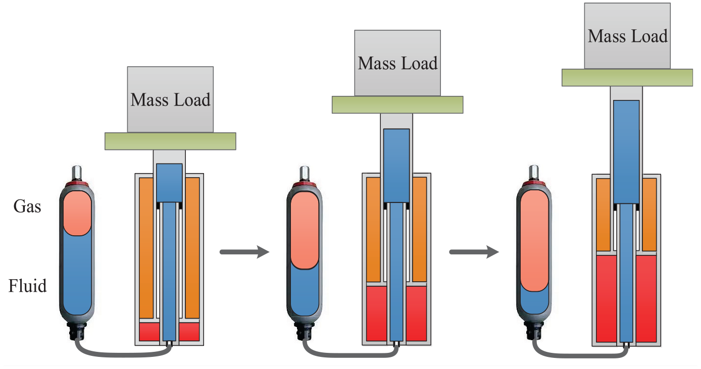
Figure 1(a) shows the simplified configuration of the system, while Figure 1(b) depicts the conventional two-chamber hydraulic actuator. In the proposed actuator, there are three operational chambers: the storage chamber, the piston chamber and rod chamber. The last two chambers of the system are connected with a proportional directional valve (PDV), which serves as the control element.
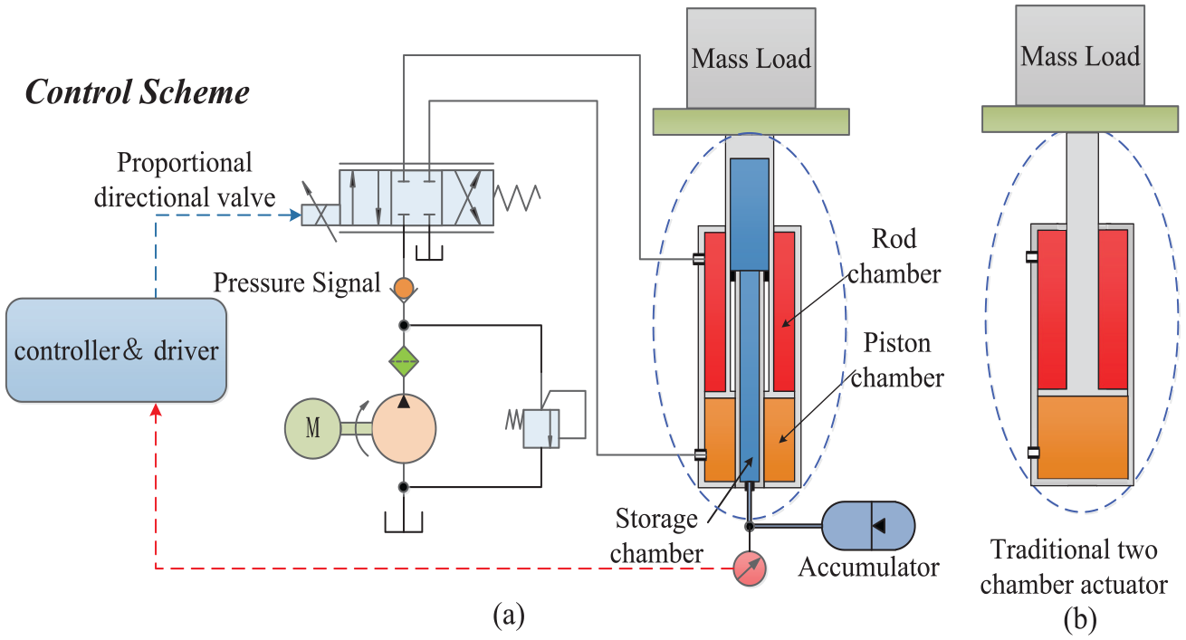
Simplified configuration of the proposed system (a) and the traditional two chamber hydraulic actuator (b).
Pressure model of the hydraulic accumulator
The first step is to deduce the pressure model for the accumulator. Assuming a scenario where the hydraulic cylinder undergoes rapid movement over a short duration, it is reasonable to consider the working process as an adiabatic process. According to Boyle’s theorem, one obtains

where
Based on the assumption that a positive flow rate for the hydraulic accumulator indicates energy release, while a negative flow rate indicates energy storage, the pressure dynamic is deduced as follows by referring to equation (1).
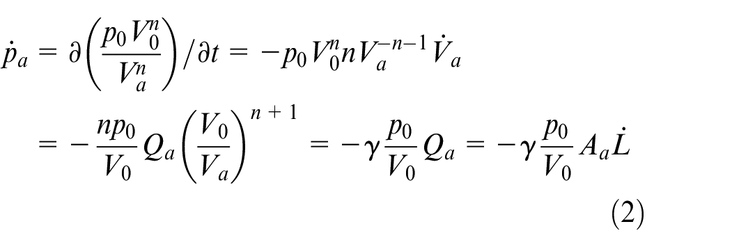
where
By combining equation (2), the time derivative of equation (2) is
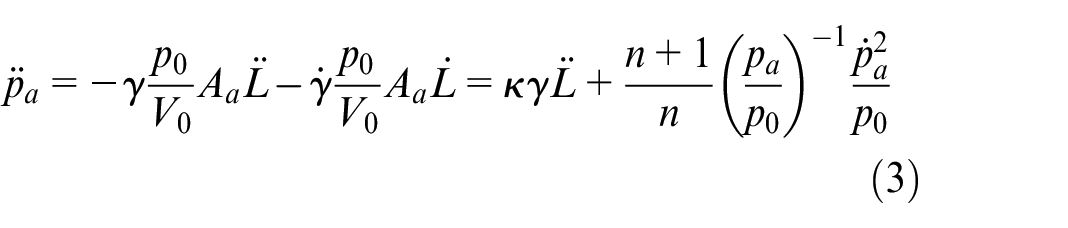
where
According to the expression of
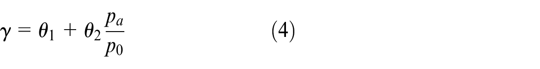
where
The relationship between
The relationship between
Based on equation (4) and consider the model uncertainties, equation (3) can be simplified as follows
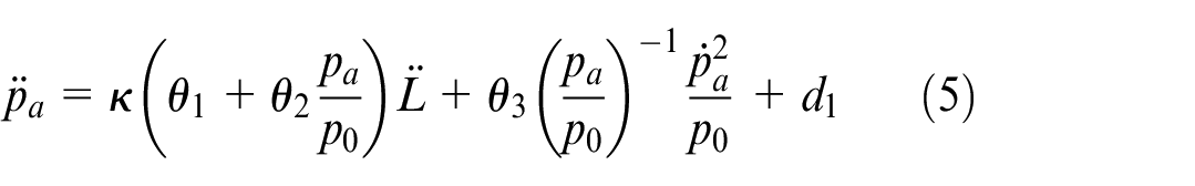
where
State equation of the system
The subsequent step is to obtain the complete state equation of the system by combining the pressure dynamic with the load balance equation and valve model. Considering that the friction force and damping force are relatively negligible compared with the load, the dynamic of the hydraulic piston is

where
The flow equation of the cylinder is expressed as
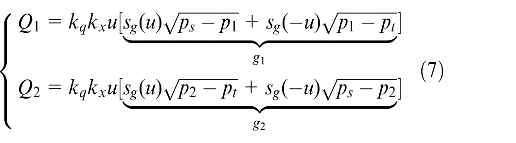
where
The pressure dynamics of the piston and rod chamber are given as follows by neglecting the leakage.
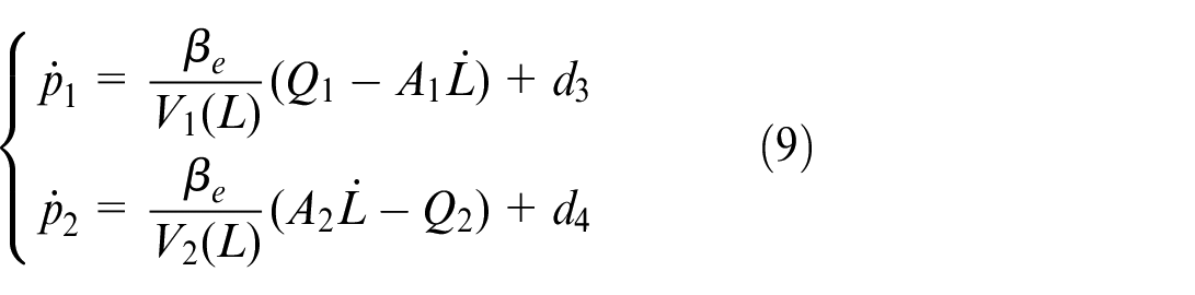
where
The state variables vector is

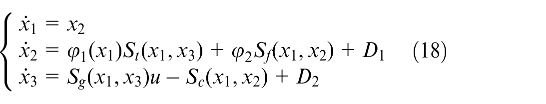
Based on equations (5)–(10), the pressure signal-based state equation is given as follows
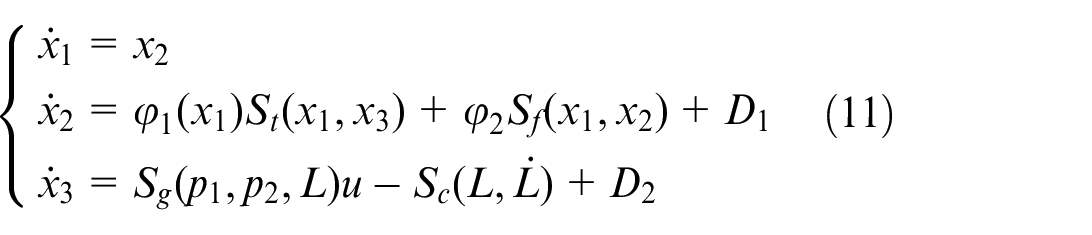
where
Transformation of the system model
From equation (11), one can find that the cylinder position is in the third state equation, which is unknown and is not represented by state variables. Therefore, the model should be transformed, thereby facilitating the subsequent derivation.
Based on equation (1), one can obtain
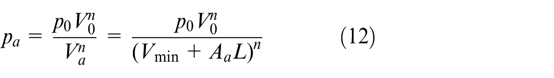
where
Based on equation (12), the relationship between the position of the hydraulic cylinder and the pressure of the hydraulic accumulator can be given as.
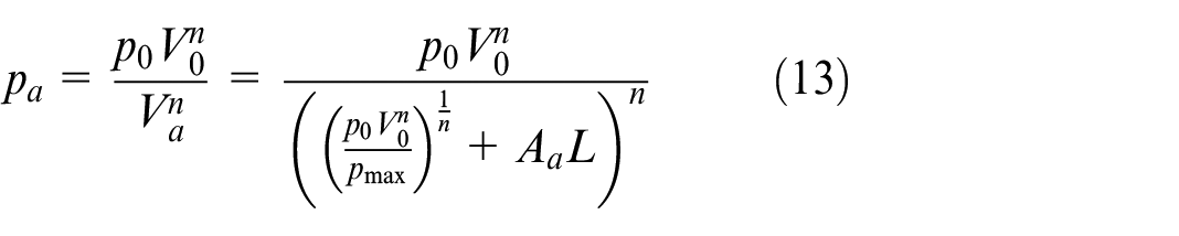
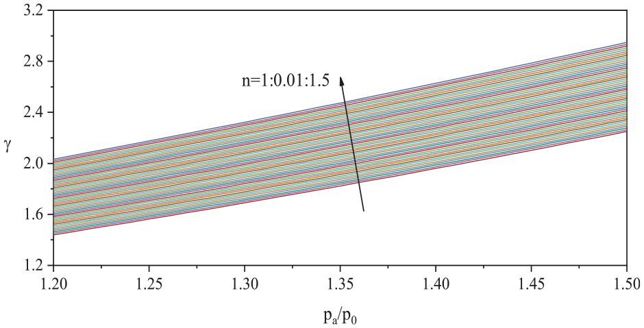
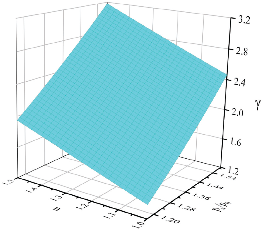
From equation (13) and Figure 4, the position of the hydraulic cylinder is directly related to the pressure of the hydraulic accumulator once the parameters are determined.
The relationship between
Based on equation (2), equation (13) and noting the definition of the state variables, it can be inferred that
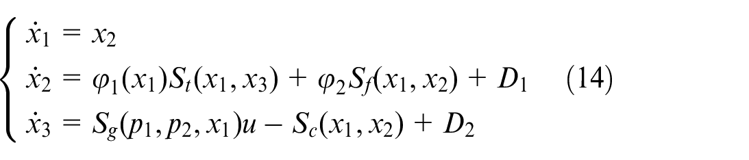
It can be seen that unmeasured two chamber pressures are still in the third state equation of equation (14). Then, the relationship between two chamber pressures and state variables should be deduced.
By neglecting oil compression, leakage, lumped uncertainties and assuming the tank pressure is zero, the following equations can be obtained from equations (7) and (9).
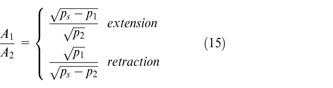
Because

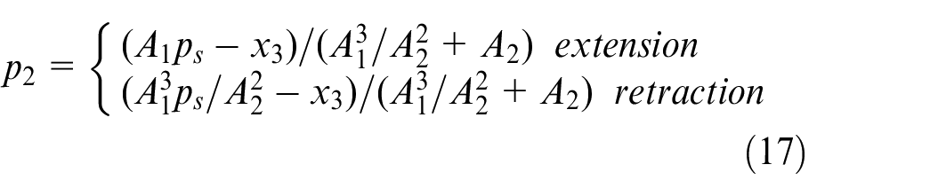
Therefore, equation (14) is reconstructed as
The modeling error caused by approximate estimation of pressure can be regarded as a part of

Where
Control objective and scheme
The equations (11) and (18) are state equations based on accumulator pressure. To achieve control of hydraulic cylinder position, it is necessary to establish a numerical relationship between the accumulator pressure and the cylinder position. Fortunately, it has been done by equation (13). Therefore, the desired hydraulic cylinder position can be brought into equation (13) to obtain the corresponding expected accumulator pressure. The polytropic index in equation (13) remains uncertain, playing a pivotal role in directly setting the target pressure and, in turn, indirectly influencing the attainable precision. Importantly, the determination of this index is not incorporated within the closed-loop pressure tracking system. As such, the choice of the polytropic index constitutes an open-loop aspect, resulting in a combined control approach that integrates open-loop parameter selection with closed-loop pressure control, as illustrated in Figure 5.
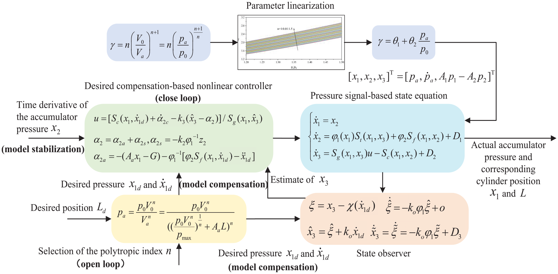
Schematic diagram of the proposed method.
The control task is concluded as: the expected pressure of the hydraulic accumulator
Closed-loop pressure control
From equation (18), it is evident that the conventional state observer, such as ESO, cannot be applied to the system. Therefore, an auxiliary variable-based observer is only used to obtain the estimate of the third state variable, and the time derivative of the accumulator pressure is regarded as the value of the second state variable. However, this will inevitably bring about measurement noise and affect achievable control performance. To mitigate the impact of measurement noise, the observer and controller design process incorporate the desired compensation method.
35
Specially, the desired value of
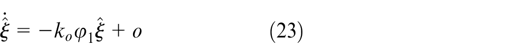
Design of the state observer
An auxiliary variable is defined as 36

where
In this equation, the desired value of
Based on equations (18) and (20), the dynamic of the auxiliary variables is

It can be seen from the above equation that the unmeasured signal
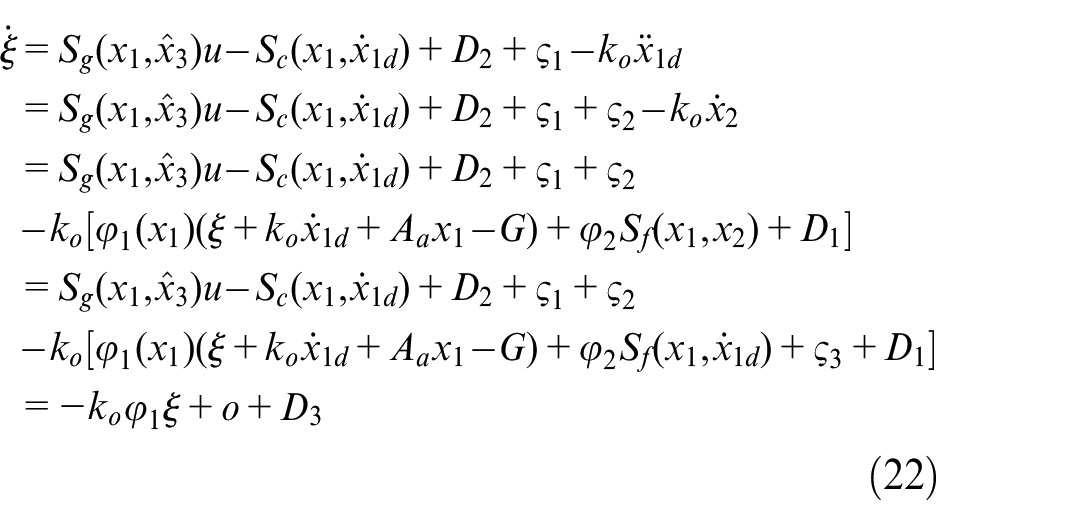
where

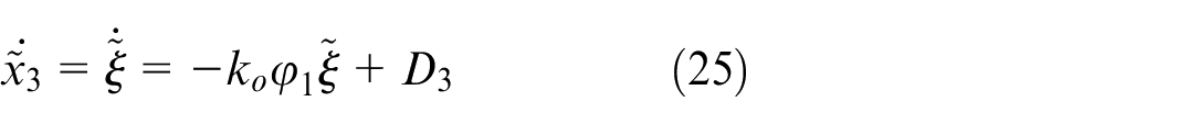
The dynamic of
The estimate of

Based on equations (20) and (24), the estimation error of
A Lyapunov function is selected as
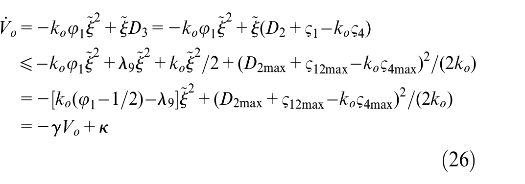
where
Based on equation (26), it can be claimed that
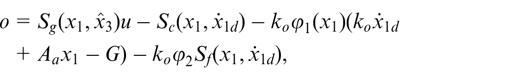
Desired compensation-based nonlinear controller
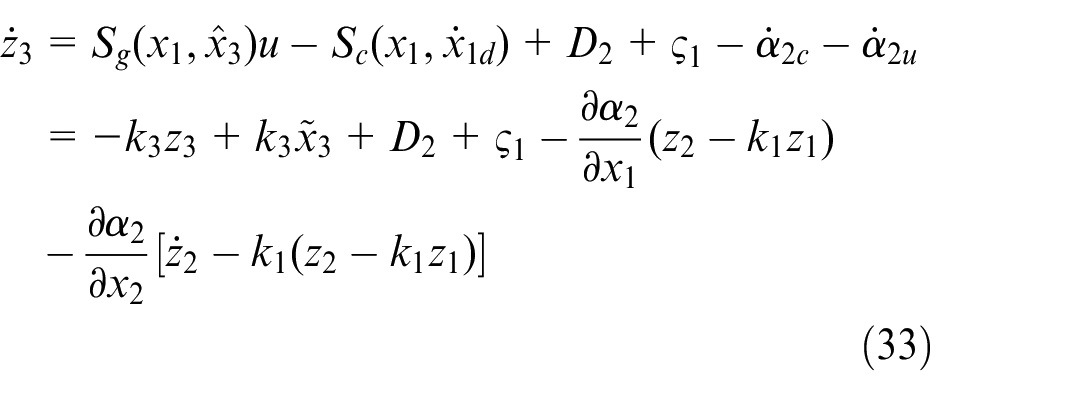
Based on the above analysis, the estimate of the third state variable, namely
where
By substituting the unmeasured signal
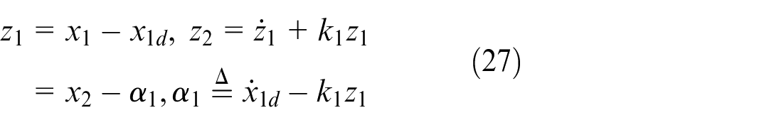
The virtual control input
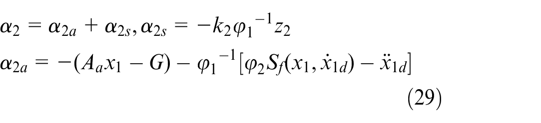
Where
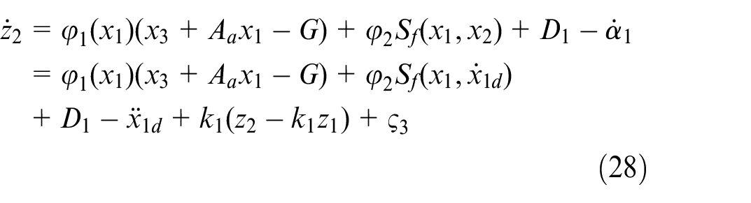
Substituting equation (29) into equation (28), one obtains

where
In this equation, the third state variable is replaced by its corresponding estimate according to the result of equation (24), thereby canceling the measurement of the third state variable.
To avoid using pressure differentiation,
where
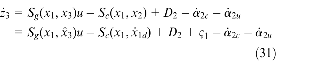
The resulting control law can be defined as

where
Substituting equation (32) into equation (31), one obtains
Main results
According to the mean value theorem and equations (19), (27), (30), and Remark 2, the following inequality can be obtained.


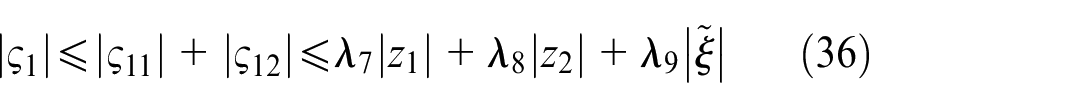
where
The Lyapunov function is defined as
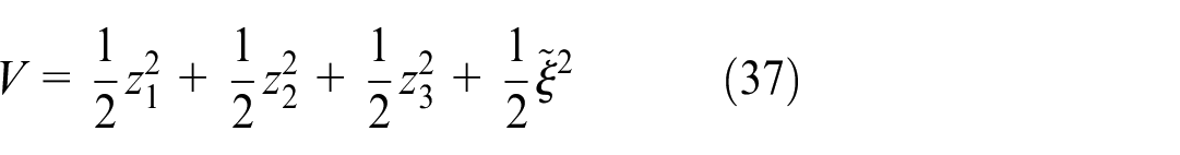
In addition, it can be inferred that
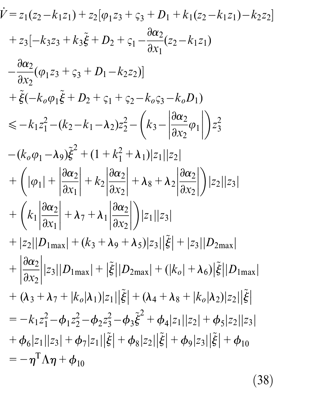
where

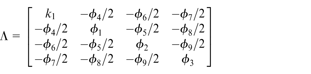
When the matrix
A. When
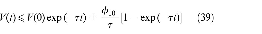
where
B. When

It can be inferred from equation (40) and Barbalat’s lemma that asymptotic tracking can be achieved, that is,
Comparative results
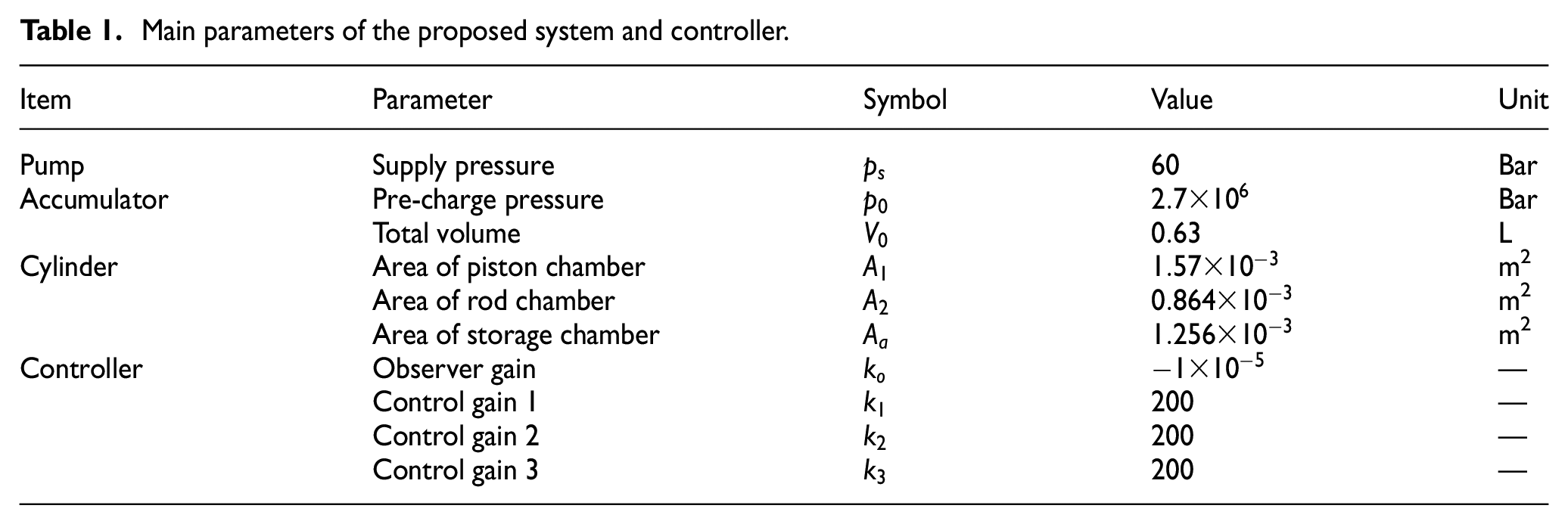
For verifying the effectiveness of the proposed system, comparative simulations have been conducted. The main parameters of the proposed system and controller are given in Table 1.
Main parameters of the proposed system and controller.
The following three controllers are used for comparison.
Three performance indexes are used to evaluate the performance of each control algorithm, that is, the maximum absolute value of tracking errors
The tracking performance of the proposed controller is first tested for a smooth sinusoidal-like motion trajectory
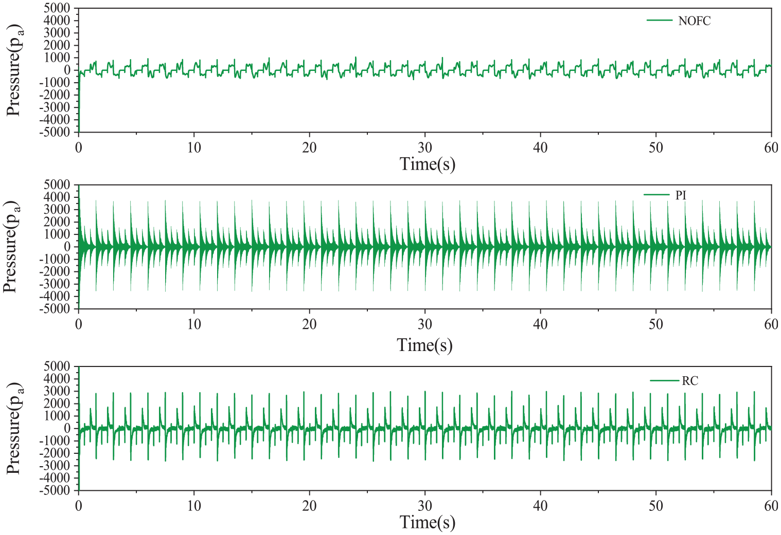
Figure 6 shows that the NOFC controller consistently maintains lower tracking errors compared to the PI and RC controllers throughout the sinusoidal trajectory. This indicates the robustness of the NOFC controller in handling dynamic variations and its superior ability to maintain stability under fluctuating conditions. The PI controller, while simple and easy to implement, lacks the sophistication needed for precise model-based compensation, which becomes evident in scenarios with significant inertia. The main reasons lies in several aspects. The first is the response speed. Although the proportion term (P term) in the PI controller can quickly adjust the control output based on the size of the error signal, the response speed of the system may be limited when dealing with large inertial loads. This means that even if the PI controller attempts to accelerate the system response by increasing the control output, the inertia of the load may hinder this rapid response. Additionally, even if the effect of the proportional term can make the system respond faster, it may also cause overshoot of the system. For high inertia loads, this overshoot and oscillation phenomenon may be more pronounced. Moreover, the performance of the PI controller largely depends on the setting of its parameters. However, for large inertial loads, finding a suitable set of parameters may be challenging. Inappropriate parameter settings may lead to system instability or performance degradation. Due to the existence of model compensation terms, NOFC and RC can offset the adverse effects by introducing a compensation term related to inertia, reduce the dynamic error of the system. The RC controller, despite being robust, fails to match the NOFC’s performance due to the absence of desired compensation. This is mainly due to the measurement noise contained in the pressure dynamic of the hydraulic accumulator, which affects the final tracking accuracy.
Tracking errors of the three controllers in test 1.
Figure 7 further validates the superior performance of the NOFC controller by comparing key performance indices such as maximum absolute tracking error, average tracking error, and standard deviation. The NOFC controller not only shows lower values across all indices but also demonstrates more consistent and reliable performance. This consistency is crucial for applications requiring high precision and reliability. The PI controller, with its higher variability, highlights its limitations in maintaining stable performance under varying conditions. The RC controller, while better than PI in some aspects, still lags behind NOFC due to its lack of desired compensation. Moreover, as the trajectory period becomes shorter, the tracking error of both controllers increases, but the tracking errors of PI and RC are always greater than that of NOFC.
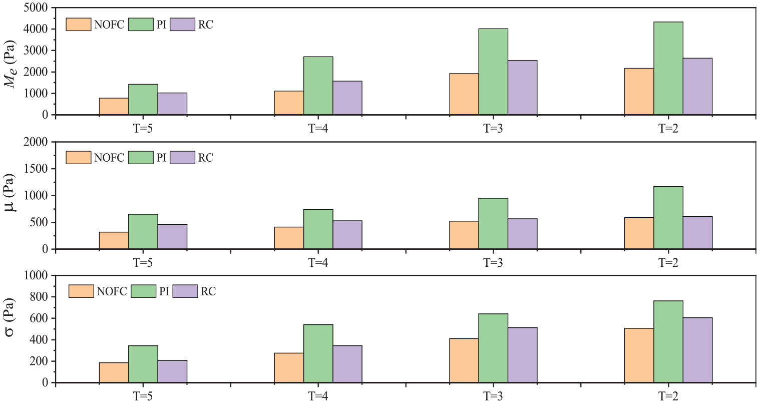
Comparison of performance indices in test 1.
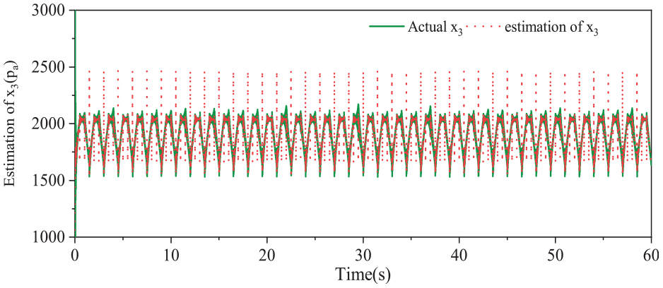
The estimation result is demonstrated in Figure 8. It can be seen that the proposed observer is able to obtain accurate estimation result of the state variable. By using the observer, output feedback can be achieved. The accurate state estimation is critical for the success of the NOFC controller. The observer’s capability to provide precise state feedback ensures that the NOFC controller can perform model-based compensation effectively. This capability is essential for maintaining control accuracy and stability, especially in systems with inherent uncertainties and dynamic changes.
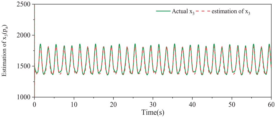
Estimation result in test 1.
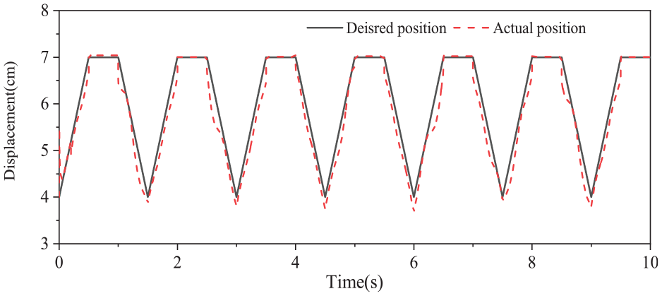
The position tracking result is shown in Figure 9. As discussed above, the position tracking accuracy can be adjusted by choosing the nominal value of the polytropic index carefully. The ability to indirectly track the position through precise pressure control highlights the controller’s sophistication in handling multi-variable control tasks. This indirect approach, while complex, allows for more flexible and robust control strategies, particularly useful in systems where direct position tracking might be challenging or impractical.
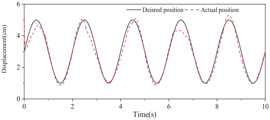
Position tracking result in test 1.
To further validate the applicability of the proposed method, a sawtooth-like motion trajectory is used as the desired position trajectory, which can be seen in Figure 13 (In this case, the polytropic index is set as 1.31 and the load condition is the same as test 1). Figures 10 and 11 demonstrate the tracking errors and performance indices respectively. These two figures provide a clear comparison of controller performances under more challenging conditions due to a faster motion trajectory. It is evident that the accuracy of the proposed NOFC is superior than that of the PI and RC controllers, as indicated by the provided performance indices. The maximum tracking error consistently occurs at the turning point of the trajectory. The sawtooth trajectory introduces sharp changes that test the responsiveness and robustness of each controller. The NOFC controller’s superior performance in handling these changes, along with its resilience to disturbances, underscores its practical applicability in such severe working scenarios.
Tracking errors of the three controllers in test 2.
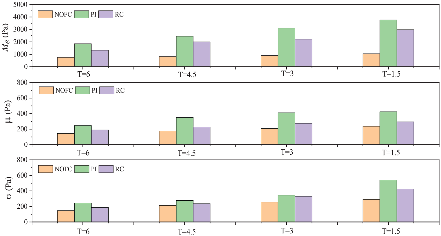
Comparison of performance indices in test 2.
The estimation results of the state variables are depicted in Figure 12, showcasing the acceptable estimation capability of the proposed observer even under significant disturbances. The position tracking results are illustrated in Figure 13, demonstrating that the proposed method can indirectly obtain the position of the cylinder by utilizing the pressure signal of the hydraulic accumulator. Notably, it should be mentioned that the stroke of the hydraulic cylinder is 7 cm. Therefore, the straight section of the curve seems to exhibit better tracking performance. The consistent performance of the NOFC controller, even under large disturbances, as shown in Figures 12 and 13, highlights its robustness. The observer’s accurate state estimation ensures that the controller can adapt to disturbances effectively, maintaining control accuracy. The effective tracking of the hydraulic cylinder position, despite the short stroke, demonstrates the practical feasibility of using pressure signals for position control, offering a versatile solution for various hydraulic systems.
Estimation result in test 2.
Position tracking result in test 2.
Conclusions
Hydraulic servo control often adopts output feedback control to save costs and overcome the influence of sensor noise as much as possible. This method usually only requires one displacement sensor to achieve the control goal in position control. However, compared with pressure sensors, displacement sensors have higher costs and installation difficulties. Therefore, this paper proposes a position output feedback control method based on pressure sensor to further highlight the advantages of output feedback control. Therefore, the method proposed in this paper can provide a new solution for the industrial application of hydraulic servo systems. Additionally, a nonlinear output feedback pressure controller is developed, incorporating a state observer and desired compensation method. The system stability is guaranteed using the Lyapunov method, demonstrating that the proposed controller achieves the desired tracking performance in the presence of time-varying uncertainties and asymptotic tracking performance in their absence.
However, the proposed method also has certain limitations in practical applications. On the one hand, it is necessary to analyze or establish the relationship between the displacement of hydraulic cylinder and the accumulator pressure in advance, and the numerical relationship varies for different hydraulic systems. On the other hand, the polytropic index is not a constant in practical applications, and the accuracy of this parameter will directly affect the accuracy of displacement estimation. Therefore, how to establish a universal relationship between displacement and pressure and obtain accurate values of the polytropic index through online parameter estimation is the future research direction and challenge of this method.
Footnotes
Declaration of conflicting interests
The author(s) declared no potential conflicts of interest with respect to the research, authorship, and/or publication of this article.
Funding
The author(s) disclosed receipt of the following financial support for the research, authorship, and/or publication of this article: This work is supported by the basic science research projects of higher education institutions in Jiangsu Province (natural science) [Grant No. 23KJB460013]; [Grant No. 23KJB460014]; Basic research plan of Xuzhou city [Grant No. KC23005]; Innovation and entrepreneurship training program for college students in Jiangsu Province [Grant No. 202310320142Y].
Data availability statement
Data sharing not applicable to this article as no datasets were generated or analyzed during the current study.