
Abstract
Servo dynamic stiffness is a pivotal index in characterizing the rejecting performance for the exogenous periodic disturbances of the repetitive learning control system. In this paper, the mathematical modeling of the servo dynamic stiffness for the well-designed repetitive learning control system with multiple-periodic signals is studied by the frequency analysis method. To analysis the complex form of the servo dynamic stiffness, the magnitudes of the direct (real part) and quadrature (imaginary part) servo dynamic stiffness at harmonics of the disturbance are discussed based on the parameters of the repetitive learning controller. An illustrated example of the two linear servomotors with the mechanical coupling is given in this study. Computer simulation are presented to illustrate the effect of the proposed measurement method of the servo dynamic stiffness for the multiple-periodic repetitive learning control system. The proposed servo dynamic stiffness modeling can be used to accurate design the parameters of the repetitive learning control system, such that the batter control performance of the repetitive learning control system at most of the harmonics of the multi-periodic input signal can be achieved.
Introduction
The property of the disturbance rejection is commonly referred to as servo dynamic stiffness (SDS), and it plays a vital role in characterizing the disturbance rejection response of a control system. The SDS quantifies the amount of input force needed to induce a unit output deviation, making it a crucial metric for assessing the system’s effectiveness in handling external disturbances. Ensuring a high SDS is essential in control systems to meet the necessary level of the disturbance rejection capability. Conversely, the capability to reject lower frequency disturbances is often associated with what is known as static stiffness. Thus, achieving superior control system performance requires a thoughtful consideration of both the SDS and static stiffness aspects. In real-world applications, various engineering systems, including robotics, manufacturing processes, and aerospace technologies, heavily rely on effective disturbance rejection to maintain accurate and reliable performance. To achieve required performance, engineers must improve the SDS and static stiffness when designing control systems. Enhancing the SDS becomes a critical factor in control system design, resulting in more robust and high-performance systems that excel in handling complex dynamic disturbances. From the related literatures, the SDS is often discussed for the analysis the control performance of the control system and vibration characteristic of the mechanisms. A high-static–low-dynamic stiffness isolator with tunable electromagnetic mechanism can be found in Sun et al. 1 In Zhongbin et al., 2 a SDS of a coupled two-spans for harmonic motion is presented. In Jalaleddini et al., 3 the identification of a joint dynamic stiffness with a structural decomposition subspace method for decomposition of the joint torque is given. In Banerjee et al., 4 the modeling of a SDS for a three-layered sandwich beam of unequal thicknesses is proposed. In Banerjee et al., 5 using the dynamic stiffness method, the free bending vibration of rotating tapered beams is analyzed. In Zhou and Liu, 6 the SDS is used to analyze the control performance of a tunable vibration isolator. In Lu et al., 7 a modeling of SDS of electromagnetic linear actuator is given. In Ding et al., 8 to improve the SDS, the acceleration feedback control for fast tool servo machines is given. In Bai and Quan, 9 a novel method to improve SDS of electro-hydraulic servo systems is proposed. In Pandilov and Dukovski, 10 a static and dynamic stiffness of CNC machine tool servo drives with disturbance forces is given. In Niu et al., 11 the three-way SDS of the bogie suspension system is given. In Sivrioglu and Basaran, 12 using a proposed dynamic stiffness method, a model of a superconductor magnetic bearing system is given. In Bao et al., 13 a mathematical model of the SDS for the proposed electro-hydraulic servo-valve is given. In Zhang et al., 14 the comparison study of two SDS for linear motor is proposed. In Shen and Tsai, 15 an H-infinite loop shaping with advanced PDFF controller is used to enhance the SDS of the control system. In Yen and Chang, 16 the performance robustness and SDS analysis for a machine tool control system with servo control algorithms is proposed. In Lv et al., 17 the distributed parameters modeling for the dynamic stiffness of a spring tube in servo valves is given. In Yao et al., 18 the SDS of the repetitive control system was brief proposed and applied to advanced metrology analyzer. In Yao, 19 to improve SDS, a new method for synthesizing repetitive controllers is proposed. A simple analysis of the SDS is given.
In this paper, the mathematical modeling of the SDS for the well-designed repetitive learning control (RLC) system with multiple-periodic signals is studied. To analysis the complex form of the SDS, the direct (i.e. real part of SDS) and quadrature (i.e. imaginary part of SDS) SDS at harmonics of the disturbance are defined and the theoretical relationship of the SDS and the controller’s parameters of the RCL system are discussed. An illustrated example of the two linear servomotors with the mechanical coupling is used to illustrate the effect of the proposed measurement method of the SDS for the RLC system.
Servo dynamic stiffness of control system
As shown in Figure 1, a simple closed-loop control system is given, where
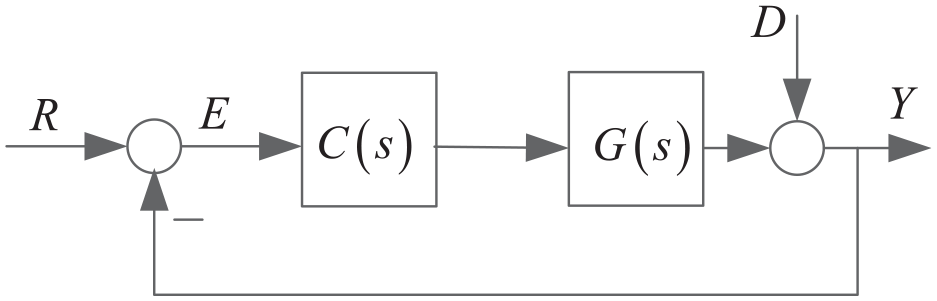
Closed-loop control system.
With
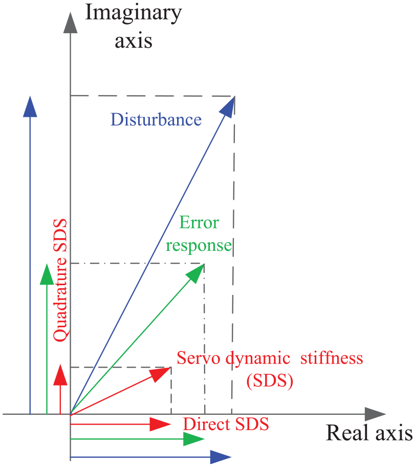
Plots of the complex form of SDS, the disturbance, and the error response of Figure 1.
A simple example is used to simulate for the SDS analysis in Figure 3, where
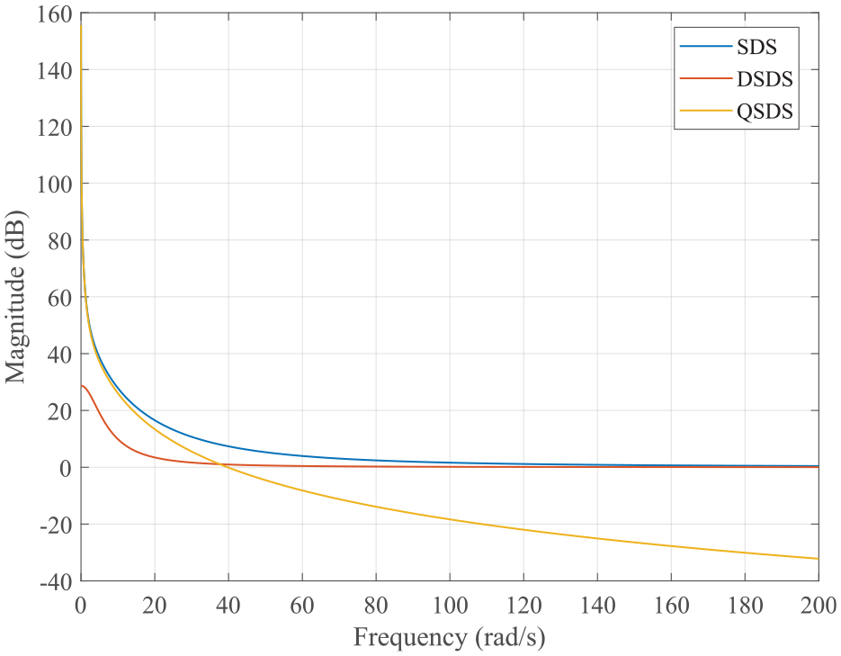
Magnitude plots of SDS, DSDS, and QSDS of the given example.
Servo dynamic stiffness analysis of repetitive learning control system
It is well known that the RLC system can be used to reject periodic disturbances in practical applications.
20
Based on the internal model principle, the RLC system can achieve well rejection performance if the generator for all frequency modes of the periodic signal is included in the control loop.
20
A periodic disturbance with period of
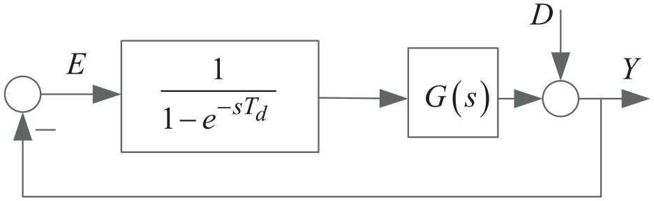
Block diagram of RLC system with the internal model of the periodic disturbance.
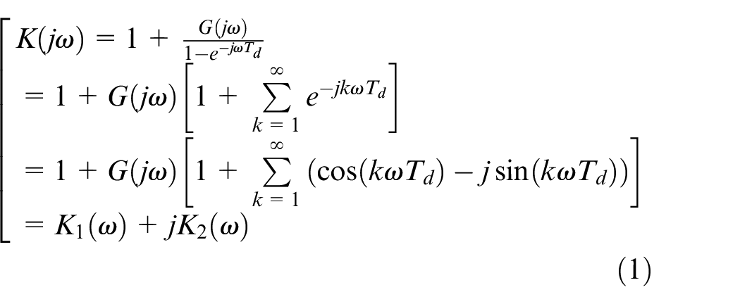
For the periodic disturbances rejection performance of the RLC system, the SDS is an important index; therefore, to enhance the SDS of the RLC system can be used to improve the rejection performance. SDS refers to the ability of the system to resist the output deviation caused by external force under the action of the control system. The complex form of SDS in Figure 4 can be given as (1), where
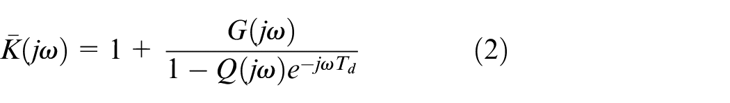
The non-stability of the RLC system in Figure 4 with only internal model of the periodic disturbance can be found. Therefore, to improve the stability of Figure 4, a low-pass filter
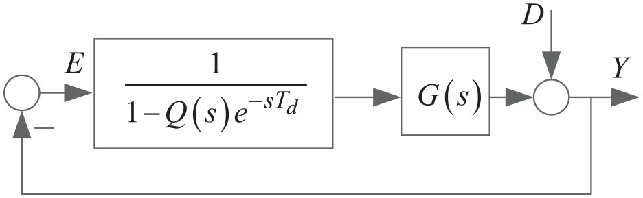
Block diagram of modified RLC system with
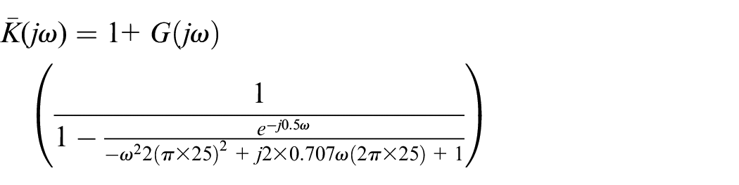
Based on
where
and
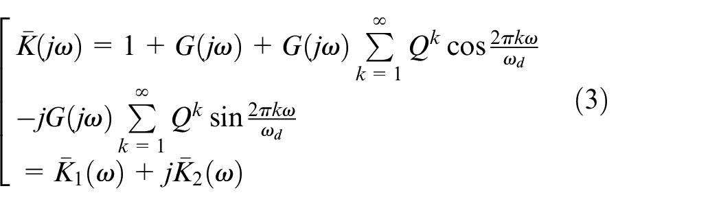
Then the DSDS and QSDS of Figure 5 for
and
The DSDS and QSDS of Figure 5 at
DSDS and QSDS of Figure 3 at
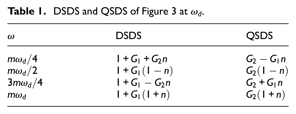
From Table 1, we can find that for
For the RLC system with multiple periodic disturbance, as shown in Figure 6, the disturbance
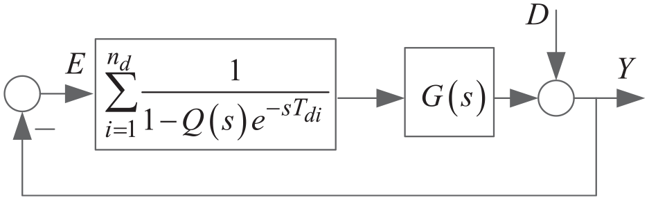
Block diagram of modified RLC system with multiple periodic disturbance.
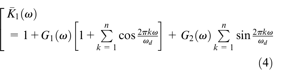
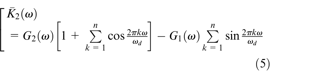
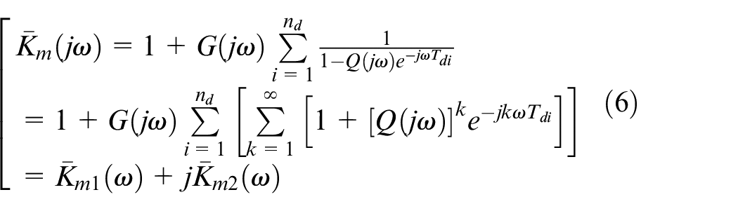
The DSDS and QSDS of Figure 6 for
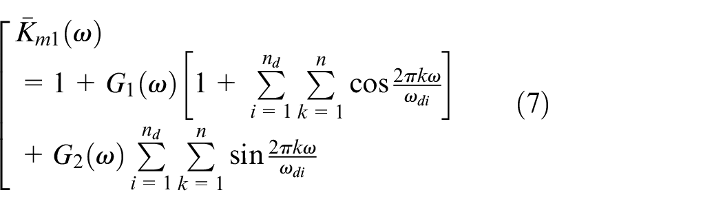
and
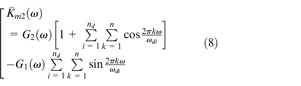
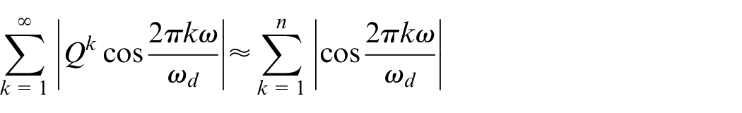
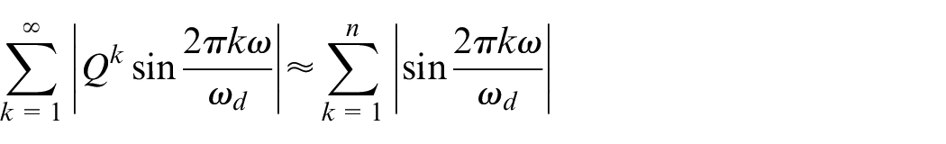
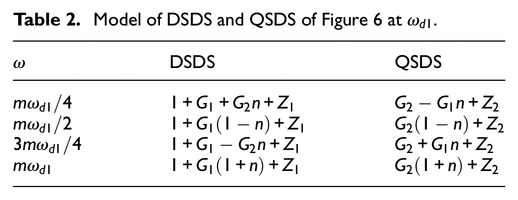
As
Model of DSDS and QSDS of Figure 6 at
Servo dynamic stiffness is a pivotal index in characterizing the rejecting performance for the exogenous periodic disturbances of the RLC system. Therefore, the theoretical relationship of the SDS and the controller’s parameters of the RCL system is given in this paper. The proposed SDS modeling can be used to accurate design the parameters of
An illustrated example
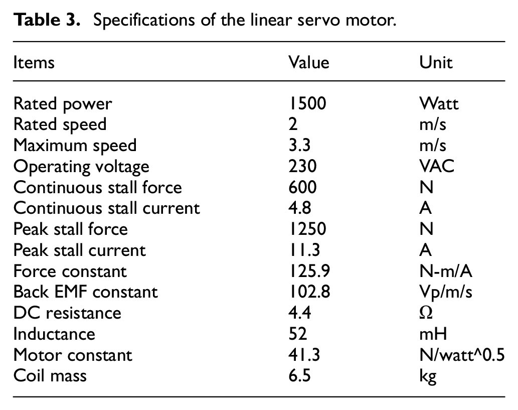
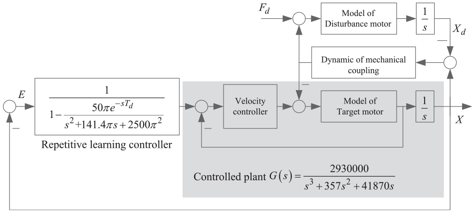
Figure 7 is the illustrated example of the two parallel linear motors with the mechanical coupling in this study, where the linear motor is given as the target plant and the other one is a disturbance generator. Table 3 shows the specifications of the linear servo motor. The velocity of the motor can be estimated or measured by linear encoder. The two motors are driven in the thrust control mode (i.e. the motor’s operation of the thrust command to the velocity output) as shown in Figure 8. As indicated in Figure 8 the controller motor is mechanically coupled to the disturbance motor, its dynamics is affected by the mechanics of the coupled system, that is, the mechanical coupling and the other motor. The velocity controllers are pre-designed to stabilize the control system of the target motor for the required performance. Note that the controlled plant
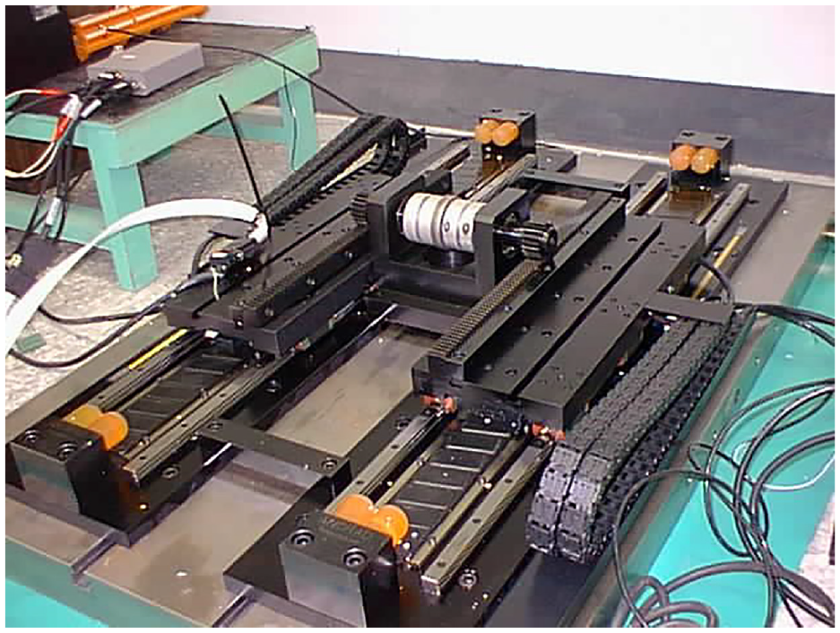
Illustrated example of the twin linear servomotors with the mechanical coupling.
Specifications of the linear servo motor.
Proposed RLC system.
From the design method of the RLC,
20
the designed low-pass filer
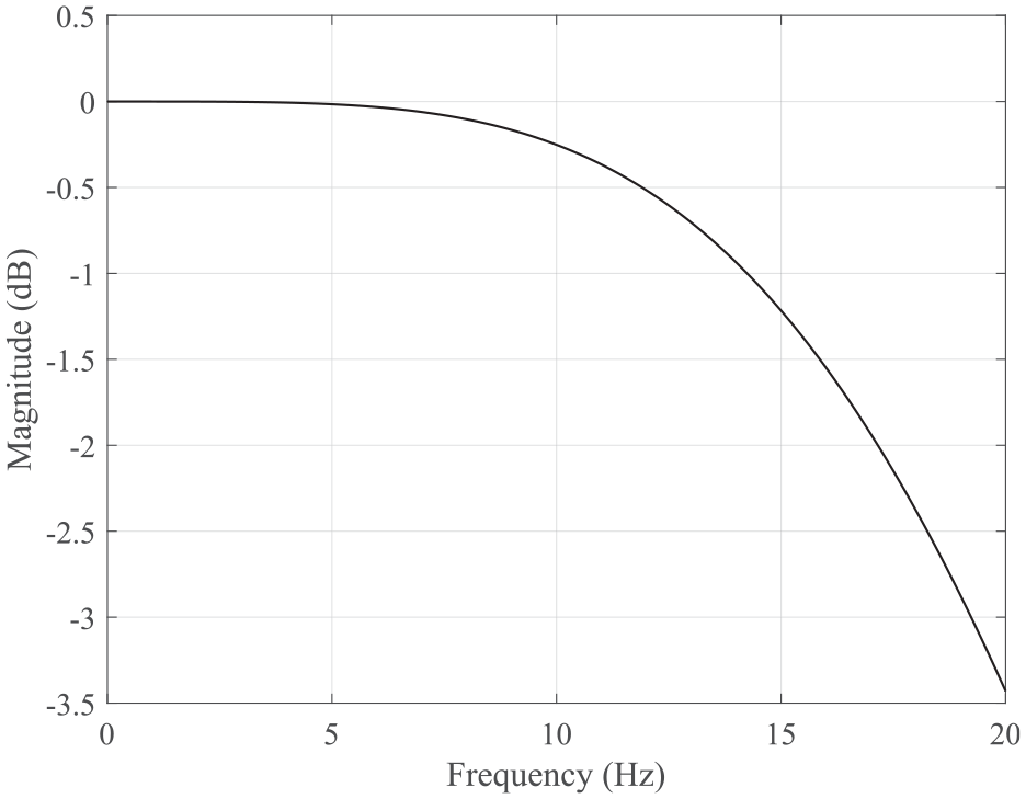
Magnitude plot of
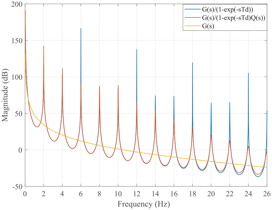
Plots of
Considering the single periodic disturbance with a period of
Under the single periodic disturbance with a period
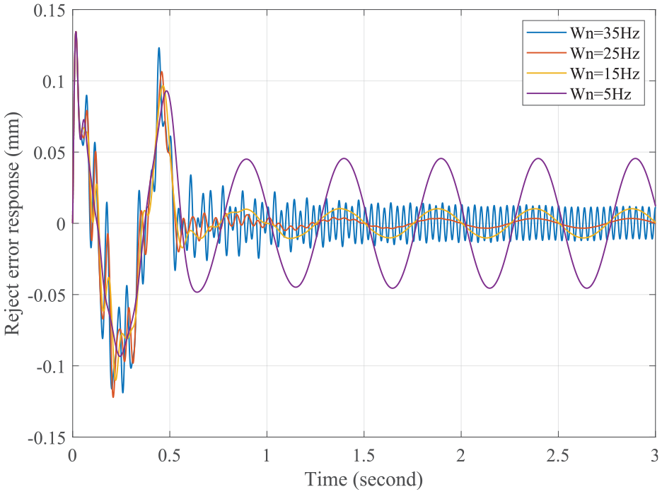
Reject error responses with
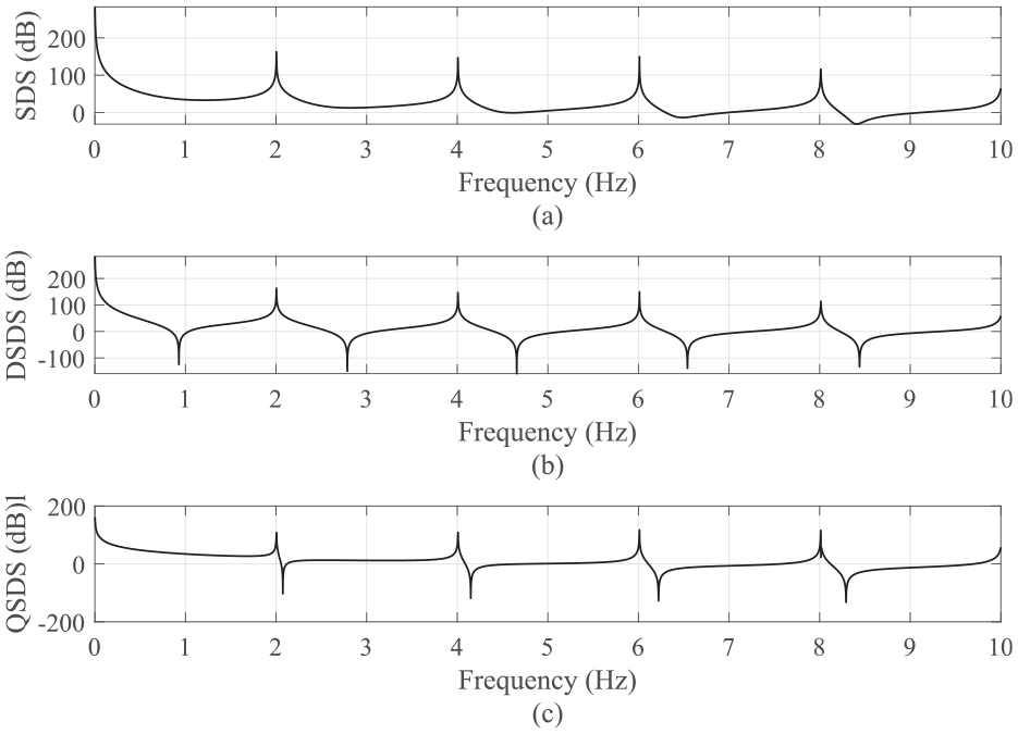
Magnitude plots of (a) SDS, (b) DSDS, and (c) QSDS under the single periodic disturbance with
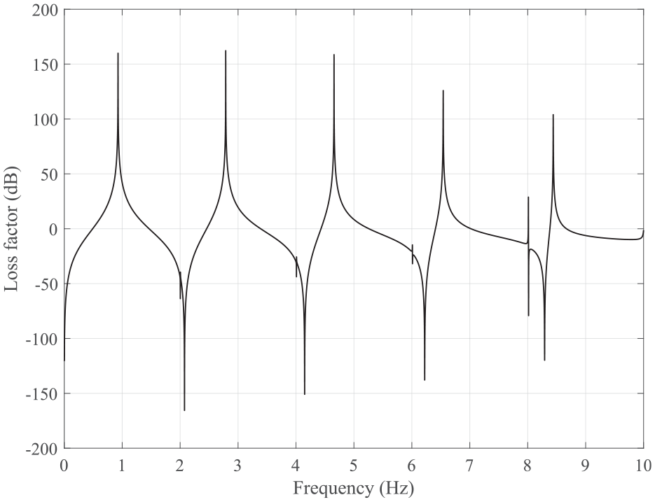
Loss factor under the single periodic disturbance with
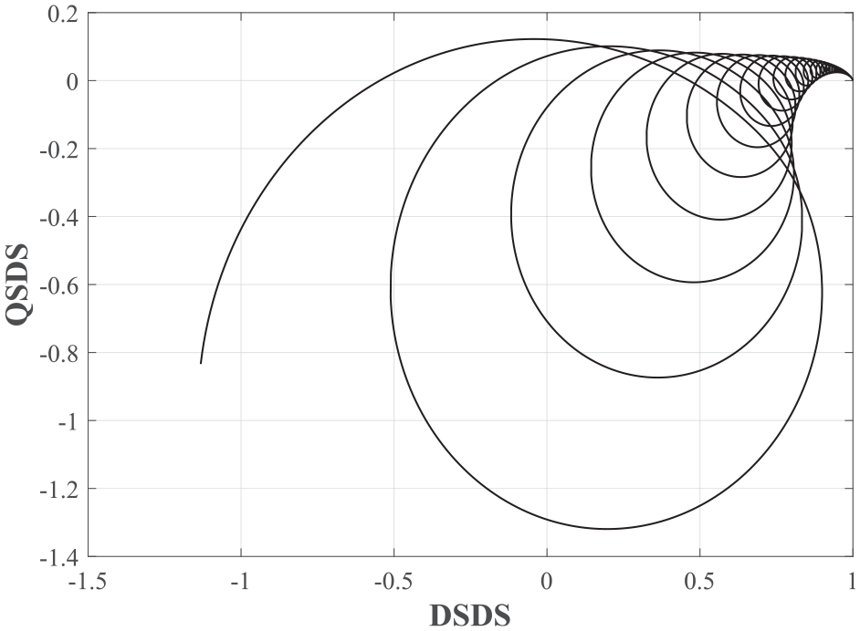
Plot of DSDS and QSDS at
Considering the varying designed parameters
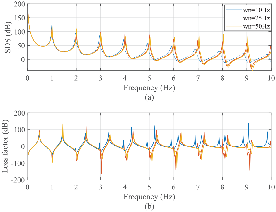
Magnitude plots of (a) SDS and (b) Loss factor under the
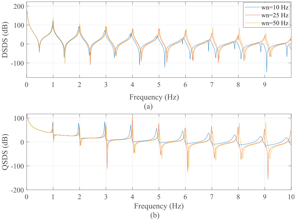
Magnitude plots of (a) DSDS and (b) QSDS under the
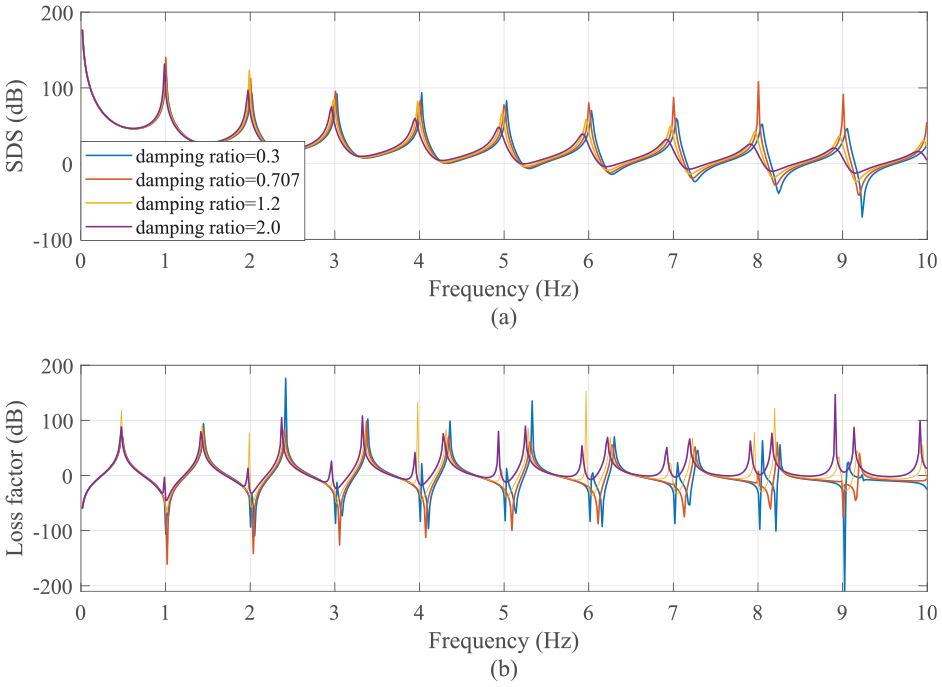
Magnitude plots of (a) SDS and (b) Loss factor under the
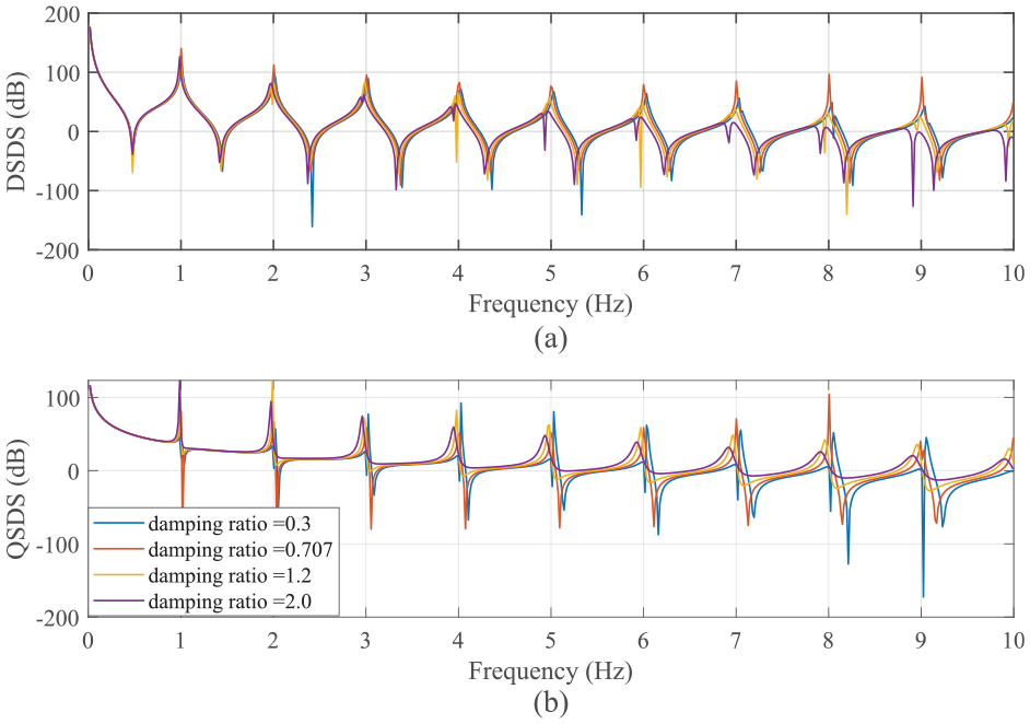
Magnitude plots of (a) DSDS and (b) QSDS under the
Considering the multi-periodic disturbance with periods
Under the multi-periodic disturbance, the reject error response can be given in Figure 19, where the result can be found that the tracking error is gradually decaying as shown in Figure 19. The larger errors can be found at 3, 5, and 6 s, which is generated by the non-continuous of the variable instantaneous frequencies period’s signal. The SDS, DSDS, and QSDS of the RLC system under the multi-periodic disturbance can be given in Figure 20 respectively. It can be found that the magnitudes of SDS and DSDS at harmonics of the disturbance is higher. Figure 21 shows the Loss factor and the magnitude of the Loss factor at harmonics (i.e.
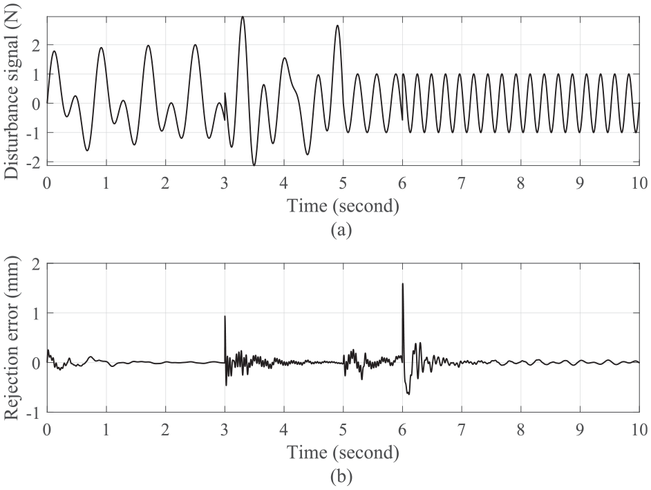
(a) Multi-periodic disturbance signal and (b) the reject error response.
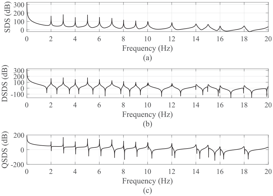
Magnitude plots of (a) SDS, (b) DSDS, and (c) QSDS with the multi-periodic disturbance.
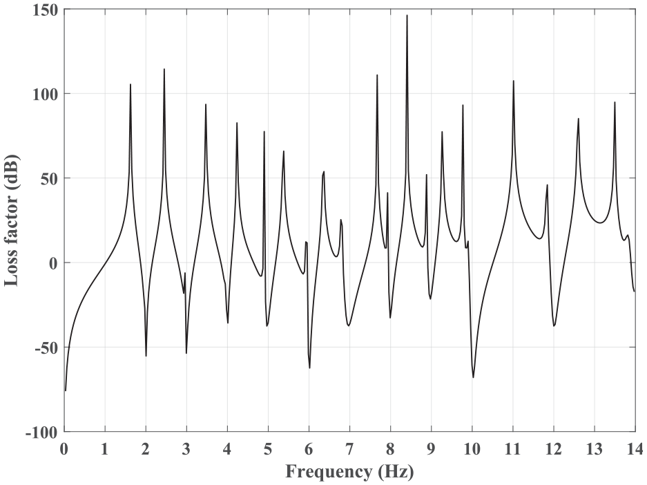
Magnitude plot of loss factor with the multi-periodic disturbance.
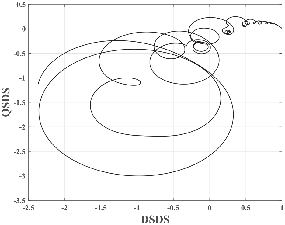
Coordinate plot of DSDS and QSDS with the multi-periodic disturbance.
From the simulation results, it can be found that the magnitudes of SDS, DSDS, QSDS, and Loss factor are better at harmonics of the disturbance. The RLC system can be achieved for a higher bandwidth with the designed low-pass filter
Conclusions
This paper presents a method for SDS characteristic identification of RLC system, where the SDS of the repetitive learning control system with multiple-periodic disturbances is given, and the DSDS and QSDS at harmonics of the disturbance are discussed based on the designed parameters of the RLC system. The influence of the controller’s parameters of the RLC system on SDS is studied by the frequency analysis method. From the simulation results, it can be found that the magnitudes of SDS, DSDS, QSDS, and Loss factor are better at harmonics of the disturbance. The results are given to illustrate that the parameters design of the proposed RLC can be obtained from the modeling of the SDS.
Footnotes
Declaration of conflicting interests
The author declared no potential conflicts of interest with respect to the research, authorship, and/or publication of this article.
Funding
The author received no financial support for the research, authorship, and/or publication of this article.
Data availability statement
The authors confirm that the data supporting the findings of this study are available within the article.