
Abstract
In this study, a biomechanical model mimicking the human hand-arm system under heavy disk excitation is developed to define the stability threshold between the preload vibration and the stress of the human hand-arm system. The fully electromechanical system, consisting of a DC motor, a transmission system, and three discrete masses representing the upper arm, forearm, and hand lifting a heavy disk, is connected by shock absorbers and various springs. The challenge of mimicking the angular activity of the elbow joint in torsion and flexion was also included to assess its contribution to system stability and to study the absorption of mechanical energy in the human hand-arm system. Finally, the movements of the model were described by a differential matrix equation, and its analysis facilitates the understanding of the threshold of the chaotic behaviors observed in an oscillating arms system. Specifically, it explores how the motion of a DC motor can be regulated using a single controller parameter within the context of a multi-degree-of-freedom human hand-arm system. The study uses numerical integrations to analyze system behaviors, with an emphasis on the use of frequency spectra, Poincaré maps, and bifurcation diagrams for visualization and interpretation. The results indicate that the system exhibits chaotic behavior when subjected to certain conditions, particularly when the mass load exceeds 35 kg. Imposing motion on the mass block further intensifies the chaos, leading to manifestations such as strong oscillations and frequency-synchronization effects. These characteristics, exhibited by the idealized model, which imitates the human body through a mechanical model and computation of the motions of the body, play a vital role in various fields of ergonomics and sports biomechanics. Understanding the dynamic behaviors of such systems, especially in response to varying conditions, has significant implications for engineering applications.
Introduction
The hand and arm constitute a very complex, continuous, and heterogeneous system comprising skin, muscles, and bones, adapted to various daily activities. To establish robust standards for tolerable vibration stress and exposure duration, it is imperative to improve an understanding of hand-arm system vibrations, particularly when interacting with external tools. This requires a comprehensive stability analysis and examination of the vibration responses of various elements of the hand-arm system. Robotic arms, designed to resemble human arms in structure and operation, are driven by a combination of mechanical and electrical components. They aim to facilitate smooth cooperation between humans and robots by mimicking their movements and functions. Research has focused on creating robotic arms that resemble human arms to accurately mimic human arm movements and gestures. The effectiveness of human-robot arms hinges on their ability to work harmoniously with humans, which underscores their importance and success in various applications. Dynamic modeling is used to elucidate the relationship between force and motion within a system. Such modeling is generally based on two fundamental principles, as explained in the publication. 1 The first principle, the Euler–Lagrange formulation, evaluates the system as a whole considering the overall kinetic and potential energy. On the contrary, the Newton-Euler formulation dissects the system into individual components. The choice of method depends on various factors such as the number and positioning of joints in the manipulator. For example, in Al-Qahtani et al., 2 the dynamic modeling of a robotic manipulator with four degrees-of-freedom (d.o.f) is detailed using the Euler-Lagrange formulation, with the base oriented horizontally. Additionally, Yuguang and Fan 3 used a combination of the Lagrange equation and the Morison formula to derive a dynamic model for a three d.o.f manipulator suitable for hydrostatic environments. In particular, the modeling process includes accounting for additional forces acting on the joints when the manipulator operates underwater. Human joints, which consist of various tissues such as cartilage, ligaments, and synovial fluid, interact to create internal loads transmitted to adjacent structures. Joints facilitate angular movement, contributing to the d.o.f problem, where humans can choose motor task solutions without compromising efficacy. 4 Despite their complexity, each human joint can be approximated by a mechanical model with similar functional capabilities. The selection of the appropriate joint model is crucial for valid and reliable results. Models of mechanical joints, both ideal and non-ideal, have been developed, with skeletal models typically using ideal joints (e.g. ball, universal, hinge). However, complex joints, such as the shoulder or elbow, require sophisticated modeling in the form of “closed-loop” systems, considering coupled rotations.5–7 Human-robot arms have applications in various industries, including manufacturing, assistive technology, and healthcare. Lovasz et al. 8 emphasize the importance of precise control and haptic feedback in human-robot arm applications, while Aljinovic et al. 9 illustrate how integrating human-robot arms into assembly lines can improve productivity and reduce worker fatigue. Challenges persist to ensure effective and safe physical interactions, with advances in artificial intelligence and machine learning contributing to the development of context-aware and adaptive control algorithms for human-robot arms. Effective control strategies are essential for precise and safe interactions between human-robot arms. Liao and Wang 10 have explored impedance control techniques, while Buerkle et al. 11 have explored the application of human intention recognition algorithms to anticipate and assist with arm movements. Nonlinear methods are increasingly being applied to accurately assess the stability and capture the intricate dynamics of these interactions. Stability analysis is crucial in human-robot arm-robot interactions, as it ensures that the system maintains balance and avoids unwanted behaviors. Non-linear analysis methods are used to evaluate the joint stability of the human-robot system in various interaction scenarios, providing a deeper understanding of the complex interactions between human operators and robotic arms. Real-time stability analysis is essential to ensure the safe operation of human-robot arms. Bascetta and Ferretti 12 employ Lyapunov-based analysis and predictive control algorithms to assess stability in real-time, significantly contributing to operational safety and security. One challenge of stability analysis is considering disturbances and uncertainties, and researchers like Faramin and Ataei 13 are investigating robust stability analysis methods that consider external disturbances and parameter uncertainties.
Future directions involve the integration of machine learning algorithms to improve stability predictions. The literature on the application of the bifurcation technique to the analysis of human-robot arm instability provides information on the complex behaviors and possible instabilities that can arise in these systems. Understanding the circumstances under which human-robot arms can display unstable behaviors depends on the study of instability. The bifurcation technique examines how the behavior of the system varies with dissimilarities in key parameters, providing a unique perspective. Gierlak and Warmiński 14 used bifurcation analysis to investigate how human operators and robot arms interact under various load scenarios. This method helps to find bifurcation points that suggest a possible instability. Madsen et al. 15 and other studies focus on creating dynamic models that take into account nonlinearity and coupling between human and robotic arms. Bifurcation techniques are then applied to these models to explore the parameter space and discover regions of instability. Park and Choi 16 examine how different human operator behaviors and control inputs affect joint system stability. Bifurcation diagrams that provide information about the transition from stable to unstable regions are revealed by bifurcation analysis. Krishan and Verma 17 use bifurcation techniques to assess possible instability and ensure safe operation to address security concerns. These analyses facilitate the design of control strategies that avoid system instability and improve operational security. Challenges in bifurcation-based instability analysis include dealing with high-dimensional parameter spaces and uncertainties. Tartaruga et al. 18 explore techniques to handle these challenges, including sensitivity analysis and uncertainty quantification. Ongoing directions involve combining bifurcation analysis with Poincaré for more comprehensive instability predictions and aim to refine Poincaré techniques, enhancing our ability to predict and mitigate instabilities in human-robot arm interactions.
In the fields of sports biomechanics and ergonomics, successful emulation of the human body has been achieved using mechanical models to compute body motions, joint movements, and muscle forces. Lee 19 introduced a biomechanical model of the human upper body incorporating bones and muscles. The model aims to model and control joint bones and muscles to simulate physics-based soft tissue deformations, while also incorporating detailed 3D anatomical geometries of hard and soft tissues. Multibody dynamics is a biomechanical technique widely used in sports, clinical settings, rehabilitation, and ergonomics to improve human performance,20,21 improve the prosthetic design, 22 and detect limb asymmetries after injuries, 20 and characterize the loads associated with repetitive movements. 23 It is reasonable to pursue simulation of the vibration response of the hand-arm system using similar methodologies. Therefore, the objective of this article is to construct a mathematical model designed to generate Poincaré and bifurcation signals associated with linear and nonlinear vibrational phenomena in human arm mechanisms. The paper makes a significant contribution by taking a comprehensive approach to the modeling and manipulation of dynamic biomechanical arm systems with elastic universal joints to model the elbow, with emphasis on their sensitivity to external stresses. The approach involves the use of a numerical tool to produce these signals, and particular emphasis will be placed on refining the initial parameters to ensure that their representation aligns with signals obtained experimentally in the literature. The subsequent phase of the study involves the use of these signals in purely numerical simulations of the mathematical model. These simulations aim to predict nonlinear vibrational phenomena, including contact or stability problems among coupled arm components.
The following sections of the paper are structured as follows: Section 2 describes the dynamic model of the electrical servomotor device responsible for rotating machine parts coupled to the two arms. Following this, Section 3 comprehensively describes the entire dynamic system and formulates the mathematical equations that govern the behavior of double arms with flexible joints. In Section 4, numerical simulation results are presented for a specific set of parameters to validate the efficacy of the proposed arms model. Finally, Section 5 provides a concise conclusion.
Description of the dynamic model
A descriptive biomechanical human hand-arm model is presented here, where masses represent the hand and the forearm, and the DC motor with the gear system represents the support, which mimics the shoulder of the body. An integrative approach is adopted for the development and validation of coupled arms under variable loads. The article elucidates the dynamics of human arms featuring five d.o.f, with the dynamic model of the manipulator’s arm derived through the application of Lagrangian formalism. This section details model selection and summarizes its essential features.
Biomechanical model description
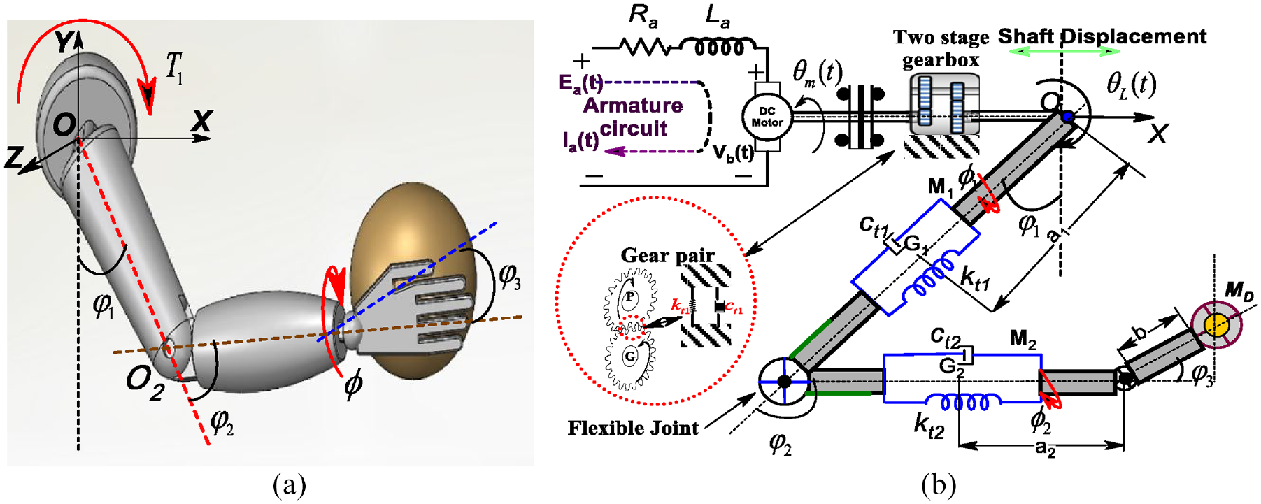
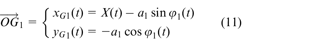
The human hand-arm system presented in Figure 1(a) is recognized as one of the fundamental kinematic structures, consisting of a planar arm with two rotating joints that move within the X-Y plane. The schematic diagram shown in Figure 1(b) illustrates the kinematic structure of the arm system, presenting its fundamental elements, their spatial arrangement within the overall system, and its key parameters. More precisely, the diagram delimits two rigid arms characterized by lengths denoted L1 and L2, each having a mass represented, respectively, by M1 and M2. Additionally, the distance between the joint rotation axis and the center of gravity of each arm is designated by a1 and a2. The moments of inertia of the arm bodies (J1 and J2) are with respect to an axis that passes through the center of gravity and parallel to the horizontal axis X. The deviation of the arm from its initial position (where the joint angle is not equal to 0°) is described by the angles
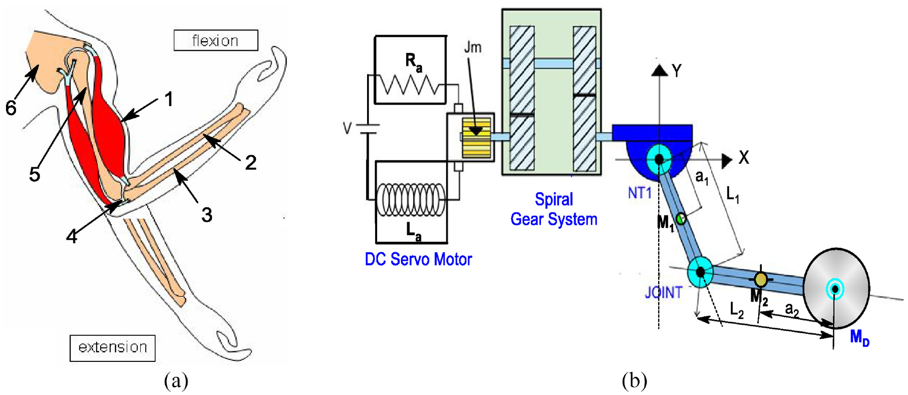
(a) Schematic drawing of the hand-arm system, 1. Contracted bicep, 2. Ulna, 3. Radius, 4. Elbow joint, 5. Humerus, 6. Shoulder and (b) corresponding simplified mechanical model.
The elbow (coupling joint) is a hinge joint that allows forearm rotation. The movement produced by the joint describes the compression and extension of the rotating arms,
Electromechanical control system components (DC motor)
The proposed model involves a DC motor connected to a gearbox system that provides torque and speed to move the elbow arm. In this study, the DC motor operates by electromagnetic induction to produce rotational motion. In the closed-loop control system, the motor’s output (such as speed or position) is continuously monitored to provide feedback on motor performance, allowing adjustments to the input voltage or current. Closed-loop control systems offer greater accuracy, reliability, and stability, especially in dynamic or variable operating conditions. Understanding and optimizing control parameters is crucial to achieving desired performance characteristics in a biomechanical arm system. The DC motor and gear system support imitate the shoulder attached to the body. The shoulder (motor) is considered to generate a rotational movement that can be associated with Euler angle notation
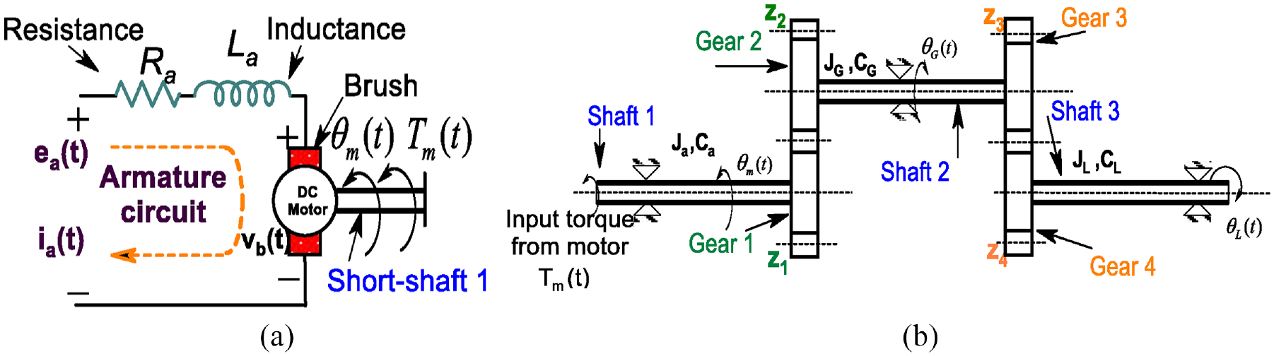
Schematic diagram of a DC machine: (a) motor schematic and (b) transmission gear system.
The armature speed of a DC motor is regulated by the armature voltage e
a
= Ktev, with Kirchhoff’s voltage law allowing the calculation of the total torque. The relationship between armature current

The expression for the motor torque (T m ) is formulated in Laplace form, taking into account the proportional relationship with the armature current (I a ) and the impact of inductance (L a ), as outlined by Ogata 24 .

This analysis focuses on the use of gears in robotics applications to reduce the load’s angular speed by a factor of n, analyzing output parameters such as internal damping Cmeq and gear inertia Jmeq, respectively. For this gear-train system displayed in Figure 2(b), the equation for torque equilibrium with respect to

The desired transfer function can be obtained by simplifying equations (1) and (2) and removing
Where
In this work, the utility of the transfer function concept emerged from the identification of fluctuations associated with oscillations in the power system that could potentially be attenuated by a flexible mechanical transmission system. Force characteristics in system analysis are crucial to understanding inherent properties such as inertia, damping, and stiffness. Accurate predictive models help reproduce system dynamics, such as the driving force of an arm, as demonstrated by Bernstein 25 and expressed by:
Here, N g and r mg are, respectively, the ratio of the planetary gearbox and the radius of the motor pinion.
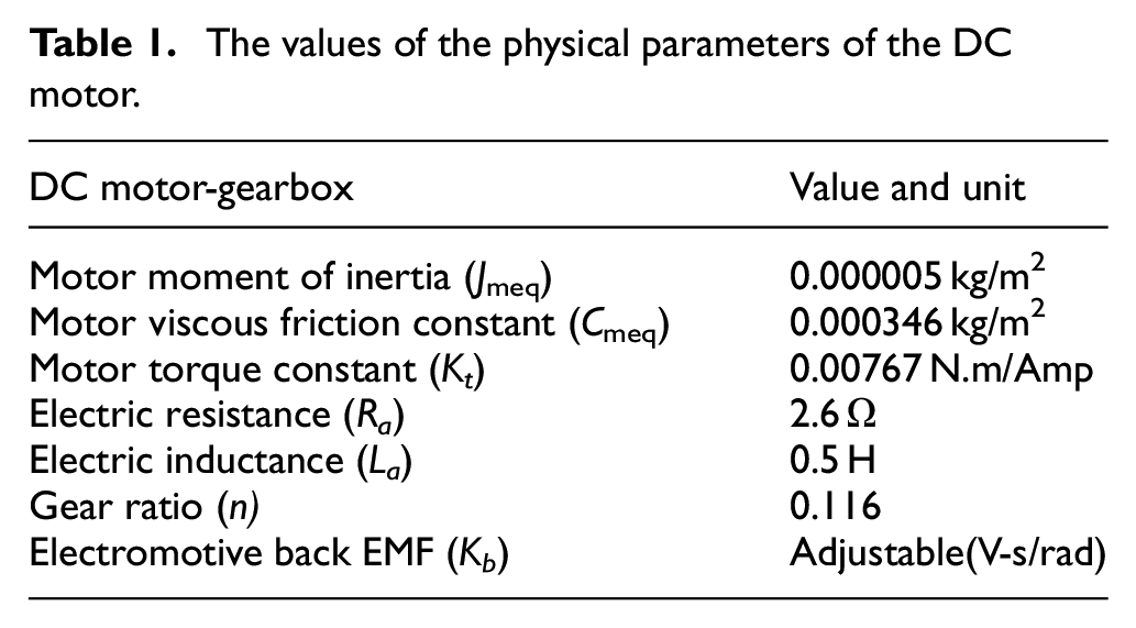
In this study, a representative set of values of the DC motor parameters is chosen from Table 1.
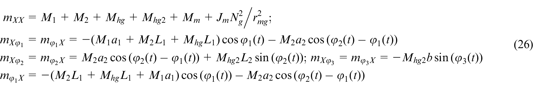
The values of the physical parameters of the DC motor.
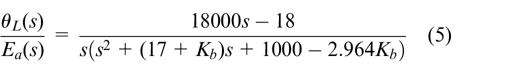
Implement a feedback mechanism defined in equation (5), it is possible to continuously monitor the state of the system and adjust the control input accordingly by varying K b . A first simulation allows us to obtain the unit step response of the transfer function given by equation (5), in the unstable cycle, which further represents the angular displacement of the output shaft and is presented in Figure 3. A family of transfer function curves with different values of adjustable K b is shown in Figure 3(a). The Nyquist diagram associated with K b shows the convergence of the response graphs of Figure 3(a) and Nyquist Figure 3(b) toward the point of instability. The presence of closed-loop poles in the left half-plane, as shown in Figure 3(b), confirms the stability of the system. This indicates that Kb = 1.92 is the critical value for the appearance of limit cycles. Similarly, on the Nyquist diagram associated with Kb = 80.98, the graph of K b passes through the point (0, 0), signifying the imminent disappearance of the associated limit cycle. Figure 3 illustrates how the speed of the DC motor can be controlled using adjusted controllers (K b ). The K b controller offers better performance in both transient and steady-state responses. From the results of the motor speed simulation displayed in Figure 3(c) and (d), the parameter K b value may result in greater sensitivity to load changes and less stable speed control. The simulation in Figure 3(c) diverges from the original equilibrium point, in agreement with the predictions of the initial investigation. Adjusting the back EMF. The constant K b can enhance stability, as shown in the unit-step response in Figure 3(a) and Nyquist plots in Figure 3(b), where a symmetric and stable ellipsis indicates linear and stable behavior.
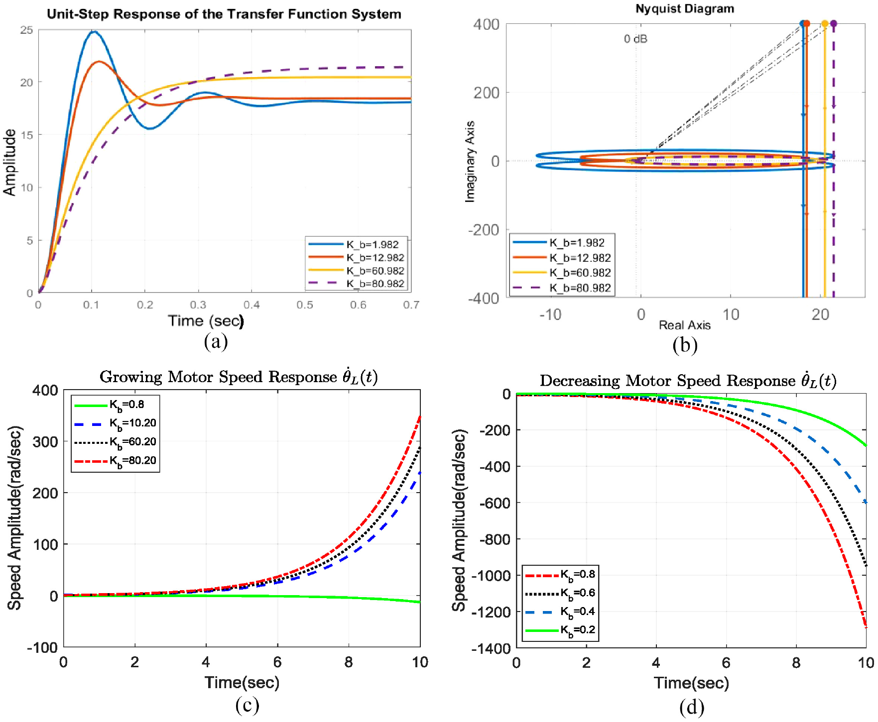
The transfer function. It is seen that the third set of parameters K b controls the system with greater precision: (a) time (s), (b) real axis, (c) time (s), and (d) time (s).
Establishment of the joint disturbance function
For the system considered, although they have limitations compared to more specialized components, the shock absorbers and springs are integrated into biomechanical models to simulate specific aspects of human muscle-tendon-ligament structures. To validate the model, the behavior of the joint is compared to that of a cardan shaft. By performing the inverse Laplace transform, the time-domain representation of the DC motor response, allowing the analysis and interpretation of its behavior over time, can be obtained as
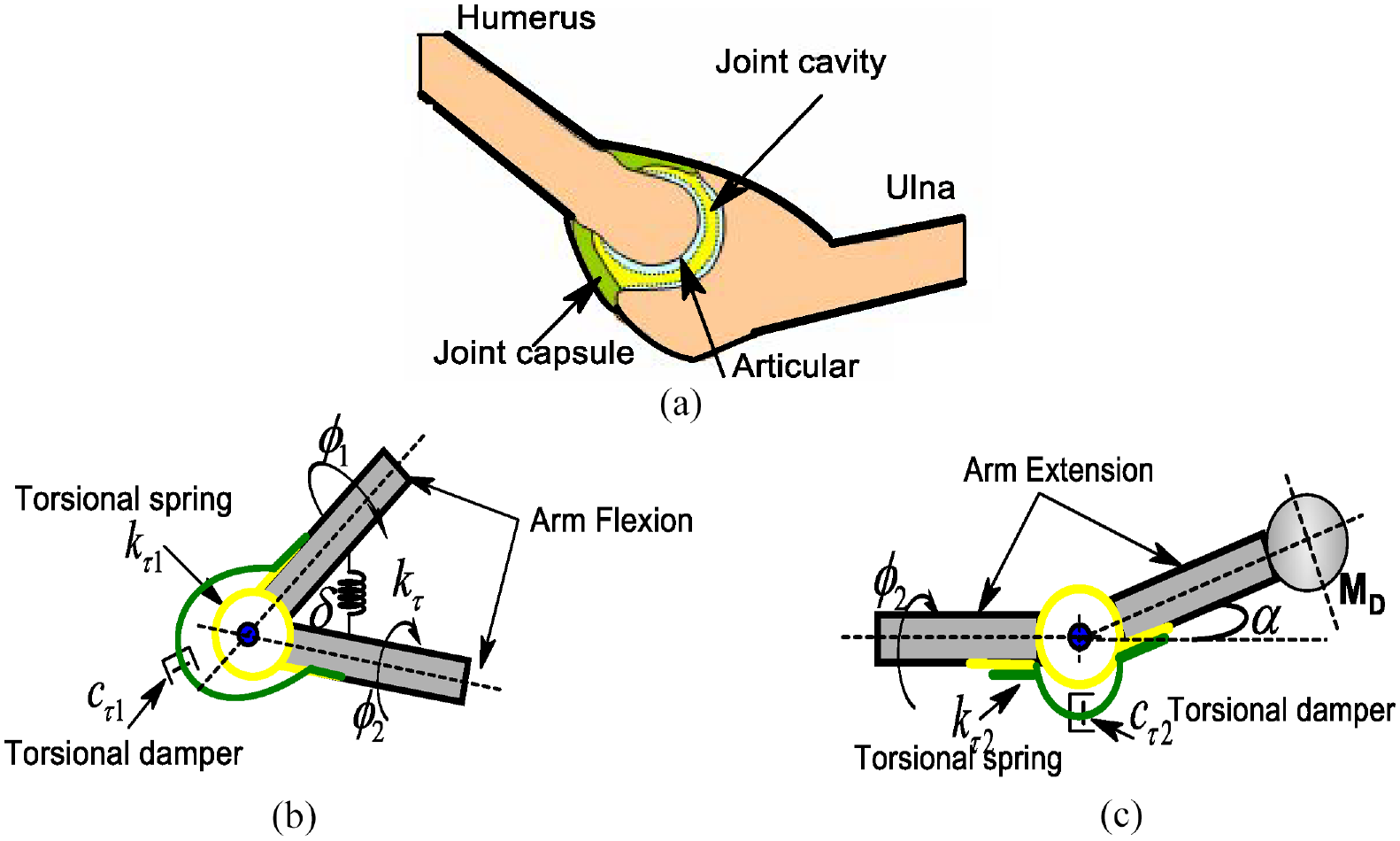
Simplified modeling of the elbow joint in flexion and extension: (a) arm and bone anatomy, (b) arm in flexion, and (c) arm in extension.
The model incorporates both a torsion spring and a damper, which effectively reproduce the arm flexion in Figure 4(a) and the extension in Figure 4(b). Flexion decreases the angle, while extension increases it, as shown in Figure 4(a) and (b). To simulate different postures of the arm, it is assumed that the joint angle

This study uses

The equation can be solved by referencing equation (8) and applying the tangent trigonometric function after appropriate manipulation.
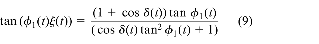
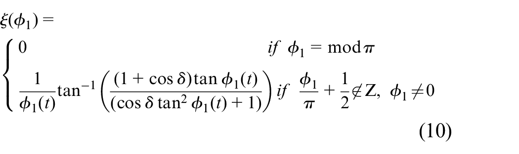
The model of a flexible joint arm manipulator, given in equation (10), defines the perturbation function for a significant variation angle. This is determined by rearranging equation (9) and solving for
The characteristic dynamic behaviors of the disturbance function
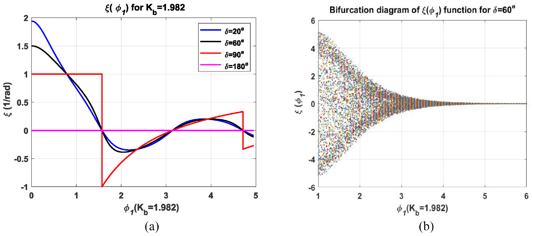
(a) Arm joint disturbance for four values of
The angles were established for individual oscillations in the interval [20°; 180°]. Figure 5(a) illustrates the deformations measured according to different angles of rotation of the joint and the bifurcation obtained numerically. The joint oscillates, causing periodic changes and misalignment angle variations. High values of the parameters increase the instability of arm movement, with angles above 60° showing significant instability. The observation aligns with Figure 5(b), which shows a map of the bifurcation diagram of the perturbation function. Applying the first iterative method with a step length of 0.01, equation (9) shows that around
Chaotic behaviour of the joint disturbance function
To examine the impact of disturbance parameters on system motion, a bifurcation diagram can be generated using MATLAB. Figure 6 shows that the joint disturbance function given by equation (10) where
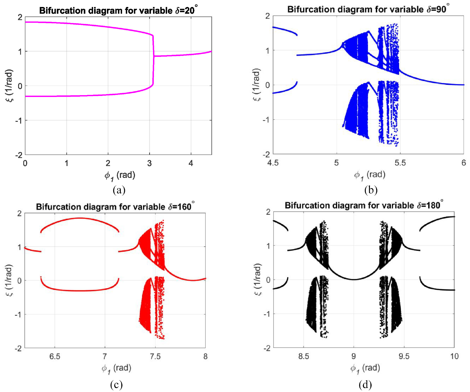
A series of hinge bifurcation diagrams when: (a)
Figure 6 represents a series of graphs showing the bifurcation behavior of the arm joint system at different angles of misalignment. Bifurcation diagrams are used to visualize changes in the dynamics of a system when a parameter, such as a misaligned angle, varies. From Figure 6, it is evident that various bifurcation types occur before the onset of chaos. A pitchfork bifurcation is observed in Figure 6(a)
Limitations of the perturbation model
Based on the series of bifurcation diagrams, when
In the subsequent section, particular attention is directed toward the integration of the electromechanical control system with the hand-arm system under the influence of the controller parameter. Consequently, the combination of the motor, gear, and hand-arm components, illustrated in Figure 7, will generate the system’s response to the impulsive disk disturbance.
(a) Schematic description of the mechanical arm system and (b) conceptual design of the mass spring damper.
Mathematical modeling of the system
System description and assumptions
The biomechanical model consists of three discrete masses, dampers, and springs (Figure 7). The model assumes that the mass of each rod is concentrated at its center of gravity and that rotational inertia is neglected. It also assumes that the upper and lower rods have significant angular misalignment due to the coupling of a single U-joint to maintain the twisting motion of the rods and preserve nonlinear coupling effects, as shown in Figure 7(a).
Following the works of Tchomeni and Alugongo,
28
the assumption is made that the elbow’s d.o.f joint angle
The center of gravity of the mass of link-1 to 3 can be expressed as:
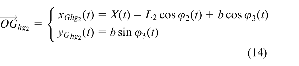
The linear velocity of each component can be determined by taking derivatives of equations (11)–(14) over time. However, deriving the governing equation for a coupled double-arm system is challenging due to intricate derivative calculations. The Lagrangian energy approach, which analyzes the kinetic, potential, and Rayleigh dissipation energies, offers a more efficient method to formulate the system equations.
Energy principle expression
The sum of the kinetic energies of translation and rotation of the geared motor is given by the following.
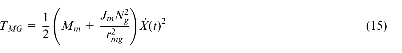
The combined rotational inertia of the gears at the input link is grouped and represented by J m , and rmg is the load on the output link simulated through viscous torsional resistance. For real-time implementation, it is assumed that the length L2 of the output shaft is slightly longer than that of the input shaft L1, both being treated as rigid shafts. The total kinetic energy due to motion is the sum of the translational and rotational energies of each component, and it is expressed as:
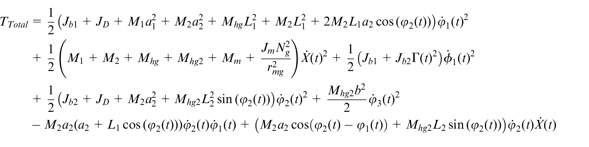
where J b 1, J b 2, and J D are, respectively, the moment of inertia of the first and second arm rods and the moment of inertia of the concentrated mass at their pivot point O.

The hinge between shaft 1 and shaft 2 is modeled as a twisting motion, where
The corresponding Rayleigh dissipation function used for this system is given as:

Thus, the torsional damping coefficients of the hinge of the bonding coupler are
Similarly, the derivatives of equations (16)–(19) with respect to
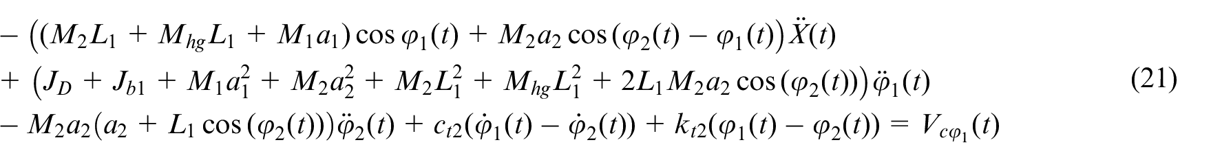

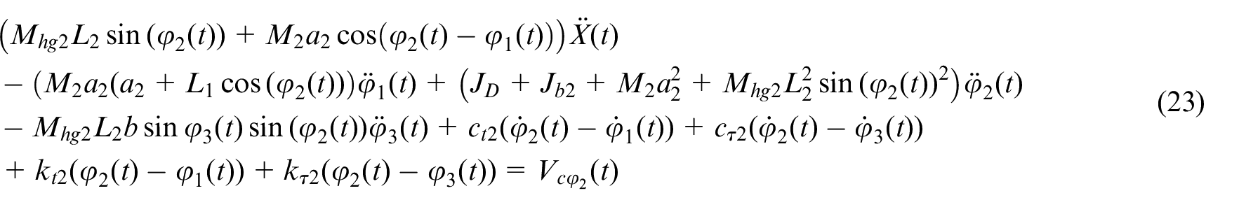

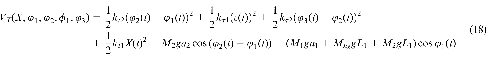
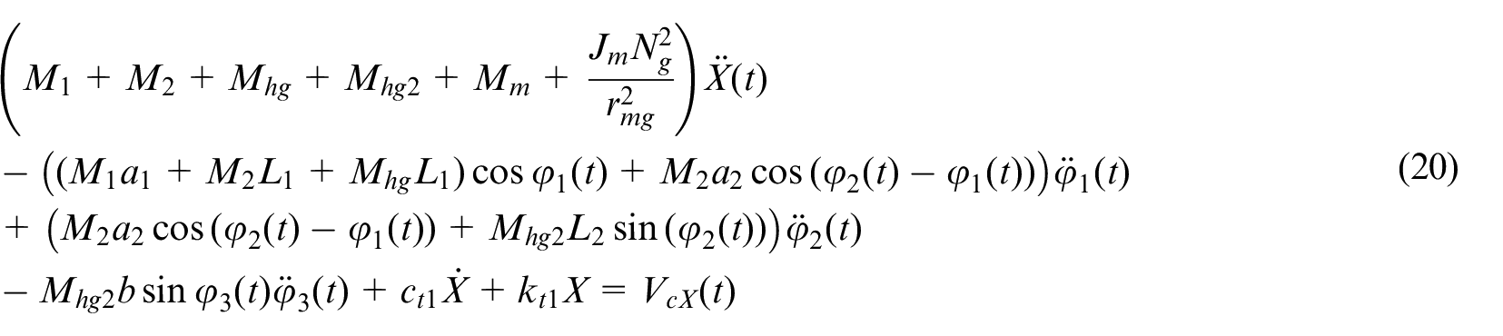
Thus, the combined equations (20)–(24) are the equations of motion of a coupled arm system, established using the principles of engineering dynamics, relevant and suitable for the analysis of the behavior and performance of the system in practical engineering applications. However, it can be noted that equation (24) demonstrates that vibration in the
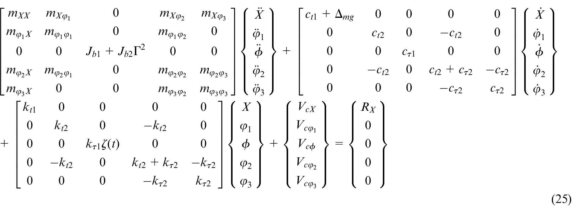

R X and Vcn represent the generalized vector forces and some of the nonlinear terms derived from the coupling generalized coordinates. The specific expressions for each of these generalized vector terms are provided in Appendix A.
Numerical results of dynamical non-linear systems
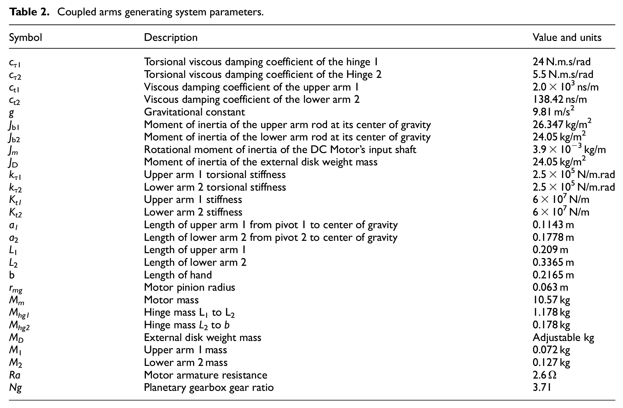
As an initial objective of the overall analysis of the device, it is necessary to solve the equation that governs the oscillation of the system. Equation (25) is used to study system stability control and harmonic solutions using fast Fourier transform, orbit, and arm displacement, thus providing real-time feedback on weight variation. The study involves numerical solutions for a nonlinear model representing a coupled arm system, uncovering chaotic fluctuations under specific conditions using Poincaré maps and bifurcation diagrams. A representative set of parameter values described in Table 2 is chosen to perform simulations through the time domain expressions of equation (25).
Coupled arms generating system parameters.
Numerical results and discussion
Due to the strongly nonlinear characteristics of the joint impact arm system, extracting precise vibration responses directly poses a challenge. Obtaining exact solutions proves to be difficult, leading to the transformation of the derived equation (25) of motion into a set of first-order differential equations. Subsequently, the fourth-order Runge-Kutta method is applied to solve these equations and acquire data. In the course of the calculation, a smaller integration step is selected to guarantee the stability of the solution and prevent numerical divergence, particularly at points where the derivatives of the impact forces of the load are present.
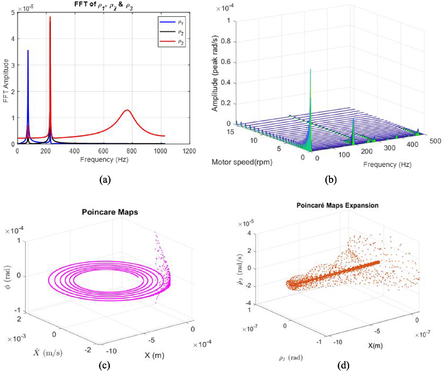
Amplitude frequency response for each link arm at a critical point (MD = 0, Kb = 1.982,
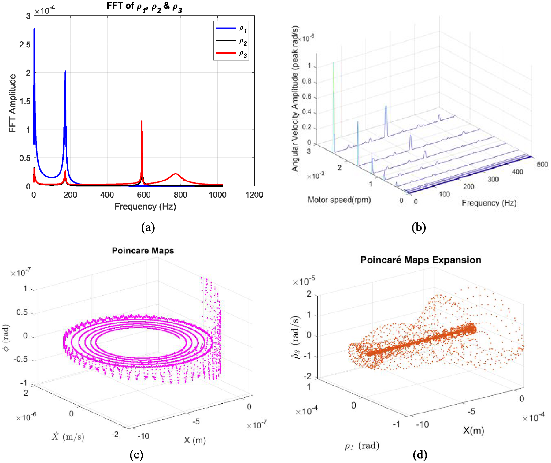
Amplitude frequency response for each link arm at a critical point (MD = 15, Kb = 1.982,
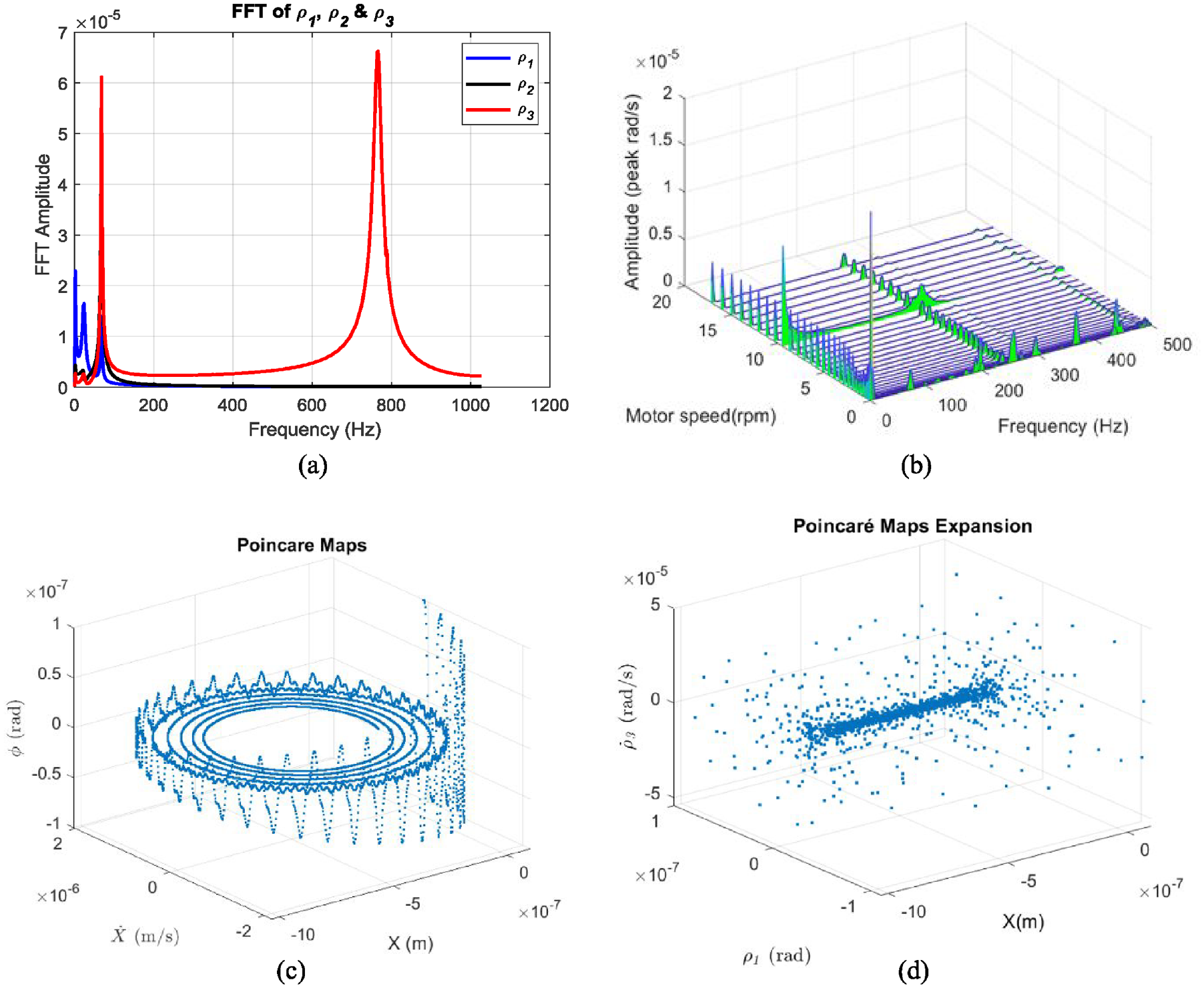
Amplitude frequency response for each link arm at the critical threshold (MD = 35 kg, Kb = 1.982,
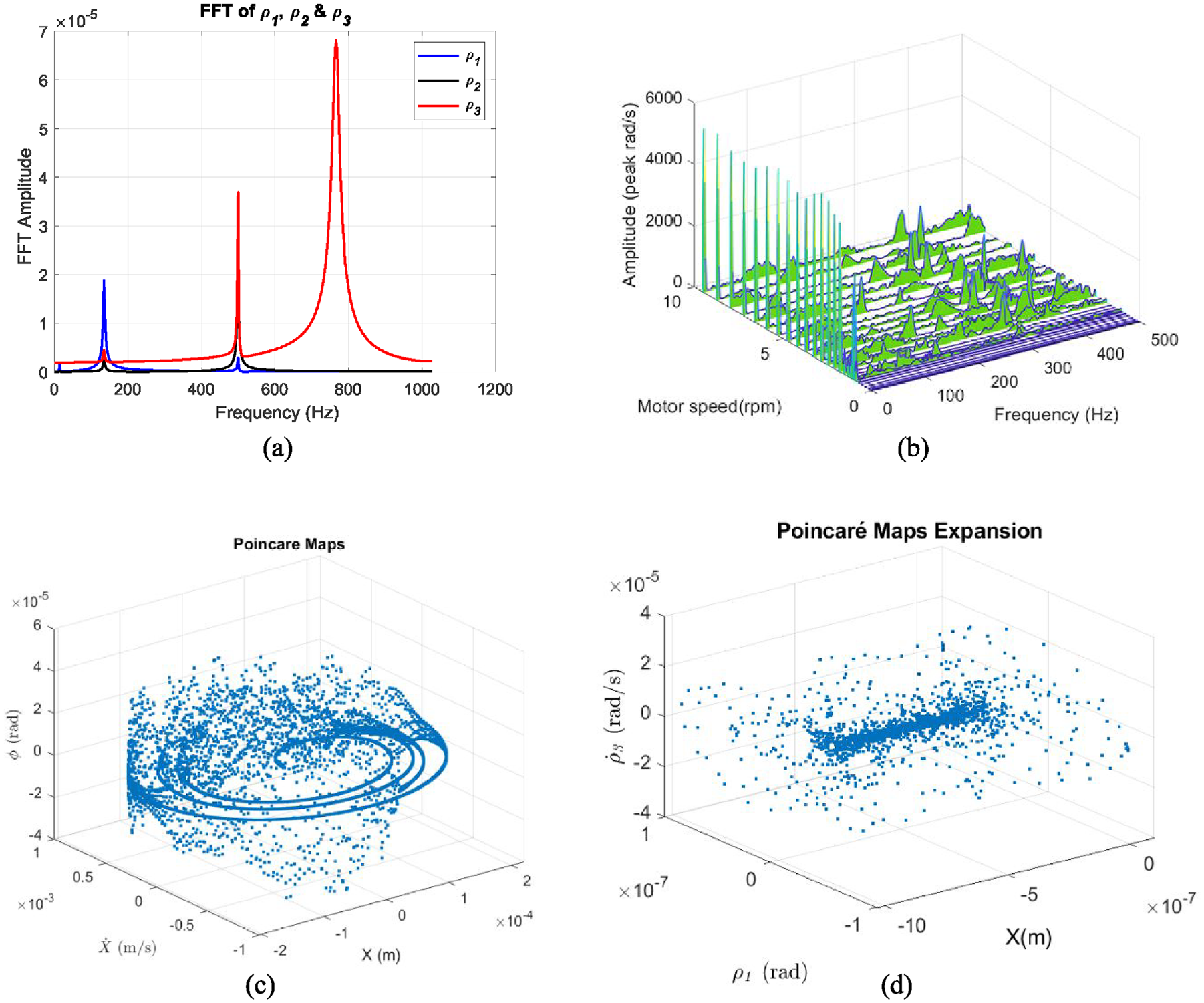
Amplitude frequency response for each arm above the critical threshold (MD = 50 kg, Kb = 1.982,
Aperiodic (chaotic) behavior in a dynamical system is characterized by a broadband frequency spectrum. In addition, the frequency spectrum is densely populated, with multiple peaks observed around the fundamental frequency. The electromechanical system exhibits significant resonance peaks near the first critical speed. Observations of the frequency spectrum in Figures 8(a), 9(a), 10(a), and 11(a) reveal peaks at frequencies 42.123, 130.381, and 764.232 Hz corresponding to spindle speed rotation. Figures illustrate that arm 3 is significantly more affected by the preload action compared to input arm 1 and intermediate arm 2. Figure 8(a) shows that the third arm of the system displays super-harmonic resonances (also referred to as subcritical resonances) equivalent to the combination of the input link 1 and intermediate link 2’s first-order critical speed. Under a charging load of 50 kg, high amplitudes were observed at the same resonant frequency points. However, monitoring the evolution of the frequencies for each arm does not indicate a malfunction in the system, and there is no evidence of fault frequencies for the analyzed arms. It implies that a system with three fundamental frequencies is referred to as a third-order periodic system.
The spectrum presented in Figure 8(a) lacks a rich variable content frequency. The observed divergence in frequency amplitudes indicates the presence of the jump phenomenon called “resonance.” To illustrate nonlinear resonance, temporal simulations were impractical due to system sensitivity. The 3D waterfall power spectrum technique is used to identify various types of chaotic behavior in systems. For nonlinear systems, a multiple of fundamental frequencies indicates superharmonics, while incommensurable ratios suggest quasiperiodic behavior. The aperiodic behavior is characterized by broadband frequency spectra and dense frequency spectra, with more peaks around the fundamental frequency. Instead, a 3D waterfall transform analysis revealed systematic variations in frequency over time. Figures 8(b), 9(b), 10(b), and 11(b) display the 3D waterfall wavelet synchrosqueezing distribution of the signals from the three arms at different speeds. In contrast to the previous FFT spectrum, it is now much easier to identify the type of chaotic motion visible in the signal. The frequency-based disturbance analysis can be distinguished among other frequencies in this case. The 3D waterfall representation allows for clear identification of time and frequency for each frequency, making it easy to interpret and confirm frequency complexity (number of harmonics and increases in amplitude at rotation frequencies), indicating system instability. When a very light mass is introduced, a relatively rapid increase in the period is observed. For MD = 15 kg, the motion, although nonchaotic, tends to become increasingly unpredictable. This trend toward chaos is confirmed with a Poincaré section where the initial conditions are slightly different to observe the presence or absence of a major characteristic of chaos. Sensitivity to the threshold load is obtained by modifying the value of the mass to be transported by arm 3 (MD = 35 and 50 kg).
Poincaré maps are used to simplify complex systems and provide insight into their nonlinear dynamic behavior. A closed curve on the map indicates quasiperiodic behavior, making it possible to visually distinguish nonchaotic movements. The initiation of chaos on the Poincaré map is marked by a distinct set of points. For MD = 35 kg, a distinctive phenomenon of recurrence of nonsimple periodicity is observed. The Poincaré section for this value exhibits an ellipsoidal curve, as indicated by the first Figures 8(c), 9(c), 10(c), and 11(c). The subsequent image, depicting the Poincaré section for MD = 35 kg, illustrates a less predictable behavior. However, the overlay of the two solutions with different threshold loads eliminates the possibility of chaos. Once again, the sensitivity of the movement is influenced by various values of the MD parameter that can be examined. In this context, different behaviors are observed more broadly. It is evident that around MD = 35 kg, the movement becomes more responsive to the threshold load, progressively becoming more unstable until MD = 50 kg, eventually transitioning into chaos. The region near MD = 50 kg signifies a shift toward chaos, as solutions with close initial conditions diverge, leading to a noticeable disparity between scattered points (Figures 8(d), 9(d), 10(d), and 11(d). It is observed that a high value of M D significantly influences the movement, leading it toward greater chaos. This intuition is supported by a Poincaré and bifurcation section, specifically for MD = 50 kg while maintaining the angle and K b constant. The observation here indicates that, for a substantial MD, in contrast to the previous scenario, the movement becomes highly chaotic, with the chaos manifesting definitively and prominently.
Bifurcations of nonlinear arm systems for different mass values
To conclude, four bifurcation diagrams will be generated, each corresponding to different values of the external weight load, M D . According to the specific magnitudes of the M D external weight load, the bifurcation analysis of the nonlinear system is performed and presented in Figure 12.
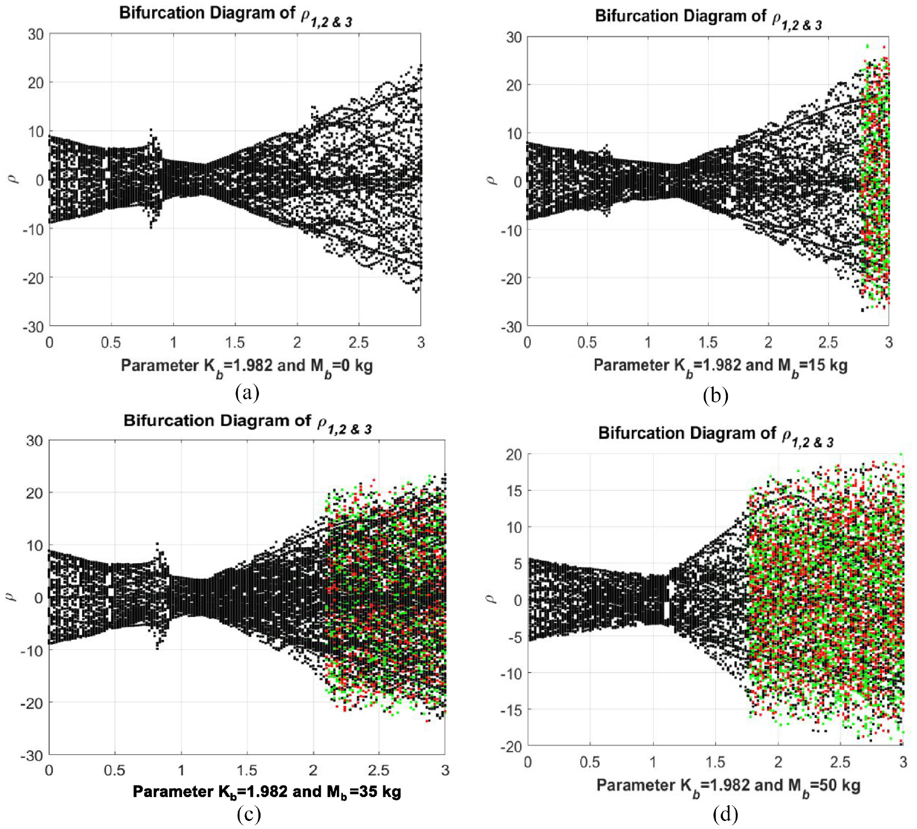
Bifurcation diagram of equation (25) when Kb = 1.982,
During this examination, the parameter K b is kept constant at a value of Kb = 1.982, while and = 60°. The values chosen for M D in this section are MD = 0, 15, 35, and 50 kg, allowing a thorough analysis of the behavior of the system in a range of external weight loads. The chaotic behavior of the system is also validated by the bifurcation diagram, shown in Figure 12, where the chaotic behavior is based on multiple irregularities, seemingly random frequencies, and a lack of clear patterns that can correspond to different modes or components of the coupled arms. In system (25), the amplitude of the control input, M D , is regarded as a bifurcation parameter, while the others are kept fixed, and it is calculated to illustrate the various dynamical behaviors of equation (25). The bifurcation diagram for parameter M D reveals both chaotic and periodic behavior of the system across a broad range of M D values, exhibiting a stable limit cycle followed by transient chaos. Using these four bifurcation diagrams, it is observed that the impact of forced motion on the chaotic nature of movement depends on its relative intensity with respect to M D and the inherent stability of motion without external influence. Specifically, it is observed that for 0 < M D < 50 kg, the system exhibits a highly periodic motion in the absence of forced movement, and chaos requires M D to exceed 35 kg. This is comprehensible, given our earlier conclusion that, for forced movement, MD > 35 kg induces system unbalance, establishing 35 kg as the threshold value for chaos.
Dynamic analysis based on arms response
Considering the topic of this article, one of the objectives is to provide a qualitative interpretation of the results and an analysis of the behavior of interconnected arms from the perspective of bifurcation theory. In dedicated terminology, the problem has external load M D as a control parameter and gain Kb = 1.982 as a fixed parameter corresponding to a bifurcation of nodes of periodic orbits. It remains to confirm this assertion through two-time simulations initialized with values much larger than the amplitude of the stable periodic orbit so that they converge toward it if it exists. In this section, the nonlinear dynamics of arms connected via a flexible joint are analyzed, revealing complex motion patterns, oscillation behaviors, and stability characteristics under various loads and system configurations. A control gain Kb = 1.982 is selected and the simulation is initialized with a minimal lifting mass MD = 0 kg and a maximum mass. MD < 50 kg.
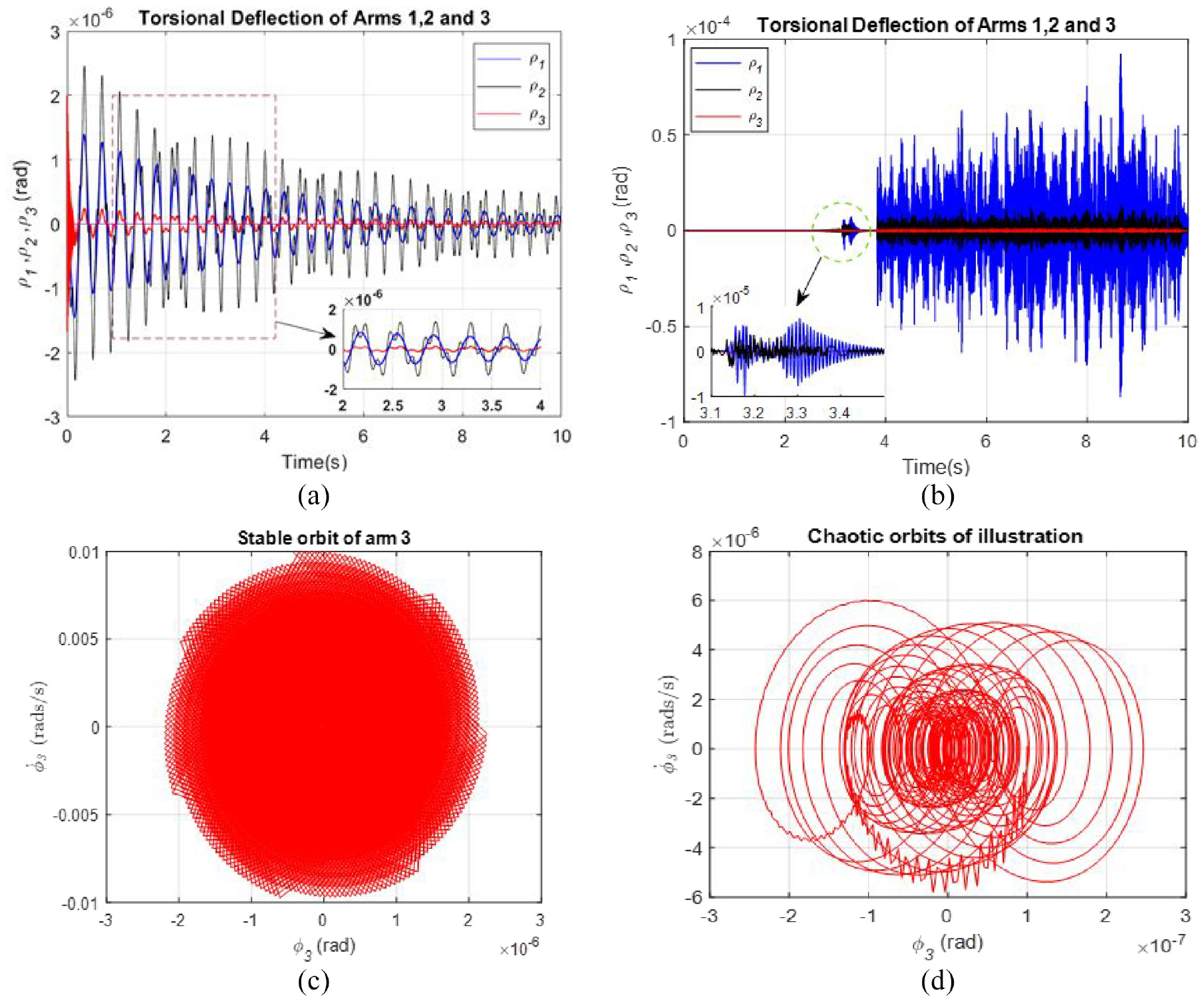
Time simulation of connected arms lifting a specific load (MD = 0 and 50 kg and Kb = 1.982).
Conclusions
This article explores the steady-state operation of a DC motor connected to a flexible joint manipulator with a double arm, focusing on chaotic behaviors. The dynamic equations are formulated using the energy principle, and the model incorporates non-linearities during arm flexion and extension for enhanced accuracy. The motor introduces a d.o.f to simulate the clavicle’s role in arm movement, fostering interaction between two manipulators. The study demonstrates that due to its highly non-linear dynamic characteristics, a two-arm system designed for weightlifting exhibits complex phenomena, including higher subharmonic oscillations, bifurcations, and chaotic movements. The arms exhibit structural and kinematic complexities, such as offset attachments and variable link cross-sections. The system shows increased instability when external disturbances occur due to weight lifting. The chaotic nature of the system is confirmed using the Poincaré map and bifurcation diagram, highlighting the coexistence of chaotic orbits in all instances and providing a quantitative characterization of the system responses. The Poincaré section plays a crucial role in observing bifurcations and chaos of nonlinear oscillators. In the case of a heavy system, the response includes multiple high-order harmonic motions and chaos with significant contamination, which poses problems for easy distinction in both orbit plots and frequency spectra, and strengthens the conclusions drawn from the numerical simulations.
In future research, the authors aim to expand upon current research in the following areas:
Conduct experimental studies to validate the proposed biomechanical arm model under real-world conditions.
Employ advanced analytical techniques such as Lyapunov algorithms to enhance stability analysis and refine adaptive control methods, allowing the biomechanical arm system to adapt to varying loads more effectively.
Create a more faithful mechanical imitation of human musculoskeletal structures, advanced materials, and actuators with properties closer to those of biological tissues.
Footnotes
Appendix
Credit authorship contribution statement
Declaration of conflicting interests
The author(s) declared no potential conflicts of interest with respect to the research, authorship, and/or publication of this article.
Funding
The author(s) disclosed receipt of the following financial support for the research, authorship, and/or publication of this article: This work is based on research supported in part by the Vaal University of Technology (VUT), South Africa, through the Department of Higher Education and Training University Capacity Development Grant.
Data availability statement
Data sharing not applicable to this article as no datasets were generated or analyzed during the current study